

Page 1

HP NETSERVER AA SOLUTION
Endurance Release Notes
Release 4.0 Service Pack 1
Printed in August 2001
Page 2

NOTICE
The information contained in this document is subject to change without notice.
Hewlett-Packard makes no warranty of any kind with regard to this material, including, but not limited to,
the implied warranties of merchantability and fitness for a particular purpose.
Hewlett-Packard shall not be liable for errors contained herein or for incidental or consequential damages
in connection with the furnishing, performance, or use of this material.
Hewlett-Packard assumes no responsibility for the use or reliability of its software on equipment that is
not furnished by Hewlett-Packard.
This document contains proprietary information that is protected by copyright. All rights are reserved. No
part of this document may be photocopied, reproduced, or translated to another language without the prior
written consent of Hewlett-Packard Company.
TRADEMARK NOTICE
Assured Availability, ComputeThru, Computing for the long run, Constant Computing, Endurance, Marathon
Assured, MIAL, SplitSite, and the Marathon logo are either registered trademarks or trademarks of Marathon
Technologies Corporation in the United States and/or other countries.
Microsoft, MS-DOS, Windows, Windows NT, and Windows 2000 are either registered trademarks or trademarks of Microsoft Corporation in the United States and/or other countries.
All other brands and product names are trademarks of their respective companies or organizations.
SOFTWARE REVISION
The revision of the Endurance software that this document supports is Revision 4.0.1-SP.EA.
Hewlett-Packard Company
Network Server Division
Technical Communications MS 45SLE
10955 Tantau Avenue
Cupertino, California 95014 USA
ã Copyright 2001, Hewlett-Packard Company
ii Endurance Release Notes for Release 4.0 Service Pack 1
Page 3

Table o f C o ntents
About This Product . . . . . . . . . . . . . . . . . . . . . . . . . . . . . . . . . . . . . . . . . . . . . 1
HP Netserver AA Solution Documentation . . . . . . . . . . . . . . . . . . . . . . 1
Additional Documentation on the Customer Support Web Site . . . . . . . . . . . 2
Platform Support and System Requirements . . . . . . . . . . . . . . . . . . . . . . . . . 2
CE Dual Processor Support and CPU Requirement . . . . . . . . . . . . . . . . . 2
CE Configuration Requirements . . . . . . . . . . . . . . . . . . . . . . . . . . . 3
CE Motherboard BIOS Settings. . . . . . . . . . . . . . . . . . . . . . . . . . . . 4
Platform Support . . . . . . . . . . . . . . . . . . . . . . . . . . . . . . . . . . . 4
Motherboard Requirement . . . . . . . . . . . . . . . . . . . . . . . . . . . . . . 5
Memory Requirement . . . . . . . . . . . . . . . . . . . . . . . . . . . . . . . . . 5
Marathon Interface Card (MIC) Requirement . . . . . . . . . . . . . . . . . . . . 5
Partition Format Requirement . . . . . . . . . . . . . . . . . . . . . . . . . . . . . 5
Operating System Requirements . . . . . . . . . . . . . . . . . . . . . . . . . . . . . . . . . . . 5
Endurance Enhancements in Release 4.0 Service Pack 1 . . . . . . . . . . . . . . . 6
Support for Windows 2000 Service Pack 2 . . . . . . . . . . . . . . . . . . . . . . 6
Support for Long Distance SplitSite® Distances Up to 10 Kilometers. . . . . . . . 7
Marathon Interface Card (MIC) 4.3 Available . . . . . . . . . . . . . . . . . . 7
Singlemode Fiber Support . . . . . . . . . . . . . . . . . . . . . . . . . . . . 7
Optional Endurance Kit Contents for 10 Kilometer SplitSite Configurations . . 8
Long Distance SplitSite Cabling Information . . . . . . . . . . . . . . . . . . 9
Known Limitations. . . . . . . . . . . . . . . . . . . . . . . . . . . . . . . . . . . . . . . . . . . . . 13
Release 4.0 Considerations . . . . . . . . . . . . . . . . . . . . . . . . . . . . . 13
CE Driver Signing Policy Considerations . . . . . . . . . . . . . . . . . . . 13
Dynamic Disk Considerations . . . . . . . . . . . . . . . . . . . . . . . . . 14
Performance Monitor Considerations . . . . . . . . . . . . . . . . . . . . . 15
General Limitations . . . . . . . . . . . . . . . . . . . . . . . . . . . . . . . . . 16
Known Third-Party Vendor and Application Limitations . . . . . . . . . . . . . 18
Documentation Errata . . . . . . . . . . . . . . . . . . . . . . . . . . . . . . . . . . . . . . . . . . 19
Endurance Release Notes for Release 4.0 Service Pack 1 iii
Page 4

iv Endurance Release Notes for Release 4.0 Service Pack 1
Page 5
About This Product
These Release Notes document Endurance® Release 4.0 Service Pack 1 for the Windows® 2000
operating system.
This release is a complete Endurance software kit, containing all files needed to perform an
Endurance installation. Follow the instructions in the HP Netserver AA Solution Installation
Guide to perform a new Endurance installation.
You can also use this release to upgrade your Endurance 4.0.0 server to Release 4.0 Service
Pack 1. Follow the instructions in the Endurance Upgrade/Downgrade Procedures to upgrade
your Endurance server.
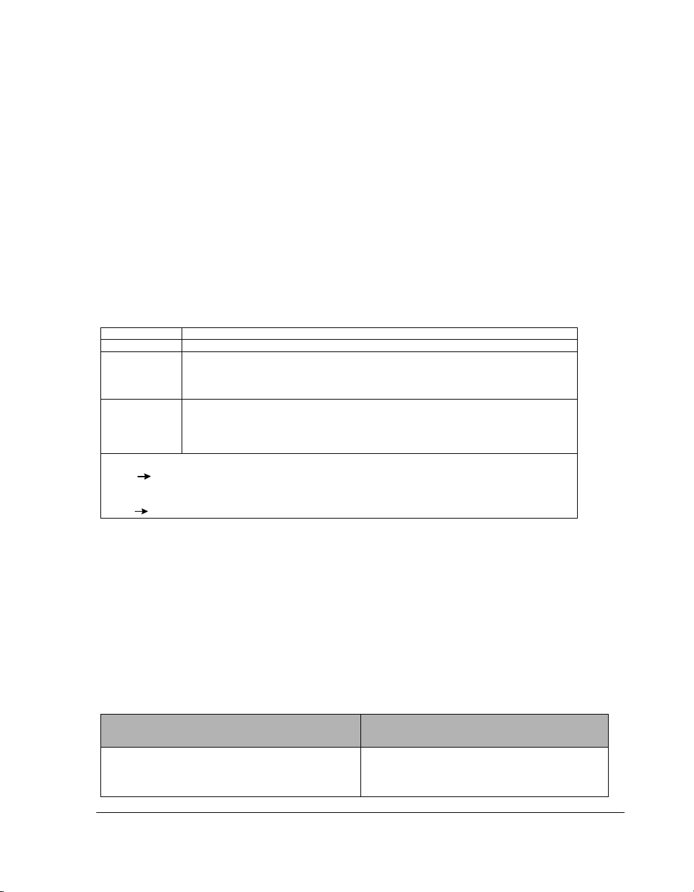
The following revisions are associated with this release.
Component Description
Hardware MIC Adapter Revision 4.2 or 4.3†
Firmware MIC BIOS Revision 4.0.61-SP
MIC MicroCode Revision 4.0.88-SP
Software English versions: Endurance Software Revision 4.0.1–SP.EA *
*
To confirm the revision of your Endurance software, from Endurance Manager select
View Revision Levels.
†
To confirm the revision of your Endurance software, from Endurance Manager select
View Revision Levels.
MIC FPGA Revision 4.2.59–SP
Endurance Manager Revision 4.0.62–SP.EA
Japanese versions: Endurance Software Revision 4.0.1–SP.JA*
Endurance Manager Revision 4.0.62–SP.EA
HP Netserver AA Solution Documentation
Endurance Release 4.0 documentation is available in hardcopy and online format. The online
documentation is located in the \
CD. Use Adobe Acrobat Reader Version 3 or Version 4 to read and/or print it.
The Release 4.0 documentation includes the following:
Manual or Document Format
README.txt Online only
Endurance Release Notes Online and hardcopy
Endurance Release Notes fo r Release 4. 0 Se rv ice Pack 1 1
Docs directory on the HP Netserver AA Solution Endurance
Table 1 Release 4.0 Documentation
Page 6

Table 1 Release 4.0 Documentation
Manual or Document Format
HP Netserver AA Solution Administrator’s Guide Online only
HP Netserver AA Solution Installation Guide Online only
HP Netserver AA Solution Messages Online only
Endurance Upgrade/Downgrade Procedures Online only
Glossary Online only and hardcopy in the HP
Netserver AA Solution Adminstrator’s Guide
Additional Documentation on the Customer Support Web Site
Note: This document contains complete and timely information about the product as of
its publication. However, you should consult the HP NetServer AA Solution Web
page at
http://netserver.hp.com/netserver/products/highlights_assured_avail.asp
to obtain the most recent updates to information about the release.
Platform Support and System Requirements
CE Dual Processor Support and CPU Requirement
Release 4.0 requires two processors in each CE, which are necessary for the server to boot. If
your server is configured with only one CPU in either of the CEs, the server will not boot. Also,
use of the
server will boot using both CPUs in the CE.
In addition, all processors in the CEs must be the same model (for example, Pentium
Pentium III Xeon
are the only supported CPU types.
2 Endurance Release Notes for Release 4.0 Service Pack 1
/onecpu switch in the boot.ini file has no effect; even if you set this switch, your
®
TM
) and speed. As of the initial Release 4.0, Pentium III or Pentium III Xeon
III or
Page 7

CE Configuration Requirements
Release 4.0 CEs must be configured identically, and must contain identical chipset versions to
avoid loss of CE synchronization when various system management tools are used. In
particular, the Add/Remove Hardware Wizard, Device Manager, and System Information tools
may cause the CEs to lose synchronization unless all of the following conditions are met:
Table 2 CE Configuration Requirements
Element Requirement
CE processors Must have the same model, stepping, and cache configurations.
CE BIOS revision Must match.
CE BIOS settings All configurable BIOS options must be identical (for example, serial and
parallel port settings, etc.).
CE add-in cards Card slot placements must match.
CE RAM The same DIMM slots must be occupied by DIMMS of the identical
manufacturer, type, and size.
Endurance Release Notes fo r Release 4. 0 Se rv ice Pack 1 3
Page 8

CE Motherboard BIOS Settings
Use the BIOS Setup Utility to verify that all onboard device settings between the two CEs are
identical. We strongly recommend that parallel, serial, SCSI, and network devices be disabled
on the CE.
Make sure that the following devices are enabled:
• Video adapter
• Keyboard
•Mouse
• 3.5-inch Floppy Disk — this can be disabled when it is not needed for maintenance
operations, such as flashing the BIOS.
In addition, the CE MICs must use the same IRQ and addresses, or the CEs will not be permitted
to synchronize.
On some systems, disabling of embedded devices is not allowed. Ensure that the embedded
devices that are still enabled on the CE motherboard use the same IRQ on both CEs. Not doing
so may result in a prompt from Windows requesting to reboot because a new device has been
installed.
In Windows 2000, if a device’s resource requirement changes between reboots, Windows will
recognize the device as a new device and install supporting software for the device. The
installation of supporting software may result in a prompt from Windows to reboot the system
because a new device has been installed. You may experience this behavior when the IRQ of
enabled embedded devices is not the same on both CEs.
This occurs because the responsibility for booting Windows may be on one CE during a boot
cycle, during which it presents the embedded devices with its assigned resources. But, on the
next boot cycle, the other CE may be responsible for booting Windows. In that case, it presents
the embedded devices with a difference set of assigned resources, causing Windows to
recognize the device as a new device.
Platform Support
The Endurance server supports only Pentium III or Pentium III Xeon processors on the CEs and
IOPs. However, use of the Pentium III serial number (PSN) is not supported in applications on
the CEs. For more updated information about additional platforms that are qualified to run
Endurance Release 4.0, refer to the HP Customer Support Web site.
4 Endurance Release Notes for Release 4.0 Service Pack 1
Page 9

Motherboard Requirement
The motherboards on all computers (CEs and IOPs) in the server must be capable of supporting
two or more processors.
Memory Requirement
An Endurance server requires a minimum of 256 MB of memory in the CEs and IOPs. In
addition, the server can support up to 4 gigabytes of memory in the CEs. There is no limit to
supported memory in the IOPs.
Marathon Interface Card (MIC) Requirement
An Endurance server requires the Marathon Interface Card (MIC) version 4.2 or 4.3. For best
performance in the IOPs, we recommend configuring the MIC with its own interrupt if possible,
rather than sharing an interrupt. Also, you should install the MIC in a primary PCI bus slot, and
not behind a secondary bridge chip.
If you plan to configure your server for extended long distance SplitSite, with tuples installed
up to 10 kilometers apart, you must use version 4.3 of the MIC. Refer to the section Marathon
Interface Card (MIC) 4.3 Available for information about this MIC and how to recognize
whether you have this version of the MIC.
Partition Format Requirement
Endurance Release 4.0 requires the use of NTFS partitions for all disks used in the server. Also,
the CE boot partition size is limited to 4000 megabytes. Refer to General Limitations for more
information about extending this partition size limit.
Operating System Requirements
In addition to the installation requirements listed in the HP Netserver AA Solution Installation
Guide, the operating system versions that are supported for Endurance Release 4.0 Service Pack 1
are described in Table 3.
Endurance Release Notes fo r Release 4. 0 Se rv ice Pack 1 5
Page 10

Table 3 Endurance Release 4.0 Service Pack 1 Supported Operating System Versions
Windows® Version
English Language Version — Windows and Endurance Software and Documentation
Windows 2000 Server CEs and IOPs Windows 2000 Service Packs 1 and 2
Windows 2000 Advanced Server CEs and IOPs Windows 2000 Service Packs 1and 2
Japanese Language Version — Windows and Endurance Software and Documentation
Windows 2000 Server CEs and IOPs Windows 2000 Service Packs 1 and 2
Windows 2000 Advanced Server CEs and IOPs Windows 2000 Service Packs 1 and 2
Endurance
Component
Supported Windows Service
Packs
Note: International customers other than those in Japan should use the English version
of Endurance software (Endurance software revision 4.0.1-SP.EA).
Endurance Enhancements in Release 4.0 Service Pack 1
Endurance Release 4.0 Service Pack 1 includes the following enhancements to the Endurance
software.
Support for Windows 2000 Service Pack 2
Release 4.0 Service Pack 1 introduces support for Windows 2000 Service Pack 2. If you choose
to install Windows 2000 Service Pack 2, you must be running Endurance Release 4.0.1-SP
software. Do not attempt to install Windows 2000 Service Pack 2 on any Endurance release
earlier than Release 4.0.1-SP.
If you choose to upgrade your Endurance server to use Windows 2000 Service Pack 2, you must
reboot the server after each installation, as follows:
Step Action
1 Install Release 4.0.1-SP Endurance software on your server CEs and IOPs.
2 Reboot your server.
3 Install Windows 2000 Service Pack 2 on your CEs and IOPs.
4 Reboot your server.
For additional information, refer to Endurance Upgrade/Downgrade Procedures on the
Endurance CD.
6 Endurance Release Notes for Release 4.0 Service Pack 1
Page 11

Support for Long Distance SplitSite® Distances Up to 10 Kilometers
As of Endurance Release 4.0 Service Pack 1, you can install the tuples up to 10 kilometers apart.
In order to configure your server with this SplitSite configuration, you must install Version 4.3
of the Marathon Interface Card (MIC), described in the next section.
Marathon Interface Card (MIC) 4.3 Available
MIC version 4.3 accommodates increased long distance SplitSite installations with tuple
separations of up to 10 kilometers. You can identify this version of the MIC by examining the
cable connector ports on the MIC. This version has blue plastic casing around the external part
of the Remote port, instead of the silver color that was used in the V4.2 MIC. The blue plastic
casing is visible from the rear of the server with the MIC installed.
Singlemode Fiber Support
MIC version 4.3 can use either singlemode fiber or multimode fiber for the Remote port. For
distances greater than 500 meters, you must use singlemode fiber. For distances of 500 meters
or less, you can use either singlemode fiber or multimode fiber. Table 4 and Table 5 describe
the cable specifications.
Table 4 Multimode Cable Ports
Fiber Size
(µm)
50/125 µm
62.5/125 µm
Fiber Type Maximum
Length
Multimode 500 Meters 500 Mhz*KM 5.5 dB MT-RJ
Multimode 200 Meters 200 Mhz*KM 4.5 dB MT-RJ
Minimum
Bandwidth at
850 nm.
Power Budget
End to End
Connector
Type
Table 5 Multimode Cable Ports
Fiber Size
(µm)
9/125 µm Singlemode 10KM NA 9 dB MT-RJ
50/125 µm
62.5/125 µm
Endurance Release Notes fo r Release 4. 0 Se rv ice Pack 1 7
Fiber Type Maximum
Length
**
Multimode
Multimode
**
Requires mode conditioning cables
500 Meters 500 Mhz*KM 5 dB MT-RJ
**
500 Meters 500Mhz*KM 5 dB MT-RJ
Minimum
Bandwidth at
850 nm.
Power Budget
End to End
Connector
Type
Page 12

Optional Endurance Kit Contents for 10 Kilometer SplitSite Configurations
If you have purchased the support for long distance SplitSite configurations of up to10 kilometer
separation of the tuples, the content of your Endurance kit is different from that described in the
Release 4.0 HP Netserver AA Solution Installation Guide.
Note: If you have not purchased the optional long distance SplitSite product, the content
of your Endurance kit is as described in the Release 4.0 HP Netserver AA Solution
Installation Guide.
For long distance SplitSite installations only, the Endurance Accessory Kit includes two
loopback plugs to be used if you want to perform BIOS loopback tests.
On page 1-14 of the Release 4.0 HP Netserver AA Solution Installation Guide, replace the
section Unpacking Your Endurance Server Kit with the following section applicable to long
distance SplitSite configurations. Changes from the previous version are shown in bold face.
Unpacking Your Endurance Server Kit
After Planning the SCSI Disk and CD-ROM Configurations, unpack your Endurance server kit
and make sure that you receive:
Table 6 Endurance Server Kit Contents
Quantity Part
4 MICs (Marathon Interface Cards)
4 MIC cables –2 local and 2 remote
Two fiber optic cables are 5 meters, and two are 10 meters
* in length.
* The 10 meter cables are used in long distance SplitSite installation for
staging purposes only.
1 IL (IOP Link) cable – Category 5 UTP cross-over (Ethernet) cable for use in fast
1
Ethernet connections, approximately 8 meters in length
IL (IOP Link) fiber – Multimode
Note: You use either of the above Ethernet connections, depending on whether
you have fast Ethernet or gigabit Ethernet.
* fiber for use in gigabit Ethernet, 8 meters in length
* The multimode fiber is used in long distance SplitSite installations for staging
purposes only.
1 Endurance CD-ROM
8 Endurance Release Notes for Release 4.0 Service Pack 1
Page 13

Quantity Part
Table 6 Endurance Server Kit Contents
1 Endurance documentation, including the Endurance Release Notes, HP Netserver AA
1 Endurance Accessory Kit that contains the labels for the Endurance server computers,
Solution Administrator’s Guide, and this manual
and two loopback plugs that enable you to perform the BIOS loopback tests if
you choose or need to do so.
Notes: For long distance SplitSite installations, you must obtain 4 singlemode
patch cords to connect the MICs to the patch panels. When obtaining
these patch cords, be sure that one end has the MT-RJ type of connector,
which attaches to the MICs. The other end of the patch cord can have
whatever type of connector (such as SC, FC, ST, or MT-RJ) will fit
your patch panel.
If you want to set up and test the Endurance server before installing
it in a long distance SplitSite configuration, use the standard cables
shipped with your Endurance server prior to long distance SplitSite
installation.
Using the labels from the Endurance server kit, apply the appropriate labels to the monitors,
front panels, and back panel of each IOP and CE. Use the loopback plugs if you perform
BIOS loopback tests.
Long Distance SplitSite Cabling Information
The following sections describe how to:
• Cable for loopback test
• Cable for staging purposes
• Cable long distance SplitSite installations
Endurance Release Notes fo r Release 4. 0 Se rv ice Pack 1 9
Page 14

Cabling for Loopback Tests
After completing the hardware installation, if you want to perform BIOS loopback tests, install
the loopback plugs as follows:
Step Action Notes
1 Remove the two loopback plugs from
the Endurance accessory kit.
2 Carefully remove the protective covers
from the loopback plugs.
3 Insert one plug into the REMOTE port
and the second plug into the LOCAL
port, gently pushing them in until you
hear a slight click.
4 Perform the BIOS loopback tests. Refer to Using the MIC BIOS Setup Utility
5 After loopback tests are complete,
remove the loopback plugs, as follows:
• Gently compress the arched fitting
located behind the rectangular
plastic box on the plug.
• After you hear a slight click, remove
the plug.
The local and remote ports of the V4.3 MIC use
different fiber optic wave lengths than those in
the V4.2 MIC, requiring the installation of plugs
into the individual ports for loopback testing.
starting on page 7-3 in the Endurance
Administrator’s Guide for information about
performing BIOS loopback tests.
After removing the plugs, carefully put the
protective covers back on the plugs.
10 Endurance Release Notes for Release 4.0 Service Pack 1
Page 15

Cabling for Staging Purposes in Long Distance SplitSite Installations
When staging the Endurance server for test purposes only, cable the MICs and IOP Link (IL)
as follows:
• MIC cables — Use the 2 local fiber optic cables and 2 remote fiber optic cables shipped in
your kit to connect the server components. The two different length cables shipped in
your kit are interchangeable when distance is not an issue during staging.
• IOP Link (IL) cables — Use the 2 multimode (SC to SC) cables to connect the two IL
Ethernet adapters.
On pages 2-6 and 2-7 of the Release 4.0 Installation Guide, after the section Cabling the
Endurance Server, add the section Cabling the Endurance Server for Long Distance SplitSite
Installation, and add Table 7 in this document, Long Distance SplitSite Endurance Server
Cables, as follows:
Cabling the Endurance Server for Long Distance SplitSite Installation
After Installing the MICs in the servers, connect the cables for long distance SplitSite
installations:
Step Action Notes
1 Remove the protective plugs from the
2 Plug in the two local fiber cables:
3 Use 4 singlemode patch cords (that you
4
En du ran ce Rel ea se N ot es for Re lea se 4.0 S er vic e P ack 1 11
cable sockets on the MIC and the
protective covers from the cables.
a. IOP1 to CE1
b. IOP2 to CE2
provide) to connect the MICs to your
patch panels.
Cable your network connection to each
IOP:
a. Attach an Ethernet cable (that you
provide) to the IOP’s network
adapter.
b. Connect the cable to your network
connection.
• Attach a cable connector to the IOP1 MIC
port labeled LOCAL and the other end of the
cable to the CE1 MIC port labeled LOCAL.
• Attach a cable connector to the IOP2 MIC
port labeled LOCAL and the other end of the
cable to the CE2 MIC port labeled LOCAL.
When attaching MIC cables, firmly seat the
connectors, and firmly push in the cable
assembly until it locks with a slight click. See
Table 7.
For the IL only, use 2 singlemode patch cords,
with SC type connectors, to connect the
singlemode gigabit network cards to the patch
panel.
Page 16

Table 7 explains how to install the long distance SplitSite Endurance server cables.
Table 7 Long Distance SplitSite Endurance Server Cables
Cable Description Connects Installation Instructions
MIC cables
4 singlemode patch
cords (that you obtain),
with an MT-RJ
connector on one end,
which attaches to the
MIC, and a connector at
the other end that will fit
the type of patch panel
you are using – for
example, an SC, FC, ST,
or LC connector.
IOP1 to CE2 via
the patch panel
CE1 to IOP2 via
the patch panel
IOP2 to CE1 via
the patch panel
CE2 to IOP1 via
the patch panel
1. A ttach an MT-RJ cable
connector on the singlemode
patch cord to the IOP1 MIC
port labeled REMOTE.
2. A ttach the other end of that
patch cord to the patch panel
port intended for CE2.
1. A ttach an MT-RJ cable
connector on the singlemode
patch cord to the CE1 MIC
port labeled REMOTE.
2. A ttach the other end of that
patch cord to the patch panel
port intended for IOP2.
1. A ttach an MT-RJ cable
connector on the single
mode patch cord to the IOP2
MIC port labeled REMOTE.
2. A ttach the other end of that
patch cord to the patch panel
port intended for CE1.
1. A ttach an MT-RJ cable
connector on the single
mode patch cord to the CE2
MIC port labeled REMOTE.
2. A ttach the other end of the
IOP1 patch cord to the patch
panel.
12 Endurance Release Notes for Release 4.0 Service Pack 1
Page 17

Table 7 Long Distance SplitSite Endurance Server Cables
Cable Description Connects Installation Instructions
IL Cable
2 singlemode patch
cords (that you obtain)
with SC connectors on
each end
IL singlemode
gigabit network
adapters on
IOP1 to IOP2 via
the patch panel
1. Attach one end of the patch
cord to the IL Ethernet
adapter port on IOP1 and th e
other end of the cord to the
patch panel.
2. Attach one end of the patch
cord to the IL Ethernet
adapter port on IOP2 and th e
other end of the cord to the
patch panel.
Be sure to connect the adapters
that support the IL and not the
adapters that connect your server
to the network.
Known Limitations
The following sections describe special Release 4.0 considerations, as well as the general and
third-party known limitations that have an impact on the Release 4.0 Endurance server.
Release 4.0 Considerations
CE Driver Signing Policy Considerations
The MtcPrep executable, part of the CE Unattended Installation, sets the Driver Signing Policy
for the CE operating system to Ignore in the Registry, and gives the user no warning notification
about this change.
Once you log in to the CE operating system for the first time and set up an Administrator
password, you can change file signature verification so that you are warned before unsigned
drivers are installed. To do so, follow these steps:
Step Action Notes
1
En du ran ce Rel ea se N ot es for Re lea se 4.0 S er vic e P ack 1 13
Select Start Settings Control Panel
System Hardware tab
.
Page 18

Step Action Notes
2In the Device Manager section, select Driver Signing.
3In the File signature verification section, click Warn,
and then OK.
Resetting this parameter to Warn
causes a message to be displayed
before any unsigned files are
installed.
Dynamic Disk Considerations
Release 4.0 supports the use of dynamic disks, as described below. To use dynamic disks with
the Release 4.0 Endurance software, consider the following:
• Consider using a basic disk for the CE boot disk. Some Windows 2000 resource kit items
do not support dynamic disks.
• Always use the Windows 2000 Disk Manager on the CE to create or update dynamic disks
and to write the disk signature. Do not create or update dynamic disks, write the disk
signature, or perform any dynamic disk operations on the IOPs. Managing volume
creation or extension from any environment other than the CE operating system will
produce unpredictable results and is not supported.
• You can perform the following disk management activities:
- Convert the CE boot disk and data disks from Basic to Dynamic. To do so,
perform the conversion on the CE operating system, not from an IOP in Offline
Endurance I/O Processor Mode.
- Create or extend volumes that span multiple redirected CE disks for volumes
created on the CE operating system.
- Configure CE data disks for simple volumes, spanned volumes, mirrored
volumes, striped volumes, or RAID volumes for disks created on the CE
operating system.
14 Endurance Release Notes for Release 4.0 Service Pack 1
Page 19

Performance Monitor Considerations
The Endurance Performance Monitor is not installed automatically as part of the standard
Endurance installation. If you elect to install it, you may see the following events in the
Application Event Log when Endurance performance counters are enabled:
The dat a bu ff er created fo r the "MtcPerf" service in the
"%SystemDrive%\Program Files\Marathon Endurance\MtcPerf.dll"
library is not aligned on an 8-byte boundary. This may cause problems
for applications that are trying to read the performance data buffer.
Contact the manufacturer of this library or service to have this
problem corrected or to get a newer version of this library.
The Open Procedure for service "Nbf" in DLL
"%SystemDrive%\WINNT\system32\perfctrs.dll" failed. Performance
data for this service will not be available. Status code returned is
data DW OR D 0.
Additional related events may also appear in your event log.
This is a known problem that occurs with Windows 2000 Service Pack 1. The problem also
occurs if other applications are used that install performance monitor plug-ins of their own, such
as SQL Server 7 or Exchange 5.5. The cause is currently unknown. We continue to investigate
the problem. For more information, refer to the Microsoft Knowledge Base article “Event ID
2033 Warning Message Logged When Loading Performance Monitor” at http://
support.microsoft.com/support/kb/articles/Q267/8/31.ASP.
If the above symptoms occur on your system, and you had installed the Endurance Performance
Monitor plug-in, consider uninstalling it. To do so:
Step Action Notes
1 Open a Command Prompt window.
2 Change to the Marathon Endurance Program files directory
> cd/d "%programfiles%\Marathon Endurance".
3 Type
En du ran ce Rel ea se N ot es for Re lea se 4.0 S er vic e P ack 1 15
MTCUPERF.
Alternatively, in Windows
Explorer, you could browse to
this directory and double-click
on
MTCUPERF.EXE.
Page 20

General Limitations
• CE boot partitions larger than 4000 megabytes are supported on some controllers. If your
environment requires a CE boot partition larger than 4000 megabytes, consider the
following:
- Endurance Release 4.0 software does not provide extended INT13 BIOS support.
Because of this, the size of the CE boot partition is restricted to sectors that can be
accessed via INT13 calls that use Cylinder/Head/Sector (CHS) mapping. In CHS
mapping, the maximum number of heads is 255; the maximum number of cylinders is
1023; and the maximum number of sectors per track is 63. Some controllers have
lower limits than these, with the maximum sectors per track often being limited to 32,
which creates a partition limit of 4000 megabytes.
- The IOP SCSI/RAID controller to which the CE boot disk is attached is the
component that determines the actual limit. If that controller supports 63 sectors per
track by default, or can be configured to support 63 sectors per track for the CE boot
disk, then you can have a partition size of 7.9 gigabytes. To use this partition size,
configure both IOPs to support 63 sectors per track. For some controllers, you can
choose between 2 gigabyte and 8 gigabyte support. Select 8 gigabyte support.
• Network connections may be lost temporarily during CE resynchronization. To minimize
the impact of such a loss, you can disable automatic synchronization. Then use a script to
schedule CE synchronization at a convenient time.
• After all steps in the CE Windows and Endurance Installation are complete, CE
motherboard devices that were detected during unattended setup will appear in Device
Manager with yellow warning circles. These devices have been disabled by the Endurance
software. You can ignore the yellow warning circles.
• The Endurance IOP installation procedure installs the IOP MIC driver programmatically
rather than using the Add/Remove Hardware Wizard. A consequence of this is that the
IOP MIC device appears in Device Manager under
Controller
with a yellow warning circle. You can ignore the yellow warning circle;
Other d evices as a Mass Storage
there is nothing wrong with the MIC device.
• The use of redirected floppy drives and redirected serial ports is not supported on Release
4.0.
• Release 4.0 supports only PS/2 interfaces for the redirected keyboard and mouse.
Redirected USB input devices are not supported.
• CEs in Release 4.0 must be configured identically, including CPU cache and steppings.
Refer to the section CE Configuration Requirements in these Release Notes for more
information.
16 Endurance Release Notes for Release 4.0 Service Pack 1
Page 21

• Dynamic recognition of hardware is not supported for any device redirected to the CE.
The CEs and IOPs must be rebooted to add or remove redirected devices.
• An Endurance server should never hibernate, be suspended, or automatically power down.
With the exception of an IOP monitor power down, Power Management requests will be
rejected by the Endurance software on the CEs and IOPs.
• As an integral part of the Endurance fault tolerant environment, the IOPs are dedicated I/O
processors that have an expected level of performance which must be maintained.
Endurance IOPs are intended to be used for running applications that monitor and manage
the Endurance server. If you run other utilities or applications that place a particularly
heavy load on the IOPs, it is possible that server elements (especially IOPs) may be
deconfigured if they can no longer provide the expected level of performance. This could
reduce overall system availability. Consequently you should not install and run
applications other than those that monitor and manage the server on the IOPs; instead, you
must install production applications on the CEs.
• The Endurance server does not support VGA mode on the CE.
•Do not use system BIOS features on CEs that require a local keyboard. Examples of these
features include screen blanking, power saving modes, and security modes, such as the
use of passwords or a security timer.
• Install the latest version of the Endurance Manager on remote clients that will be
monitoring any version of an Endurance server. You can use the Endurance Manager to
monitor prior Endurance releases, as described in Table 8.
Table 8 Installing Endurance Manager to Manage Remote Endurance Servers
Endurance Manager
Release 4.X Client*
Release 3.X Client
Release 2.X Client
*
*
Release 4.X
Server
Yes Yes Yes
No Yes Yes
No No Yes
Release 3.X
Server
Release 2.X
Server
Notes: Do not install a Release 4.0 Endurance Manager on a Release 3.X or Release 2.X
Endurance server.
En du ran ce Rel ea se N ot es for Re lea se 4.0 S er vic e P ack 1 17
*A client is a system with Endurance Manager software installed.
Page 22

Known Third-Party Vendor and Application Limitations
• As of the publication of this document, Windows 2000 does not support Complete
Memory Dump
2000 Service Packs 1 and 2. For more information, refer to the Microsoft Knowledge Base
article “Windows 2000 Does Not Enable Complete Memory Dumps Between 2 and 4
Gigabytes” at http://support.microsoft.com/support/kb/articles/Q274/5/98.ASP.
• Installation of pcAnywhere on your CEs can cause the CE operating system to crash. To
avoid the problem, override the default video mode (Accelerator mode) and specify
Compatibility mode. This behavior and a resulting workaround have been demonstrated
with versions 9.2, 9.21, and 10.0 of pcAnywhere.
• Endurance software may fail to shut down the system if the shutdown request occurs
before all system services have started. Because critical services and processes are not
started, Endurance software cannot shut down the system nor detect why it cannot shut
down the system. Wait until the system completes boot and all system services have
started before attempting to shut down the system.
• Applications with the following characteristics cause loss of CE synchronization:
- Applications or drivers that use Pentium hardware performance counters.
- Applications that install device drivers which directly check for local devices on the
CE may attempt to locate a product-key device, such as a dongle or specialized data
acquisition hardware.
with more than 2 GB of memory. This is a known problem as of Windows
• Applications using the following display functions may have unintended results on the
Endurance server:
- Color requirement other than 256 colors
- Resolutions greater than 1024x768
- Video BIOS (INT 10) calls
- Color mouse pointers and animated mouse pointers are not recommended.
- Full screen DOS mode
- Direct Draw interfaces
18 Endurance Release Notes for Release 4.0 Service Pack 1
Page 23

• Do not install any device drivers on the CEs that would replace or disable Endurance
drivers, such as:
- Remote control applications that replace Endurance video drivers with their own
video drivers.
- Video display drivers other than the Endurance Video Redirector (MtcVidR.sys).
• Debug tools that use drivers or have application code tied to hardware performance
counters may cause the server to hang or crash. Generally, by following these guidelines
you can avoid problems associated with debug tools:
- Do not run user-level debug tools such as WinDbg and Softice on the CEs.
- Do not use kernel mode (remote) debugging tools because they are not supported on
the CEs.
- Do not run development tools such as VTUNE (a performance application) on the
CEs.
Documentation Errata
The following information was incomplete or incorrect in the Release 4.0 manuals.
•In the HP Netserver AA Solution Installation Guide, on page 3-10, the manual instructs
you to rename all network adapters to correspond to their function in the Endurance
server. This section indicates you should rename the IL adapter, the Redirected Ethernet
adapters, the IOP Ethernet adapter, and the Virtual Network adapter.
The table should include a note that indicates the Virtual Network is not installed at this
point in the installation process. However, after the Virtual Network is installed, you
should rename the Virtual Network adapters as described.
•In the HP Netserver AA Solution Installation Guide, on page 3-5, under Step 2, the table
cell that describes the disk partition where you should install Windows for the IOP
neglects to state that you must install Windows on the C: drive on the first physical disk
on the IOPs. The IOP boot disk must be the C: drive.
En du ran ce Rel ea se N ot es for Re lea se 4.0 S er vic e P ack 1 19
Page 24

20 Endurance Release Notes for Release 4.0 Service Pack 1
 Loading...