

Page 1

HP Netserver AA S olution
Installation Guide
HP Part Number 5971-3015
Printed in April 2001
Page 2

NOTICE
The information contained in this document is subject to change without notice.
Hewlett-Packard makes no warranty of any kind with regard to this material, including, but not limited to, the
implied warranties of merchantability and fitness for a particular purpose.
Hewlett-Packard shall not be liable for errors contained herein or for incidental or consequential damages in
connection with the furnishing, performance, or use of this material.
Hewlett-Packard assumes no responsibility for the use or reliability of its software on equipment that is not
furnished by Hewlett-Packard.
This document contains proprietary information that is protected by copyright. All rights are reserved. No part
of this document may be photocopied, reproduced, or translated to another language without the prior written
consent of Hewlett-Packard Company.
TRADEMARK NOTICE
Assured Availability, ComputeThru, Computing for the long run, Constant Computing, Endurance, Marathon
Assured, MIAL, SplitSite, and the Marathon logo are either registered trademarks or trademarks of Marathon Technologies Corporation in the United States and/or other countries.
Microsoft, MS-DOS, Windows, Windows NT, and Windows 2000 are either registered trademarks or trademarks of
Microsoft Corporation in the United States and/or other countries.
All other brands and product names are trademarks of their respective companies or organizations.
SOFTWARE REVISION
The revision of the Endurance software that this document supports is Revision 4.0.0-RL.EA.
Hewlett-Packard Company
Network Server Division
Technical Communications MS 45SLE
10955 Tantau Avenue
Cupertino, California 95014 USA
ã Copyright 2001, Hewlett-Packard Company
ii
Page 3

Contents
Preface
Chapter 1 — Preparing for the Installation
Overview of the Endurance Server . . . . . . . . . . . . . . . . . . . . . . . . . . . 1-2
Endurance Manager . . . . . . . . . . . . . . . . . . . . . . . . . . . . . . . . 1-4
Fault Detection and Event Reporting . . . . . . . . . . . . . . . . . . . . . . . 1-4
Installation Requirements . . . . . . . . . . . . . . . . . . . . . . . . . . . . . . . . 1-6
Planning the SCSI Disk and CD-ROM Configurations. . . . . . . . . . . . . . . . . 1-9
Unpacking Your Endurance Server Kit. . . . . . . . . . . . . . . . . . . . . . . . 1-14
Completing Initial Power-On Self Test . . . . . . . . . . . . . . . . . . . . . . . . 1-15
Chapter 2 — Installing the Hardware
Installing the Adapters in the IOPs . . . . . . . . . . . . . . . . . . . . . . . . . . . 2-2
Installing the Adapters in the CEs . . . . . . . . . . . . . . . . . . . . . . . . . . . 2-4
Cabling the Endurance Server . . . . . . . . . . . . . . . . . . . . . . . . . . . . . 2-6
Completing Hardware Installation . . . . . . . . . . . . . . . . . . . . . . . . . . . 2-9
Chapter 3 — Installing Windows and the Endurance Software
Overview of Endurance Installation . . . . . . . . . . . . . . . . . . . . . . . . . . 3-2
Installing Windows and Endurance Software on the IOPs . . . . . . . . . . . . . . . 3-3
Installing Windows on the IOPs . . . . . . . . . . . . . . . . . . . . . . . . . . 3-4
Installing Endurance Software on the IOPs . . . . . . . . . . . . . . . . . . . . 3-8
Installing Windows and Endurance Software on the CE . . . . . . . . . . . . . . . 3-23
Installing the Endurance Manager on a Remote Client. . . . . . . . . . . . . . . . 3-34
Contents iii
Page 4

Appendix A — Adding a KVM or Video Switch to the Hardware
Considerations . . . . . . . . . . . . . . . . . . . . . . . . . . . . . . . . . . . . . A-2
Basic Requirements . . . . . . . . . . . . . . . . . . . . . . . . . . . . . . . . . . A-3
Examples of an Endurance Installation with a Video or KVM Switch . . . . . . . . A-4
Index
iv HP Netserver AA Solution Installation Guide
Page 5

Tables
1-1 Endurance Components . . . . . . . . . . . . . . . . . . . . . . . . . . . . . . . 1-2
1-2 Endurance Server Hardware Requirements . . . . . . . . . . . . . . . . . . . . . 1-6
1-3 Endurance Server Software Requirements. . . . . . . . . . . . . . . . . . . . . . 1-8
1-4 Endurance Server Kit Contents . . . . . . . . . . . . . . . . . . . . . . . . . . 1-14
2-1 Endurance Server Cables . . . . . . . . . . . . . . . . . . . . . . . . . . . . . . 2-7
3-1 Network Adapter Bindings. . . . . . . . . . . . . . . . . . . . . . . . . . . . . 3-12
Tables v
Page 6

Page 7

Figures
1-1 Sample Endurance Hardware Configuration . . . . . . . . . . . . . . . . . . . . 1-3
1-2 Sample SCSI Configuration Chart . . . . . . . . . . . . . . . . . . . . . . . . .1-10
1-3 SCSI Configuration Chart . . . . . . . . . . . . . . . . . . . . . . . . . . . . . . 1-12
2-1 Endurance Server Cabling . . . . . . . . . . . . . . . . . . . . . . . . . . . . . . 2-8
3-1 IL Adapter Bindings . . . . . . . . . . . . . . . . . . . . . . . . . . . . . . . . . 3-14
3-2 Redirected Ethernet Adapter n Bindings . . . . . . . . . . . . . . . . . . . . . . 3-14
3-3 Virtual Network Provider Adapter IOP1 Bindings . . . . . . . . . . . . . . . . .3-15
3-4 IOP Ethernet Adapters . . . . . . . . . . . . . . . . . . . . . . . . . . . . . . . 3-15
3-5 Endurance Configuration Utility. . . . . . . . . . . . . . . . . . . . . . . . . . 3-16
3-6 Example of Properly Partitioned Disks . . . . . . . . . . . . . . . . . . . . . . . 3-21
A-1 Hardware Configuration with a Video Switch . . . . . . . . . . . . . . . . . . . A-4
A-2 Hardware Configuration with a KVM Switch for Each Tuple . . . . . . . . . . . A-5
A-3 Hardware Configuration with a KVM Switch for Both Tuples in a Single Rack . . A-6
Figures vii
Page 8

Page 9

Preface
This guide describes how to install the HP Netserver AA Solution Enduranceâ server, the
Assured Availability
Audience
This guide is written for experienced network administrators and technical personnel
responsible for installing, configuring, administering, and managing network server hardware
and software, including Microsoft
This guide assumes that you are familiar with the Endurance terminology described in the HP
Netserver AA Solution Administrator’s Guide.
Documentation Set
The Endurance documentation set includes:
• HP Netserver AA Solution Installation Guide that describes how to install your Endurance
server.
ΤΜ
solution from the Hewlett-Packard Company.
â
Windowsâ.
• HP Netserver AA Solution Administrator’s Guide that describes the Endurance server and
its related Endurance applications. This guide also includes information about how to
monitor and manage your Endurance server.
• HP Netserver AA Solution Messages that lists and describes all Endurance messages. HP
Netserver AA Solution Messages is not shipped in printed form. It is only available online
using the HP Netserver AA Solution Endurance CD-ROM.
• Endurance Release Notes that describes release-specific information, including
installation requirements, operational information, and known product limitations that are
not documented in the HP Netserver AA Solution documentation set. You should read the
Release Notes before installing and using the Endurance server.
Preface ix
Page 10

All the documentation is available online using the HP Netserver AA Solution Endurance CDROM that was shipped with your HP Netserver AA Solution kit.
Conventions
The following conventions are used in the Endurance server documentation set:
Convention Description
Italics,
Courier font
Bold, Courier
font
Courier font Represents examples of screen text. For example, scsiid = 0, 1.
Bold Is used to:
Italics Is used to:
Blue text (Available only in online documentation.) Indicates a hyperlink (cross-reference
Caution Is used to indicate procedures you should not perform or situations you should
Warning Is used to indicate procedures or actions that could cause file or data corruption,
Indicates a variable that you replace in a path name or command
Indicates actions or commands that you must type. For example, type A:\ETX
• Emphasize important information.
• Indicate menu, pathname, or button selections.
• Indicate actions you perform.
• Highlight the state of the Endurance server component.
• Refer to manual, chapter, or section titles.
to another section of the Endurance documentation set). Clicking on the link
takes you to the appropriate place in the documentation set.
avoid in order to avoid personal injury.
loss of data, or damage to server components.
Unless noted otherwise, all cross-references are to chapters and pages within this book.
x HP Netserver AA Solution Installation Guide
Page 11

For Customer Support
Refer to the Warranty & Support for Your HP NetServer booklet supplied with your NetServer
for information relating to warranty or customer support.
Preface xi
Page 12

xii HP Netserver AA Solution Installation Guide
Page 13

Preparing for the
Installation 1
This chapter describes hardware and software requirements needed to install the Endurance
server. It also discusses what you need to do to prepare your site.
This chapter also introduces you to some Endurance terminology and concepts (described in
detail in the HP Netserver AA Solution Administrator’s Guide).
This chapter includes the following sections:
Overview of the Endurance Server . . . . . . . . . . . . . . . . . 1-2
Installation Requirements . . . . . . . . . . . . . . . . . . . . . . 1-6
Planning the SCSI Disk and CD-ROM Configurations . . . . . . . 1-9
Unpacking Your Endurance Server Kit . . . . . . . . . . . . . . .1-14
Completing Initial Power-On Self Test . . . . . . . . . . . . . . .1-15
Preparing for the Installation 1-1
Page 14

Overview of the Endurance Server
The fault tolerant Endurance server provides continuous computing and fully-redundant I/O
devices for your Microsoft Windows operating system and its applications.
The main Endurance components include:
Table 1-1 Endurance Components
Components Description
2 Compute Elements (CEs) The systems that provide all compute processing. The CEs run the
2 I/O Processors (IOP)s The systems that provides I/O resources, including I/O processing,
4 Marathon Interface Cards
(MICs)
operating system where you install and execute all applications.
data storage, and network connectivity.
The PCI-based adapters that enable bidirectional communication
between system components.
The Endurance technology coordinates all I/O requests and responses between the CEs and
IOPs in a redundant processing environment. Using redundant CEs and memory, the Endurance
software performs CPU and memory functions in a tightly coupled manner. If there is a CPU or
memory failure, the Endurance operating system remains continuously available, providing
constant computing without any loss of context.
Figure 1-1 depicts a sample hardware configuration of the Endurance server.
1-2 HP Netserver AA Solution Installation Guide
Page 15
Tuple 1
Tuple 2
CE
IOP
Figure 1-1 Sample Endurance Hardware Configuration
Device Redirection
CE
MIC cable
MIC cable
IOP
IL cable
To the network
Because all I/O devices in the server physically reside on the IOPs, Endurance software
redirects all I/O requests from the CEs to the IOPs. As a result, these I/O devices are logically
associated with the CE. For example, the Endurance software can redirect a CD-ROM drive
physically located in an IOP so that it is logically assigned to the CE (the CE has complete
control of that CD-ROM drive).
For mirrored disk devices and redundant Ethernet connections, the Endurance software
coordinates all I/O processing so that these redundant components appear as a single logical
device. For example, in a mirrored disk set, the two physical disks (one on each IOP) appear to
the CE operating system and applications as one logical disk. If a disk failure occurs, the disk
operations can transparently continue operating without affecting any server applications or
clients.
Preparing for the Installation 1-3
Page 16

Redirected Video and the CE Desktop Application
In the Endurance server, CE video output is redirected to the IOPs. To accomplish video
redirection, the server uses kernel mode drivers and the CE Desktop application, an application
that runs on the IOPs and displays CE video output in a window on the IOPs. To display CE
video, you must run the CE Desktop application.
Virtual Network
The Endurance server includes a virtual network that provides LAN-style connectivity between
the CEs and each IOP. This connectivity is independent of any public (redirected) CE or private
(IOP) network adapters. It uses the Windows operating system resource sharing to provide
connectivity between the CEs and IOPs regardless of whether the IOPs have dedicated network
cards installed.
Endurance Manager
The Endurance Manager is a management application for the Endurance server. This
application provides both a Windows-based GUI and a command prompt interface through
which you can monitor and manage your server. You can install the Endurance Manager on a
remote client, enabling you to monitor the system from another location.
Endurance Configuration Utility
The Endurance Configuration Utility enables you to define the Endurance server’s hardware
configuration and to store that configuration information in the appropriate locations of the
Windows Registry. You use the Endurance Configuration Utility to configure the server
initially, and also after making any changes to the Endurance server hardware configuration.
Fault Detection and Event Reporting
Endurance software continuously monitors the server. If it detects a fault, the Endurance server
isolates the fault and deconfigures any affected components, ensuring that the server remains
operational by automatically using the redundant components.
The fault detection and reporting process occurs seamlessly, and in a fully operational
Endurance server, it maintains complete server availability. The Endurance software reports all
events, including general status, state changes, and faults, to the Windows event logs or displays
them in windows as they occur. Refer to HP Netserver AA Solution Messages for complete
1-4 HP Netserver AA Solution Installation Guide
Page 17

documentation of Endurance messages, which use the standard Windows operating system
event format. Because the Endurance server uses standard message reporting, you can
integrate standard applications to notify you when a fault occurs.
Preparing for the Installation 1-5
Page 18

Installation Requirements
To complete the Endurance installation, you need to meet the hardware, software, and other
requirements described in the following sections:
• Hardware Requirements
• Software Requirements
Hardware Requirements
To install the Endurance server, you need the following hardware:
Table 1-2 Endurance Server Hardware Requirements
Item Notes
IOPs
The two IOPs must be Pentium® class PCI-bus PCs. Each IOP
must have:
• A minimum of 256 MB of system memory
• The capability of restarting automatically after a power failure.
On some systems, you may need to select options for automatic
restart in the system Setup utility.
• A SCSI system disk for the local copy of the version of the
Windows operating system you are using
• SCSI Host Based Adapter (HBA)
• One SCSI-based or IDE CD-ROM
• One SCSI IOP boot device (a physical drive or a logical drive
from a hardware RAID set)
• At least one SCSI hard disk that meets the requirements listed in
the Mirrored Disks Set(s) section of this table
•Two Ethernet Adapters that meet the requirements listed in the
Ethernet adapter section of this table
• Floppy disk drive
• Monitor, keyboard, mouse, and video adapter
Make sure your IOP systems conform with the requirements
specified in the Endurance Release Notes.
No IDE devices other than CD-ROMs may be present.
1-6 HP Netserver AA Solution Installation Guide
Page 19

Table 1-2 Endurance Server Hardware Requirements (Continued)
Item Notes
CEs The two CEs must be identical Pentium class PCI-bus PCs. Each
CE must have:
• The capability of restarting automatically after a power failure.
On some systems, you may need to select options for automatic
restart in the system Setup utility.
• Both CEs must have the same amount of RAM (256 MB
minimum).
• Floppy disk drive
• Video adapter -- required for the CE to boot and for
maintenance purposes. A standard PCI or AGP
VGA-compatible video adapter provides the video BIOS
required to boot the CE and display the following items:
- POST messages
- BIOS setup, test, and diagnostics
- MS-DOS boot for flashing the MIC
- Windows operating system flex-boot
- Text phase of the Windows operating system boot
• Monitor – used for running setup and diagnostics, flashing the
MICs on the CEs, and maintenance purposes.
• Keyboard – if your computer’s BIOS requires a keyboard to
boot.
Make sure your CE systems conform with the requirements
specified in the Endurance Release Notes.
You can use one monitor, keyboard, and mouse for the IOPs and
CEs along with a keyboard, video, mouse (KVM) switch. For more
information about using a switch as part of your hardware
installation, see Appendix A.
Mirrored Disks Set(s)
Preparing for the Installation 1-7
Each Endurance server configuration must have at least one
mirrored disk set (two disks, one on each IOP).
Page 20

Table 1-2 Endurance Server Hardware Requirements (Continued)
Item Notes
Ethernet Adapters At least four Ethernet adapters, minimally:
• Two Ethernet PCI adapters for the IOP Link (IL) connection (one
per IOP). These adapters must be identical – the same
manufacturer and model number. Cross-over cables are
provided with the Endurance server kit. If your adapters require
an alternative media type, be sure you acquire the appropriate
cable.
• Two Ethernet adapters (one per IOP) that support soft-settable
Ethernet addresses to provide connectivity to your network.
These adapters must be identical – the same manufacturer and
model number.
Refer to the HP Customer Support Web site for information
about the cables and adapters you can use in your Endurance
server.
2 or 3 blank diskettes Use two diskettes to make the Emergency Repair diskettes (one for
each IOP). If you choose to do so, you can also make an
Endurance Configuration diskette.
Network cables to provide
network connectivity
Optional: 2 Uninterruptable
Power Supplies
The cables must be compatible with the Ethernet adapters that you
install.
Use one UPS per tuple. The Endurance server has two tuples.
Each tuple contains a CE, and IOP, and a network connection.
Software Requirements
Make sure that you have all of the following before starting to install the software:
Table 1-3 Endurance Server Software Requirements
Item Notes
The Windows operating system Refer to the Endurance Release Notes for the Windows operating
One of the currently supported
Windows operating system
Service Packs
1 MS-DOS bootable diskette
systems on which the Endurance software can be installed.
New Service Packs, when available from Microsoft, may require
additional qualification from HP. For a complete list of supported
Service Packs, see the Endurance Release Notes
.
1-8 HP Netserver AA Solution Installation Guide
Page 21

Table 1-3 Endurance Server Software Requirements (Continued)
Item Notes
All device driver diskettes relating
to your computers and adapters
1 MIC utilities diskette Create this diskette using the instructions in Chapter 7 of the HP
For SCSI and Ethernet adapters, be sure to install the most current
driver. For most adapters, the driver that is shipped with the
adapter or that is packaged in the Windows operating system
distribution kit is not the most current.
One way to ensure you to obtain the most current driver is to
download it from the manufacturer’s web site.
If you are not sure you have the latest driver, contact the
manufacturer or your service provider for assistance.
Make sure that you know the path to the
diskette. Depending on the manufacturer, the driver might be
located in a subdirectory on the manufacturer’s diskette. For
example,
Netserver AA Solution Administrator’s Guide.
Warning: Make sure that the version of MTCFLASH you use
a:\winnt\.
coincides with your hotfix level. If you have a hotfix that
supersedes what is contained on the MIC utilities
diskette you created, use the hotfix diskette to flash the
MICs. In that case, do not use the MIC utilities diskette
you created from the Endurance CD.
.INF file on each driver
After reviewing the software installation requirements, read the Endurance Release Notes for the
Endurance software that you are about to install.
Continue with Planning the SCSI Disk and CD-ROM Configurations.
Planning the SCSI Disk and CD-ROM Configurations
After ensuring that you have all needed components, you must determine the SCSI device
configuration. You use this information when you configure the Endurance server software.
Complete a SCSI Configuration Chart (Figure 1-3) for your Endurance server. Copy this chart
if you need to complete more than one, which is necessary if you are using either:
• Multiple buses on a SCSI adapter
• Multiple SCSI adapters
A sample of a completed chart is shown in Figure 1-2.
Preparing for the Installation 1-9
Page 22

SCSI Configuration Charts
Sample SCSI Configuration Chart
PCI or other PC Bus Slot number: 1
1
SCSI Adapter Number (Port Number)
1
SCSI Bus Number
: 0
: 0
SCSI
1,2
ID
3
0
4
1
20Mirrored Disk
30Mirrored Disk
40CD-ROM N/A Must be unused N/A
50Must be unused N/A CD-ROM N/A
60Tape N/A Must be unused N/A
70Initiator ID N/A Initiator ID N/A
8 unused unused
9 unused unused
10 unused unused
11 unused unused
12 unused unused
13 unused unused
Logical
Unit
1
No
0 IOP1 Boot Disk IOP2 Boot Disk
0 CE Boot Disk
IOP1 Device Disk Size IOP2 Device Disk Size
(Mirrored Disk
Set 1)
Set 2
Set 3
CE Boot Disk
(Mirrored Disk
Set 1)
Mirrored Disk
Set 2
Mirrored Disk
Set 3
14 unused unused
15 unused unused
Note: Refer to the next page for notes and additional information.
Figure 1-2 Sample SCSI Configuration Chart
1-10 HP Netserver AA Solution Installation Guide
Page 23

Notes for the Sample SCSI Configuration Chart
1
This information is available in the active Windows Registry after you install all SCSI
adapters and the Windows operating system drivers
(HKEY_LOCAL_MACHINE\HARDWARE\DEVICMAP\SCSI).
2
One SCSI ID (typically 7) is not available because the SCSI adapter uses it. To determine
which SCSI ID is not available, check the adapter setup and identify the value of the
Initiator Id. Note that you can reset or change the Initiator Id for an adapter,
but it is not recommended unless you are doing this so that it matches its peer adapter on the
other IOP. Check the adapter vendor’s recommendations for this ID, or use SCSI ID 7 if
possible. Note that SCSI ID and Target ID are equivalent in meaning.
3
The IOP boot disk must be the first hard disk detected in the system configuration: lowest
adapter number (determined by the BIOS), lowest SCSI ID. In a typical single SCSI adapter
configuration, this is SCSI ID 0. Some SCSI adapters support booting from IDs other than
the lowest.
4
For the CE boot disk to map to the c: drive when the Endurance server is operational, the
CE boot disk must be the first redirected hard disk detected in the configuration: lowest
adapter number, lowest SCSI ID among redirected disk devices. In a typical (single SCSI
adapter) configuration, this is SCSI ID 1.
Additional Notes:
• IOP boot disks are not redirected to CEs and should occupy the same SCSI address on
both IOPs.
• CD-ROMS can be SCSI devices or IDE devices. All other storage devices (mirrored and
non-mirrored) must be SCSI devices. No IDE devices other than CD-ROMs can be
present in the IOPs. Note, however, that the Windows operating system treats IDE CDROMs like SCSI devices for configuration purposes.
• If you configure a non-mirrored device, the same corresponding SCSI address may not be
in use on the other IOP (same adapter number).
Preparing for the Installation 1-11
Page 24

SCSI Configuration Chart
PCI or other PC Bus Slot number:
SCSI Adapter Number (Port Number)
SCSI Configuration Chart
1
:
SCSI Bus Number
SCSI
ID
3
0
4
1
2
3
4
5
6
7
8
9
10
11
1,2
Logical
Unit No
1
:
IOP1 Device Disk Size IOP2 Device Disk Size
1
12
13
14
15
Figure 1-3 SCSI Configuration Chart
1-12 HP Netserver AA Solution Installation Guide
Page 25

Installing IDE CD-ROMS
You can install IDE CD-ROMs rather than SCSI CD-ROMs. If you install an IDE CD-ROM
drive in one IOP, then you must also install an IDE CD-ROM drive in the other IOP. No
variation on this hardware configuration is allowed.
Configure the IDE CD-ROM drive as necessary to be accessible by the Windows operating
system. If your server requires it, make sure that the IOP can boot from the IDE CD-ROM. You
can assign the IDE CD-ROM drive to the IOP operating system and not configure it as
redirected. You can also use the Endurance Configuration Utility to configure the IDE
CD-ROM drive for redirection, on either IOP1 or IOP2, but not on both.
If an IDE device malfunctions upon boot, the Windows operating system does not assign any
SCSI resources to the IDE controller. Moreover, if no IDE devices are detected, the ATAPI
driver is not loaded. This is different than SCSI devices, for which the Windows operating
system loads the SCSI driver and assigns port numbers as long as a SCSI adapter is detected,
even if no devices are attached to it.
Unless promptly repaired, an IDE CD-ROM failure results in different SCSI port number
assignments for all physical Host Based Adapters (HBAs) upon rebooting the IOP. This
invalidates the Endurance configuration for the IOP with the failed CD-ROM device, thus
preventing it from joining with the other IOP. In that case, the failed component must be
repaired before the IOP with the failed CD-ROM can return to active status.
Continue with Unpacking Your Endurance Server Kit (page 1-14).
Preparing for the Installation 1-13
Page 26

Unpacking Your Endurance Server Kit
After Planning the SCSI Disk and CD-ROM Configurations, unpack your Endurance server kit
and make sure that you receive:
Table 1-4 Endurance Server Kit Contents
Quantity Part
4 MICs (Marathon Interface Cards)
4 MIC cables –2 local and 2 remote
1 IL (IOP Link) cable – Category 5 UTP cross-over (Ethernet) cable for use in fast
1 IL (IOP Link) fiber – Multi-mode fiber for use in gigabit Ethernet, 8 meters in length
1 Endurance CD-ROM
1 Endurance documentation, including the Endurance Release Notes, HP Netserver AA
1 Endurance Accessory Kit that contains the labels for the Endurance server computers
Two fiber optic cables are 5 meters, and two are 10 meters in length.
Ethernet connections, approximately 8 meters in length
Note: You use either of the above Ethernet connections, depending on whether
you have fast Ethernet or gigabit Ethernet.
Solution Administrator’s Guide, and this manual
Using the labels from the Endurance server kit, apply the appropriate labels to the monitors,
front panels, and back panel of each IOP and CE.
Continue with Completing Initial Power-On Self Test.
1-14 HP Netserver AA Solution Installation Guide
Page 27

Completing Initial Power-On Self Test
After Unpacking Your Endurance Server Kit, complete the following for each computer:
Step Action Notes
1 Make sure the power switches for the
2 Following the manufacturer’s
3 Plug in the power cords. To increase fault resiliency, install the
4 Power on each computer; make sure
computer and monitor are off.
instructions, assemble each computer.
that it runs POST (power-on self test)
and boots properly.
computers of Tuple1 and Tuple2 on separate
AC power circuits using Uninterruptable Power
Supplies.
For the CEs, use a bootable floppy disk, and
ensure that the CEs boot.
For the IOPs, ensure that both IOPs can boot
from their respective hard drives. If an
operating system is not installed on the IOP,
use the MS-DOS boot diskette.
Continue with Chapter 2, Installing the Hardware.
Preparing for the Installation 1-15
Page 28

Page 29

Installing the Hardware 2
This chapter describes how to install the Endurance server hardware. This chapter assumes that
you are familiar with Endurance terminology (described in the HP Netserver AA Solution
Administrator’s Guide).
This chapter includes the following sections:
Installing the Adapters in the IOPs . . . . . . . . . . . . . . . . . 2-2
Installing the Adapters in the CEs . . . . . . . . . . . . . . . . . 2-4
Cabling the Endurance Server . . . . . . . . . . . . . . . . . . . 2-6
Completing Hardware Installation . . . . . . . . . . . . . . . . . 2-9
Installing the Hardware 2-1
Page 30

Installing the Adapters in the IOPs
After Completing Initial Power-On Self Test, install the Marathon Interface Card (MIC)
adapters, Ethernet adapters, and SCSI adapters in each IOP.
Warning: Make sure that both you and the computer are properly
grounded, using, for instance, a wrist strap with an attached
alligator clip that is connected to an appropriate ground.
Step Action Notes
1 Power off the IOP.
2 Remove the cover of the IOP following
the manufacturer’s instructions.
3 Install a MIC adapter in each IOP:
a. Carefully remove the MIC from its
anti-static packaging.
b. Install the MIC into an available PCI
slot.
4 Install the Ethernet adapters if not
already installed.
The MIC has no onboard jumpers or switches.
We recommend that MICs installed on IOPs be
installed in the same slot. For example, install
the MICs in slot 1 on both IOP1 and IOP2.
We recommend that MICs do not share IRQs
with other PCI devices, and whenever possible,
you should install MICs in a primary PCI bus.
We recommend that MICs and network cards
not be plugged in the same PCI bus as a SCSI
RAID controller.
Each IOP must have at least two, and may
have up to five, Ethernet adapters to support:
• An Ethernet PCI adapter for the IL
connection.
• An Ethernet adapter to provide connectivity
to your network.
These adapters must meet the requirements
described in Ethernet Adapters on page 1-8.
Ethernet adapter teaming and fault tolerance
(AFT) are not supported.
Make sure that you follow any installation
requirements imposed by the manufacturer. For
example, some adapter drivers must have a
unique IRQ.
2-2 HP Netserver AA Solution Installation Guide
Page 31

Step Action Notes
5 Install the SCSI adapters. If the SCSI adapter was not delivered already
6 Replace the cover.
7 Power on the IOP.
8 If the following BIOS options are
available for your SCSI adapter, ensure
that:
• Extended BIOS translation is
enabled for the SCSI adapter.
• BIOS support for Int13 extensions is
enabled for the SCSI adapter.
• Host Adapter BIOS is loaded.
• Scan BIOS on Boot is enabled only
for the CE boot disk and the IOP
boot disk.
9 Specify the identity of the MIC. The MIC BIOS Utility starts automatically
installed in your computer, using the information
that you recorded on the SCSI Configuration
Chart, install and configure the SCSI devices
following the manufacturer’s directions.
Make sure that you follow any installation
requirements imposed by the manufacturer. For
example, some adapters must have a unique
IRQ.
because the MIC does not have an identity
setting. Refer to Chapter 7 in the HP Netserver
AA Solution Administrator’s Guide.
Specify IOP1 or IOP2 to correspond with the
intended role of the IOP you are building.
10 Insert the MIC utilities diskette in the
floppy drive, and restart the IOP.
11 Run MTCFLASH to update the MIC
firmware: type MTCFLASH -f.
12 Remove the MIC utilities diskette.
For information about the MIC utilities diskette,
see page 1-9.
Warning: Once you start MTCFLASH, it must
run to completion without
interruption.
For more information about this utility, refer to
Chapter 7 of the HP Netserver AA Solution
Administrator’s Guide.
Continue with Installing the Adapters in the CEs.
Installing the Hardware 2-3
Page 32

Installing the Adapters in the CEs
After Installing the Adapters in the IOPs, install a MIC adapter in each CE.
Warning: Make sure that both you and the computer are properly
grounded, using, for instance, a wrist strap with an attached
alligator clip that is connected to an appropriate ground.
Step Action Notes
1 Power off the CE.
2 Remove the cover of the CE following
the manufacturer’s instructions.
3 Install a MIC adapter in each CE:
a. Carefully remove the MIC from its
anti-static packaging.
b. Install the MIC into an available PCI
slot.
4 Remove all devices except the
keyboard, video adapter, and floppy
drive.
5 Replace the cover of the computer.
6 Power on the CE.
7 Disable any disks in the computer
except for the floppy drive.
The MIC has no onboard jumpers or switches.
MICs installed on CEs must be installed in
the same slot location. For example, install
the MICs in slot 1 on both CE1 and CE2.
They must also have the same IRQ and use the
same PCI resources.
You should install the MIC in a primary PCI bus
slot whenever possible.
The initial installation of the CE software
requires a mouse.
Usually this is a 3.5’’ floppy drive. Refer to the
manufacturer’s setup documentation for
information.
Make sure that only the following devices are
enabled in the CMOS:
• Video adapter
• Keyboard
• Mouse for the initial CE installation
• 3.5’’ floppy drive
Permanently disable or remove all other
devices.
8 Use the BIOS setup utility to disable all
2-4 HP Netserver AA Solution Installation Guide
on-board SCSI, Ethernet, and IDE
controllers, parallel ports, COM ports,
and USB.
Page 33

Step Action Notes
9 Specify the identity of the MIC. The MIC BIOS Utility starts automatically
10 Insert your MIC utilities diskette in the
floppy drive, and restart the CE.
11 Run MTCFLASH to update the MIC
firmware: type MTCFLASH -f.
12 Remove the MIC utilities diskette.
whenever the MIC does not have an identity
setting. Refer to Chapter 7 in the HP Netserver
AA Solution Administrator’s Guide.
Specify CE1 or CE2 to correspond with the
intended role of the CE you are building.
Warning: Once you start MTCFLASH, it must
run to completion without
interruption.
For more information about this utility, refer to
Chapter 7 of the HP Netserver AA Solution
Administrator’s Guide.
Continue with Cabling the Endurance Server.
Installing the Hardware 2-5
Page 34

Cabling the Endurance Server
After Installing the Adapters in the CEs, connect the cables:
Step Action Notes
1 Remove the plugs from the cable
sockets on the MIC and the protective
covers from the cables.
2 Connect the cables supplied in the
Endurance kit.
3 Cable your network connection to each
IOP:
a. Attach an Ethernet cable (that you
provide) to the IOP’s network
adapter.
b. Connect the cable to your network
connection.
See Table 2-1
When attaching MIC cables, firmly seat the
connectors, and push the cable assembly in
firmly until it locks with a slight click.
Make sure that the CEs and IOPs are powered
on and the cable ends are plugged in. Then
verify that the LED adjacent to each connector
transitions to green.
Both IOPs must be directly connected to the
same local area network.
Make sure the Ethernet cable is:
• Compatible with the network cards that are in
use in IOP1 — 100 BASE-T (Twisted Pair) or
1.0 Gigabit (Fiber or Twisted Pair).
• The proper electrical specification (for
example, category 5 if 100 BASE-T).
If a smart HUB or Ethernet Switch is being used
as the Endurance server Ethernet rail
connection point:
• At the switch configuration level, enable
"Spanning Tree Protocol," or the equivalent
802.1d bridging protocol feature on each port
that will be connected to the Endurance
server.
• Set the correct port speed and duplex mode
(example 100Mbs/Full duplex) for each port
that will be connected to the Endurance
server. Do not select any Auto-detection
settings.
• If a "Fast Start" or equivalent parameter is
available, enable this feature for each port
that will be connected to the Endurance
server. This minimizes potential delays in
Ethernet fail-over performance.
.
2-6 HP Netserver AA Solution Installation Guide
Page 35

Table 2-1 Endurance Server Cables
Cable Description Connects Installation Instructions
MIC
Cables
IL Cable Category 5 UTP
2 local fiber optic
cables
2 remote fiber optic
cables
Note:
The 5 meter cables
are intended for
local use, while the
10 meter cables
are intended for
remote use.
However, the
cables are
interchangeable if
distance is not an
issue.
cross-over
(Ethernet) cable
OR
Fiber (gigabit
Ethernet) cable
IOP1 to CE1
IOP2 to CE2
IOP1 to CE2 1. Attach a cable connector to the IOP1 port
IOP2 to CE1
IL Ethernet
adapters on
IOP1 and
IOP2
1. Attach a cable connector to the IOP1 port
labeled LOCAL.
2. Attach the other end of the cable to the LOCAL
port on CE1.
1. Attach a cable connector to the IOP2 port
labeled LOCAL.
2. Attach the other end of the cable to the
LOCAL port on CE2.
labeled REMOTE.
2. Attach the other end of the cable to the
REMOTE port on CE2.
1. Attach a cable connector to the IOP2 port
labeled REMOTE.
2. Attach the other end of the cable to the
REMOTE port on CE1.
1. Attach one end of the cable to the IL Ethernet
adapter port on IOP1.
2. Attach the other end of the cable to the IL
Ethernet adapter port on IOP2.
Use the appropriate cable, depending on the type
of IL Ethernet adapter you have.
Be sure to connect the adapters that support the
IL and not the adapters that connect your server
to the network.
Installing the Hardware 2-7
Page 36

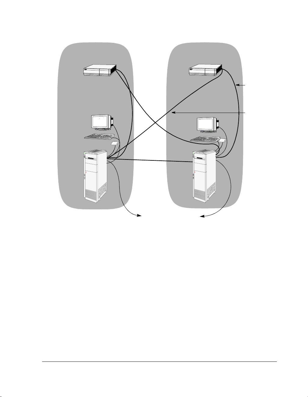
Figure 2-1 is a cabling example of the Endurance server. The figure includes monitors and
keyboards attached to the CE, which is an optional configuration.
CE
IOP
Tuple 1
Tuple 2
CE
MIC cable
MIC cable
IOP
IL cable
To the network
Figure 2-1 Endurance Server Cabling
For information about cabling the Endurance server with a KVM switch, see Appendix A.
Continue with Completing Hardware Installation.
2-8 HP Netserver AA Solution Installation Guide
Page 37

Completing Hardware Installation
To complete the hardware installation:
Step Action Notes
1 Power on the CEs and IOPs.
2 Verify that the MIC hardware is
operating properly by running the MIC
Client and Server Connectivity Tests
from the MIC BIOS Utility on each IOP
and CE.
Depending on the distance between the tuples,
completing these tests may require two people,
one at each tuple.
You need a keyboard and monitor on the IOP
and the CE to run tests in the MIC BIOS Utility.
For MIC BIOS Utility information, refer to
Chapter 7 of the HP Netserver AA Solution
Administrator’s Guide.
Continue with Chapter 3, Installing Windows and the Endurance Software.
Installing the Hardware 2-9
Page 38

Page 39

Installing Windows and the
Endurance Software 3
This chapter describes how to install the software for your Endurance server running the
Windows operating system. This chapter assumes that you are familiar with the Windows
operating system and Endurance terminology and describes only the Endurance-specific
information related to installing and configuring Windows. For detailed Windows operating
system information, refer to the Windows documentation.
To complete the software installation for the Endurance server, you must install both Windows
and Endurance software as described in the following sections:
Overview of Endurance Installation . . . . . . . . . . . . . . . . 3-2
Installing Windows and Endurance Software on the IOPs . . . . . 3-3
Installing Windows and Endurance Software on the CE . . . . . .3-23
Installing the Endurance Manager on a Remote Client . . . . . .3-34
Microsoft provides the capability to pre-apply Service Packs to the original Windows
distribution. This process is called Slip Streaming of Service Packs, and is explained by a
document on the Windows distribution media located at:
support\tools\spdeploy.doc.
In addition to working with standard Windows distribution kits, the Endurance installation will
work using kits prepared in this manner.
Installing Windows and the Endurance Software 3-1
Page 40

Overview of Endurance Installation
To complete an Endurance installation, you will follow this basic procedure:
Install Windows on IOP1.
(page 3-4)
Install Endurance software
on IOP1. (page 3-8)
Configure the network
software. (page 3-10)
Use the Endurance
Configuration Utility to
configure redirected
devices on IOP1.
(page 3-16)
Complete the post
installation tasks.
(page 3-19)
Partition and format the CE
disks. (page 3-19)
IOPs
Install Windows on IOP2.
(page 3-22)
Install Endurance software
on IOP2. (page 3-8)
Configure the network
software. (page 3-10)
Configure the devices on
IOP2 using the .cfg file
created on IOP1.
(page 3-16)
Complete the post
installation tasks.
(page 3-19)
Partition the CE disks.
(page 3-19)
Join IOP1 and IOP2.
(page 3-22)
CE
Run MtcPrep to prepare for
the Unattended Installation.
(page 3-23)
Allow the Unattended
Installation of Windows and
the Endurance software to
complete. (page 3-25)
Complete the Endurance
installation on the active
CE. (page 3-28)
Install the appropriate
Service Pack.
(page 3-28)
Configure the network
software. (page 3-29)
Adjust the Event Log
settings. (page 3-31)
Verify the Endurance
installation. (page 3-31)
3-2 HP Netserver AA Solution Installation Guide
Page 41

Installing Windows and Endurance Software on the IOPs
You install software on the IOPs by:
• Installing Windows on the IOPs
• Installing Endurance Software on the IOPs
• Completing the IOP Installation
Installing Windows and the Endurance Software 3-3
Page 42

Installing Windows on the IOPs
Before you begin, verify that the CE boot disks on the two IOPs are the same size. If the CE
boot disk on one IOP is smaller than that on the other IOP, consider the IOP with the smaller
CE boot disk IOP1 and begin installing your software there. Consider the other IOP, IOP2.
When the installation is complete, and the initial mirror copy is in progress, it copies from the
smaller disk, which should be IOP1, to the larger disk, IOP2.
Complete all procedures in this chapter in the order that they are documented.
Windows on the IOPs using one of the operating systems listed in the Endurance Release
Install
Notes.
3-4 HP Netserver AA Solution Installation Guide
Page 43

Step Action Notes
1 Start the Windows Setup, following the
manufacturer’s instructions.
2 Complete the Windows installation to
meet the requirements of your site, using
the following guidelines.
Windows Installation Guidelines for the Endurance IOPs
Have available the latest drivers for the
Ethernet adapters.
Check with your service provider for the
latest supported SCSI device driver for
your SCSI adapter.
When prompted for the disk partition
where you want to install Windows:
• Create the IOP’s boot partition of 1.5
gigabytes or larger.
• When you partition the IOP boot
device, reserve 1.5 gigabytes of
unpartitioned space at the end of the
disk for future use.
• Install the IOP Windows root in the
first partition.
Select NTFS as the file system format for
the IOP boot disk.
During network setup, include the IOP
number in the computer name.
These guidelines describe the tasks that you must
perform during the Windows installation for
Endurance IOP installation.
If you need detailed Windows installation
information, refer to the Windows documentation.
Windows should autodetect all SCSI drivers. If
you need additional SCSI drivers, you should
download them from the manufacturer’s web site.
Refer to Figure 3-6 for an example of a properly
partitioned disk.
• Be sure that you select the IOP boot disk.
• Also be aware that you cannot change the
boot drive letter once assigned.
NTFS is mandatory on all disks in the Endurance
server.
For example, NAME_IOP1
When configuring network adapters, be
sure to configure the Ethernet adapters
that service the IL to 100 Mbps or gigabit
and Full Duplex.
Do not install Microsoft Internet
Information Server on the IOP.
Specify the correct time for your
computer.
Installing Windows and the Endurance Software 3-5
This application is not supported on an IOP.
All Endurance server computers must use the
same time zone and daylight saving time option.
Later, when installing software on the CEs, the
time for the CEs is set to the time zone you
specified for the IOPs.
Page 44

Step Action Notes
3 Reboot the computer. A Windows Configure Your Server screen
appears.
• Select the Configure This Server Later
option.
• Click Next.
• Uncheck the option Show This Screen At
Startu p.
• Dismiss the screen.
4 Dismiss the Hardware Installation
Wizard.
5 Install one of the currently supported
Windows Service Packs and any
applicable Microsoft hotfixes.
6 Using the Backup utility, create an
Emergency Repair Diskette.
The Hardware Installation Wizard reports it
detected the IOP MIC as a mass storage
controller.
You will install the MIC driver later, during the
Endurance software installation on the IOP.
For a complete list of supported Service Packs,
refer to the Endurance Release Notes.
If you used slip streaming, ignore this step.
• Click Start Programs Accessories
System Tools Backup.
• In the Backup Utility, click the button for the
ERD, and enable Backup Registry to Repair
Directory.
Setting the Video Display Properties
For convenience and best performance, set the video properties on the IOP. Among the ways to
access video properties, you can either:
•Click Start Settings
Control Panel Display Settings tab on the Display
Properties Window
or
• Right click with the cursor located in the middle of the screen and click Properties.
3-6 HP Netserver AA Solution Installation Guide
Page 45

Set video and monitor resolutions to values that are supported by your video card and monitor:
• Number of colors – Color must be set to High Color or 16 bit (must be greater than 256
colors).
• Screen Area: 1024 X 768, or your personal preference.
• Refresh rate: 72 Hz or better, or your personal preference. (Click on Advanced, and then
select the Monitor tab to access the Refresh rate field.)
Continue with Installing Endurance Software on the IOPs.
Installing Windows and the Endurance Software 3-7
Page 46

Installing Endurance Software on the IOPs
After installing Windows on IOP1, install the Endurance software on IOP1. After you complete
the installation of Endurance software on IOP1, install the Windows and Endurance software
on IOP2.
Step Action Notes
1 Insert the Endurance CD in the
2 Follow the instructions displayed on the
3 When asked to choose the type of
CD-ROM drive of IOP1. At the top level
of the CD, navigate to and double-click
Setup.exe to start the installation
on
procedure.
screen.
setup, select Endurance Setup and
Online Documentation.
During the Endurance system setup portion of
the installation:
• Type the kit license number, which is located
on the back of the Endurance CD jewel
case.
•Select IOP1 (or IOP2 as appropriate) as the
location in which to install Endurance
software.
The Endurance Setup includes the installation
of the Endurance Manager.
During the online documentation portion of the
installation, install Adobe Acrobat Reader if it is
not already installed on your system.
The Endurance installation detects whether the
Adobe Acrobat Reader is installed. If it is
already installed, this option is displayed
without a check mark.
We recommend installing and reading the
online documentation on the IOPs
.
4 When prompted to restart the computer,
reboot the IOP in Offline Endurance I/O
Processor Mode.
Continue with Enabling NetBEUI.
3-8 HP Netserver AA Solution Installation Guide
Page 47

Enabling NetBEUI
For maintenance purposes, you can enable a networking protocol for communication between
the IOPs (IL adapter), or an IOP and a CE (Virtual Network adapter). NetBEUI is adequate for
this purpose. If you do not want to use NetBEUI, use TCP/IP for this purpose.
By default, the Windows installation only installs the TCP/IP protocol. In order to use NetBEUI
over the IOP Link or Virtual Network, you must install it. If you do not want to use NetBEUI,
do not install it.
To install NetBEUI, follow these steps:
Step Action
1 Right click on My Network Places on the desktop, and select Properties.
2 Right click on any configured adapter, and select Properties.
3 Click Install, Protocol, Add, then select NetBEUI.
Continue with Installing Network Software on the IOPs.
Installing Windows and the Endurance Software 3-9
Page 48

Installing Network Software on the IOPs
Before you begin to install network software on the IOPs, rename all network adapters to
correspond to their function in the Endurance server. Later, when configuring Ethernet adapters,
this will make it easier for you to select the desired adapters from a list.
To rename your adapters, on the Network and Dial-up Connection screen, right click on each
adapter, and rename it. We recommend the following names:
Connection Name Description Notes
• IL adapter for the adapter that services the IOP
• Redirected Ethernet
adapter 1
• Virtual Network adapter IOP1 for the Virtual LAN between the IOP and
• IOP Ethernet adapter for any network adapter not configured
Link
for all Ethernet adapters that provide
public LAN connectivity for the CEs
CEs
for the IL or as a redirected adapter
There can be up to four
redirected Ethernet
adapters. Name them as
shown, consecutively:
1,2,3, and 4.
Name the Virtual
Network adapter in IOP1
as shown. Replace
IOP1 with IOP2 in the
name for the Virtual
Network adapter in
IOP2.
3-10 HP Netserver AA Solution Installation Guide
Page 49

To install network software:
Step Action Notes
1 Install the Endurance Virtual Network Provider as a network adapter
using the Add New Hardware Wizard.
a. Using the Control Panel, start the Add/Remove Hardware Wizard.
b. Click Add/Troubleshoot a device.
c. Select Add a new device.
d. Select No, I want to select the hardware from a list.
e. Select Network adapters, then Have Disk.
f. Browse to
drive\folder\system32\drivers\MtcPnP
to add the service:
Service File
Endurance Virtual Network Provider
(MtcVnP)
The wizard completes the installation of the Virtual Network Provider.
netmtcvnp.inf
drive\folder is
the drive and folder
where you installed the
IOP root. (You can find
this in the
%SystemRoot%
environment variable.
For example,
C:\WINNT
Note: Ignore the warning
and continue the installation.
2 Install the Endurance network services.
a. Right click on My Network Places on the desktop, then select
Properties.
b. Right click on any configured adapter, and select Properties.
c. Click Install, Service, Add, then Have Disk.
d. Browse to
Digital Signature Not Found,
drive\folder\system32\drivers\MtcPnP to add the
services:
Service File
Endurance Datagram Service (MtcDgs
Endurance Ethernet Provider (MtcEthP netmtcethp.inf
Endurance IOP Link Driver (MtcEtx netmtcetx.inf
3 Adjust the network bindings:
a. From the Properties page, select each adapter, then Properties.
b. Using the check boxes, make the necessary adjustments for the
network bindings.
See Table 3-1.
After installing the first
service, repeat steps C
and D two more times
to install the other two
services.
netmtcdgs.inf
Installing Windows and the Endurance Software 3-11
Page 50

Table 3-1 Network Adapter Bindings
Adapter Description Binding Configuration
IOP Link Adapter
(IL)
Redirected
Ethernet adapter
The Ethernet adapter that
services the IOP Link and
provides private network
connectivity between the
IOPs.
Any Ethernet adapters that
provide LAN connectivity
for the CEs.
Enable
- Endurance IOP Link Driver
- Endurance Datagram Service
- NetBEUI or TCP/IP
For the TCP/IP protocol, you must specify the
IP addresses because there is no DHCP
server.
- Client for Microsoft Networks
- File and Printer Sharing for Microsoft
Networks
Disable
- Endurance Ethernet Provider
See Figure 3-1.
Be sure the Ethernet adapters that service the IL
are configured to 100 Mbps or gigabit and Full
Duplex.
Enable
- Endurance Ethernet Provider
- Endurance Datagram Service
Disable
- IOP Link Driver
- All other services and protocols
See Figure 3-2.
3-12 HP Netserver AA Solution Installation Guide
Page 51

Table 3-1 Network Adapter Bindings (Continued)
Adapter Description Binding Configuration
Endurance Virtual
Network Provider
(MtcVnP)
IOP Ethernet
adapter
Virtual LAN between the
IOP and the CEs which
provides a private point-topoint network.
Any network adapter that is
not configured for the IOP
Link (IL) or as a redirected
adapter.
Enable
- NetBEUI or TCP/IP
For the TCP/IP protocol, you must specify the
IP addresses because there is no DHCP
server.
- Client for Microsoft Networks
- File and Printer Sharing for Microsoft
Networks
Disable
- Endurance IOP Link Driver
- Endurance Ethernet Provider
- Endurance Datagram Service
See Figure 3-3.
Enable
- Endurance Datagram Service
- NetBEUI or TCP/IP
- Client for Microsoft Networks
- File and Printer Sharing for Microsoft
Networks
Disable
- Endurance Ethernet Provider
- IOP Link Driver
See Figure 3-4.
Note: You can bind MtcDgs to a maximum of five Ethernet adapters.
Figure 3-1, Figure 3-2, Figure 3-3, and Figure 3-4 provide examples of the adapter binding
configurations.
Installing Windows and the Endurance Software 3-13
Page 52

Endurance IOP Link Driver
Endurance Ethernet Provider
Endurance Datagram Service
NetBEUI or TCP/IP
Client for Microsoft Networks
File and Printer Sharing for Microsoft Networks
Figure 3-1 IL Adapter Bindings
Endurance IOP Link Driver
Endurance Ethernet Provider
Endurance Datagram Service
NetBEUI and TCP/IP
Client for Microsoft Networks
File and Printer Sharing for Microsoft Networks
Figure 3-2 Redirected Ethernet Adapter n Bindings
3-14 HP Netserver AA Solution Installation Guide
Page 53

Endurance IOP Link Driver
Endurance Ethernet Provider
Endurance Datagram Service
NetBEUI or TCP/IP
Client for Microsoft Networks
File and Printer Sharing for Microsoft Networks
Figure 3-3 Virtual Network Provider Adapter IOP1 Bindings
Endurance IOP Link Driver
Endurance Ethernet Provider
Endurance Datagram Service
NetBEUI or TCP/IP
Client for Microsoft Networks
File and Printer Sharing for Microsoft Networks
Figure 3-4 IOP Ethernet Adapters
Installing Windows and the Endurance Software 3-15
Page 54

Continue with Using the Endurance Configuration Utility to Configure Redirected Devices.
Using the Endurance Configuration Utility to Configure Redirected Devices
To configure the redirected devices, follow these steps:
Step Action Notes
When configuring IOP1:
1
2 Use the Endurance Configuration Utility to define all
Click Start Programs Marathon
Endurance Endurance Configuration Utility.
Figure 3-5 Endurance Configuration Utility
devices that will be redirected from the IOPs to the
CE.
For detailed information about using the
Endurance Configuration Utility, see
Chapter 6 in the HP Netserver AA
Solution Administrator’s Guide.
The Endurance configuration data for
both IOPs must be identical except for
Ethernet addresses.
To properly define your configuration,
you must define all devices that are
available to the CE operating system.
This includes mirrored disk sets (two
disks containing identical data and
residing on separate IOPs), nonmirrored devices (tape drives, CD-ROM
drives, or non-mirrored disks) from both
IOP1 and IOP2, and network adapters.
3-16 HP Netserver AA Solution Installation Guide
Page 55

Step Action Notes
Endurance Configuration Guidelines
3 For disks:
1. Select a component.
2. Click Add.
3. Select the appropriate option for the device you
are adding:
• Non-mirrored on IOP1
• Non-mirrored on IOP2
• Mirrored (the default)
4. From the list, select the SCSI device you want
to configure. Then follow the displayed
instructions.
For other devices, such as redirected Ethernet
adapters:
1. Select a component.
2. Click Add.
3. Repeat this procedure for each device you
want to add, including CD-ROMs, network
adapters, and tape drives.
Optionally, you can identify a CD-ROM drive for use
by the CE.
Make sure you add all devices that you
want to be available from the CE
(including the non-mirrored devices on
both IOP1 and IOP2).
A minimal configuration includes one
mirrored disk set (that contains the CE
boot partition).
When configuring the CE’s boot disk,
which must be a mirrored disk, be sure
to check the Boot option on the Confirm
Add SCSI Screen. (This box is grayed
out for any device that is not a valid
boot device.)
A minimal configuration includes one
redirected Ethernet adapter.
You can redirect a CD-ROM drive for
direct use from the CE, or alternatively,
you can access it over the Virtual
Network.
Warning: A maximum of one IDE CD-
ROM drive from one of the
IOPs can be redirected.
After configuring all devices, select Commit. This saves the configuration changes. If
After committing the configuration, select Save As,
and save the configuration to a file which you can
use to configure the Endurance software on IOP2.
Installing Windows and the Endurance Software 3-17
you exit the Configuration Utility without
clicking Commit, your configuration is
not saved.
You can transfer the file over the IL after
both IOPs are running.
Page 56

Step Action Notes
Only when configuring IOP2:
1
2 Use the Configuration Utility to specify IOP2
Click Start Programs Marathon
Endurance Endurance Configuration Utility.
Ethernet addresses instead of IOP1, and configure
the network adapters. Optionally, you can open the
Configuration file you saved from IOP1 to configure
devices on IOP2:
1. Select Network Adapters.
2. From the list, select the Ethernet adapter you
want to configure.
3. Click Remove to delete the Ethernet adapter
address on IOP1.
4. Click Add, and select the appropriate adapter
on IOP2.
5. Repeat this procedure for each entry you see
under Network Adapters in the Endurance
Configuration Utility.
6. Select Commit.
Continue with Completing the IOP Installation.
The steps in this section apply only to
configuring IOP2. They are not
performed when configuring IOP1.
Except for the Ethernet addresses, on
each IOP the configuration files must be
identical; otherwise, the IOPs fail to
join, and the CEs cannot be booted.
3-18 HP Netserver AA Solution Installation Guide
Page 57

Completing the IOP Installation
The following tasks complete the software installation on the IOPs:
• Creating an Emergency Repair Diskette
• Partitioning and Formatting the CE Boot Disk
• Verifying the Proper Configuration of the IOP Link Adapters
• Installing Software on IOP2
Creating an Emergency Repair Diskette
Use the Backup utility to create an Emergency Repair Diskette:
• Click Start Programs Accessories System Tools Backup.
• In the Backup Utility, click the button for the ERD and enable Backup Registry to
Repair Directory.
Continue with Partitioning and Formatting the CE Boot Disk.
Partitioning and Formatting the CE Boot Disk
You must partition and format the CE boot device on both IOP1 and IOP2. It is not necessary
to partition and format the CE non-boot devices on the IOPs; you can partition and format them
later from the CE after the CE is installed and booted.
Note: You must be in Offline Endurance I/O Processor Mode to access the CE disks
from an IOP.
To partition and format the CE boot disk, follow these steps:
Step Action Notes
1 Run the Disk Management application. To do so, right click on My Computer
on the desktop; select Manage; click
Disk Management in the console tree
under Storage.
The Computer Management view
appears in the right-hand pane. See
Figure 3-6.
2 If the Write Signature and Upgrade Disk Wizard
appears, dismiss it by clicking Cancel.
Installing Windows and the Endurance Software 3-19
New disks or disks that have had a low
level SCSI format performed cause a
prompt to write a signature.
Page 58

Step Action Notes
3 If a red circle with a minus sign appears
superimposed on a disk icon, complete these steps:
a. Right click on the red circle, and select Write
Signature.
b. Click the check box for all disks that require a
signature.
c. Click OK.
d. Verify that the red circle has cleared and that the
word Basic appears under the disk icon(s).
4 Create and format the partition(s):
a. Right click on an unallocated space.
b. Select Create Partition.
The Create Partition Wizard runs.
c. Follow the instructions on the screen, making
sure that the CE boot partition does not exceed
4000 MB and that you select the NTFS file
system (the default). Also be sure you select
Primary Partition for the CE boot partition.
5 Right click on the CE boot partition, and select
Mark Partition Active.
6 See Figure 3-6 for an example of properly
partitioned disks.
Only Basic Disks are supported for CE
boot devices.
• NTFS is the only supported file
system.
• Due to limitations in some SCSI
controllers, the maximum
supported size for the CE boot
partition is 4000 MB.
• When formatting, assign a
descriptive label to the partition. For
example, for the CE boot partition,
assign a label such as CE_Boot.
You must complete this step for the CE
boot partition to be a bootable partition.
3-20 HP Netserver AA Solution Installation Guide
Page 59

Figure 3-6 Example of Properly Partitioned Disks
Continue with Verifying the Proper Configuration of the IOP Link Adapters.
Verifying the Proper Configuration of the IOP Link Adapters
Verify that when you configured the network adapters, the Ethernet adapters that service the IL
are configured to 100 Mbps or gigabit and Full Duplex.
Continue with Installing Software on IOP2.
Installing Windows and the Endurance Software 3-21
Page 60

Installing Software on IOP2
To install the Windows and Endurance software on IOP2:
Step Action Notes
1
2 Complete all the included tasks through Verifying the
Return to Step 1 in the section
on the IOPs
Proper Configuration of the IOP Link Adapters on page
page 3-21.
on page 3-4.
Installing Windows
Substitute references to IOP1
with IOP2 when completing these
tasks.
Continue with Ensuring that IOP1 and IOP2 Join.
Ensuring that IOP1 and IOP2 Join
After completing all installation tasks for IOP1 and IOP2, ensure that the IOPs join.
Step Action Notes
1 Boot both IOPs in Operational Endurance I/O
2
Processor Mode.
Click Start Programs Marathon
Endurance Endurance Manager,
Endurance Manager on IOP1 to make sure both
IOPs and all IOP devices come online.
and use the
• Network rails are dark green.
• Disk sources of mirror copies are
light green.
• Disk targets of mirror copies are
yellow.
Continue with Installing Windows and Endurance Software on the CE.
3-22 HP Netserver AA Solution Installation Guide
Page 61

Installing Windows and Endurance Software on the CE
After completing the IOP software installation, install Windows and Endurance software on the
CE by:
• Installing the Software on the CE
• Completing the Unattended Installation
• Completing Software Installation on the CEs
Installing the Software on the CE
Before you begin to install software on the CE:
• Attach a local keyboard, mouse, and monitor to the CE. You may need to use these if
problems are detected during the Unattended Installation.
• Installation of Windows and Endurance software on the CE is accomplished by the
Windows Unattended Installation. For this automatic installation, you must supply several
settings, such as:
- The Windows license type:
- Per server. If per server, indicate the number of auto users.
- Per seat
- The computer name
- The user name
- The organization name
- The Windows product ID
Note: If you are slip streaming the CE’s Service Pack, before installing Windows on the
CE, refer to the Microsoft documentation about slip streaming the Service Pack
for information about preparing the Windows installation. Once the Service Pack
is applied, it takes the place of the Windows distribution media.
Installing Windows and the Endurance Software 3-23
Page 62

To prepare for the Unattended Installation, follow these steps:
Step Action Notes
1 Using Endurance Manager, disable IOP2 and CE2. You can use the Tuple Disable
2 If you have the Windows bootable CD in the
3 Boot IOP1 in Offline Endurance I/O Processor
4
5 Specify the destination location for the CE’s copy of
CD-ROM, remove it.
Mode.
On IOP1, launch
the operating system.
MtcPrep.exe. MtcPrep.exe creates files that
Operation command for tuple 2.
If you have the Windows CD in the
drive, when you boot the computer in
Step 3, the Windows setup starts.
The default is Operational Endurance
I/O Processor Mode. Be sure to select
Offline Endurance I/O Processor Mode.
prepare the system for the Unattended
Installation of the Windows and
Endurance software on the CE.
The program is located in \Program
Files\Marathon Endurance\CE\Setup.
At this time, the information you provide
is accepted, and the preparation for the
installation proceeds.
However, if you entered an incorrect
Windows product key, later you will be
prompted for the correct one.
• Drive: Browse to the drive you
marked as the boot disk in the
Endurance Configuration Utility.
• Folder: Indicate the Windows folder.
Typically this is
WINNT.
6 Insert the Windows distribution media in the IOP
7 Answer all questions, providing information
8 After you answer all questions, check Begin CE
CD-ROM drive. On the Windows Distribution Media
screen, browse to the
applicable to your site, user, and operating system
licenses.
Windows installation now to run the CE Windows
installation immediately.
\i386 folder.
The Windows installation directory
contains the setup utility
WINNT32.exe, which copies the
Windows installation files to the CE boot
disk.
If the directory specified in Step 6 is not
correct, MtcPrep.exe cannot launch the
Unattended Installation setup correctly,
and an error appears on the screen.
In that case, verify the location of
WINNT32.exe and run
MtcPrep.exe again.
3-24 HP Netserver AA Solution Installation Guide
Page 63

Step Action Notes
9 Ensure that the automatic reboot of the IOP is in
Operational Endurance I/O Processor Mode (the
default).
10 Power on CE1. If you are using a KVM switch instead of
11 Allow the Unattended Installation on the CE to
complete.
After the Unattended Installation setup
copies the installation files to the CE’s
disk, the IOP reboots automatically.
a local keyboard, mouse, and monitor,
use the KVM switch to change the focus
to the CE.
This process can take up to an hour.
The CE reboots after text mode setup
and GUI mode setup complete.
Note: While software is being installed
on the CE, the computer time of
the IOPs is incorrect. When
Windows installation completes,
the time on the CEs and IOPs
synchronizes and is correct.
Also, the time zone for the CEs
matches that of the IOPs, which
you specified when installing
software on the IOPs.
Continue with Completing the Unattended Installation.
Installing Windows and the Endurance Software 3-25
Page 64

Completing the Unattended Installation
The procedure you follow to complete the Unattended Installation of the CE software is
dependent upon your specific hardware configuration.
For a KVM Switch
If your configuration contains a keyboard, video, mouse (KVM) switch with a port for each CE
and IOP, follow these steps to complete the Unattended Installation of the CE software:
Step Action Notes
1 Use the KVM switch in order to view the CE1 video. Select the port connected to CE1’s
keyboard, video, and mouse.
2 The Windows screen Configure Your Server should
3 Use the KVM switch to change focus to the IOP in
4
5 Using the Endurance Manager, invoke the
6 On the IOP, start the CE Desktop application. For information about the CE Desktop
be displayed.
order to view the IOP’s video.
From the application task bar, select Start
Programs Marathon Endurance
Endurance Manager to start the Endurance
Manager.
command CE_O/S Shutdown Operation from
IOPx, where x is the ID number of the IOP from
which you issue the command.
This occurs at the conclusion of step 11
of the previous section, up to one hour
after the start of the CE installation.
Viewing this screen indicates that Setup
has completed on the CE.
Select the port connected to IOP1’s
keyboard, video, and mouse.
The CE Endurance System
Management service initiates the
system shutdown.
application, refer to Chapter 3 of the HP
Netserver AA Solution Administrator’s
Guide.
Once the CE has rebooted, the video,
keyboard, and mouse are redirected to
the IOP.
3-26 HP Netserver AA Solution Installation Guide
Page 65

For a Monitor Attached Directly to the CE
If your configuration contains a monitor attached directly to the CE, follow these steps to
complete the Unattended Installation of the CE software:
Step Action Notes
1 View the CE video on the CE monitor.
2 The Windows screen Configure Your Server should
be displayed.
3 While viewing the IOP’s video, from the application
task bar, select Start Programs Marathon
Endurance Endurance Manager to start the
Endurance Manager.
4 Using the Endurance Manager, invoke the
command CE_O/S Shutdown Operation from
IOPx, where x is the ID number of the IOP from
which you issue the command.
5 On the IOP, start the CE Desktop application. For information about the CE Desktop
This occurs at the conclusion of step 11
of the previous section, up to one hour
after the start of the CE installation.
Viewing this screen indicates that Setup
has completed on the CE.
The CE Endurance System
Management service initiates the
system shutdown.
application, refer to Chapter 3 of the HP
Netserver AA Solution Administrator’s
Guide.
Once the CE has rebooted, the video,
keyboard, and mouse are redirected to
the IOP.
Continue with Completing Software Installation on the CEs.
Installing Windows and the Endurance Software 3-27
Page 66

Completing Software Installation on the CEs
Note: You do not install CE software on the second CE. The IOPs update the disks via
a mirror copy.
After the Windows Unattended Installation completes, the CE reboots, and video is redirected
to the CE Desktop application on the IOP. To view CE video output, you must ensure that
the CE Desktop application is running on the IOPs.
At this time, you will complete steps that could not be performed during the Unattended
Installation:
• Installing the Appropriate Service Pack on the CE
• Installing Networking Software on the CE
Installing the Appropriate Service Pack on the CE
Install one of the currently supported Windows Service Packs and any applicable Microsoft
hotfixes on the CE.
Note: Perform this step if you did not slip stream the Windows installation.
For a complete list of supported Service Packs, refer to the Endurance Release Notes.
Continue with Installing Networking Software on the CE.
3-28 HP Netserver AA Solution Installation Guide
Page 67

Installing Networking Software on the CE
To install the networking software, follow these steps:
Step Action Notes
1 On the CE, install the Endurance Ethernet
2 Repeat step 1 for the number of redirected
Redirector using the Add New Hardware
Wizard.
a. Using the Control Panel, start the Add/
Remove Hardware Wizard.
b. Click Add/Troubleshoot a device.
c. Click Add a new device.
d. Select No, I want to select hardware from
a list.
e. Select Network Adapters, then Have Disk.
f. On the CE boot drive, browse to
drive\folder\system32\drivers\
MtcPnP\netmtcethr.inf
g. Select Endurance Ethernet Redirector
(MtcEthR).
h. Ignore the warning Digital Signature Not
Found, and continue with the installation.
The installation for the Ethernet Redirector
completes.
Ethernet adapters that you have.
.
Perform these steps from within the CE
Desktop window on the IOP. You may
want to consider running the CE
Desktop in full-screen mode.
Installing Windows and the Endurance Software 3-29
Page 68

Step Action Notes
3 On the CE, install the Endurance Virtual
Network Redirector using the Add New
Hardware Wizard.
a. Using the Control Panel, start the Add/
Remove Hardware Wizard.
b. Click Add/Troubleshoot a device.
c. Click Add a new device.
d. Select No, I want to select hardware from
a list.
e. Select Network Adapters, then Have Disk.
f. On the CE boot drive, browse to
drive\folder\system32\drivers
\MtcPnP\netmtcvnr.inf.
g. Select Endurance Virtual Network
Redirector (MtcVnR).
h. Ignore the warning Digital Signature Not
Found, and continue with the installation.
The installation of the Virtual Network
Redirector completes.
4 Repeat step 3 to install a second Endurance
Virtual Network Redirector for IOP2.
You must install the Endurance Virtual
Network Redirector twice to create two
virtual network adapters: the first to
connect IOP1, and the second to
connect IOP2.
drive\folder is the drive and directory
where you installed the CE copy of
Windows. (You can find this in the
%SystemRoot% environment variable.
For example,
If using the TCP/IP protocol, you must
specify the IP addresses because there
is no DHCP server on the Virtual
Network.
Continue with Adjusting the CE and IOP Event Log Settings.
C:\WINNT.)
3-30 HP Netserver AA Solution Installation Guide
Page 69

Adjusting the CE and IOP Event Log Settings
To adjust the Event log settings, on the CE and on each IOP, right click on My Computer
Manage Event Viewer. On the Computer Management screen, click Properties to set the
options for each of the system, application, and security logs. For each log, set the Maximum
Log Size to at least 1024 KB, and enable Overwrite Events as needed.
Continue with Verifying the Endurance Server Installation.
Verifying the Endurance Server Installation
To verify the Endurance server installation:
Step Action Notes
1 On the online IOP, start the Endurance
Manager, and then use it to enable the
CE and IOP in the other tuple.
2 Use Endurance Manager to verify that a
mirror copy is in progress from IOP1 to
IOP2.
3 Using the Endurance Manager, issue a
Server Shutdown command.
4 After the CEs and IOPs completely shut
down, power cycle the CEs and the
IOPs.
The copy proceeds from the IOP on which you
performed the CE installation to the other IOP.
As described on page 3-4, you should have
begun the installation by installing the software
on the smaller of the disks, typically IOP1, and
the mirror copy would be from IOP1 to IOP2.
Installing Windows and the Endurance Software 3-31
Page 70

Step Action Notes
5 Make sure that all computers reboot
and that the CEs synchronize.
6 If necessary, start the CE Desktop
application on either IOP.
7 Click in the CE Desktop window and
login to the CE operating system.
8 Start Endurance Manager and make
sure that all Endurance server
components transition to active, online,
or standby.
• Both IOPs must be present for the
Endurance server to complete the boot
process.
Because all I/O devices (including the CE
boot disk with the CE operating system)
physically reside on the IOPs, the CEs do
not begin booting until both IOPs complete
their boot process and are available.
If the CEs are powered on at the same time
as the IOPs, the CEs complete their POST,
and then wait for the IOPs to complete their
boot process.
• After the IOPs complete their boot process,
the CEs boot: one CE loads the Windows
operating system; then the other CE is
synchronized so that both CEs perform all
CPU and memory functions in a tightly
coupled manner.
The CE Desktop application should start
automatically.
9 Using Endurance Manager, disable the
active Ethernet connection to make
sure that Ethernet access fails over
properly, and then re-enable the
disabled connection.
Alternatively, you can unplug the cable
from the active Ethernet connection, replug it in, and ensure that Ethernet
access fails over correctly.
3-32 HP Netserver AA Solution Installation Guide
Verify that client connections are not lost.
Page 71

SplitSite Installation
To install in a SplitSite configuration, starting at the site of Tuple1:
Step Action
1 Install all software (Windows and Endurance) on IOP1.
2 Use the Endurance Manager to disable CE1 and IOP1 (tuple 1).
3 Copy the Endurance configuration to a floppy disk.
4 Boot IOP1 in Operational Endurance I/O Processor Mode.
5 Use the Endurance Manager to partition the CE boot disk on IOP1.
6 Power on CE1.
7 Go to the site of Tuple 2.
8 Install all software (Windows and Endurance) on IOP2.
9 Load the Endurance configuration file from the floppy you created on IOP1.
10 Correct the Ethernet addresses for the IOP2 redirected network card.
11 Use the Endurance Manager to enable IOP1.
12 Verify that IOP1 joins successfully, and correct any problems.
13 Use the Endurance Manager to disable IOP1.
14 Boot IOP2 in Offline Endurance I/O Processor Mode.
15 Install the CE software as described in this manual, replacing references to CE1 with CE2,
16 Complete the CE software installation.
17 Use the Endurance Manager to enable IOP1.
18 Verify that IOP1 joins successfully.
19 Use the Endurance Manager to enable CE1.
20 Verify that CE1 synchronizes successfully.
and IOP1 with IOP2.
If it is necessary to complete a single tuple installation before you begin the installation on the
second tuple, simply skip the step of installing IOP2 before installing the CE software.
Note: The CE software is installed on only one CE. You can install the software on
either CE.
Installing Windows and the Endurance Software 3-33
Page 72

Installing the Endurance Manager on a Remote Client
This section describes how to install the Endurance Manager on a remote client. For Endurance
Manager information, including information about using Endurance Manager on a remote
client, refer to Chapter 4 in the HP Netserver AA Solution Administrator’s Guide.
You can use Endurance Manager on a remote client to monitor and manage an Endurance
server.
To install the Endurance Manager and the Endurance online documentation on a remote client:
Step Action
1 On the remote client, insert the Endurance CD in the CD-ROM drive. Run the Setup
2 Follow the instructions displayed on the screen, making sure that you select Endurance
executable.
Manager as the setup type. Optionally, you can also select the setup type Online
documentation to install the online documentation.
When the installation completes, you can use Remote Endurance Manager to monitor and
manage your Endurance server. Refer to Chapter 4 of the HP Netserver AA Solution
Administrator’s Guide for information.
What to Do Next
For information about Endurance server operational concepts and a system overview, refer to
Chapter 2 of the HP Netserver AA Solution Administrator’s Guide.
For information about how to use the Endurance Manager to monitor and manage your
Endurance server, refer to Chapter 4 of the HP Netserver AA Solution Administrator’s Guide.
3-34 HP Netserver AA Solution Installation Guide
Page 73

Adding a KVM or Video
Switch to the Hardware A
This appendix discusses adding a keyboard, video, mouse (KVM) switch to the hardware
installation, includes information about basic considerations and requirements, and provides
examples of installations that use KVM or video switches in an Endurance hardware
configuration.
This appendix contains the following sections:
Considerations . . . . . . . . . . . . . . . . . . . . . . . . . . . . A-2
Basic Requirements . . . . . . . . . . . . . . . . . . . . . . . . . . A-3
Examples of an Endurance Installation with a Video or KVM Switch A-4
Adding a KVM or Video Switch to the Hardware A-1
Page 74

Considerations
Each CE requires a standard VGA-compatible video adapter. The adapter provides the video
BIOS to boot the CE and is used to display the following items:
• POST messages
• BIOS setup, test, and diagnostics
• MS-DOS boot for flashing the MIC
• Operating system flex-boot
• Text phase of the operating system boot
• Initial CE installation
You can monitor and manage the IOPs and CEs from one location by adding a KVM or video
switch to your hardware configuration. Depending on your site’s physical layout and the
configuration of the hardware within the workspace, you can use a KVM or video switch in a
variety of ways. For example, you can purchase and install:
• A video switch if you want the IOP and CE in each tuple to share a monitor.
• A 2-channel KVM switch to alternate the monitor and keyboard between the IOP and CE,
if you install each tuple in its own rack.
• A single 4-channel KVM switch to alternate the monitor, keyboard, and mouse between
the IOPs and CEs if you install both tuples in one rack.
A-2 HP Netserver AA Solution Installation Guide
Page 75

Basic Requirements
When you purchase a KVM switch, you should consider the following requirements. The
switch:
• Appears to the computer as a physical keyboard and mouse.
• Simulates the keyboard, monitor, and mouse even when powered off.
• Supports VGA and SVGA high-resolution video.
Adding a KVM or Video Switch to the Hardware A-3
Page 76

Examples of an Endurance Installation with a Video or KVM Switch
This section contains illustrations of cabling the video or KVM switch. See Figure 2-1 for an
illustration of cabling the Endurance server.
This example shows a configuration of the hardware with a video switch so that the CE and IOP
in each tuple can share a monitor.
CE 1
Video
Switch
IOP1
Tuple 1
CE 2
Video
Switch
IOP 2
Tuple 2
Video extender
cable
Video extender
cable
Figure A-1 Hardware Configuration with a Video Switch
A-4 HP Netserver AA Solution Installation Guide
Page 77

This example shows a configuration of the hardware with a KVM switch so that the IOP and
CE in each tuple can share a monitor, keyboard, and mouse.
CE 1
IOP 1
Tuple 1
KVM
Switch
CE 2
IOP 2
Tuple 2
KVM
Switch
Keyboard,
video, mouse
cables
Keyboard,
video, mouse
cables
Figure A-2 Hardware Configuration with a KVM Switch for Each Tuple
Adding a KVM or Video Switch to the Hardware A-5
Page 78

This example shows a hardware configuration of both tuples in a single rack with a KVM switch
so that the IOPs and CEs can share a monitor, keyboard, and mouse.
Tuples 1 and 2
CE 1
Video, keyboard,
mouse cables
Video, keyboard,
mouse cables
KVM Switch
CE 2
IOP 1
IOP 2
Figure A-3 Hardware Configuration with a KVM Switch for Both Tuples in a Single Rack
Cabling
To cable the switch, follow the switch manufacturer’s instructions.
A-6 HP Netserver AA Solution Installation Guide
Page 79

Index
A
Adapters
Ethernet
installing in IOP
MIC
video
1-8
2-4
1-7, A-2
B
Boot
partitioning IOP boot disk
C
Cables A-6
connecting
Ethernet
IL
1-14, 2-7
MIC
MIC fiber
CE
partitioning boot disk 3-21
requirements
Unattended Installation
Windows
Configuring
network
SCSI BIOS
SCSI devices
2-6
2-6
2-7
1-14
1-7
3-23
3-10, 3-11
2-3
1-9
D
Drivers
MtcEthP
MtcEtx
3-11
3-11
2-2
3-5
3-23
E
Endurance Manager
installing on a remote client
on CE
3-27
Endurance server
accessory kit contents
CD
1-14
components
Configuration Utility
documentation
fault resiliency requirements
kit contents
MTCFLASH
overview
services
software
tools
Ethernet
attaching cable to IOP 2-6
Event notification
1-2
1-14
2-3, 2-5
1-2
3-11
3-8, 3-10
2-3, 2-5
1-5
1-14
3-8
1-14
F
Fault resiliency requirements 1-15
Firmware
updating 2-3, 2-5
H
Hardware
2-6
cabling
Ethernet cable
IL cable attaching to IOPs
MIC cable
requirements
SCSI device
2-6
2-7
2-7
1-6, 1-7, 1-8
1-7
3-34
1-15
HP Netserver AA Solution Installation Guide Index-1
Page 80

I
IL cable 1-14
IOP
attaching MIC cable 2-7
installing Endurance server software
installing Windows on IOP1
partitioning boot disk
partitioning IOP boot disk
requirements
1-6
3-5
3-5
3-4
3-8
P
Partition
of SCSI disk
of SCSI disk on IOP boot
1-15
POST
Power
supplying to Endurance server 2-9
Power-on self test
See POST
3-21
3-5
K
Kit contents 1-14
KVM switch
A-6
2-channel
4-channel
adding
cabling
configuration example
requirements
A-2
A-2
A-2
A-6
A-3
A-5, A-6
M
Marathon Interface Cards
See MIC
MIC
attaching cable to CE
attaching cable to IOP
client and server connectivity tests
fiber cables
installing
updating firmware
MTC diskette
MtcEthP
MtcEtx
3-11
MTCFLASH
1-14
2-4
1-9
3-11
2-3, 2-5
2-7
2-7
2-3, 2-5
N
Network
3-10, 3-11
NTFS
configuring
3-5
O
OEMSETUP.INF file 1-9
Overview of Endurance server
1-2
2-9
R
Requirements
1-7
CE
Ethernet adapters
hardware
1-6
IOP
KVM switch
mirrored disk
software
1-8, 1-9
1-8
1-6
A-3
1-7
S
SCSI devices 1-7, 1-9
2-3
BIOS
partitioning
partitioning disks
Selecting file system format
Service Pack
for Windows 3-6
Software
requirements 1-8, 1-9
Tuple 1
Switch
See KVM switch A-2
video
3-5
3-21
3-5
3-3
A-2
U
Unattended Installation 3-23
1-15
UPS
V
Verifying software installation 3-31
Video
standard VGA type
A-2
switch
switch configuration example
Virtual Network Provider
1-7, A-2
3-11, 3-29, 3-30
A-4
Index-2 HP Netserver AA Solution Installation Guide
Page 81

W
Windows
for CE
3-23
installing on IOP1
installing service pack
3-4
3-6
HP Netserver AA Solution Installation Guide Index-3
Page 82

 Loading...