

Page 1

HP NetServer AA
Solution
Administrator’s Guide
HP Part Number 5969-5962
Printed in April 2000
Page 2

Notice
The information contained in this document is subject to change without notice.
Hewlett-Packard makes no warran ty of any kind with regard to th is material, includ ing, but not
limited to, the implied warranties of merchantability and fitness for a particular purpose.
Hewlett-Packard shall not be liable for errors con tained herein or for incidental or consequential
damages in connection with the furnishing, performance, or use of this material.
Hewlett-Packard assumes no responsibility for the use or reliability of its software on
equipment that is not furnished by Hewlett-Packard.
This document contains proprietary information that is protected by copyright. All rights are
reserved. No part of this document may be photocopied, reproduced, or translated to another
language without the prior written consent of Hewlett-Packard Company.
TRADEMARK NOTICE
Assured Availability, ComputeThru, Computing for the long run, Constant Computing,
Endurance, Marathon Assured, MIAL, SplitSite, and the Marathon logo are either registered
trademarks or trademarks of Marathon Technologies Corporation in the United States and/or
other coun t ries.
BackOffice, the BackOffice logo, Microsoft, MS-DOS, Windows , and Wi ndows NT are eithe r
registered trademarks or trademarks of Microsoft Co rporation in the United States and/or other
countries.
All other brands and product names are trademarks of their respective companies or organizations.
Software Revision
The revision of the software that this document supports is Revision 3.0.0-B1.
ii
Page 3

Contents
Preface
Chapter 1 — Introduction
Introduction . . . . . . . . . . . . . . . . . . . . . . . . . . . . . . . . . . . 2
HP NetServer AA Components . . . . . . . . . . . . . . . . . . . . . . . . . 5
HP NetServer AA Server Overview . . . . . . . . . . . . . . . . . . . . . . . 7
HP NetServer AA Server Hardware Configuration . . . . . . . . . . . . . 7
Endurance Software . . . . . . . . . . . . . . . . . . . . . . . . . . . . . . . 9
Chapter 2 — HP NetServer AA Overview
Overview. . . . . . . . . . . . . . . . . . . . . . . . . . . . . . . . . . . . 12
Virtual Network. . . . . . . . . . . . . . . . . . . . . . . . . . . . . . . . . 14
Redirected Video and the CE Desktop Application . . . . . . . . . . . . . . 16
HP NetServer AA Boot Process . . . . . . . . . . . . . . . . . . . . . . . . 17
HP NetServer AA Characteristics During the CE Boot Process. . . . . . 20
IOP Multi-Boot Options . . . . . . . . . . . . . . . . . . . . . . . . . . 20
HP NetServer AA Component States . . . . . . . . . . . . . . . . . . . . . 22
Server States . . . . . . . . . . . . . . . . . . . . . . . . . . . . . . . 22
CE Operating System States . . . . . . . . . . . . . . . . . . . . . . . 23
CE States . . . . . . . . . . . . . . . . . . . . . . . . . . . . . . . . . 23
IOP States . . . . . . . . . . . . . . . . . . . . . . . . . . . . . . . . . 24
Interconnect States . . . . . . . . . . . . . . . . . . . . . . . . . . . . 25
MIC Port State Display Lights . . . . . . . . . . . . . . . . . . . . . . . 26
Mirrored Disk States. . . . . . . . . . . . . . . . . . . . . . . . . . . . 27
Network Connection States . . . . . . . . . . . . . . . . . . . . . . . . 29
Keyboard/Pointer States. . . . . . . . . . . . . . . . . . . . . . . . . . 30
Other HP NetServer AA Component States. . . . . . . . . . . . . . . . 30
Monitoring the HP NetServer AA Server. . . . . . . . . . . . . . . . . . . . 31
HP NetServer AA Messages. . . . . . . . . . . . . . . . . . . . . . . . . . 32
iii
Page 4

Contents
Chapter 3 — Redirected Video and the CE Desktop Application
Overview . . . . . . . . . . . . . . . . . . . . . . . . . . . . . . . . . . . . 36
CE Video During Boot . . . . . . . . . . . . . . . . . . . . . . . . . . . . . 37
Redirected Video Components. . . . . . . . . . . . . . . . . . . . . . . . . 38
CE Video Drivers. . . . . . . . . . . . . . . . . . . . . . . . . . . . . . 38
Video Recommendations . . . . . . . . . . . . . . . . . . . . . . . . . . . 40
Some Remote Control Applications Not Supported on the CE . . . . . . 40
Recommendations for Efficient Use of Redirected Video . . . . . . . . . 40
Using the CE Desktop Application . . . . . . . . . . . . . . . . . . . . . . . 41
Launching the Application . . . . . . . . . . . . . . . . . . . . . . . . . 41
Running the CE Desktop Application . . . . . . . . . . . . . . . . . . . 42
Setting Video Resolution and Refresh Frequency . . . . . . . . . . . . . 43
Chapter 4 — Endurance Manager
Overview . . . . . . . . . . . . . . . . . . . . . . . . . . . . . . . . . . . . 46
Starting the Endurance Manager. . . . . . . . . . . . . . . . . . . . . . . . 47
Endurance Manager Window . . . . . . . . . . . . . . . . . . . . . . . . . 48
Administration Window. . . . . . . . . . . . . . . . . . . . . . . . . . . 50
Device Status Window . . . . . . . . . . . . . . . . . . . . . . . . . . . 56
Last Mirror Copy Status Window. . . . . . . . . . . . . . . . . . . . . . 58
Display and Control Window . . . . . . . . . . . . . . . . . . . . . . . . . . 61
Options Window . . . . . . . . . . . . . . . . . . . . . . . . . . . . . . . . 64
Menu Options . . . . . . . . . . . . . . . . . . . . . . . . . . . . . . . . . 66
View Menu . . . . . . . . . . . . . . . . . . . . . . . . . . . . . . . . . 66
Tools Menu . . . . . . . . . . . . . . . . . . . . . . . . . . . . . . . . 68
Help Menu . . . . . . . . . . . . . . . . . . . . . . . . . . . . . . . . . 69
Using Endurance Manager on a Remote Workstation. . . . . . . . . . . . . 70
Security Features for Remote Use of Endurance Manager . . . . . . . . 71
Chapter 5 — Commands
Issuing Endurance Commands . . . . . . . . . . . . . . . . . . . . . . . . 74
Verifying Commands . . . . . . . . . . . . . . . . . . . . . . . . . . . . . . 75
iv
Page 5

Contents
Command Summary . . . . . . . . . . . . . . . . . . . . . . . . . . . . . . 76
CE1 or CE2 Commands . . . . . . . . . . . . . . . . . . . . . . . . . . . . 79
CE_O/S Shutdown Command . . . . . . . . . . . . . . . . . . . . . . . . 89
ESI Enable Operation Command . . . . . . . . . . . . . . . . . . . . . . . 90
IL12 Enable Operation Command . . . . . . . . . . . . . . . . . . . . . . . 91
IOP1 and IOP2 Commands . . . . . . . . . . . . . . . . . . . . . . . . . . 92
IOPn.DatagramService Commands . . . . . . . . . . . . . . . . . . . . . . 96
IOPn.Diskx Commands . . . . . . . . . . . . . . . . . . . . . . . . . . . . 102
IOPn.Dsl Show Configuration Command . . . . . . . . . . . . . . . . . . . 110
IOPn.Ethernetx Commands . . . . . . . . . . . . . . . . . . . . . . . . . . 112
IOPn.EthernetProvider Commands . . . . . . . . . . . . . . . . . . . . . . 119
IOPn.EventProvider Commands. . . . . . . . . . . . . . . . . . . . . . . . 125
IOPn.InputProvider Commands . . . . . . . . . . . . . . . . . . . . . . . . 128
IOPn.Monitor Commands . . . . . . . . . . . . . . . . . . . . . . . . . . . 143
IOPn.ScsiProvider Commands . . . . . . . . . . . . . . . . . . . . . . . . 154
Management Show Computer Information Command. . . . . . . . . . . . . 159
Server Shutdown Command. . . . . . . . . . . . . . . . . . . . . . . . . . 160
Tuple Commands . . . . . . . . . . . . . . . . . . . . . . . . . . . . . . . 161
Chapter 6 — Configuration Utility
Introduction . . . . . . . . . . . . . . . . . . . . . . . . . . . . . . . . . . 166
Starting the Endurance Configuration Utility . . . . . . . . . . . . . . . . . . 169
Using the Endurance Configuration Utility . . . . . . . . . . . . . . . . . . . 170
Display Device Properties . . . . . . . . . . . . . . . . . . . . . . . . . 170
Remove Devices . . . . . . . . . . . . . . . . . . . . . . . . . . . . . 171
Change CE Ethernet Adapters Properties. . . . . . . . . . . . . . . . . 172
Commit Configuration Changes . . . . . . . . . . . . . . . . . . . . . . 173
Verifying Device Information. . . . . . . . . . . . . . . . . . . . . . . . . . 177
Chapter 7 — Tools and Utilities
MIC BIOS Utility . . . . . . . . . . . . . . . . . . . . . . . . . . . . . . . . 182
Using the MIC BIOS Setup Utility . . . . . . . . . . . . . . . . . . . . . 182
v
Page 6

Contents
MTCFLASH Tool . . . . . . . . . . . . . . . . . . . . . . . . . . . . . . . . 187
Running MTCFLASH . . . . . . . . . . . . . . . . . . . . . . . . . . . 187
MTCCPYNT Tool. . . . . . . . . . . . . . . . . . . . . . . . . . . . . . . . 191
Running MTCCPYNT . . . . . . . . . . . . . . . . . . . . . . . . . . . 191
MTCEINFO Tool . . . . . . . . . . . . . . . . . . . . . . . . . . . . . . . . 192
Making an MTC Diskette . . . . . . . . . . . . . . . . . . . . . . . . . . . . 194
MTCLOG Utility . . . . . . . . . . . . . . . . . . . . . . . . . . . . . . . . 194
MTCCONS (Endurance Manager Console Commands). . . . . . . . . . . . 195
Chapter 8 — Managing Faults
Fault Management . . . . . . . . . . . . . . . . . . . . . . . . . . . . . . . 202
Diagnosing Faults . . . . . . . . . . . . . . . . . . . . . . . . . . . . . . . 203
Isolating Faults . . . . . . . . . . . . . . . . . . . . . . . . . . . . . . . . 204
Correcting Faults . . . . . . . . . . . . . . . . . . . . . . . . . . . . . . . 205
Chapter 9 — Maintenance
Rebooting an IOP . . . . . . . . . . . . . . . . . . . . . . . . . . . . . . . 209
Shutting Down an IOP . . . . . . . . . . . . . . . . . . . . . . . . . . . . . 210
Shutting Down a Tuple . . . . . . . . . . . . . . . . . . . . . . . . . . . . . 212
Shutting Down a CE . . . . . . . . . . . . . . . . . . . . . . . . . . . . . . 213
Shutting Down the CE Operating System . . . . . . . . . . . . . . . . . . . 213
Rebooting the Server. . . . . . . . . . . . . . . . . . . . . . . . . . . . . . 214
Shutting Down the Server . . . . . . . . . . . . . . . . . . . . . . . . . . . 214
Replacing an Interconnect Fiber Cable . . . . . . . . . . . . . . . . . . . . 215
Replacing the IL Cable . . . . . . . . . . . . . . . . . . . . . . . . . . . . . 217
Replacing an IOPx.Ethernet Cable. . . . . . . . . . . . . . . . . . . . . . . 218
Replacing a MIC . . . . . . . . . . . . . . . . . . . . . . . . . . . . . . . . 220
Removing a MIC . . . . . . . . . . . . . . . . . . . . . . . . . . . . . . 220
Installing a New MIC . . . . . . . . . . . . . . . . . . . . . . . . . . . . 221
Replacing an IOP . . . . . . . . . . . . . . . . . . . . . . . . . . . . . . . 223
Removing an IOP . . . . . . . . . . . . . . . . . . . . . . . . . . . . . 223
Preparing a New IOP for Installation. . . . . . . . . . . . . . . . . . . . 224
vi
Page 7

Installing a New IOP. . . . . . . . . . . . . . . . . . . . . . . . . . . . 224
Replacing a CE . . . . . . . . . . . . . . . . . . . . . . . . . . . . . . . . 227
Updating MIC BIOS, FPGA, and Microcode . . . . . . . . . . . . . . . . . . 227
Replacing a Failed Ethernet Adapter . . . . . . . . . . . . . . . . . . . . . 228
Installing the Replacement Adapter . . . . . . . . . . . . . . . . . . . . 228
Configuring the Replacement Adapter . . . . . . . . . . . . . . . . . . 229
Reconfiguring a Public Ethernet Adapter . . . . . . . . . . . . . . . . . 231
Updating an Ethernet Driver . . . . . . . . . . . . . . . . . . . . . . . . . . 233
Adding a Windows NT Service Pack. . . . . . . . . . . . . . . . . . . . . . 234
For the CE Operating System . . . . . . . . . . . . . . . . . . . . . . . 234
For an IOP. . . . . . . . . . . . . . . . . . . . . . . . . . . . . . . . . 234
Uninstalling a Windows NT Service Pack . . . . . . . . . . . . . . . . . . . 235
Replacing a Failed Mirrored Disk . . . . . . . . . . . . . . . . . . . . . . . 236
Partitioning the Replacement Mirrored Disk . . . . . . . . . . . . . . . . 237
Reenabling Faulted Components . . . . . . . . . . . . . . . . . . . . . . . 241
Appendix A — MIC Specifications and LEDs
Contents
Marathon Interface Card (MIC) Specifications. . . . . . . . . . . . . . . . . 244
MIC LEDs . . . . . . . . . . . . . . . . . . . . . . . . . . . . . . . . . . . 245
Appendix B — Endurance Boot Flow Charts
Glossary
Index
vii
Page 8

Page 9

Tables
1-1 HP NetServer AA Server Benefits. . . . . . . . . . . . . . . . . . . . . . . . . . . 3
1-2 HP NetServer AA Components . . . . . . . . . . . . . . . . . . . . . . . . . . . . 6
2-1 Multi-Boot Options for IOPs. . . . . . . . . . . . . . . . . . . . . . . . . . . . . 21
2-2 Server States . . . . . . . . . . . . . . . . . . . . . . . . . . . . . . . . . . . . . 22
2-3 CE Operating System States . . . . . . . . . . . . . . . . . . . . . . . . . . . . . 23
2-4 CE States . . . . . . . . . . . . . . . . . . . . . . . . . . . . . . . . . . . . . . . 23
2-5 IOP States . . . . . . . . . . . . . . . . . . . . . . . . . . . . . . . . . . . . . . 24
2-6 Interconnect States . . . . . . . . . . . . . . . . . . . . . . . . . . . . . . . . . . 25
2-7 MIC Port State Display Lights. . . . . . . . . . . . . . . . . . . . . . . . . . . . 26
2-8 Mirrored Disk States . . . . . . . . . . . . . . . . . . . . . . . . . . . . . . . . . 27
2-9 Network Connection States . . . . . . . . . . . . . . . . . . . . . . . . . . . . . 29
2-10 Keyboard/Pointer States . . . . . . . . . . . . . . . . . . . . . . . . . . . . . . . 30
2-11 States of Other HP NetServer AA Components . . . . . . . . . . . . . . . . . . . 30
2-12 Monitoring Tools for the HP NetServer AA Server . . . . . . . . . . . . . . . . . 31
2-13 Event Log Icons and Message Severity Levels . . . . . . . . . . . . . . . . . . . 33
3-1 Recommendations for Efficient Use of CE Video. . . . . . . . . . . . . . . . . . 40
3-2 Video Mode Options. . . . . . . . . . . . . . . . . . . . . . . . . . . . . . . . . 42
4-1 Endurance Manager Main Window Contents . . . . . . . . . . . . . . . . . . . . 49
4-2 Administration Window Contents . . . . . . . . . . . . . . . . . . . . . . . . . . 53
4-3 Endurance Manager Color Interpretation . . . . . . . . . . . . . . . . . . . . . . 55
4-4 Device Status Windows Contents . . . . . . . . . . . . . . . . . . . . . . . . . . 57
4-5 Endurance Manager Options Affecting the Device Status Window . . . . . . . . 58
4-6 Last Mirror Copy Status Window Contents . . . . . . . . . . . . . . . . . . . . . 59
4-7 Endurance Manager Options Affecting the Last Mirror Copy Status Window . . . 60
4-8 Display and Control Window Options. . . . . . . . . . . . . . . . . . . . . . . . 62
4-9 Options Window Parameters. . . . . . . . . . . . . . . . . . . . . . . . . . . . . 65
4-10 View Menu Options . . . . . . . . . . . . . . . . . . . . . . . . . . . . . . . . . 66
4-11 Tools Menu Options . . . . . . . . . . . . . . . . . . . . . . . . . . . . . . . . . 68
4-12 Help Menu Options . . . . . . . . . . . . . . . . . . . . . . . . . . . . . . . . . 69
5-1 Accessing Endurance Manager Commands . . . . . . . . . . . . . . . . . . . . . 74
5-2 Commands. . . . . . . . . . . . . . . . . . . . . . . . . . . . . . . . . . . . . . 76
5-3 CE1 or CE2 Commands . . . . . . . . . . . . . . . . . . . . . . . . . . . . . . . 79
5-4 CE Parameters . . . . . . . . . . . . . . . . . . . . . . . . . . . . . . . . . . . . 88
5-5 ESI Data Paths . . . . . . . . . . . . . . . . . . . . . . . . . . . . . . . . . . . . 90
5-6 IOP1 and IOP2 Commands . . . . . . . . . . . . . . . . . . . . . . . . . . . . . 92
5-7 IOPn.DatagramService Commands . . . . . . . . . . . . . . . . . . . . . . . . . 96
5-8 DatagramService Parameter Values . . . . . . . . . . . . . . . . . . . . . . . . . 98
5-9 DatagramService Port Counters . . . . . . . . . . . . . . . . . . . . . . . . . . . 99
5-10 DatagramService Port Information . . . . . . . . . . . . . . . . . . . . . . . . . 101
ix
Page 10

Tables
5-11 IOPn.Diskx Commands. . . . . . . . . . . . . . . . . . . . . . . . . . . . . . . 102
5-12 IOPn.Ethernetx Commands. . . . . . . . . . . . . . . . . . . . . . . . . . . . . 112
5-13 Ethernet Port Counters . . . . . . . . . . . . . . . . . . . . . . . . . . . . . . . 115
5-14 Ethernet Show Port Information . . . . . . . . . . . . . . . . . . . . . . . . . . 117
5-15 IOPn.EthernetProvider Commands. . . . . . . . . . . . . . . . . . . . . . . . . 119
5-16 Ethernet Provider Parameter Values . . . . . . . . . . . . . . . . . . . . . . . . 121
5-17 Ethernet Provider Counters. . . . . . . . . . . . . . . . . . . . . . . . . . . . . 123
5-18 IOPn.EventProvider Commands . . . . . . . . . . . . . . . . . . . . . . . . . . 125
5-19 Event Provider Dropped Event Statistics. . . . . . . . . . . . . . . . . . . . . . 127
5-20 IOPn.InputProvider Commands . . . . . . . . . . . . . . . . . . . . . . . . . . 128
5-21 InputProvider Counters . . . . . . . . . . . . . . . . . . . . . . . . . . . . . . . 137
5-22 InputProvider Input Device States . . . . . . . . . . . . . . . . . . . . . . . . . 140
5-23 IOPn.Monitor Commands . . . . . . . . . . . . . . . . . . . . . . . . . . . . . 143
5-24 Monitor Client Status . . . . . . . . . . . . . . . . . . . . . . . . . . . . . . . . 147
5-25 Monitor Configuration Values . . . . . . . . . . . . . . . . . . . . . . . . . . . 148
5-26 MIC Interconnect Status Values . . . . . . . . . . . . . . . . . . . . . . . . . . 150
5-27 Monitor Parameter Values . . . . . . . . . . . . . . . . . . . . . . . . . . . . . 152
5-28 IOPn.ScsiProvider Commands . . . . . . . . . . . . . . . . . . . . . . . . . . . 154
5-29 Tuple Commands . . . . . . . . . . . . . . . . . . . . . . . . . . . . . . . . . . 161
6-1 Endurance Configuration Utility Devices and Icons . . . . . . . . . . . . . . . 167
6-2 Endurance Configuration Utility Button Information . . . . . . . . . . . . . . . 168
6-3 SCSI Parameter Mappings in the Windows NT Registry . . . . . . . . . . . . . 178
7-1 MIC BIOS Setup Window Parameters . . . . . . . . . . . . . . . . . . . . . . . 184
7-2 Creating the MTC Diskette for Running MTCFlash . . . . . . . . . . . . . . . . 187
7-3 MTCFLASH Tool Switches and Options . . . . . . . . . . . . . . . . . . . . . 188
7-4 MTCCONS Parameters. . . . . . . . . . . . . . . . . . . . . . . . . . . . . . . 195
7-5 Summary of MTCCONS Commands. . . . . . . . . . . . . . . . . . . . . . . . 197
8-1 Diagnosing Faults. . . . . . . . . . . . . . . . . . . . . . . . . . . . . . . . . . 203
9-1 Interconnect Fiber Cable Chart . . . . . . . . . . . . . . . . . . . . . . . . . . . 215
9-2 Considerations for Configuring a Replacement Adapter . . . . . . . . . . . . . . 231
9-3 Endurance Manager Commands to Reenable Components . . . . . . . . . . . . 241
A-1 MIC Specifications . . . . . . . . . . . . . . . . . . . . . . . . . . . . . . . . . 244
A-2 MIC Fiber Cable Specifications . . . . . . . . . . . . . . . . . . . . . . . . . . 244
A-3 Firmware LED . . . . . . . . . . . . . . . . . . . . . . . . . . . . . . . . . . . 245
A-4 Fiber LEDs . . . . . . . . . . . . . . . . . . . . . . . . . . . . . . . . . . . . . 245
x
Page 11

Figures
1-1 HP NetServer AA Server . . . . . . . . . . . . . . . . . . . . . . . . . . . . . . . 5
1-2 HP NetServer AA Server Physical versus Logical View . . . . . . . . . . . . . . . 7
2-1 Interconnect Paths in the HP NetServer AA Server . . . . . . . . . . . . . . . . . . 13
2-2 The Virtual Network . . . . . . . . . . . . . . . . . . . . . . . . . . . . . . . . .14
2-3 Overview of IOP Boot Process . . . . . . . . . . . . . . . . . . . . . . . . . . . . 18
2-4 Overview of CE Boot Process . . . . . . . . . . . . . . . . . . . . . . . . . . . . . 19
4-1 Endurance Manager Main Window . . . . . . . . . . . . . . . . . . . . . . . . . . 48
4-2 Endurance Manager Administration Window . . . . . . . . . . . . . . . . . . . . . 52
4-3 Device Status Window . . . . . . . . . . . . . . . . . . . . . . . . . . . . . . . . 57
4-4 Last Mirror Copy Status Window . . . . . . . . . . . . . . . . . . . . . . . . . . .58
4-5 Display and Control Window . . . . . . . . . . . . . . . . . . . . . . . . . . . . . 61
4-6 Options Window . . . . . . . . . . . . . . . . . . . . . . . . . . . . . . . . . . .64
6-1 Endurance Configuration Window . . . . . . . . . . . . . . . . . . . . . . . . . 166
7-1 MIC Setup Screen with MIC Identity Unknown . . . . . . . . . . . . . . . . . . 183
7-2 MIC Setup Screen . . . . . . . . . . . . . . . . . . . . . . . . . . . . . . . . . . 184
7-3 MIC Setup Confirmation Screen . . . . . . . . . . . . . . . . . . . . . . . . . . 186
A-1 MIC LEDs . . . . . . . . . . . . . . . . . . . . . . . . . . . . . . . . . . . . . . 245
B-1 IOP Boot Process . . . . . . . . . . . . . . . . . . . . . . . . . . . . . . . . . . 248
B-2 CE Boot Process . . . . . . . . . . . . . . . . . . . . . . . . . . . . . . . . . . . 249
xi
Page 12

Page 13

Preface
This guide describes the use and maintenance of the HP NetServer AA server from HewlettPackard.
Audience
This guide is written for experienced network administrators and technical personnel
responsible for installing, configuring, administering, and managing network server hardware
and software, including Microsoft
servers.
Documentation Set
The documentation set includes:
• HP NetServer AA Solution Installation Guide that describes how to install your server.
• HP NetServer AA Solution Administrator’s Guide that describes the server and its related
applications. This guide also includes information about how to monitor and manage your
server.
• HP NetServer AA Solution Messages that lists and describes all messages. HP NetServer
AA Solution Messages is not shipped in printed form. It is available online only using the
HP NetServer AA Solution CD-ROM.
Windows NT, as well as users of HP NetServer AA
• HP NetServer AA 6200 Solution Release Notes (Release 3.0 Service Pack 1) that describe
release-specific information, including installation requiremen ts, oper ational info rmation,
and known product limitations that are not documented elsewhere in the documentation
set. You should read the Release Notes before installing and using the server.
All the documentation is available online using the HP NetServer AA Solution CD-ROM that
was shipped with your HP NetServer AA Solution kit.
xiii
Page 14

Preface
Conventions
The following conventions are used in the documentation set:
Convention Description
Italics,
Courier font
Bold, Courier
Indicates a variable t ha t you replace in a path name or command
Indicates actions or comman ds tha t yo u m ust t ype . For example, type A:\ETX
font
Courier font Represents examples of screen text. For example, scsiid = 0, 1.
Bold Is used to:
• Emphasize important information.
• Indicate menu, pathna m e, or but to n se l ec tions.
• Indicate actions you pe rform .
Italics Is used to:
• Highlight the state of the server co mponent.
• Refer to ma nual, chapte r, or section titles .
Blue text (Available only in online documentation.) Indicates a hyperlink (cross-reference to
another section of the documentation set). Clicking on the link takes you to the
appropriate place in the documentation set.
Caution Is used to indicate procedures you should not perform or situations you should avoid in
Warning Is used to indicate procedures or actions that could cause file or data corruption, loss of
order to avoid personal injury.
data, or damage to server compone nts.
Unless noted otherwise, all cross-references are to chapters and pages within this book.
xiv
Page 15

Preface
For Customer Support and Warranty Information
Refer to the Warranty & Support for Your HP NetServer booklet supplied with your NetServer
for information relating to warranty or customer support.
xv
Page 16

Preface
xvi
Page 17

1 Introduction
This chapter describes the HP NetServer AA server, the server with ComputeThru TM
technology that enables the server to continue computing even when system components fail.
This chapter provides a conceptual overview of the server, introduces HP NetServer AA
terminology, and describes the components of a server.
This chapter contains the following sections:
Introduction . . . . . . . . . . . . . . . . . . . . . . . . . . . . . . 2
HP NetServer AA Components . . . . . . . . . . . . . . . . . . . . 5
HP NetServer AA Server Overview . . . . . . . . . . . . . . . . . 7
Endurance Software . . . . . . . . . . . . . . . . . . . . . . . . . . 9
1
Page 18

Chapter 1 Introduction
Introduction
HP’s NetServer AA server is a fault tolerant Microsoft Windows NT server that provides
TM
Constant Computing
integrates standard Intel Pentium-based systems, standard Windows NT operating system, and
HP’s patented technology to offer a fault tolerant server that runs Windows NT-compatible
applications.
The server provides contin uous computin g for your Windows N T server and its ap plications by
providing redundant CPU processing and memory. It ensures data redundancy by mirroring
server data across i ndependen t s torage sy stems. Thes e functi ons p rovide un interru pted suppo rt
for the server applications and network activities by eliminating the server downtime usually
associated with failed I/O controllers, Ethernet adapters, disk drives, and loss of network
connectivity. The server provides fault tolerance, with No Touch Recovery
occur, while remaining transparent to application software.
Because the server includes SplitSite
by mirroring data i n different geograp hic locations. This p rotects your data from minor busi ness
interruptions, such as power failures, while providing maximum site disaster protection.
Additionally, SplitSite can provide offsite data storage for your server.
, mirrored data storage, and uninterrupted network access. The server
TM
should a failure
TM
support, you can use the server as a real-time “hot site”
The server detects events and reports any events, including state changes and faults, to the
Windows NT event logs or displays them as they occur on Windows NT blu e screens during the
text phase of boot or when a CE is being deconfigured. Events are also reported in pop-up
windows; and, for messages that pertain to the monitoring of the server, events can be displayed
in windows on the Endurance Manager. Using third-party alarm notification tools, you can
configure the server to notify you when targeted events occur.
The server includes the Endurance Manager, a complete server management solution. The
Endurance Manager is a graphical user interface (GUI) based management tool that enables you
to monitor and manage the s erver. This tool includes both local and remote manageme nt support
for the server.
The key benefits of using the server are listed in Table 1-1.
2
Page 19

Chapter 1 Introduction
Table 1-1 HP NetServer AA Server Benefits
Benefit Description
Redundant, fault tolerant
processing and I/O subsystem
SplitSite Support The server implements SplitSite technology that enables you to locate
Continuous network connectivity The CE maintains continuous network connectivity by detecting any
Support for multiple network
connections
Industry-standard hardware
platform
Run unmodified, shrink-wrapped
applications
Automatic mirroring In a server, the data on mirrored devices is automatically maintained,
The server uses redundant hardware and Endurance software to ensure
that your server remains operational even in the event of a failed
processor, a memory failure, an I/O failure (even those associated with I/O
controllers), a dis k drive failure, or a failed Ethernet adapter.
your server across different geographic locations. This real-time “hot site”
provides a complete range of data pro tect io n from m in im a l business
interruptions (such as power fa ilure) to maximum disaster protection.
network adapter or connectivity failures. If a failure occurs, the redundant
network connection continues processing all network traffic. This ensures
that server network conn ections are maintained wi thout loss of network
traffic or client connectivity.
The server can support multiple Ethernet connectio ns or connections to
multiple networks to provide additional network redundancy and network
traffic co ntrol.
The server uses industry-standard Pentium II a nd Pe ntium III-based
system hardware. This reduce s the cost of initial ownership and enables
you to redeploy these systems if you upgra de your server.
The server can execute a ny Windows NT-compatible application. This
means that you do not have to generate support for any special APIs or
scripts to enable your application to run on the server.
ensuring that dat a ar e current.
Automatic fault detection and
reporting
Transparent switchover The software constantly monitors the serv er fo r eve nt s. If a serve r
The server detects, isolates, and reports all events, including general
status, state ch anges, and faults. Most messages are logged to the
Windows NT event logs, while others are disp la yed as they occur in
Windows NT blue screens, pop-up windows, or in a window in the
Endurance Manager.
component fails , th e se rve r tr ansp are nt ly u ses t hat comp onen t’s redundant
counterpart. This maintains data and user access without any loss of
service to applications.
3
Page 20

Chapter 1 Introduction
Table 1-1 HP NetServer AA Server Benefits (Continued)
Benefit Description
Automatic reconfiguration When a fault condition occurs, or after that fault is corrected and the failed
Local and re mote management The server includes a com ple te server management tool, the Endurance
Event reporting Note: Most detected events and failures are reported and logged into the
Online repair You can repair and replace many hardware components while the server
componen t is r eturned to se rv ice, the serve r automatically reconfigures
and, if needed, synchronizes the components affected by the fault. This
can include CPU processing, inc l uding CPU memory; the server’s
operating system and associated applications; and any system data,
including data stored on mirrored devices. The redunda ncy of the
components in the server is transparently restored after most failures.
Manager. This tool has a GUI from which you can mon it or a nd configure
your server. You can use Endurance Manager locally or at a remote
Windows NT server.
Windows NT event log. This enab les log entries to be viewe d locally
or remotely using standard Windows NT procedures. Events are
easily iden tified because they have a unique identi fier. Because
standard event reporting is implemented, you can integrate standard
third-party alarm noti fic a ti on a pplications to help manage your
server.
Note: Other detected events are displayed in Windows NT blue screens, in
pop-up windows, or in a window on the Endurance Manager as they
occur. For complete documentation of messages, refer to the online
book HP NetServer AA Sol ut ion Messages.
remains online and operationa l.
4
Page 21
Chapter 1 Introduction
HP NetServer AA Components
Figure 1-1 shows the HP NetServer AA components. Table 1-2 describes each component in
detail. The server hardware requirements are described in Chapter 2 in HP NetServer AA
Solution Installation Guide. Other terms and industry- standard terms are descr ibed in the
Glossary.
CE
IOP
Tuple 1
Tuple 2
CE
MIC cable
MIC cable
IOP
IL cable
T o the network
Figure 1-1 HP NetServer A A Server
5
Page 22

Chapter 1 Introduction
Table 1-2 HP NetServer AA Components
Component Description
CE Each CE (Compute Element) is a Pentium class system that
ESI The Endurance System Interconnect (ESI) is a conceptual term
IOP Each IOP (I/O Processor) is a Pentium-based system that includes
IL The IL (IOP Link) provides a path for c om m uni cating system
Network
Connection
includes a motherbo ard, video adapter, a MIC (Marathon
Interface Card), and two processors. The processors on the CE
provide the compute processing for the server.
used to describe the fiber paths that connect the IOPs to the CEs.
The ESI paths in the server are:
• ESI11 from IOP1 to CE1
• ESI12 from IOP1 to CE2
• ESI21 from IOP2 to CE1
• ESI22 from IOP2 to CE2
You can monitor and manage the ESIs using Endurance Manager.
a floppy disk drive; SCSI devices; SCSI, video a nd E thernet
adapters; a keyboard; a mouse; seria l po rts; and a MIC. The
processors on the IOP provide the I/O processing, data storage
network connectivity, and redundant I/O resources for the server.
states and status information. It also provides a mirror copy data
path.
Each network connection provides a communication path between
the server and a lo cal area network.
HP NetServer AA
Server Contai ns . .
.
2
4
2
1
2
Tuple Tuple is a conceptual term used to descri be half of the redundant
devices in the ser ver. There are two tuple s i n the se rve r. Each tu ple
contains:
• a CE
• an IOP
• a network connec tion
MIC The MIC (Marathon Interface Card) supports a high-speed
interconnect path for c ommunication betwee n th e CE and IOP
components in the s erver. Each CE and IOP contains a MIC.
6
2
4
Page 23
Chapter 1 Introduction
HP NetServer AA Server Overview
The server operates as a standard Windows NT server while offering a complete fault tolerant
operating environment. The server implements the standard Windows NT operating system.
Because of this, the server supports any off-the-shelf and custom applications that are
compatible with Windows NT without requiring any scripts or API support.
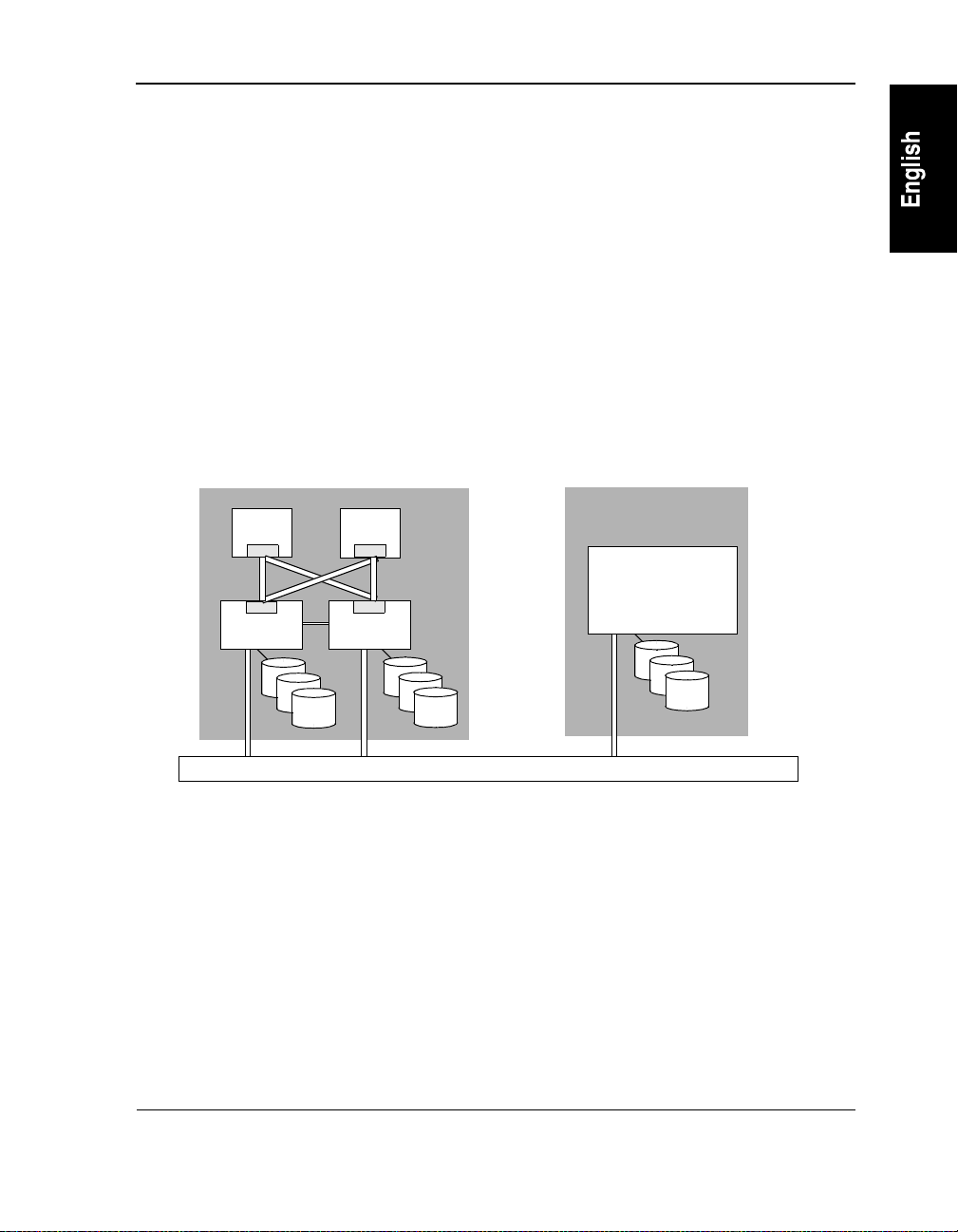
To achieve full redundancy and fault tolerance, the server integrates four industry-standard
Pentium-based systems with HP’s hardware and software. As a result, the Windows NT
operating system and all network services and applications perceive the server as a single
system, as shown in Figure 1-2.
HP NetServer AA Server Physical View
CE
MIC
MIC
IOP IOP
CE
MIC
MIC
Local Area Network
HP NetServer AA Server Logical View
HP NetServer AA
Server
Figure 1-2 HP NetServer AA Server Physical versus Logical View
HP NetServer AA Server Hardware Configuration
With four systems integrated into a single Windows NT fault tolerant server, as shown in
Figure 1-1, the server provides complete hardware redundancy. Because the server uses
redundant hardware, its hardware availability far surpasses that of a standard Windows NT
server. Using redundant hardware also allows online service and replacement of h ardware. The
server supports multiple network connections to provide additional network redundancy and
network traffic control.
7
Page 24

Chapter 1 Introduction
Each system in the server (Figure 1-2) performs specific tasks, functioning as either a CE or
IOP:
• CE (Compute Element) contains the server CPU (s) and memory that supports the
Windows NT operating system and applications. Because there are two CEs, the CEs
provide the redundant CPU (s) and memory for the server.
• IOPs (I/O Pr ocessors) contain the keyboard and mouse, mirrored SCSI devices,
redundant network adapters, and other I/O devices. Because there are two IOPs, the
mirrored SCSI devices (one on each IOP) provide fault tolerant data storage, and the
redundant network adapters (one on each IOP) provide redundant network connectivity.
The IOPs handle all server I/O requests.
The server uses MICs and the ILs to interconnect four standard systems into the server
configuration. This enables these systems to function as one server:
• MIC (Marathon Interface Card) is an adapter that provides a high speed interconnect path
for the server. There are four MICs in a server: one in each IOP, and one in each CE.
• IL (IOP Link) cable connects IOP1 and IOP2.
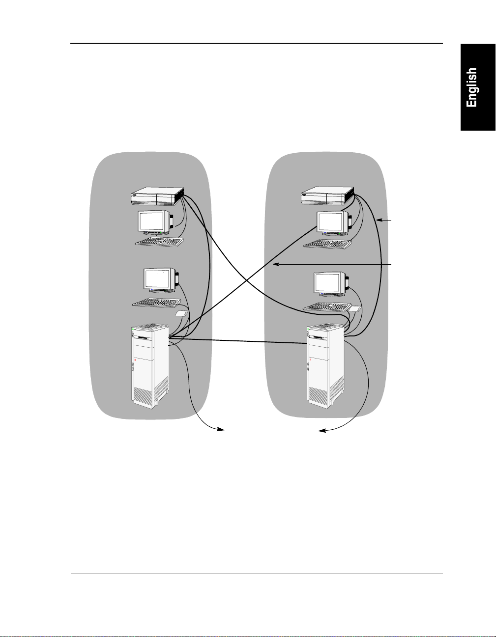
By using redundant hardw are, HP is also able to implement SplitS ite technology in your server.
SplitSite enables you to locate each tuple of a server residing in different locations. This
provides a method of offsite data protection while also providing protection from potential site
disasters.
8
Page 25

Chapter 1 Introduction
Endurance Software
Endurance software integrates and synchronizes processing across four industry-standard
Pentium class systems. All components are capab le of multiprocessing, forming a log ical, fully
redundant, fault tolerant server. This results in the Windows NT operating sys tem , all
applications, and the local area network log ically perceiving the integrated systems in the server
as a standard Windows NT server. Endurance server software provides fault tolerant
functionality, including:
• Redundant processing environment. Using redundant CEs and memory, the software
performs CPU and memory functions in a tightly coupled manner. In the event of a CPU
or memory failure, the operating system remains continuously available, providing
constant computing without any loss of context.
• Redundant I/O subsystem. The software redirects I/O requests from the CE to the IOPs.
The software coordinates all I/O requests, as follows:
- Because all I/O devices in the server physically reside on the IOPs, Software
redirects all I/O requests from the CEs to the IOPs. As a result, these I/O devices are
logically associated with the CE. For example, the software can redirect a CD-ROM
drive physically located in an IOP so that it is logically assigned to the C E (the CE has
complete control of that CD-ROM drive).
- For mirrored disk devices and redundant Ethernet connections, the software
coordinates all I/O processing so that these redundant components appear as a single
logical device. For example, in a mirrored disk set, the two physical disks (one on
each IOP) appear to the CE operating system and applications as on e logical disk. If a
disk failure occurs, the disk operations can transparently continue operating without
affecting any server applications or clients.
• Automatic fault detection and reporting. The software continuously monitors the server. If
the software detects a fault, the server isolates the fault and deconfigures any affected
components. When a fault occurs, software ensures that the server remains operational by
automatically using the redundant components. The fault detection and reporting process
occurs seamlessly, and in a fully operational server, it maintains complete server
availability. The software reports all events, including general status, state changes, and
faults, to the Windows NT event log or displays them in windows as they occur.
9
Page 26

Chapter 1 Introduction
Software also includes the following:
• Automatic disk mirroring. This ensures that data on mirrored SCSI disks are automatically
maintained, and that data on mirrored disks are accurate and current.
• Redundant network connectivity. The server uses redundant network connections (one on
each IOP). The software detects any ph ysical networ k adapter or co nnectivity failures. If a
failure occurs, the redundant adapter automatically controls the flow of all network traffic.
• Transparent reconfigur at i on. After a faulted component is returned to service, the server
automatically reconfigures any required components. For example, when a failed CE is
returned to service, that CE is automatically resynchronized so that it is identical to the CE
that is already in operation. Likewise, when a failed mirrored d isk is retur ned to service, a
mirror copy automatically occurs so that the data on both mirrored disks is identical.
• Server management. The software includes Endurance Manager, a complete management
tool for your server. Endurance Manager is a standard Windows NT application that
enables you to monitor, configure, and manage the server. You can run Endurance
Manager locally (at an IOP or a CE) or from a remote Windows NT server. For a detailed
description of Endurance Manager and its features, refer to Chapter 4.
10
Page 27

2 HP NetServer AA Overview
This chapter provides an overview of the server, including the boot process and state
information. This chapter assumes that you are familiar with the terminology descr ibed in the
Introduction and the Glossary.
This chapter includes the following sections:
Overview . . . . . . . . . . . . . . . . . . . . . . . . . . . . . . .12
HP NetServer AA Boot Process . . . . . . . . . . . . . . . . . . .17
IOP Multi-Boot Options . . . . . . . . . . . . . . . . . . . . . . .20
HP NetServer AA Component States . . . . . . . . . . . . . . . . .22
Monitoring the HP NetServer AA Server . . . . . . . . . . . . . . .31
HP NetServer AA Messages . . . . . . . . . . . . . . . . . . . . .32
11
Page 28

Chapter 2 HP NetServer AA Overview
Overview
The server is a fully redundant, fault tolerant server that provides continuous computing and
redundant I/O devices for your Windows NT server and its applications.
You can monitor and manage your serv er using Endurance Manager, a GUI-based manag ement
application. Using Endurance Manager, you can:
• View the status of a server and its components. This includes the CEs, IOPs, MICs,
interconnects, and all redirected devices.
• Issue commands to manage the server and its components, including enabling and
disabling components.
• Access statistics about the server, including Ethernet counters.
• Determine the status of the server’s mirrored disks, incl uding t he direction of any pend ing
mirror copies, and if a mirror copy is in progress, the percentage of completion.
• Access the Endurance Configuration Utility and Windows NT administration tools.
• View certain messages that display as they occur in a window on the GUI. Messages
displayed on the GUI pertain only to the monitoring of the server; messages related to
changes in the state of the server do not display on the GUI.
• Administer your server from a remote workstation using either a local area network
connection or Microsoft’s Remote Access Server (RAS).
Note: You can also install the online manuals on a remote wor kstation.
For detailed information about the Endurance Manager, refer to Chap ter 4.
A fully operational s erver uses four l icensed copies of the Windows NT oper ating system. Refer
to HP NetS erver AA 6200 Solution Relea se Notes (Release 3.0 Service Pack 1) for details about
the versions of Windows NT that are supported by t his release of the software. Th e requirements
for copies of the Windows NT operating system follow.
• Each CE requires a separate licensed copy of the Windows NT operating system. The CE
operating system offers access to redirected I/O devices, including mirrored (redundant)
disks. As a result, you need to use the CE operating system to run all server applications
and to perform all Windows NT administrative tasks.
• Each IOP requires a separate licensed copy of the Windows NT operating system that
should be accessed only to perform maintenance procedures.
12
Page 29
Chapter 2 HP NetServer AA Overview
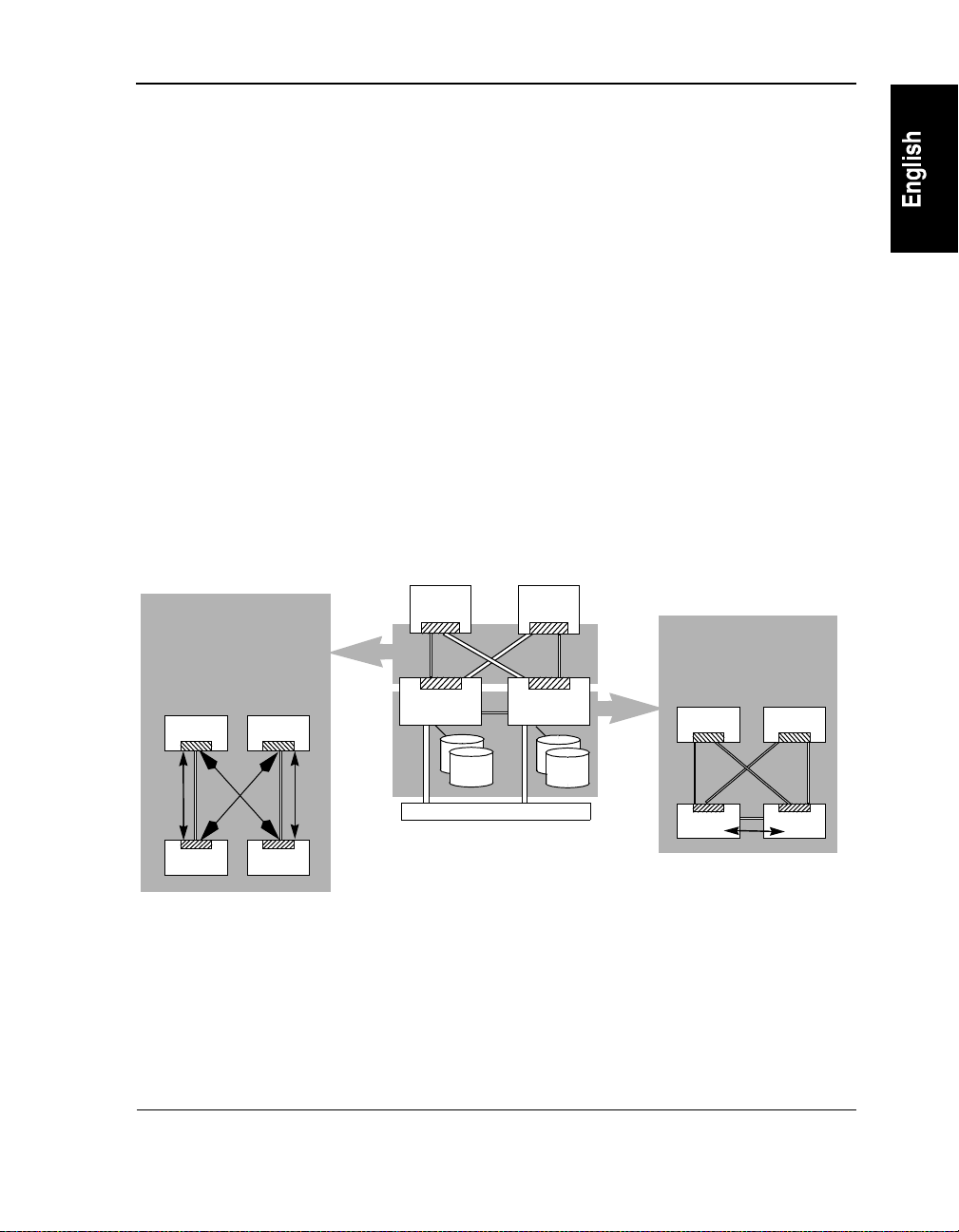
In addition to the concepts described in Chapter 1, the fault tolerant technology coordinates all
I/O requests and responses between the CEs and IOPs using the ESIs and the IL, as shown in
Figure 2-1.
• In the server, the ESIs (Endurance System Interconnects) provide the interconnect paths
for all server I/O requests and responses. These paths connect the IOPs to the CEs as
follows:
- ESI11 is the path from IOP1 to CE1.
- ESI12 is the path from IOP1 to CE2.
- ESI21 is the path from IOP2 to CE1.
- ESI22 is the path from IOP2 to CE2.
• The IL (IOP Link) is a dedicated private network for completing mirror copies
(transferring mirrored disk data) between the IOPs, and for communication between the
IOPs. The IL is physically supported by connecting two Ethernet adapters, one in each
IOP.
The ESI is the I/O data path
between the CE and
redirected devices on the
IOPs.
CE 2CE 1
IOP 1 IOP 2
Figure 2-1 Interconnect Paths in the HP NetServer AA Server
CE 1
IOP 1 IOP 2
Local Area Network
CE 2
The IL is the mirror
copy data path between
the IOPs.
CE 2CE 1
IOP 1
IOP 2
13
Page 30
Chapter 2 HP NetServer AA Overview
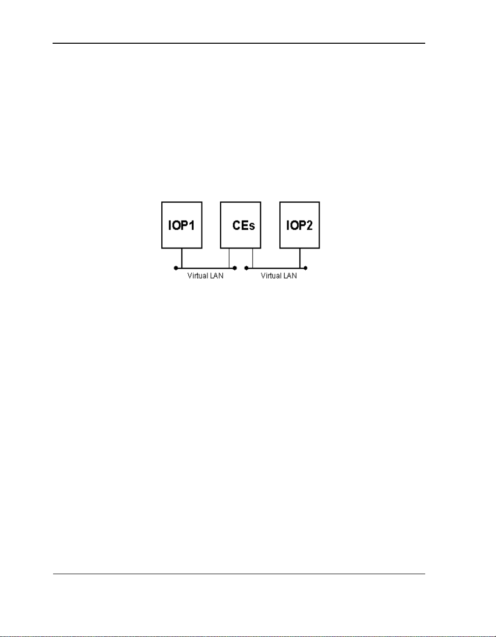
Virtual Network
In addition to the networking described above, the server includes a virtual network that
provides LAN-style connectivity between the CE and each IOP. This connectivity is
independent of any public (redirected) or private (IOP) network adapters.
Within this virtual network, the IOPs and CE appear as three interconnected nodes, as shown in
Figure 2-2.
Figure 2-2 The Virtual Ne twork
Each IOP to CE virtual network is a separate LAN. There is no direct virtual LAN b etween the
two IOPs. (To have this capability , HP recommends th at you install En hanced IL networ king.)
The virtual network requires no additional hardware.
Benefits of the virtual network include:
• IOP access to CE disks while online
• IOP access to redirected floppy drives and CD-ROMs
• CE access to IOP event logs, memory dumps, and other files
The virtual network includes the following components:
• Virtual Net work Redirector (VNR)
• Virtual Netw ork Provider (VNP)
Network transports are bound to VNR and VNP just as they would be bound to any standard
Network Interface Card. Ethernet addresses for all virtual adapters are automatically assigned
and are based on the Ethernet Vendor ID.
14
Page 31

Chapter 2 HP NetServer AA Overview
For information on the installation of the virtual network, see sof twar e ins tallation procedures
in the HP NetSe rver AA Solution Installation Guide.
15
Page 32

Chapter 2 HP NetServer AA Overview
Redirected Video and the CE Desktop Application
In the server, CE video output is redirected to the IOPs. To accomplish this video redirection,
the server uses several kernel mode drivers and the CE Desktop application, which is similar to
industry-standard remote control applications.
The CE Desktop application is a standard Windows NT GUI application. Because its display
window behaves as other st and ard W in do ws NT appl i cati on s, y ou can resi ze and repo si ti on i t,
run it in full-screen mode or in a window, maximize it, minimize it, hide it, and close it. You
can also set various other display preferences.
The CE Desktop appli cation run s on the IO Ps and di splays C E video o utput in a window on the
IOPs. In order to display CE video, you must run the CE Desktop application. However, you
can close the CE Desktop application if you have no need to view CE video and you want to
reduce system overhead.
Refer to Chapter 3 for detailed information about redirected video and the CE Desktop
application.
16
Page 33

Chapter 2 HP NetServer AA Overview
HP NetServer AA Boot Process
When the IOPs and CEs in a server are powered on, they automatically start a boot pr ocess that
results in loading both Windows NT and the software.
When powered on, the IOPs pass power-on self test (POST) and load the Windows NT
operating system and the software. The IOP boot process must complete for the CEs to begin
their boot process. (If the CEs are powered up at the same time as the IOPs, the CEs complete
their POST, and then wait for the IOPs to complete their boot process.)
The CEs do not begin booting until the IOPs are available because all I/O devices (including the
CE boot disk) physically reside on the IOPs. By default, both IOPs must be present for the server
to continue the boot process. This ensures that both CEs use the correct copy of the operating
system and do not run independently. The IOP boot process is summarized in Figure 2-3. A
detailed IOP boot process flowchart is in Appendix B.
IOPx
Powered on and
passes POST
IOPy
Powered on and
passes POST
Windows NT
is loaded.
Endurance software
is loaded.
Windows NT
is loaded.
Endurance software
is loaded.
IOPx and IOPy
communication i s
established.
IOPs join.
CE boot starts.
17
Page 34

Chapter 2 HP NetServer AA Overview
Figure 2-3 Overview of IOP Boot Process
After the IOPs complete their boot process, the CEs boot: one CE loads the Windows NT
operating system; then the other CE is synchronized so that both CEs pe r for m all CPU and
memory functions in a tightly coupled manner. This ensures that in the event of a CPU or
memory failure, the server operating system provides continuous computing without any loss
of context. After the CE boot process completes, the server is available for use. For an IOP to
service the CE boot request, i t must have completed boo t, as shown in Figu re 2-3 and described
in Appendix B.
The CE boot process is summarized in Figure 2-4. A detailed CE boot process flowchart is in
Appendix B.
18
Page 35

Chapter 2 HP NetServer AA Overview
CEx
Powered on and
completes POST
CE issues boot request.
IOP services boot
request.
IOP servicing boot
redirects its keyboard
to the CE.
CE loads Windows
NT and Endurance
software.
CE has active control
of all redirected
devices.
CEy
Powered on and
completes POST
CE issues boot request.
If IOPs are both
present and t heir dis ks
are not current , a
mirror copy starts.
CEs synchronize and
start executing in lock
step.
Figure 2-4 Overview of CE Boot Process
By default, when the server completes the entire boot process, the keyboard and pointer (mouse)
on each IOP control the CE operating system. Use Ctrl-Shift-F12 or a key sequence you define,
or use the CE tray icon to toggle input control between the CEs and local IOP.
Warning: Once the CEs have synchronized, do not physically attach or
remove keyboards or any devices from a CE. Doing so could
cause loss of synchronization in some CE models.
19
Page 36

Chapter 2 HP NetServer AA Overview
HP NetServer AA Characteristics During the CE Boot Process
During the CE boot process, you can use Endurance Manager to view the s tate transitions of the
server components. Server component state transitions are detailed in Table 2-1.
Until the CE boot completes, the only redirected keyboard is the one attached to the IOP that is
serving the boot request. Durin g CE boot, if you m ust access the CE using a redirected keyboard
(for example, to select a multi-boot option), use the keyboard on the IOP that is servicing the
boot request. (If you do not know which IOP is servicing the boot request, use Endurance
Manager on either IOP to see which keyboard is redirected. Then, use that keyboard.)
If a non-mirrored SCSI device or both member s of a mirror set are not present (cannot be located
for any reason) when the CE operating system boo ts, that device remains unavailable to the CE
operating system. Later, if the device becomes available, you must reboot the CE operating
system for the device to be accessible from the CE operating system.
Similarly, if both adapters for a redirected network device are unavailable to the CE operating
system during boot, the device remains unavailable to the CE operating system. Later, if the
device becomes available, you must reboot the CE operating system for the device to be
accessible from the CE operating system.
IOP Multi-Boot Options
During the IOP boot p rocess, the I OP multi-boot op tions for the W indows NT oper ating system
are displayed on the boot loader menu. These options allow you to choo se the system ro ot that
you want to use.
Note: Do not boot your IOP in any mode other than Operational Endurance I/O
Processor Mode without explicit instructions from your ser vice provider or
without following the information described in the documentation.
By default, the installed multi-boot options for an IOP are descr ibed in Table 2-1.
20
Page 37

Chapter 2 HP NetServer AA Overview
Table 2-1 Multi-Boot Options for IOPs
Multi-Boot Option Description
Operational Endurance I/
O Processor Mode
Offline Endurance I/O
Processor Mode
IOP Maintenance Mode This option is for emergencies only. This option boots a copy of the original
This option is the normal operating mode for the IOP . This option boots a copy of
Windows NT that contains and activates Windows NT and software .
This is the only mode that allows an IOP to join the server.
This option is for performing maintenance, such as upgrading the system
configuration or system software. This option boots Windows NT and some
software services. As a result, redirected SCSI devices are available locally (at the
IOP), and the IOP is not active in the server configuration. Both IOPs must be
active for the server to be fully fault tolerant.
Note: Network adapt ers, floppy drives, and serial port s tha t are redirected are not
accessible when booting in Offline HP NetServer AA I/O Processor Mode. To
transfer files (for example, con fig uration files) between IOPs, do one of the
following:
- Using the virtual netwo rk, pla c e th e fi le on a CE disk. This method is
available only if the CE operating system is running and both IOPs
are active.
- Install Enhanced IL Net working.
- Reboot into Endurance Maintenance Mode.
Windows NT that you installed (before any softwa re was installed).
21
Page 38

Chapter 2 HP NetServer AA Overview
HP NetServer AA Component States
The server components can report any of the following states, depending on their status:
• Server States
• CE Operating System States
• CE States
• IOP States
• Interconnect States
• MIC Port State Display Lights
• Mirrored Disk States
• Network Connection States
• Keyboard/Pointer States
• Other HP NetServer AA Component States
Note: You can use the Endurance Manager to view the current state of any component
in the server.
Server States
The server states are:
Table 2-2 Server States
State Description
Offline Indicates that non e of the IOPs or CEs in the serve r ar e active.
Online Indicates that one IOP or CE is ready, but none are active.
Active Indicates that at le ast one CE or IOP is active.
22
Page 39

Chapter 2 HP NetServer AA Overview
CE Operating System States
The CE operating system states are:
Table 2-3 CE Operating System States
State Description
Offline Indicates that the Windows NT operating system is neither running nor
Booting Indicates that the Windows NT operating system is in the process of being
Active Indicates that the Windows NT operating system is running on at least one
booting on any CE.
booted on a CE.
CE.
CE States
The CE states are:
Table 2-4 CE States
State Description
Offline Indicates that the CE is not available for use in the server. The CE is
Ready Indicates that the CE is powered up and ha s est ab li s hed communications
Booting Indicates that the CE(s) are in the proc e ss of booting the Windows NT
typically in this state when it is powered down or if it cannot communicate
with an IOP because the ESI between the CE and IOP is not usable.
with an IOP. After this state, the CE transitions to either Booting or Sync-
Slave (where CE sync hronization is performed).
operating system from the IOP(s). This process typically takes a few
minutes, at which point the CE transitions to active.
Active Indicates that the CE is actively executing the Windows NT operating
system. The CE remains in this state until it is shutdown, fails, or is
removed from the configu ration as a result of an Endurance Mana ge r
command.
23
Page 40

Chapter 2 HP NetServer AA Overview
Table 2-4 CE States
State Description
Faulted Indicates that the server removed the CE from operation as a result of one
Disabled Indicates that you issued an Endurance Manager CE Disable command
Sync-Slave Indicates the CE that is being activated by the server while the other CE is
Sync-Master Indicates the CE that is running the Windows NT operating system while
or more faults that were attributed to the CE. Th e CE remains in this state
until it is repaired and an E ndurance Manager CE Ena ble command is
issued.
that removed the CE from ope ration. The CE remains in this state until it
is enabled using an Endurance Manager CE Enable com m and.
already running the Windows NT opera ting system.
the server is activating the othe r CE .
IOP States
The IOP states are:
Table 2-5 IOP States
State Description
Offline Indicates that the IOP is not available for use in the server. The IOP is typically in this state if
it is powered down or if it cannot communicate with other IOPs because the Interconnects
between the IOP a nd the server are not usable.
Ready Indicates that the IOP is ready to become an active member of the server configuration. The
Initializing Indicates that the IOP is in the proce ss of agreeing on the states of all server components and
Initialized Indicates the transit ional state an IOP enters a t the compl etion of th e IOP init ializat ion pro cess
Joining Indicates that the IOP is in the process of being joined into the active server configuration.
IOP remains in this state until it joins w ith another I O P, or until it boots the CE. Then, the
IOP transitions to active.
parameters with the second IOP. As this process completes, the IOP transitions to active or
joining.
just before it begins joining with the second IOP. Then, the IOP transitions to the joining
state.
During this process, all providers perform initialization wit h the ir pee rs on th e remote IOP,
and the IOP is activated into the server. Then, the IOP transitions to active.
24
Page 41

Chapter 2 HP NetServer AA Overview
Table 2-5 IOP States (Continued)
State Description
Active Indicates that the IOP is a fully active member of the server configuration. In this state, the
Faulted Indicates that the server removed the IOP from operation as a result of one or more faults that
Disabled Indicates that you issued an Endura nc e Manager IOP Disable command to re mo ve the IO P
Shutdown Indicates that the IOP is being shut down either because you issu ed an Endurance Manager
IOP serves I/O requests from any active CE (s) a nd pa rti c ipates fully in all fault handling
events. The IOP remains in this state until it is shutdown, disabled, or removed from the
configuration as the result of a system failu re .
were attributed to the IOP. The IOP remains in this state until it is repaired and an Endurance
Manager IOP Enable command is issued.
from operation. The IOP remains in this state until it is enabled using an End ura nce Manager
IOP Enable command.
IOP Shutdown command, or because a fault occurred that requires the server to remove the
IOP from the configuration. The IOP remains in this state only as long as it takes to properly
shut down the Windows NT operating system on the IOP.
Interconnect States
There are two types of Interconnects: an IL (IOP link) that connects one IOP to the other IOP,
and an ESI (HP NetServer AA System Interconnect) that connects an IOP to the CE.
The IL cables pro vide a path for communicating system states and status information. This path
also provides the mirror copy data path.
The Interconnect states are:
Table 2-6 Interconnect States
State Description
Offline Indicates that the Intercon nect is not in use by the server, but is available fo r u se. The
Interconnect typica lly transitions to ready from this state.
Ready Indicates that the Interconnect was activated by an IOP and is waiting for the component (CE
or IOP) at the other end of the interconnect to also activate the Interconnect. Then, it
transitions to online.
Online Indicates that the Interconnect is in use and communication can be performed between the
server compo nents conne cted by it. The In terconnect remains in this s tate until the server
activates the remote component. Then, the Interconnect transitions to active.
25
Page 42

Chapter 2 HP NetServer AA Overview
Table 2-6 Interconnect States
State Description
Active Indicates that the server components on both sides of the Interconnect are active members of
Faulted Indic at es th at the server removed the Interconnect from operation as a result of one or more
the server con figuration . Th e Interconn ect remains in t h is state until on e of the compon ents
is removed from the confi guration. Then, the Interc onnect transitions to offline or ready.
faults that were att ributed to the Int erconnect . The In terconnec t remain s in this state until it is
repaired and then enabled (using Endurance Man ag er).
MIC Port State Display Lights
Each IOP collects and displays the status of its local MIC p orts alon g with the st atus of the CE
MIC ports connected through the cable. CE status is relayed to the IOP with the assistance of
MIC firmware; therefore, the CE port status is only available after the CE MIC BIOS has set
its ports to a software-enabled state.
The following table explai ns the MIC port stat e lights displayed on the MIC’s graphical display
in the Endurance Manager window.
Table 2-7 MIC Port State Display Lights
Color State Description
Green Good The MIC hardware is successfully sending and receiving fiber
signals through the fiber connecto r.
Red Failed The MIC port has detecte d a break in communication ove r the
path, which may be caused by a cable disconnection or a failure
in the transmitters or re ceivers associated with this path. This
light does not indicate which end of the path may have failed,
and does not imply that the MIC reporting this state is broken.
Lost Power The MIC port at the opposite end of the cable has detect ed a
Orange
PCI Reset T he MIC port at the opposite end of the cab le has de te ct e d a
local DC-low conditio n ( p ower loss).
PCI bus rese t.
26
Page 43

Chapter 2 HP NetServer AA Overview
Table 2-7 MIC Port State Display Lights
Color State Description
Gray Unknown/
Unavailable
Black Uninitialized The MIC hardware has not sensed any fiber signals through the
This state occurs only on CE MIC ports. It indicates that, from
the IOP’s perspective, no information about the state of this port
has been received. Normally th e CE MIC firmware relays the
local port status to the IOP MICs. This does not occur, however,
until the CE MICs are powered on and able to establish
communication.
fiber connector since the IOP or CE has booted.
Mirrored Disk States
The mirrored disk states are:
Table 2-8 Mirrored Disk States
State Description
Online Indicates that a disk is available for use or is currently in use by the CE operating system.
As a mirror copy begins, a mirror copy target transitions from offline to online and remains online
when the mirror copy completes successfully. However, if the copy cannot complete successfully
because of some system-wide state change or because of a disk level state change, the disk state
transitions to offline or faulted.
Offline Ind icates that a disk is not available for use by the CE operating syst em. A di s k can be offline
because either:
• The disk is the target of a mirror copy that i s pending (not started).
• The disk was not detected during system boot. Possible reasons include the disk was powered
off, failed, or was improperly defined using t he Endurance Configuration Util i ty.
• The disk was detected during system boot, but a characteristic of the disk was invalid. Possible
reasons include: a corrup t or in va li d pa rti ti on t ab le , a corru pt or invalid partition, or the disk
was the target of a mirror cop y that previously failed to c o mplete.
• The mirror copy targe t is to o small for a gi ven mirror copy source. In this case, th e tar g et disk
remains offline indefinitely and must be replace d by a larger disk.
27
Page 44

Chapter 2 HP NetServer AA Overview
Table 2-8 Mirrored Disk States (Continued)
State Description
Faulted Indicates a disk failed a read or write request after repeated retries. The disk is not available for
Disabled An administrator may disable a mirrored disk at any time. The mirrored disk remains disabled
use by the CE operating system.
Y ou can use Endurance Manager to re-enable a disk that has experienced unrecovered failures and
return it to service. Yo u do not need to reboot the IOP to bring the disk back online. An ensuing
mirror copy to the disk may correct ba d spot s pre sent on the failed disk. However, if the disk has
completely or substant ially failed , it will continue to rever t to the faulted state. In this cas e, you
should replace the disk.
A disk is also regarded as faulted if it failed during previous operation of its IOP. For example, if
a disk experienced rea d or write errors and was d eemed to be faulted, then the faulted state would
remain across IOP reboots, even if you replaced the failed disk. In this case, you must explicitly
enable the disk to clear its faulted condition.
until it is explicitly enabled. It is possible to delay or halt a mirror copy by disabling the target of
the copy.
Warning: Do not disable the source of a mirror copy or all usable (online) disks in a mirror
set, because this would make the entire mirror set inaccessible.
If all members of a mirror set are inaccessible during CE boot time, Windows NT
does not recognize the mirror set even if the disk s are later ret u rn ed to an online
state. In this case, a full reboot of the CE is required to enable Windows NT to
recognize the mirror se t.
Mirrored Disks in the Server
Because disk remirroring ensures availability of data on the server, the dis ks in the server have
these characteristics:
• The target disk of a mirror copy cannot fully service CE requests until its mirror copy
completes.
• If the source disk of that mirror set becomes unavailable for any reason before the mirror
copy completes, the CEs no longer have access to that mirror set.
• If the CEs cannot access the CEs’ boot disks, the CEs reset.
If a mirrored disk fails, use Endurance Manager to attempt to enable that disk. If enabling the
disk succeeds, a mirror copy is automatically queued.
28
Page 45

Chapter 2 HP NetServer AA Overview
Network Connection States
The network connection states are:
Table 2-9 Network Connection States
State Description
Online Indicates that the Ethernet adapter and its associated network connection
Offline Indicates that the software de te ct ed a loss of network connectivity on the
Initializing Indicates that the adapter is in an intermediate state from which the
Faulted The adapt er or its co nne ction to the network has failed. Possible reasons
Disabled Indicates that the adap te r w as disabled using Endurance M anager.
is active in the server configuration. The Endurance Manager
Administration Window (Chapter 4) uses color to indicate whether the
adapter is either primary or standby.
• Primary indicates that the ad apter is respo nsible for all transmits and
receives.
• Standby indicates that the adapter is not responsible for transmits or
receives, but is active ly rec ei ving and monitoring the netw ork. If the
primary connection fails, this adapter and its connection immediately
assume primary status without loss of network traffic or cli ent
connectivity.
adapter.
adapter will transition to standby or primary.
include:
• Adapter configuration error
• Excessive network errors
29
Page 46

Chapter 2 HP NetServer AA Overview
Keyboard/Pointer States
The keyboard and pointer states are:
Table 2-10 Keyboard/Pointer States
State Description
Online Both the keyboard and pointer are available to the server.
Faulted The keyboard or pointer is not available to the entire server configuration.
In some cases (for example, fai le d ke yboard or pointer), the input device
is not available to either the IOP or CE. In other cases (when the keyboard
or pointer are not identical), the keyboard or pointer is unavaila ble to the
CE, but remains availab le lo cally (at the IOP).
Other HP NetServer AA Component States
The CD-ROM, floppy disk drive, serial port, and tape drive states for the server are:
Table 2-11 States of Other HP NetServer AA Components
State Description
Online Indicates that a device is availabl e f or use by the CE operating system.
Offline Indicates that a devic e is not available for use by the CE opera ti ng syst em, but the device is not
necessarily failed. Possible reasons for offline include:
• For some devices, a transitional state that precedes online.
• The device was disabled using End ura nc e Manager.
• The device was not detected by software. Possible reasons include the device was powered
off, or was improperly defined using the Endurance Configuration Utility.
Additionally , some devices may be set to offline to temporarily block their access until the
device’s state can be pr operly identified.
Faulted Indicates a device failure has been detected. If the error is transient, you can return the device to
service by enabling the device (using Endurance Manager), and rebooting the IOP . If the error is
not transient, you need to replace the device.
30
Page 47

Chapter 2 HP NetServer AA Overview
Monitoring the HP NetServer AA Server
Because the server is fault tolerant, when a fault occurs (for example, a failed disk), the server
continues operating. However, even though it is operating, it may be vulnerable. This means
that any failure to the faulted compon ent ’s redundant counterpart affects the availability of the
server. Because of this, you need to monitor the status of the components in your server and
correct any faults. You can monitor t he server using any or all metho ds describ ed in Table 2-1 2.
Table 2-12 Monitoring Tools for the HP NetServer AA Server
Monitoring Tool Description Refer to ...
Endurance Manager Provides complete server management. Using Endu rance
Windows NT Event
Viewer
MTCLOG Utility Displays th ose events that are logged to the Windows NT
Manager, you can:
• View current status for the components of your serv er.
• Display the current mirror cop y status of your mirrored
disks.
• Execute commands to mana ge and display information
about your server and its components.
Displays all events reported to the Windows NT operating
system, including events. Use this log when monitoring your
server or diagnosing potential faults.
Event Viewer as they are being logged. The MTCLOG Utility
is an MS-DOS application that displays onl y messages by
filtering the logged messages being written to the Windows
NT Event Log.
Chapter 4 for
Endurance Manager
information
HP NetServer AA
Solution Messages for
message information
Chapter 7 for
MTCLOG
information
HP NetServer AA
Solution Messages for
message information
31
Page 48

Chapter 2 HP NetServer AA Overview
HP NetServer AA Messages
When it is operational, software continuously monitors the server. It reports status and error
messages by logging most messages in the Windows NT event log. Software displays some
messages as they occur, either directly on the Windows NT blue screens during the text phase
of boot or when a CE is being deconfigu red; in p op-up wi ndows ; and for mes sages th at pertai n
to the monitoring of the server, in a window on the Endurance Manager GUI. You can view
logged messages using:
• Windows NT Event Viewer that displays all messages reported to the Windows NT
operating system, including those messages that are logged.
• MTCLOG, an event log utility, that displays logged messages as they are being logged.
Those messages that are logged in the Windows NT event log are logged as follows:
• Each IOP’s Windows NT System Event log contains the mes sag es that were g enerated by
that IOP. For example, IOP1 contains any messages generated by IOP1.
• The CE’s Windows NT System Event log contains both CE messages and the messages
that are logged by each IOP. The IOP messages are logged to the CE’s Event Viewer as
follows:
- If a CE is not active (for example, has not completely booted), the IOP messages are
stored in a buffer on the IOP and sent to the CE when it becomes available. An IOP
can accurately buffer up to 75 messages.
- When any CE becomes active, the CE uploads the messages from the IOP event
buffers, and logs those messages into the CE’s Event log.
Because of this process, in the CE Even t Viewer, the timestamp inf ormation for messages
originating in the IOPs is the time that the CE received the message; it does not necessarily
indicate the time that the message occurred on the IOP. To confirm the time that the
message occurred, check the event logs on the IOPs.
Note: If diagnosing events that occurred while the CE oper ating s ystem was o ut of
service, it is best to copy and then merge the IOP event logs. The resulting file
indicates the proper timestamp information and reflects the order in which the
messages actually occurred.
In the CE Event Viewer, the message
completed for CE1 indicates the CE started uploading any IOP messages. Any
IOPn.MtcMon status: The boot process has
subsequent messages were received from the IOPs without delay.
32
Page 49

Chapter 2 HP NetServer AA Overview
Messages logged to the Windows NT System Event log use the standard Windows NT event
format. (Refer to Windows NT documentation for the detailed information on Event Viewer
fields and descriptions.) Messages are reported using the following icons and severity levels,
described in Table 2-13.
Table 2-13 Event Log Icons and Message Severity Levels
Severity Level Description
Informational
Warning
Error
Informational messages are the least severe and do not require action.
Examples of informational messages include:
• Reporting benign state changes
• Reporting commands as they are issue d
• Reporting completion st atus of user-initiat ed processes
Warning messages may require attention. A continued series of warning
messages merits review to s ee if corrective action is required.
Examples of warning messages i nclude:
• Potential resource allocation issues
• Issuing invalid commands
Error messages are the most severe and require immediate attention. In
some cases an error message reports a serious state change or transition
that may have resulted in the server being in a vulnerable state or possibly
out of service.
Examples of error messages inc lude:
• Serious hardware and software failure s, such a s unavailable disks
• Power supply failures
• Windows NT operating system failures
• Server interconnect pa th fail ure s
When troubleshooting a server, check the event logs for messages that start with or .
Because the server uses standard message reporting, you can integrate standard notification
applications (for example, paging devices and third-party software) to notify you when a fault
occurs.
For a detailed listing of messages, refer to the manual HP NetServer AA Solution Messages.
33
Page 50

Page 51

3
This chapter describes redirected video and the CE Desktop application, a Windows NT
application that runs on the server IOPs and displays the CE video output on the IOPs. This
chapter assumes that you are familiar with the terminology described in Chapter 1 and the
Glossary.
This chapter includes the following sections:
Redirected Video and the CE Desktop Application
Overview . . . . . . . . . . . . . . . . . . . . . . . . . . . . . . .36
CE Video During Boot . . . . . . . . . . . . . . . . . . . . . . . .37
Redirected Video Components . . . . . . . . . . . . . . . . . . . .38
Video Recommendations . . . . . . . . . . . . . . . . . . . . . . .40
Using the CE Desktop Application . . . . . . . . . . . . . . . . . .41
35
Page 52

Chapter 3 Redirected Video and the CE Desktop Application
Overview
In the server, CE video output is redirected for display on the IOPs. To accomplish this
redirection, the server uses several ker nel mode dr ivers and the C E Desktop application, whose
user interface is similar to industry-standard remote control applications.
The CE Desktop application is a standard Windows NT GUI application. It runs on the IOPs
and displays CE video outp ut in a wind ow on the IOPs. To di spla y CE video , you must run the
CE Desktop application. Ho wever, wh enever yo u do not need to view CE v ideo, you can clos e
the application, which is a useful way to reduce system overhead.
After the text phase of the Wi ndows NT boot proces s, t he softwa re disabl es the CE v ideo card.
The Video Display Driver (MtcVidD) and Video Miniport Driver (MtcVidR) redirect the CE
video output to the IOPs. These drivers are required; you can not substit ute other video drivers.
Also, you cannot run any r emote contro l applications that replace the video drivers o n the C Es.
Because the CE Desktop application is a standard Windows NT application, the display window
behaves as other windows in Wi ndows NT appl ications. You can resize and repos ition it, run it
in full-screen mode, maximize it, minimize it, hide it, and close it. You can also select various
other preferences of display. Refer to Video Recommendatio ns on page 40 for informat ion about
customizing your display with regards to the most efficient use of the CE Desktop application.
The following sections describe Redirected Video in detail.
36
Page 53

Chapter 3 Redirected Video and the CE Desktop Application
CE Video During Boot
The CE Desktop applicatio n displays ou tput from the CE that occurs after the CE passes POST
and the text phase of the Windows NT boot process. During the boot process, the following
information is displayed on a monitor connected to the CE video adapter — before the video
drivers are loaded:
• POST messages
• The OS Loader screen with the Windows NT boot selection menu
• Text phase of the Windows NT boot pro cess (blu e screen durin g boot of t he Window s NT
operating system)
Once a server is fully operational, monitors are not used by the CEs. If the CE Desktop
application is not runn ing, using the hot key sequence to switch input focus to t he CE is ignored.
For information about running the CE Desktop application, see Running the CE Desktop
Application on page 42.
The input and output of certain tasks that you perform on the CE are displayed using the CE
video adapters and require that a monitor be con nected to the CE. Thes e tasks are all MS-DOSrelated func t ions and tests, including:
• Running BIOS setup, test, and diagnostics
• Flashing the HP Interface Cards (MICs) during an upgrade or installation of a hotfix
• Viewing POST messages and the text phase of Windows NT boot
To perform these functions and view this output, do one of the following:
• Install and use a Keyboard/Video/Mouse (KVM) s witch so that IOP monitors can be used
as CE monitors.
Note: Refer to Appendix A in the HP NetServer AA Solution Installation Guide for
detailed information about installing, cabling, and using a KVM switch.
• Temporarily attach a monitor to the CE and perform and view the tests on the monitor
attached to the CE.
37
Page 54

Chapter 3 Redirected Video and the CE Desktop Application
Redirected Video Components
This section describes the redirected video components used in the server. The kernel mode
components of redirected video include software that runs on the IOP and on the CE.
Software Running on the IOPs
• MtcVidP.sys — the Video Provider
• MtcVideo.exe — the CE Desktop application
The Video Provider on each IOP communicates with the Video Redirector. It receives
information from the Video Redirector that is used for displaying the CE video on both IOPs.
If one CE stops functioning, CE Deskto p wind ows can be disp la yed on both IO P, due to the
redundancy in the system.
Software Running on the CEs
• MtcVidR.sys — the Video Miniport Driver and Redirector
• MtcVidD.sys — the Video Display Driver
• MtcCEtray.exe — the CE tray icon executable
The Video Redir ector co mmunicates with the Video Provi der and is responsible for redirect ing
the video display from the CE to the IOPs.
CE Video Drivers
When the Video Redirector and Display Driver are loaded, they disable the CE video adapter.
You cannot disable the video drivers or substitute other drivers.
CE and IOP Video Modes
It is not necessary to have the display resolution of the CE Desktop area and that of the IOP
desktop area match each other.
Not only can the video displays of the CE desktop and IOP desktop be different from each other,
but you can run the two IOP video displays in different modes.
38
Page 55

Chapter 3 Redirected Video and the CE Desktop Application
In the IOPs, you sho uld use any vi deo cards t hat supp ort r esol utions of at l east 1 024 X 76 8 and
also support more than 256 colors. The C E color palette is always set to 256 colors. You s hould
run the IOPs at least one setting above 256 colors. Otherwise, the CE Desktop application will
not display colors properly.
Booting in Base Video Mode
If a server experiences system problems, it is possible to boot the CE in base video mode, which
uses standard Windows NT VGA video drivers. This enables you to bring up the CE in order to
determine and diagnose system problems. However, it is not possible to synchronize a second
CE in this mode. The use of the standard video driver in base video mode prevents CEs from
synchronizing.
Note: It is likely that you will never need to boot the CE in base video mode, and in fact,
you should not do so unless your service provider explicitly recommends this as a
way of diagnosing and correcting a possible problem.
39
Page 56

Chapter 3 Redirected Video and the CE Desktop Application
Video Recommendations
The following sections provide recommendations for the most efficient us e of system resources.
Some Remote Control Applications Not Supported on the CE
The server does not support the use of remote control applications on the CEs that replace the
video drivers with their own drivers. The video drivers are required for CE synchronization.
Recommendations for Efficient Use of Redirected Video
Table 3-1 lists recommendations for reducing the overhead of redirected video. In most cases,
it is best to avoid applications that cause frequent video updates because those updates could
impose additional load on the server and could have a negative impact on system performance.
Table 3-1 Recommendations for Efficient Use of CE Video
About . . . Recommendations
3-D applications Avoid running 3-D applications or complex screen savers, such
as those that render 3-D images, on the CE.
Cursors, screen savers, and wall
paper
Animated applications Avoid running animated applications.
Different background display on t he
CEs and IOPs
Avoid animate d cu rsors and screen savers in the server.
Use only monochrome cu rsors. Color cursors are not
supported. The redirected video software substitutes a
monochrome cursor whenever a request is received to set a
color cursor. As a result, so m e drag-and-drop operations on a
server look different than those operations on ot he r syste ms.
Avoid using the same background display on the CE deskto p
and the IOP desktop. If you do not do so, when you run the CE
Desktop applicatio n in fu ll -screen mode, it can be difficult to
determine whether you are viewing the CE desktop or the IOP
desktop display. Refer to page 42 for more information about
running the CE Desktop application in full-scre e n mode.
40
Page 57

Chapter 3 Redirected Video and the CE Desktop Application
Using the CE Desktop Application
This section describes how to launch and use the CE Desktop application.
Before you launch the CE Desktop application, set the color palette for the IOPs to a minimum
of one setting above 256 colors. To set the number of colors:
1. From the Task Bar, select Start Settings Control Panel Display.
2. Select the Settings tab.
3. In the Color Palette box, select the number of colors from the list box.
After you launch th e CE Desktop ap plication, yo u can change the CE display s ettings to su it the
needs of your site.
Launching the Application
You can launch the CE Desktop application in several ways:
• From the Endurance program group
Select Start
Programs Endurance Endurance CE Desktop to launch the
application.
• From the Endurance Manager application
Select Tools
CE Desktop.
• Automatically when you log in
Add the CE Desktop application to the Start-up group on the IOP(s).
• From the desktop
Create a desktop shortcut icon for quick access to the program.
The CE Desktop application starts and displays the CE Desktop window on the IOP.
41
Page 58

Chapter 3 Redirected Video and the CE Desktop Application
Running the CE Desktop Application
The first time that you access the application, it runs in a window. After that, you can run the
CE Desktop application either in a window or in full-screen mode.
Table 3-2 Video Mode Options
In a window, the application: or In Full-Screen Mode, the application:
Runs in a window with the IOP desktop
visible
Enables you to see CE and IOP
applications simultaneously
Runs with scroll bars and autoscrolling
Autoscrolling scrolls the window in
the direction of the mouse when you
move the mouse to any of the
window’s borders.
Restricts the movement of the mouse
within the perimeter of the CE Desktop
when input focus is directed to the CEs
Takes over the entire display and hides the IOP desktop
Enables you to see the entire CE desktop
Runs without scroll bars
To run the application in full screen mode:
1. Double click the CE Desktop icon on the title bar.
2. Check Full Screen Mode.
Full-screen mode is available only when the CE and IOP are running at the same video
resolution. To determine the video resolution in which the CE and IOP are running:
1. From the Task Bar, select Start Settings Control Panel Display.
2. Select the Settings tab.
3. Note the resolution on both the CE and IOP.
4. If necessar y, change the re solution by moving the s lider on the Desktop Area so that both
CE and IOP run at the same resolution.
42
Page 59

Chapter 3 Redirected Video and the CE Desktop Application
When the application is running in full-screen mode and you want to run the application in a
window:
1. Change the input focus to the IOP. See Changing Input Focus on page 43.
2. Click the CE Desktop icon on the title bar.
3. Uncheck the Full Screen Mode option.
If the CE is running at a lower resolution than the IOP, then the entire CE desktop can be resized
so that it is visible without scroll bars. If the CE is running at a higher resolution than the IOP,
the CE Desktop application runs in a window and displays with scroll bars.
Changing Input Focus
When input focus is directed to the CEs, the mouse is restricted to the CE Desktop window. To
shift the input focus to the IOP, perform one of the following actions:
• Press the hot key sequence Ctrl/Shift/F12 or the sequence you assigned if you have over-
ridden this default sequence.
• Right-click the CE tray icon.
From the menu, choose the IOP of the tuple that you are using.
The input focus then shifts to the IOP, and the CE desktop changes to a window if it was running
in full-screen mode.
When input focus is directed to the IOPs and you click anywhere within the CE desktop
window:
• Input focus switches to the CEs.
• In full screen mode, the application takes over the entire desktop.
• In a window, the mouse is restricted to the CE desktop window.
Setting Video Resolution and Refresh Frequency
The CE desktop default resolution is 640 x 480 pixels. You can change this setting using the
Display application in the Control Panel window. If necessary, change the resolution in the
Desktop Area on the Settings page. The lower you set the resolution, the less system resources
redirected video uses.
43
Page 60

Chapter 3 Redirected Video and the CE Desktop Application
The CE video drivers support the following resolutions:
• 640 by 480 pixels, 256 Colors
• 800 by 600 pixels, 256 Colors
• 1024 by 768 pixels, 256 Colors
By default, the Refresh Frequency setting is Use hardware default setting. You can change
this setting to minimize screen updates and conserve system resources. Select an appropriate
frequency setting i n the Refres h Frequency area on the Se ttings p age of the D isplay app lication.
Each resolution supports the following refresh frequencies:
• Hardware default refresh (100 Hertz)
• 40 Hertz (4 times per second updates)
• 60 Hertz (6 times per second updates)
• 80 Hertz (8 times per second updates)
• 100 Hertz (10 times per second updates)
• 200 Hertz (20 times per second updates)
The refresh frequency controls th e maximum number of v ideo updates that are s ent to the IOPs
each second.
44
Page 61

4 Endurance Manager
This chapter describes the Endurance Manager, the server management application. This
chapter assumes that you are familiar with the terminology described in Chapter 1 and the
Glossary.
This chapter includes the following sections:
Overview . . . . . . . . . . . . . . . . . . . . . . . . . . . . . . .46
Starting the Endurance Manager . . . . . . . . . . . . . . . . . . .47
Endurance Manager Window . . . . . . . . . . . . . . . . . . . . .48
Display and Control Window . . . . . . . . . . . . . . . . . . . . .61
Options Window . . . . . . . . . . . . . . . . . . . . . . . . . . .64
Menu Options . . . . . . . . . . . . . . . . . . . . . . . . . . . . .66
Using Endurance Manager on a Remote Workstation . . . . . . . .70
45
Page 62

Chapter 4 Endurance Manager
Overview
The Endurance Manager is a complete management tool for your server. Endurance Manager is
a standard Windows NT application that enables you to:
• View the status of any server and its components. This includes the server, and CEs,
IOPs, interconnects, keyboards, pointers, redirected devices, and Ethernet connections.
• Issue commands to manage the server and its components, including enabling and
disabling server compon ents.
• Access statistics about the servers, including Ethernet counters.
• Determine the status of the servers’ mirrored disks, incl uding t he direction of any pend ing
mirror copies and, if a mirror copy is in progress, the percentage of completion.
• Access the Endurance Configuration Utility and Windows NT administration tools.
• Administer your servers from a remote workstation, using either a local area network
connection or Microsoft’s Remote Access Server (RAS).
Using Endurance Manager options, you can control how inform ation is disp layed and updated,
including configuring which IOP is polled for status and state information.
Endurance Manager includes an Administration window, a graphical representation of the
server. The colors of components in the Administration window indicate the status of the
components (page 55). Using the Administration window, you can also access:
• A filtered list of commands for a specific component.
• A description of any server component.
The Endurance Manager conforms to Windows graphical user interface conventions. For
information about these conventions, refer to Windows NT documentation.
46
Page 63

Chapter 4 Endurance Manager
Starting the Endurance Manager
You can run Endurance Manager on a CE, an IOP, or a remote workstation. Use the Windows
NT Start menu to start the Endurance Manager. Select Start Programs Endurance
Endurance Manager.
You can also create a desktop shortcut icon to the Endurance Manager or place an Endurance
Manager shortcut in your startup group.
47
Page 64

Chapter 4 Endurance Manager
Endurance Manager Window
When you start the application, the Endurance Manager main window opens and displays the
current status of your server. A typical Endurance Manager view of a fully operational server is
shown in Figure 4-1 and is described in Table 4-1. Your display will include the name of the
product running on the server shown in th e Ser ver wind ow. In the fo llowing ex ample, a server
is running.
Title Bar
Menu Bar
Administration
Window
48
Device Status
Window
Last Mirror Copy Status Window or
Message Area
Update Button
Figure 4-1 Endurance Manager Main Window
Update
Indicator
Server
Name
Page 65

Chapter 4 Endurance Manager
Table 4-1 Endurance Manager Main Window Contents
Window Item Description
Title Ba r Displays th e ty pe of system and product.
Menu Bar Contains Endurance Manager menu options described in Me nu Options (page 66).
Administration
Window
Server Name Provides access to a remote server. The server name is the computer name that you assigned
Update Button Polls for and then immediately di s plays server status .
Update
Indicator
Device Stat us
Window
Displays a graphical representation of the server that yo u ca n use to administer your server
(page 50). All hardware devi ce s and connections are displaye d, as is the video icon that
launches the CE D es ktop applicatio n.
to the CE or IOP when you installed Windows NT.
If you are running Endurance Manager on a remote workstation, you must enter a server name
for Endurance Manager to di spl ay a ny sta tu s information. When you en ter a valid server
name, Endurance Manage r displays the status informatio n and enables you to manage the
specified server. For example, if the CE’s computer name is Iop1p15, you enter Iop1p15 as
the server name, and Endurance Manager displays status for Iop 1p15.
If you enter an invalid co m puter name (an incorrect nam e or the name of a system that is not
currently accessible), Endurance Manager tries to establi s h th e connection until the request
times out. (During this time, E ndurance Manager appear s to be i n a suspended state.) When
the request times out, Endurance Manager attempts to connect to the system specified in this
field. To connect to an active system, enter an appropriate system name before the request
times out.
Flashes to indicate whether Endurance Manager is configu red to automatically update serv er
status and state information.
• Flashing green indicates that automatic update is enabled.
• Red indicates that automatic update is disabled.
Use the Tools Options, Time in seconds to automatical ly poll for the system sta tus option
(page 65) to configure the automatic update inter va l.
Displays the device status for the server that you are monitoring (page 57). You can
control how this window is displayed using both:
• View Device Status
• Tools Options, Display Device Status in a separate window option (page 65)
49
Page 66

Chapter 4 Endurance Manager
Table 4-1 Endurance Manager Main Window Contents (Continued)
Window Item Description
Last Mirror
Copy Status
Window
Message Area
Displays information about th e m irror copy status for your server
(page 58). You can control how this window is displayed using both:
• View Mirror Copy
• Tools Options, Display Last Mirror Copy Status in a separate window option
(page 65)
When you single click on a server component, this area temporarily di spl ays m essage s or
descriptiv e information about the selected compon ent. Refer to Ch apter 18 in HP NetServer
AA Solution Messages for information about messages displayed in the Message Area.
Administration Window
The Administration window is located in the Endurance Manager main wind ow (Figure 4 -1). It
provides a graphical representation of the s erv er. You can u se this E ndu rance Manager feature
to:
• View current status information about your server and its components.
• Access commands for a specific server component.
• Determine which IOP is providing server status information to the Endurance Manager.
• Identify the types of devices that are redirected and available to the CE operating system.
• Determine whether a keyboard and pointer is redirected or available locally at the IOP.
On the Administration Window:
• CEs and IOPs are positioned in a fixed location in the Administration window (regar dless
of how your server is physically configured).
Figure 4-1 shows the location of server components in the Endurance Manager window.
• The number of Ethernet connections and SCSI devices that are available to the CE are
displayed.
• On each IOP, if any floppy disks, tape drives, or serial ports are redirected to the CE, the
Administration window displays one icon for each device type (r egardless of ho w many of
those devices are redirected). For example, if multiple CD-ROMs on an IOP are redirected
to the CE, only one CD-ROM icon is displayed in the Administration window. That icon
displays the status of the CD-ROM with the least desirable state.
50
Page 67

Chapter 4 Endurance Manager
• If a mirror copy is in progress, an indicator on the Administration window displays both
the progress and the direction of the mirror copy.
• Single-click on a component in the Administration window to view an online description
of that component.
• Double-click on a component in the Administration window to access a list of commands
that is filtered for that component.
• Color indicates server component state information (page 55). For details on server
component states, refer to Chapter 2.
51
Page 68

Chapter 4 Endurance Manager
An example of the Administration window and how it displays server state and status
information is shown in Figure 4-2 and described in Table 4-2. The colors displayed in the
Administration window indicate component status using the colors described in
Table 4-3.
CE1
MIC
LEDs
ESI
Interconnects
IOP1
Status
Indicator
(IOP1)
Ethernet
Indicators
(IOP1)
Redirected Device
Indicators (IOP1)
Redirected Device
Indicators (IOP2)
IL Indicator
Figure 4-2 Endurance Manager Administration Window
CE2
Keyboard/
Pointer
Indicators
IOP2
Status
Ethernet
Indicators
(IOP2)
52
Page 69

Chapter 4 Endurance Manager
Table 4-2 Administrat ion Window Conten t s
Component Description
CE1 and CE2 Indicates the sta tus of a CE.
MIC LEDs Indicat es the status of the M I C associated with the LEDs.
ESI Indicator Indicates the status of the ESIs (Endurance System Interconnects) that collectively report
the status of connections to the various components.
IOP1 and IOP2 Indicates the sta tus of an IOP.
IL Indicator Indicates the status of the IL (IOP Link).
Status Indicator Indicates which IOP is providing server info rmation to the Endurance Ma nager. (For
Ethernet Indicator Indica t es the state of the ser ver Ethernet conne ctions. If multipl e Ethernet conne ct ions are
Keyboard/Pointer
Indicator
information on how to configure which IOP polls for informat ion , re fe r to th e Options
Window on page 64.)
When the indicator is gree n , the associated IOP is providin g server status to the Endur ance
Manager.
configured for the server, a separate indicator displays the status of each connection.
Indicates whether the keyboard and pointer are a vai lable to the:
• CE -- They provide input to the CE’s operating system (green).
• IOP -- They provide input to the local IOP’s operating system (white).
53
Page 70

Chapter 4 Endurance Manager
Table 4-2 Administration Window Contents (Continued)
Component Description
Redirected
Devices
Indicates the status of the redirected devices that are defined in the server configuration
(Chapter 6). The redirected de vice types are described below.
The icon for a redirected de vice type is displayed only if one or more devices of that typ e
are redirected. For example, the serial port icon is displayed only if a serial port is
redirected.
Note: If the IOP where the redirected device physically resides is powered off, faulted,
or not booted in Operational EnduranceI/O Processor Mode, the status of the
redirected devices may be reported as unknown.
If more than one mirrored disk set or non-mirrored disk is present in the system, it is
represented as a stack of disks. To determine a disk’s position in the stack, start at the
bottom of the stack and count disks, starting with zero, as you move up the stack. Because
the non-mirrored disks appear only in the disk stack on the IOP where they reside, the
position of a mirror set member on one IOP may be in a different location relative to the
location of its mirror set member on the other IOP.
For information on how to configure redirected devices, refer to Chapter 6.
Device states are documented in Chapter 2.
SCSI Disks Indicates the status of the redirected SCSI disks
CD-ROMs
Tape Devices
from that IOP. The SCSI disk icon displays the
number of redirected SCSI disks. For example, the
icon shown on the left indicates that four SCSI
disks are redirected from this IOP to the CE.
Indicates the status of the redirected device from
this IOP. The icon for these devices reports their
status on a 1:N basis. For example, if more than
one CD-ROM is redirected from an IOP, the least
desirable state of any CD-ROM is shown using the
icon.
54
Serial Ports
Page 71

Chapter 4 Endurance Manager
Table 4-3 Endurance Manager Color Interpretation
Color Component Indicates...
Blue All Booting* or Joining*
Blue-Green All Ready
Dark Green Ethernet adapters Standby
Interconnects Online
SCSI disks D estination disk of a mirr or c opy
Keyboard/pointer Online, but input is blocked due to arbit ration
All others Initialized*
Dark Gray
Light Green CEs, IOPs, and MICs Active
Light Gray
Red
Yellow SCSI Disks Mirror copy is pending, or offline if no mirror copy
White Keyboard/pointer Available to IOP’s operating system
All Disabled
Keyboard/pointer Available to CE’s operating sy s tem
All others Online
All Unknown
All Not available to the CE, but may be available to the
local IOP
MIC firmware LED The fiber connection has been lost for an unknown
reason.
Redirected devices The device is fault ed.
is pending.
Ethernet Disconnected
All others Offline or Shutdown*
All others Initializing
55
Page 72

Chapter 4 Endurance Manager
Table 4-3 Endurance Manager Color Interpretation (Continued)
Color Component Indicates...
Orange
Note: On the CE, the color
may appear yellow,
depending on the
number of colors with
which the CE is
running.
Black All The state of the compon ent is unknown, and no
* Indicates a state that only occurs during system transition.
MIC Fiber The fiber connection is lost due to a power failure
or a reset of the other MIC.
connection has been seen since the IOP was
booted.
Device Status Window
The Device Status window displays the current status of the components in the server. The
Device Status window is shown in Figure 4-3 and described in Table 4-4. To control how this
window displays, use the Endurance Manager options described in Table 4-5.
56
Page 73

Chapter 4 Endurance Manager
Figure 4-3 Device Status Window
Table 4-4 Device Status Windows Contents
Field Description
Component Identifies the name of the component. To the left of the comp onent name, a b ox indicates the
component’s status using the colors described on page 55.
Status Indicates the component’s state. For component state information, refe r to Chapter 2.
57
Page 74

Chapter 4 Endurance Manager
Table 4-5 Endurance Manager Options Affecting the Device Status Window
Option Description
V i e w De vice Status
Tools Options, Display
Device Status in a separate
window option
Configures whether the D evice Status window is displayed. The Device Status
window is displayed if a checkmark is shown by this menu option.
Configures whether the Device Status window is em bedded in the Enduranc e
Manager window or display ed as an i nde pe ndent Device Status window (page 57)
Last Mirror Copy Status Window
The Last Mirror Copy Stat us window displays mir ror copy status informat ion for the server. Th e
Last Mirror Copy Status window is shown in Figure 4-4, and is described in Table 4-6. To
control how this wi nd ow d isplays, use the Endurance Manager o pt ions d e scr i bed in Table 4 -7 .
Because this window displays the last mirror copy status as seen by a particular IOP, it is
possible for the IOPs to return last mirror copy status reports that appear somewhat different.
However, any IOP that is actively serving the CEs (in other words, one that is neither offline,
faulted, nor disabled) provides complete and current mirror copy status reports.
58
Figure 4-4 Last Mirror Copy Status Window
Page 75

Chapter 4 Endurance Manager
Table 4-6 Last Mirror Copy Status Window Contents
Option Description
Disk Identifies the SCSI disks associated with a mirror set (for example, Disk0).
Note: Endurance disk names, such as Disk0 and Disk1, do not necessarily match the
names of Windows NT similarly name d disk s, as seen when viewed with Disk
Administrator.
Status Contains one of the following:
Done Mirror copy completed successfully.
Failed Mirror copy did not complete.
Note: A mirror copy may not complete f or a variety of
reasons, such as an IOP may have been tak en
down, a disk may have failed or be en disabled, or
a disk may have encountered a bad spot.
Pending Mirror copy is waiting to start.
Note: A mirror copy target disk is offline while a
mirror copy is pending. It transitions to online
as the mirror copy begins.
Started Mirror copy is in progress.
Unable A disk was located, but it can not participate in a mirror
Unknown State of the disk cannot be determined. For exampl e, if
Current Mirrored disks contain identical information; no copy is
IOP1
IOP2
% In dic a te s the perc entage of data that has been copied.
Identifies the direction of a mirror copy by:
S Indic a te s wh ic h IOP is th e source of the mirror copy.
D Indicates which IOP is the de stina ti on of the mirror
copy. For example, it may be faulted or it may have
been explicitly disabled.
an IOP or one or more members of a mirror set are not
found, it is not possible to determine whether a mirror
copy is needed.
required.
copy.
59
Page 76

Chapter 4 Endurance Manager
Table 4-6 Last Mirror Copy Status Window Contents (Continued)
Option Description
Copied Contains the to ta l nu mb er of bytes of data that has been copied.
Total Contains the total numb er of bytes of data (disk size) that must be co pied.
Table 4-7 Endurance Manager Options Affecting the Last Mirror Copy Status Window
Option Description
View Mirr or Copy Status
Tools Options, Display Last Mirror
Copy Status in a separate window
option
Configures whether the Last Mirror Copy Status window is displayed.
The Last Mirror Copy Status window is displayed if a che c km ar k is
shown by this menu option.
Configures whether the Last Mirror Copy Status Window is embedded
in the Endurance Manager win dow or displayed as an independent Last
Mirror Copy status window (page 58).
60
Page 77

Chapter 4 Endurance Manager
Display and Control Window
The Display and Control window displays the commands, options, and parameters that enable
you to manage and display information about your server.
Note: For server command information, refer to Chapter 5.
You can access the Display and Control window by:
• Choosing Tools Di spl ay an d Co ntrol from the Endurance Manager menu bar. By
default, this enables you to manage all components of the server.
• Double-clicking on a server component in the Administration Window. This applies a
filter to the Display and Control window. Accessing commands using this method
displays only the commands that are relevant to the selected component. For example,
double-clicking on an Ethernet connection displays only Ethernet commands.
A Display and Control window is shown in Figure 4-5 and described in Table 4-8.
Figure 4-5 Display and Control Window
61
Page 78

Chapter 4 Endurance Manager
Table 4-8 Display and Control Window Options
Option Description
Command
Description
Filters Applies a filter to Target. The filter is appl ie d wh e n the checkbox for a command is not
Target Lists the available c omponents on which you can perform commands. When spec ifying a
Action Displays the tasks that can be perform ed on the selected Target.
Operation Displays the compon en ts where the selected Action can be performed.
Executed Specifies the IOP from which the Action and Operation should be performed.
Parameter Enabl es yo u to e nt er pa ra me t ers, such as an integer interval value or a true or fa lse flag. This
Verbose
Output
Confirm
command
When a command is selected, this area displays a brief description of the command.
displayed. Th e filters shown ar e:
• Devices -- affects whether keyboard, SCSI disk, Ethernet, and tape commands are
displayed in Target.
• Elements -- affects whether CE, IOP, and ESI commands are displayed in Target.
• Drivers -- affects whether IOPn.Monitor and any IOPn.X.Provider commands are
displayed in Target. Where X is SCSI, Ethernet, Event, Floppy, Serial, Input.
• Tuple 1 and Tuple 2 -- filter based on whether the Target components are physically
part of the selected tuple.
command, you must select a component in Target.
This is only available with specific commands.
option is only activated whe n you select a command that has parameters.
If selected when exec ut ing a command, displays a verbo s e re sul t of th e command.
When selected, Endu rance Manager prompts you to either verify or cancel issuing the se le cted
command. This is set by default for some commands.
Operator
override
Apply Executes the selected command.
Close Closes the Display an d Control window and returns to the Mai n window.
Enables you to disable an active component that does not have an active redundant counterpart.
This prevents you from accidentally remov ing y our server or its redundant components from
service.
For example, if IOP1 is unavailable and you issue an IOP2 disable command without selecting
this option, the command is not executed, and a message window reports that you attempted to
disable the only active IOP. As a result, IOP2 is not removed from the configuration unless you
enable operator overri de .
62
Page 79

Chapter 4 Endurance Manager
Table 4-8 Display and Control Window Options (Continued)
Option Description
Help Opens Endurance Manager online help.
63
Page 80

Chapter 4 Endurance Manager
Options Window
The Options window configures the Endurance Manager monitoring parameters. The Options
window is shown Figure 4-6, and is described in Table 4-9.
64
Figure 4-6 Options Window
Page 81

Chapter 4 Endurance Manager
Table 4-9 Options Window Parameters
Parameter Description
Time in seconds to automatically
poll for the system status
Time in seconds to automatically reexecute Show commands
IOP1
IOP2
Display Last Mirror Copy Status in a
separate window
Display Device Status in a separate
window
Save On Exit
Specifies the interval to poll and update server state and status
information. The default is 5 seconds. If this field is blank or 0, Endurance
Manager does not perform an automat ic upda te.
Specifies the interval to update any open Show comm and windows. The
default is 3 seconds. If this field is blank or 0, Endurance Manager doe s
not perfor m an automatic update.
Enables you to choose which IOP(s) to pol l and update server
information. When running Endurance Mana ger:
• On the CE, IOP1 and IOP2 are selected by default. This means
that IOP1 is polled first. If IOP1 is available, Endurance
Manager displays the server status as reported by IOP1. If IOP1
is unavailable, Endurance Manager displays the status as
reported by IOP2.
• On an IOP, each IOP polls itself by default. This means that
Endurance Manager displays the server as reported by the local
IOP.
Displays the Last Mirror Copy Status window in a separate window when
this option is enabled (check mark is di spl aye d). For L ast M irr or Copy
Status window information, refer to Last Mirror Co py Status Wi ndow
(page 58).
Displays the Device Status window in a separate window when this option
is enabled (check mark is displayed). For Device Status window
information, refer to Device Status Window (page 57).
The Save On Exit check box saves your current selections, includin g th e
position of the dialog boxes on your screen, when you exit the Enduranc e
Manager.
65
Page 82

Chapter 4 Endurance Manager
Menu Options
The Endura nce Manager window contains the fol lowing menu options:
• File Menu
• View Menu
• Tools Menu
• Help Menu
File Menu
The File menu contains the Exit option. Use this option to exit Endurance Manager.
View Menu
The View menu contains the options described in Table 4-10.
Table 4-10 View Menu Options
Option Description
Device Status Determines whether dev ic e stat us is displ ay ed . If a checkmark is displayed by this option, the
Device Status window is displayed.
Mirror Copy
Status
66
Determines whether mirror co py stat us is disp la ye d. If a check ma rk is displayed by this
option, the Mirror Copy Status window is di sp layed.
Page 83

Chapter 4 Endurance Manager
Table 4-10 View Menu Options
Option Description
Revision Levels Displays the revision level for all hardware and softw a re components. This information is
Update
useful for support and hotfix verificati on purposes. A sample revision level screen is show n
below.
Polls the server (b as e d on the Tools Options, the IOP1 or IOP2 option (page 65)) and
updates the Endurance Manager window. This option has the same effect as selecting th e
Update Button on the main window.
Show As Top
Most Window
Determines whether this window is always displayed as the topmost window on your computer
screen (regardless of any other appl i ca tion w i ndows).
67
Page 84

Chapter 4 Endurance Manager
Tools Menu
The Tools menu displays the options described in Table 4-11.
Table 4-11 Tools Menu Options
Option Description
Display and
Control
Configuration
Utility
Endurance
Event Utility
Windows NT
Utilities
Options Displays the Options Window (page 64). This dialog box enables you to set polling and
Save Settings
Now
Opens the Display and Control Window. This dialog bo x enab les you to execut e comma nds to
monitor and manage your serve r. The Display and Co ntr ol wi ndow is described on page 61.
Starts the Endurance Configuration Utility. Refer to Chapter 6 or the Endurance Configuration
Utility’s online help for information. This option is only availa bl e on IOPs.
Starts MTCLOG, an MS-DOS based Endurance event viewer that displays events as they
occur. Refer to Chapter 7 for MTCLOG information.
Displays a submenu that starts any of the following Windows NT utilitie s, de scribed in the
Windows NT documentation:
• Control Panel
• Disk Administrator
• Event Viewer
• Explorer
• File Manager
• Notepad
• Performance Monitor
• Registry Editor
Note: Some of these option s ma y not b e en abled if you are monitoring a remote server.
monitoring parameters for the server.
Saves all Endurance Manager window settings currently in use (including the location of
Endurance Manager window(s) on the screen) as the default . For exa m ple, us e th is option if
you changed Endur anc e Mana ger setting or parameters and wa nt to sav e th e new settings as
the default.
68
Page 85

Chapter 4 Endurance Manager
Help Menu
The Help menu displays the options descr i bed in Table 4-12.
Table 4-12 Help Menu Options
Option Description
Contents Displays the contents page for the online help.
About MtcMgr D i spla ys ve rsion and copyright informa tion for your Endurance Manager
software.
69
Page 86

Chapter 4 Endurance Manager
Using Endurance Manager on a Remote Workstation
You can use Endurance Manager on a remote workstation to monitor and administer your
server. To do so, connect Endurance Manage r on a remote workstation to the server using either
a local area network or a modem. For installation instructions, refer to Chapter 4 of the HP
NetServer AA Solution Installation Guide. After you install Endurance Manager and establish
the remote connection, you can use Endurance Manag er features and optio ns to monitor and/or
administer the server.
When using Endurance Manager on a remote workstation:
• Enter the CE computer name for the server that you want to monitor in the Server name
field. Alternatively, if an IOP is accessible over the network, you can enter the IOP’s
computer name for the server that you want to monitor.
• When Endurance Manager is connected to a remote server, the computer name of that
server is displayed in the title bar of the window.
• The Endurance Configuration Utility only operates on an IOP. Because of this, the
Endurance Configuration Utility (the Endurance Manager, Tools Endurance
Configuration Utility option) is not available on any remote workstation.
• The CE Desktop application only operates on an IOP. Because of this, the CE Desktop
(the Endurance Manager, Tools Endurance CE Desktop option) is not available on
any remote workstation.
• The Tools Endurance Events Utility option (MTCLOG) is not available using Remote
Endurance Manager.
• On the Tools Windows NT Utilities menu, only the following options are available:
- Event Viewer
-Explorer
- Performance Monitor
- Registry Editor
• On the Tools Windows NT Utilities menu, when you select either the Event Viewer or
the Registry Editor performance monitor , y ou must use the application’s Select Computer
option to access the remote Server’s Event Viewer or Registry Editor.
• Using Microsoft’s Remote Access Server and Endurance Manager, if you have the
appropriate administrative privileges, you can use a remote works tation to administer y our
server. Depending on your remote Endurance Manager configuration, this combination
70
Page 87

Chapter 4 Endurance Manager
provides access to either or both IOPs.
Security Features for Remote Use of Endurance Manager
Security features within Endurance Manager provide
• Protection against software installation and uninstallation from an unprivileged account.
The Endurance Setup and Uninstall procedures require Administrator privileges. If a user
account without Administrator privileges attempts to install or uninstall the software, one
of the following error messages is displayed, and the operation fails.
- For an attempted installation: Insufficient privilege for attempted
operation. HP NetServer AA Setup requires ADMIN privilege.
- For an attempted uninstall:
operation. HP NetServer AA Uninstall requires ADMIN privilege
Insufficient privilege for attempted
.
• Protection against Endurance Manager access to the server from an unprivileged account.
Although all users can monitor status information using the Show command, only
privileged users can control a server.
If you do not have permission to access the server, Endurance Manager starts, but fails to
connect to the system you are attempting to monitor remotely. Instead, the system displays
a message explaining that it could not connect to the Endurance Manager Redirector.
Full administrative access to the remote server requires administrative privileges. Typically,
this means you must be a member of the Windows NT Administrator’s group on the remote
system.
When running the Endurance Manager locally, the account under which yo u logged in sets your
credentials to determine your level of privilege. If logged in under an account with
administrative privileges, you can use all capabilities of the Endurance Manager to administer
the server.
If you are running the Endurance Manager remotely, your credentials depend on whether you
can connect to the Manager in such a way as to have administrative group privileges. If you
connect to the Manager using credentials that always authorize administrative privileges, you
can fully manage the server. It is also possible to establish a connection using a shared disk to
enable administrative credentials with the server, or the user must have a matching account set
71
Page 88

Chapter 4 Endurance Manager
up on the local and remote systems. These accounts must have the same username and
password. Once this is accomplished, you can use all capabilities of the Endurance Manager.
Without administrative privilege, you can monitor but not manage the server r emotely .
72
Page 89

5 Commands
This chapter describes HP NetServer AA server commands. It assumes that you are familiar
with terminology described in Chapter 1 and the Glossary. This chapter documents the server
commands in alphabetical order in the following sections:
Issuing Endurance Commands . . . . . . . . . . . . . . . . . . . .74
Verifying Commands . . . . . . . . . . . . . . . . . . . . . . . . .75
Command Summary . . . . . . . . . . . . . . . . . . . . . . . . .76
CE1 or CE2 Commands . . . . . . . . . . . . . . . . . . . . . . .79
CE_O/S Shutdown Command . . . . . . . . . . . . . . . . . . . .89
ESI Enable Operation Command . . . . . . . . . . . . . . . . . . .90
IL12 Enable Operation Command . . . . . . . . . . . . . . . . . .91
IOP1 and IOP2 Commands . . . . . . . . . . . . . . . . . . . . . .92
IOPn.DatagramService Commands . . . . . . . . . . . . . . . . . .96
IOPn.Diskx Commands . . . . . . . . . . . . . . . . . . . . . . . 102
IOPn.Dsl Show Configuration Command . . . . . . . . . . . . . 110
IOPn.Ethernetx Commands . . . . . . . . . . . . . . . . . . . . . 112
IOPn.EthernetProvider Commands . . . . . . . . . . . . . . . . . 119
IOPn.EventProvider Commands . . . . . . . . . . . . . . . . . . 125
IOPn.InputProvider Commands . . . . . . . . . . . . . . . . . . 128
IOPn.Monitor Commands . . . . . . . . . . . . . . . . . . . . . 143
IOPn.ScsiProvider Commands . . . . . . . . . . . . . . . . . . . 154
Management Show Computer Information Command . . . . . . . 159
Server Shutdown Command . . . . . . . . . . . . . . . . . . . . 160
Tuple Commands . . . . . . . . . . . . . . . . . . . . . . . . . . 161
73
Page 90

Chapter 5 Commands
Issuing Endurance Commands
You can issue the commands using either:
• Endurance Manager – the command syntax for this method is documented in the
Command section of each command.
• MTCCONS (the Endurance Manager Console) – the command syntax for this method is
documented in the Console Syntax section of each command. Refer to page 181 for
MTCCONS information, including a description of the MTCCONS parameters.
Using Endurance Manager or MTCCONS, you can issue commands from:
• The CE operating system
• An IOP that is active in the server configuration
• A properly configured remote workstation that is running Endurance Manager
When using Endurance Manager, you can access the commands by the methods listed in Table
5-1.
Table 5-1 Accessing Endurance Manager Commands
To access... To execute command . . .
All commands
Commands for a specific server
component
74
1. From the main dialog box menu, select Tools Display and Control.
This displays the Display and Contr ol dialog box.
2. Select the command and any parameters.
3. Click Apply.
1. In the main dialog box, double click on the component for which you
want to execute a co mman d. Thi s di splay s on ly th e comma nds that are
available for that compo nent in a Display and Control dialog box.
2. Select the command and any parameters.
3. Click Apply.
Page 91

Chapter 5 Commands
Verifying Commands
After issuing a command, you can verify that it executed successfully by completing at least one
of the following.
• Use the Endurance Manager to make sure that the status of the s erv er com pon ent matches
the state that you expected.
• Use the Endurance Manager to issue an IOPn.Monitor Show Configuration command
(page 148) from either IOP to make sure that the component reflects the appropriate state.
• Verify that the expected output is displayed in the command output window.
• If you issued a reset command, you can execute the corresponding show command to
verify that the command was executed as expected.
• Use the Windows NT Event Viewer to check for a message describing that the operation
was completed “by operator request.”
75
Page 92

Chapter 5 Commands
Command Summary
Table 5-3 lists all commands in alphabetical order.
Table 5-2 Commands
Command Page
CE Disable Auto Boot page 80
CE Disable Auto Synch page 81
CE Disable Operation page 82
CE Enable Auto Boot page 83
CE Enable Auto Synch page 83
CE Enable Operation page 84
CE Remove From Configuration page 85
CE Show Auto Boot page 86
CE Show Auto Synch page 86
CE Show Parameters page 88
CE_O/S Shutdown Comma nd page 89
IOP Disable Operation pa ge 93
IOP Enable Op eration page 94
IOP Shutdown Operation page 95
IOPn.DatagramService Reset Port Counters page 97
IOPn.DatagramService Show Parameter Values page 98
IOPn.DatagramService Show Port Counters page 99
IOPn.DatagramService Show Port Information page 101
IOPn.Diskx Disable Bad Bloc k Re m ap page 103
IOPn.Diskx Disable Mirrored Disk page 104
IOPn.Diskx Enable Bad Bloc k Re ma p page 105
IOPn.Diskx Enable Mirrored Disk page 107
IOPn.Diskx Reset Partition page 108
76
Page 93

Chapter 5 Commands
Table 5-2 Commands (Continued)
Command Page
IOPn.Diskx Reset Mirror Copy page 109
IOPn.Dsl Show Configuration page 111
IOPn.Ethernet x D is a ble Operation page 113
IOPn.Ethern et x Enable Operat ion page 114
IOPn.Ethernetx Reset Port Counters page 114
IOPn.Ethernetx Show Port Counters page 115
IOPn.Ethernetx Show Port Information page 117
IOPn.EthernetProvider Re se t Prov ide r Counters page 120
IOPn.EthernetProvider Show Parameter Values page 121
IOPn.EthernetProvider Show Provi der Counters page 123
IOPn.EventProvider Remove Events page 126
IOPn.EventProvider Set Check point page 126
IOPn.EventProvider Show Dro ppe d E ve nt Statist ic s page 127
IOPn.InputProvider Disabl e A utomatic Switchover page 129
IOPn.InputProvider Disabl e Hotkey page 129
IOPn.InputProvider Disable L E D Flash in g page 130
IOPn.InputProvider Enable Aut om at ic Swit chover page 130
IOPn.InputProvider Enable Hotkey page 131
IOPn.InputProvider Enable LE D Flas hi ng page 131
IOPn.InputProvider Set Arbitr at io n Timeout page 132
IOPn.InputProvider Set Hotkey Value pa ge 133
IOPn.InputProvider Set Input Active page 134
IOPn.InputProvider Set Input Devi ce s CE page 134
IOPn.InputProvider Set Input Devi ce s IOP page 134
IOPn.InputProvider Show Arbitra tion Timeout page 135
77
Page 94

Chapter 5 Commands
Table 5-2 Commands (Continued)
Command Page
IOPn.InputProvider Show Automatic Switchover page 136
IOPn.InputProvider Show Coun ters page 137
IOPn.InputProvider Show Hotk ey page 139
IOPn.InputProvider Show Hotkey Value page 139
IOPn.InputProvider Show Input D ev ic e States page 140
IOPn.InputProvider Show LED Flashin g page 142
IOPn.Monitor Disable Auto Start page 144
IOPn.Monitor Enable Auto Start page 144
IOPn.Monitor Set Initialization Interval page 145
IOPn.Monitor Show Auto Start page 146
IOPn.Monitor Show Client Status page 147
IOPn.Monitor Show Configurati on page 148
IOPn.Monitor Show Initializati on Int er val page 149
IOPn.Monitor Show MIC Interconne c t Status page 150
IOPn.Monitor Show Parameters page 152
IOPn.ScsiProvider Set Mirror Copy Bias page 155
IOPn.ScsiProvider Show Ba d Bl oc k Status page 156
IOPn.ScsiProvider Show Mirror Copy Bias page 157
IOPn.ScsiProvider Show Mirror Status page 158
Tuple Disable Operation page 162
Tuple Enable Operat ion page 163
Tuple Shutdown Operation page 164
78
Page 95

Chapter 5 Commands
CE1 or CE2 Commands
The CE1 or CE2 commands perform operations on the CE. Table 5-3 lists the CE1 or CE2
commands.
Table 5-3 CE1 or CE2 Comma nds
Command Page
CE Disable Auto Boot page 80
CE Disable Auto Synch page 81
CE Disable Operation page 82
CE Enable Auto Boot page 83
CE Enable Auto Synch page 83
CE Enable Opera tion page 84
CE Remove From Configuration page 85
CE Show Auto Boot page 86
CE Show Auto Synch page 86
CE Show Parameters page 88
Note: The only CE operating system command is the CE_O/S Shutdow n Command
command, described on page 89.
79
Page 96

Chapter 5 Commands
CE Disable Auto Boot
This command disables Auto Boot for a specific CE. Auto Boo t allows the CE to automatically
boot the CE’s Windows NT operating system aft er a reboot or power cycle. If you disabl e Auto
Boot, the operating system cannot be booted on this CE until you issue a CE Enable Auto Boot
command. If you are setting this option to prevent a CE from joining the server configuration,
make sure that you disable both Auto Boot and Auto Synch (page 81) on that CE. Otherwise,
in certain scenarios, the CEs can boot and synchronize.
By default, Auto Boot is true (enabled).
Command CEn Disable Auto Boot From IOPx
Console Syntax MTCCONS CEn Disable Auto Boot From IOPx
Variables n – the ID number of the CE (1 or 2)
x – the ID number of the IOP (1 or 2)
Results To verify that Auto Boot is disabled for CEn, issue a CEn Show Auto Boot
or CEn Show Parameters command from either IOP.
See Also CE Disable Auto Synch
CE Enable Auto Boot
CE Show Auto Boot
CE Show Parameters
80
Page 97

Chapter 5 Commands
CE Disable Auto Synch
This command disables Auto Synch for a specific CE. Auto Synch allows the second CE to
automatically attempt to synchronize with the running CE. If you disable Auto Synch, you
cannot synchronize that CE into the server until you issue a CE Enable Auto Synch command.
If you are setting this option to prevent a CE from joining the server configuration, make sure
that you disable both Auto Boot (page 80) and Auto Synch on that CE.
By default, Auto Synch is true (enabled).
Command CEn Disable Auto Synch From IOPx
Console Syntax MTCCONS CEn Disable Auto Synch From IOPx
Variables
n – the ID number of the CE (1 or 2)
x – the ID number of the IOP (1 or 2)
Results To verify that Auto Synch is disabled for CEn, issue a CEn Show Auto Sy nch
or CEn Show Parameters command from either IOP.
See Also CE Disable Auto Boot
CE Enable Auto Synch
CE Show Auto Synch
CE Show Parameters
81
Page 98

Chapter 5 Commands
CE Disable Oper at ion
This command disables (removes) the specified CE from the active server configuration. For
the CE to rejoin the server, you must enable it using the CE Enable Operation command.
Warning: This command does not perform a normal Windows NT
shutdown. As a result, you can lose any data in the Windows NT
disk cache that has not been written to disk. Therefore, if only one
CE is in operation, use a Windows NT Shutdown whenever
possible.
Command CEn Disable Operation From IOPx
Console Syntax
MTCCONS CEn Disable Operation From IOPx -disable_safeguard
Note: The
-disable_safeguard argument is needed only for the last IOP
online or for the CE boot disk if the CE is running.
Variables n – the ID number of the CE (1 or 2)
x – the ID number of the IOP (1 or 2)
Results The CE resets, performs a power-on self test, and reboots. The CE
reinitializes, but cannot boot or synchronize with the server until you issue a
CE Enable Operation command.
To verify that the CE is disabled, on either IOP or the remaining CE, you
can:
• Check the status of the server in the Endurance Manager Main window.
• Issue an IOPn Show Configuration command. If the command was
successful, the specified CE is disabled and any associated components
(such as CEn.MIC) are offline.
• Check the Windows NT Event Viewer for a message that indicates that
CE has been shutdown, disabled, or removed from servi ce.
See Also CE Enable Operation
CE Remove From Configuration
82
Page 99

Chapter 5 Commands
CE Enable Auto Boot
This command enables Auto Boot for a specific CE. Auto Boot allows the CE to au tomatically
boot the CE’s Windows NT operating system after a reboot or power cycle. By default, Auto
Boot is true (enabled).
Command CEn Enable Auto Boot From IOPx
Console Syntax MTCCONS CEn Enable Auto Boot From IOPx
Variables
n – the ID number of the CE (1 or 2)
x – the ID number of the IOP (1 or 2)
Results To verify that Auto Boot has been enabled for CEn, issue a CEn Show Auto
Boot or CEn Show Parameters command from either IOP.
See Also CE Disable Auto Boot
CE Show Auto Boot
CE Show Parameters
CE Enable Auto Synch
This command enables Auto Synch for a specific CE. Auto Synch allows the second CE to
automatically attempt to synchronize with the running CE. By default, Auto Synch is true
(enabled).
Command CEn Enable Auto Synch From IOPx
Console Syntax MTCCONS CEn Enable Auto Synch From IOPx
Variables
n – the ID number of the CE (1 or 2)
x – the ID number of the IOP (1 or 2)
To verify that Auto Synch has been enabled for CEn, issue a CEn Show Aut o
Synch or CEn Show Parameters command from either IOP.
See Also CE Disable Auto Synch
CE Show Auto Synch
CE Show Parameters
83
Page 100

Chapter 5 Commands
CE Enable Operation
This command enables a faulted or disabled CE, allowing it to join the active serv er.
Command CEn Enable Operation From IOPx
Console Syntax MTCCONS CEn Enable Operation From IOPx
Variables
n – the ID number of the CE (1 or 2)
x – the ID number of the IOP (1 or 2)
Results To verify that CEn has been enabled, either:
• Issue an IOPx Show Configuration command from either IOP to make
sure that the CE and any associated components (such as CEn.MIC) are
active.
• Check the Windows NT Event Viewer for a message stating that the CE
was enabled by operator request.
See Also CE Disable Operation
CE Remove From Configuration
84
 Loading...