

Page 1

6HUYLFH0DQXDO
7URXEOHVKRRWLQJ5HYLVLRQ
+3/DVHU-HW6L&$
+3/DVHU-HW6L0;&$
+3/DVHU-HW6L0RSLHU
&$&$
Page 2

&RS\ULJKW
+HZOHWW3DFNDUG&RPSDQ\
$OO5LJKWV5HVHUYHG
5HSURGXFWLRQDGDSWDWLRQRU
WUDQVODWLRQZLWKRXWSULRU
ZULWWHQSHUPLVVLRQLV
SURKLELWHGH[FHSWDV
DOORZHGXQGHUWKHFRS\ULJKW
ODZV
3XEOLFDWLRQQXPEHU
F
3ULQWHGLQ86$
:DUUDQW\
7KHLQIRUPDWLRQFRQWDLQHG
LQWKLVGRFXPHQWLVVXEMHFW
WRFKDQJHZLWKRXWQRWLFH
+HZOHWW3DFNDUGPDNHVQR
ZDUUDQW\RIDQ\NLQGZLWK
UHJDUGWRWKLVPDWHULDO
LQFOXGLQJEXWQRWOLPLWHGWR
WKHLPSOLHGZDUUDQWLHVRU
PHUFKDQWDELOLW\DQGILWQHVV
IRUDSDUWLFXODUSXUSRVH
+HZOHWW3DFNDUGVKDOOQRW
EHOLDEOHIRUHUURUVFRQWDLQHG
KHUHLQRUIRULQFLGHQWDORU
FRQVHTXHQWLDOGDPDJHGLQ
FRQQHFWLRQZLWKWKH
IXUQLVKLQJSHUIRUPDQFHRU
XVHRIWKLVPDWHULDO
:$51,1*
(OHFWULFDO6KRFN+D]DUG
7RDYRLGHOHFWULFDOVKRFN
XVHRQO\VXSSOLHGSRZHU
FRUGVDQGFRQQHFWRQO\WR
SURSHUO\JURXQGHGKROH
ZDOORXWOHWV
+HZOHWW3DFNDUG&RPSDQ\
&KLQGHQ%RXOHYDUG
%RLVH,GDKR
Page 3

Troubleshooting
Chapter Contents
Troubleshooting Process . . . . . . . . . . . . . . . . . . . . . . . . . . 7-3
Power-On . . . . . . . . . . . . . . . . . . . . . . . . . . . . . . . . . . 7-6
Overview . . . . . . . . . . . . . . . . . . . . . . . . . . . . . . . . . . 7-6
Engine Test . . . . . . . . . . . . . . . . . . . . . . . . . . . . . . . . . 7-8
Display . . . . . . . . . . . . . . . . . . . . . . . . . . . . . . . . . . . . 7-9
Overview . . . . . . . . . . . . . . . . . . . . . . . . . . . . . . . . . . 7-9
Display and Evaluate the Error Log . . . . . . . . . . . . . . . . . . . . 7-9
Configuration . . . . . . . . . . . . . . . . . . . . . . . . . . . . . . . . 7-10
Configuration Page Illustration and Key . . . . . . . . . . . . . . . . . 7-12
Menu Page Illustration and Key . . . . . . . . . . . . . . . . . . . . . . 7-13
Communications Link (C-Link) Cables . . . . . . . . . . . . . . . . . . 7-14
Image Quality . . . . . . . . . . . . . . . . . . . . . . . . . . . . . . . . 7-15
Check the Toner Cartridge . . . . . . . . . . . . . . . . . . . . . . . . . 7-16
Faulty Image Examples . . . . . . . . . . . . . . . . . . . . . . . . . . 7-16
Error Log . . . . . . . . . . . . . . . . . . . . . . . . . . . . . . . . . . 7-17
Print and Evaluate the Error Log . . . . . . . . . . . . . . . . . . . . . 7-17
Error Log Interpretation . . . . . . . . . . . . . . . . . . . . . . . . . . 7-17
Communication . . . . . . . . . . . . . . . . . . . . . . . . . . . . . . . 7-19
Verify Communication . . . . . . . . . . . . . . . . . . . . . . . . . . . 7-19
Verify Host System Operation . . . . . . . . . . . . . . . . . . . . . . . 7-20
Verification . . . . . . . . . . . . . . . . . . . . . . . . . . . . . . . . . 7-21
Paper Path Test . . . . . . . . . . . . . . . . . . . . . . . . . . . . . . 7-21
Customer Print Job . . . . . . . . . . . . . . . . . . . . . . . . . . . . 7-22
Reference . . . . . . . . . . . . . . . . . . . . . . . . . . . . . . . . . . 7-23
Control Panel Messages and Errors . . . . . . . . . . . . . . . . . . . . 7-23
Error Log Table . . . . . . . . . . . . . . . . . . . . . . . . . . . . . . . 7-24
General Paper Path Troubleshooting . . . . . . . . . . . . . . . . . . . 7-36
Image Quality Tables . . . . . . . . . . . . . . . . . . . . . . . . . . . . 7-63
Image System Troubleshooting . . . . . . . . . . . . . . . . . . . . . . . 7-73
General Troubleshooting Information . . . . . . . . . . . . . . . . . . . 7-76
Miscellaneous Problems and Solutions . . . . . . . . . . . . . . . . . . 7-76
Paper Curl . . . . . . . . . . . . . . . . . . . . . . . . . . . . . . . . . . 7-81
Reference Diagrams . . . . . . . . . . . . . . . . . . . . . . . . . . . . . 7-82
7
Troubleshooting 7-1
Page 4

7-2 Troubleshooting
Page 5

Troubleshooting Process
The troubleshooting process is a systematic approach that addresses the
major problems first and then other problems as you identify the causes for
printer malfunctions and errors. The Troubleshooting Process, Figure 7-1,
on the following two pages, illustrates the major steps for troubleshooting
the printing system. Each heading depicts a major troubleshooting step. A
YES answer to the questions allows you to proceed to the next major step.
A NO answer indicates that additional testing is needed. Proceed to the
referenced location and follow the directions for that area. After completing
the additional testing, proceed to the next major step.
The following list describes the basic questions for the customer and the
corresponding troubleshooting step to help you quickly define the problem(s).
7
Troubleshooting
Display
Page 7-9
Configuration
Page 7-10
Image Quality
Page 7-15
Error Log
Page 7-17
Communication
Page 7-19
Verification
Page 7-21
Does the display panel indicate Ready, Offline or PowerSave?
Contains the procedures for correcting control panel messages and displaying
and correcting error log codes.
Will the printer print configuration pages successfully?
Contains the procedures for printing the configuration pages, and evaluating
and correcting system configuration.
Does the print quality meet customer expectations?
Contains the image quality comparison tables, cleaning procedures, toner
cartridge checks, and High-voltage Power Supply chec ks.
Are there recurring problems in the error log?
Contains information about printing the error log and evaluating the error
history.
Can the customer print from the host system successfully?
Describes how to determine if the printer is communicating properly with the
host system.
Will the printer print from all sources to all destinations, and have all of
the errors in the errorlog been addressed?
Contains procedures for verifying the overall printer system operation.
Reference
Page 7-23
Contains detailed reference material such as the complete error code list,
system schematics, a list of miscellaneous problems and solutions, and a list of
all system sensors and their functions.
Troubleshooting 7-3
Page 6
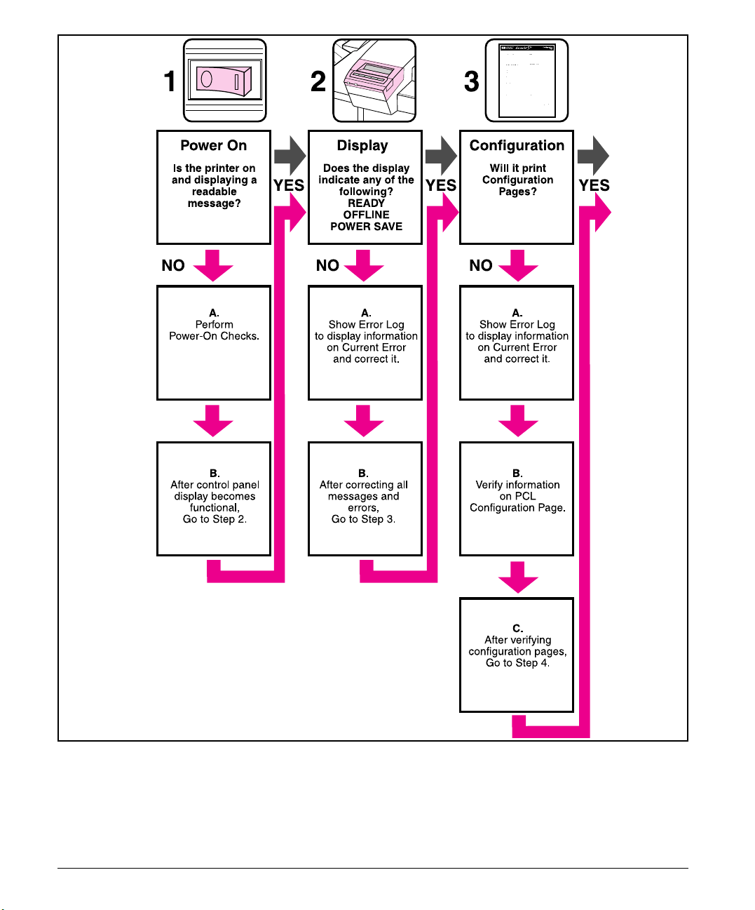
Figure 7-1 HP LaserJet 5Si / 5Si MX / 5Si Mopier Troubleshooting Process
7-4 Troubleshooting
Page 7

7
Troubleshooting
Figure 7-2 HP LaserJet 5Si / 5Si MX / 5Si Mopier Troubleshooting Process
Troubleshooting 7-5
Page 8
Power-On
Overview
It is important to have the printer’s Control Panel functional as soon as
possible in the troubleshooting process so that the printer’s diagnostics can
assist in locating printer errors.
Problem Action
1. Is AC power available at
the printer’s power
receptacle?
2. Is the printer’s ON/OFF
switch set to ON?
3. Are the printer’s fans on?
Ensure that the printer is not
in PowerSave mode
(See Figure 7-3 to locate
the fans.)
Verify.
Push the switch to the ON position.
Note: Fan operation is significant since all fans are controlled by
the printer’s DC Controller PCA. Operational fans indicate:
1. AC power is present in the printer.
2. DC power supply is functional (both 24vdc and 5vdc are
being generated).
3. DC Controller PCA ’s micro-processor is functional.
NO
YES
If the fans are NOT working, turn off the printer and remove the
printer’s Formatter PCA. Disconnect all the printer’s paper handling
options. Then turn on the printer and check the fans again.
If the fans are still not working, perform the following steps:
1. Verify that all f ans are connec ted to the DC Control ler
PCA according to Figure 7-32
2. Replace the low-voltage DC power supply.
3. Replace the DC Controller PCA.
If the fans are working but the printer’s Control Panel is blank, print
an engine test. See the section titled “Engine Test.”
If the engine test was successful, perform the following
steps:
1. Reseat or replace the cable from the Control Panel which is
connected to J203 of the DC Controller PCA (see Figure 7-34).
2. Replace the printer’s Formatter PCA.
3. Replace the Control Panel assembly.
If the engine test was not successful, replace the DC
Controller PCA.
7-6 Troubleshooting
Page 9
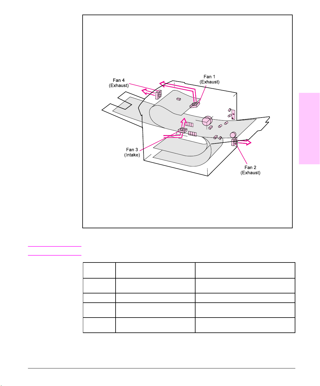
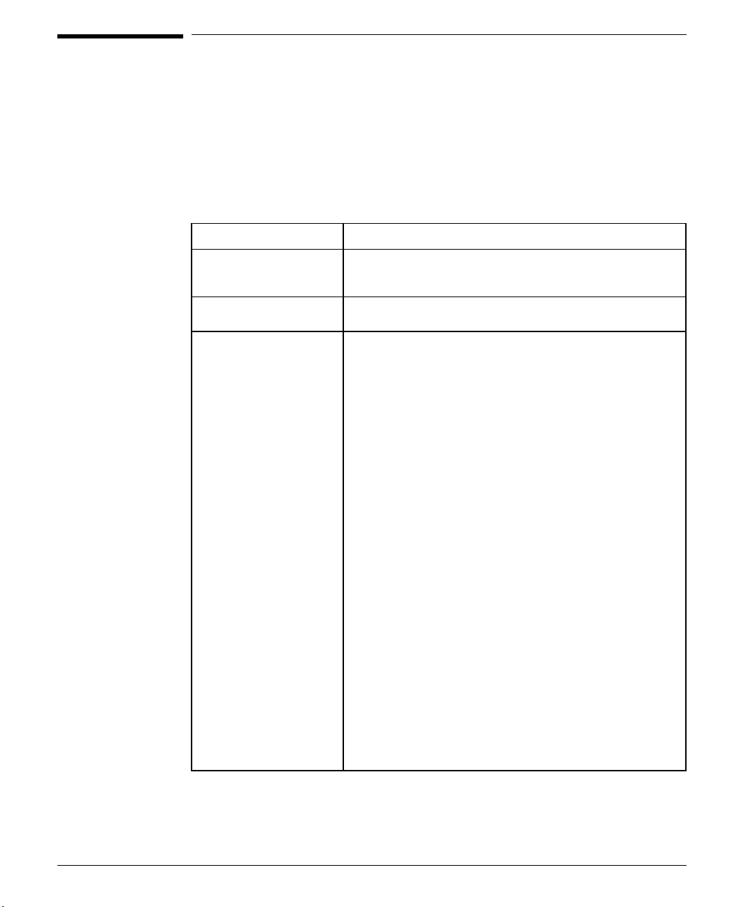
Figure 7-3
7
Troubleshooting
Note
Fan Location and Airflow
When the printer is in PowerSave mode, the fans are off.
Fan Number Fan Name
1 Laser/Scanner fan Exhaust air flows from the back of the printer,
2 Low-voltage Power Supply Lower right-hand corner of the printer.
3 Formatter (intake) Intake fan directly above the input power
4 Face-down Delivery Unit Directly above the center of the fusing
Fan Location
on the left-hand side of the fusing assembly.
receptacle.
assembly.
Troubleshooting 7-7
Page 10
Engine Test
The engine test verifies that the print engine is functioning correctly. The
Formatter PCA is completely bypassed during an engine test. This test is
very useful for isolating printer problems. The engine test prints a full page
of horizontal lines across the entire printable area, and is also useful for
checking and adjusting registration. The engine test prints from Tray 3
only, and can be activated with the Formatter PCA removed.
Note
Figure 7-4
Tray 3 must be installed and loaded with paper to perform an engine test.
Also, ensure that the EP toner cartridge is installed in the printer.
Engine Test Button Location
The engine test button is located on the DC Controller PCA. It is accessible
through a hole at the right rear of the printer.
Printing an Engine Test
To print an engine test, use a non-metallic object to press the engine test
button (see Figure 7-4). A single test page will print.
7-8 Troubleshooting
Engine Test Button
Page 11
Display
Overview
Use the printer’s Control Panel to access the error log to troubleshoot the
printer. With the printer’s test menu, you can access the printer’s error log
to display more information about the current error. The error log retains
the printer’s last 50 error messages.
Note
Refer to the section titled “Reference” for more information about correcting
printer error log messages.
The error log codes and the error on the display panel do not always
correspond. The numbers in the display panel message may not be the same
in the error log. Ensure that you refer to the correct number in the
"Reference" section.
Display and Evaluate the Error Log
If the printer cannot print or move any paper, follow these steps to display
the error log:
1 Press [Menu] until TEST MENU appears.
2 Press [Item] until SHOW ERROR LOG appears.
3 Press [Select] to show the error log.
4 Press + to scroll through the error log.
5 Write down the error messages. For example:
50 13.59.11 52700
EXTERNAL INPUT DEVIC
Error Log on Display Panel
13.11 PAPER JAM
Display Panel Message
7
Troubleshooting
50 = Error Number
13.59.11 = Error Log Code
52700 = Page Count
6 Check the error log for specific error trends in the last 10,000 printed pages.
7 Ask the customer for any observed error trends.
8 Record any specific error trends.
9 Refer to the error log table in the "Reference" section and follow the
recommended action.
10 If the display panel indicates any messages other than Ready, Offline or
PowerSave, restart at step 1. If not, go to the next section.
Troubleshooting 7-9
Page 12

Configuration
Use the configuration pages to verify the proper installation of accessories,
options, and personalities. When you print the configuration pages, the
printer checks its internal controller and I/O interface, then prints two
pages. One shows the overall printer configuration, and the one shows the
current menu settings. Refer to Figure 7-5 for information about
interpreting the configuration page. If any of the installed devices are not
shown on the configuration pages, verify that the C-Link cabling is correctly
connected and functional, and that DC power is available to the paper
handling devices (Figure 7-7). Check and reseat suspect cable connections.
If any of the cables are replaced, you must cycle the power to have the
printer recognize the device again.
To print a PCL configuration page:
1 Press [Menu] until TEST MENU appears.
2 Press [Item] until PCL CONFIGURATION PAGE appears.
3 Press [Select] to print the configuration pages.
Verify that any installed options are present on the
configuration pages.
Under Installed Personalities, look for options such as:
• Postscript (C2765A)
• 420 MB Disk (C2965A)
• SIMM types RAM or ROM and sizes.
7-10 Troubleshooting
Verify that the options which are physically installed in your printer are
reflected in the PCL configuration page. If an installed device is not shown
on the PCL configuration page, check the following table.
Page 13

Device Action if installed and not detected
Duplex Unit Power-off, reseat or replace duplex unit and power-on.
Envelope Feeder Power-off, reseat or replace envelope feeder and power-on.
Device 1
2000 Sheet Input Unit
Device 2
Multi-Bin Mailbox
Device 3
Stapler Module
Verify C-Link cables are installed correctly, see Figure 7-7.
Remove all C-Link connections and visually inspect for connector
damage on the cable pins and connector ends.
Try using a different cable to connect the problem device directly to
the External Paper Handling Controller. All C-Link cables are wired
the same, but are different lengths.
If a device is not recognized, replace device controller or defective
C-link cable.
Device 1
2000 Sheet Input Unit
Device 2
Multi-Bin Mailbox
Verify AC power is present in the 2000 Sheet Input Unit.
Note: The tray will not lift if C-link cable is not connected properly to
External Paper Handling Controller.
Verify that the external DC power supply is receiving power.
Verify that the external DC power supply output is connected to the
Multi-Bin Mailbox controller.
Note: The Multi-Bin Mailbo x wi ll not appear on the PCL
configuration page without the C-Link cables properly installed or
external power applied.
Replace external DC power supply.
Replace Multi-Bin Mailbox controller.
After verifying that the PCL configuration pages accurately reflect the
installed devices, proceed to the section titled “Image Quality.”
7
Troubleshooting
Troubleshooting 7-11
Page 14

Figure 7-5
Configuration Page Illustration and Key
The default S/N is
AAXXYY99999. To set
the correct S/N, refer to the
SERVICE MODE procedure
in Chapter 3 of this manual.
Formatter and firmware’s
datecode and version
number.
The three most recent
error log messages
display here.
The MIO Block shows
network communication.
See Figure 7-9.
Check the
installed
memory to see
if it corresponds
with what is
physically
installed in the
printer.
All the paper handling
devices that are
physically present
should be listed in this
section. Verify that
each device is
connected according
to Figure 7-6.
When configured
correctly:
7-12 Troubleshooting
Device 1=2000 sheet
Device 2=Mailbox
Device 3=Stapler
Configuration Page Example
Page 15
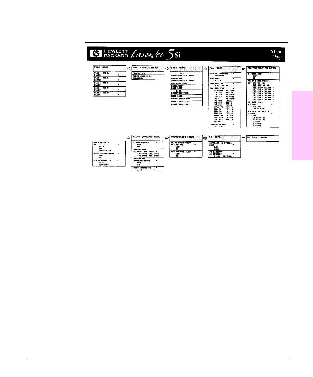
Figure 7-6
Menu Page Example
7
Troubleshooting
Menu Page Example
Troubleshooting 7-13
Page 16

Figure 7-7
Communications Link (C-Link) Cables
Note
Communications Link (C-Link)Cables, Supported Daisy Chain Connections
All C-Link cables have a single dot molded into the device output connector
cable end, and two dots molded into the device input connector cable end.
The devices may not be recognized by the External Paper Handling
Controller if the cables are not connected exactly as shown in Figure 7-7.
It is important that the C-Link cables are installed in the supported daisy
chain configuration as shown in Figure 7-7. This is so that the devices are
recognized and correctly reported on the error log.
Example: In the error log message "13.12.03", the last two digits ".03"
indicate that Device 3 has failed in the supported configuration:
Device 1 = 2000 Sheet Input Tray
Device 2 = Multi-Bin Mailbox
Device 3 = Stapler Module
It is possible, but not recommended, to attach the C-Link cables in other
configurations. This will rearrange the supported device numbering. Keep
in mind this configuration when evaluating the error log.
7-14 Troubleshooting
Page 17
Image Quality
When you are working with customers, obtain a print sample before you
begin troubleshooting their printer. Ask the customer to explain the quality
they expect from the printer. The print sample will also help clarify the
customer’s explanation.
Problem Action
1. Do you have a print
sample?
2. Does the problem repeat
on the page?
3. Is the toner cartridge full
and is it manufactured by HP.
4. Is the printer clean? Perform the cleaning procedure described in Chapter 4 of this
5. Is the customer using
print media that meets all
HP paper specification
standards?
6. Is the print sample similar
to those in the Print Quality
Tables in the “Reference.”
section?
7. Is the problem on the
drum or transfer roller?
Obtain a print sample from the customer.
Use the Repetitive Defect Ruler in the "Reference Section."
Check the toner cartridge using the check list on next page.
manual.
For more information about HP’s paper specification standards, see
Chapter 1 of this manual and the
Specification Guide.
Compare and perform the actions recommended in the Print
Quality Tables.
Perf orm the "Half Self Test" in the "Reference Section" to determine
where the defect is.
HP LaserJet Family Paper
7
Troubleshooting
If the defect is on the drum, replace the Toner cartridge High
Voltage Supply.
If it is not on the drum, replace the transfer roller.
Troubleshooting 7-15
Page 18

Check the Toner Cartridge
Image formation defects are often the result of toner cartridge problems. If
there is any doubt, always replace the toner cartridge before troubleshooting
image defects.
Use the following check list to ensure that the toner cartridge is still
operable.
• Ensure that the toner cartridge has toner.
Full toner cartridge weight = 3000 grams (106 oz)
Empty weight = 2300 grams (80.5 oz)
• Check the expiration date of the toner cartridge (stamped on the cartridge
box).
• Check the toner cartridge to see if it has been disassembled or refilled.
• Ensure that the toner cartridge is seated properly in the printer cavity.
• Inspect the cartridge for leaking toner through worn seals. (If the drum has
been manually rotated it may have caused internal damage and toner spills
may result.)
Note
Toner Cartridges are rated for 15,000 images at 5% coverage. It is possible
to wear out the gears and the cartridge seals before TONER LOW is displayed if
the 15,000 image expectancy is exceeded.
• Check the surface of the photosensitive drum in the cartridge to see if it has
been damaged or scratched. Touching the drum will contaminate the
photosensitive surface and may cause spotting and defects during printing.
• White areas on the page may indicate that the drum has been exposed to
light for too long. If white areas appear, stop the printer and wait a few
minutes. This should eliminate most defective images. If not, the toner
cartridge may be placed in a dark environment for several days, which may
restore some life to the drum.
Faulty Image Examples
The “Reference” section contains Image troubleshooting and sample image
defects and their possible causes. Since there are many variables in the
printing process, it is possible to encounter image defects that are not shown
in the examples. If you find a defect that is not depicted, record the probable
cause along with the printing environment conditions and save a copy of the
defect for future reference.
7-16 Troubleshooting
Page 19

Error Log
Use the error log to diagnose and troubleshoot printer errors and
intermittent failures.
Print and Evaluate the Error Log
The printer’s internal error log stores the last 50 errors and can be printed
at any time. To print the error log:
• Press [Menu] until TEST MENU appears.
• Press [Item] Until PRINT ERROR LOG appears
• Press [Select] to print the error log.
After printing the error log:
• Check the error log for specific error trends in the last 10,000 printed
pages.
• Ask the customer for any observed error trends.
• Record any specific error trends.
• Refer to the error log table in the “Reference” section of this chapter to
interpret error log codes.
7
Troubleshooting
Error Log Interpretation
The error log is the key tool in troubleshooting printer problems. Figure 7-8
shows a typical error log. The error log shows the current page count at the
top center of the page, with the printer’s serial number directly to the right
of the page count. The left column is the error sequence number, with the
error listed at the top (the highest sequence number is the most recent error
logged). The next column is the page count at the time of the error, and the
last column is the Personality (PCL or PostScript) column or the Jam Cause
at the time of the error.
The error log records all errors in a different format than the Control Panel
Display. For example, should a 50.1 FUSER ERROR / CYCLE POWER be
displayed on the Control Panel Display, the error log will record a 50.02.01
error, with the 02 signifying that 2 sensors were blocked. Likewise, when a
13.1 through 13.9 are displayed on the Control Panel, the error log will
record a 13.0x.01 through 13.0x.09, where x = the number of sensors blocked
in the printer.
When an error is detected in an Optional Paper Handling Device, a 13.11,
13.12 or 66.xx.yy will be posted to the Control Panel.
Troubleshooting 7-17
Page 20
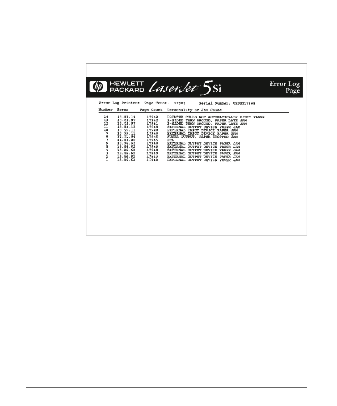
Figure 7-8
Whenever a 13.xx appears on the Control Panel, a good practice is to clear
all the paper from the printer, take the printer offline, and print the error
log. If you cannot print the error log, you can still display it on the display
panel. Write the error next to the last error logged. The last error is the
error at the top of the error log printout with the highest number in the
leftmost column.
7-18 Troubleshooting
Error Log Page
To interpret the error log:
• Each individual entry in the log is called an "ERROR," with all errors
occurring at the same page count an "EVENT." Read the Recommended
Action for each error comprising an event to gain a clear picture of what
took place during that event. Events usually conclude with a timeout or
no response from device (Error 66.nn.nn in printer logs) which requires a
power cycle of the print engine.
• It is assumed that any Paper Handling Devices are connected as shown
in the C-Link Cable Diagram (Figure 7-7). The errors will be logged with
different device numbers if any non-standard cabling is installed.
• Use the error log table in the “Reference” section of this chapter to
associate errors in the error log with the Control Panel error message.
Follow the Recommended Action listed in the table for each error or
event.
Page 21
Communication
Ask the customer to run a print job from the host system. If the print job is
successful, proceed to the following step, “Verification.”
Verify Communication
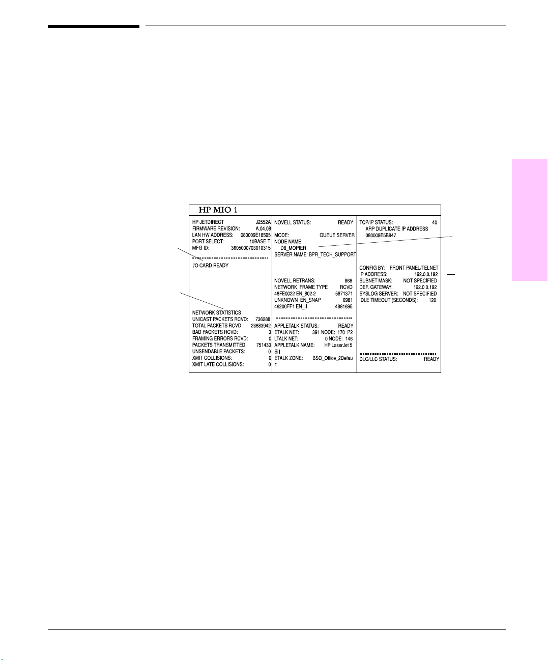
Figure 7-9
Print the PCL configuration page and study the HP MIO block. The MIO
block will appear on the bottom portion of the configuration page. An
example of a properly operating MIO block appears in Figure 7-9.
Node Name
I/OCard
Ready
IP Address
Network
Statistics
MIO block on Configuration Page
• If the MIO Jet Direct Card has successfully powered up and completed its
internal diagnostics, the "I/O CARD READY" message will appear. If
communication is lost, an "I/O NOT READY" message appears followed by a
two digit error code. Consult the HP JetDirect Network Interface
Configuration Guide for further details and recommended action.
7
Troubleshooting
• The "Network Statistics" column indicate that the network activity has been
occurring. Bad packets, framing errors, un-sendable packets and collisions
should be minimal. If a high percentage (greater than one percent) of these
occur, contact the network administrator. All of the statistics are set to zero
when the printer is powered-off.
• The "Novell Status" block should state the Novell printer server name to
which the printer is connected. If the node name reads "NPIxxxxxx"
(xxxxxx=last six digits of the MIO’s LAN address), the MIO card has not
been configured for a Novell server. This could indicate that the card is
Troubleshooting 7-19
Page 22

operating under a IPX protocol other than Novell. Consult with the
network administrator if the Node Name is not present.
• In the TCP/IP protocol block, the default IP address is "192.0.0.192." It is
acceptable to operate the printer with this default address. The error
message, "ARP DUPLICATE IP ADDRESS" may appear in this block. This
is also an acceptable error code if the TCP/IP protocol is not being used.
Please check with the network administrator to determine the correct IP
Address for the printer.
Verify Host System Operation
Try to print to another known working printer or move the failing printer to
a known working location. Verify that the correct driver is installed and
operating properly. Check with HP Service and Support in the User’s
Manual to obtain the latest Windows and PostScript drivers.
Note
To display the printer driver version:
In the printer driver, select the Print Quality tab and click on About to
display the printer driver revision level.
Verify Network and Server Operation
• Try to print the job to the printer’s parallel port.
• Try to print from the host system through the network to another printer.
Contact the network administrator for assistance.
7-20 Troubleshooting
Page 23

Verification
Paper Path Test
Using the error trend information from Step 5 (Error Log), you may verify a
specific printer paper path with the paper path test. You must first set the
desired paper destination in the configuration menu and then select the
paper path test. The paper path test menu will allow you to select the
desired paper source and number.
Note
In order to perform the paper path test, the printer must be configured to
mailbox mode. If the printer is not in mailbox mode, ask the JetAdmin
administrator to change the configuration to mailbox mode to complete this
test.
To perform a paper path test:
Set Destination and Duplex first:
• Press [Menu] until CONFIGURATION MENU appears.
• Press [Item] until PAPER DESTINATION appears.
• Press [+] to cycle selections until the desired paper destination appears.
• Press [Select] to select the desired destination for the Paper Path Test.
• To set duplex, press [Menu] until CONFIGURATION MENU appears.
• Press [Item] until 2 SIDED = XX appears.
• Press + to select duplex or single side.
Set Source and number of pages last:
• Press [Menu] until TEST MENU appears.
• Press [Item] until PAPER PATH TEST appears.
• Press [Select].
• Press [+] to cycle selections until the desired paper source appears.
• Press [Select].
• Press [+] to cycle selections until the desired number of images appears.
You can choose 1, 10, 50, 100 or 500 copies.
• Press [Select] to perform the Paper Path Test.
7
Troubleshooting
Troubleshooting 7-21
Page 24

Figure 7-10
Note
7-22 Troubleshooting
Paper Path Test Source and Output Selection
Customer Print Job
Ask the customer to send a print job from the problem source(s) to the
problem destination(s). Try to recreate the paper jam errors by having the
customer do typical print jobs and the type of print job that has been
causing the paper jams.
When verifying print jobs, ensure that all of the settings are selected as
desired. Keep in mind that application settings take priority over Driver
settings, which take priority over the the printer control panel settings. If a
single setting is not present in the application, but is set in the driver, that
will override the front panel settings.
JetAdmin does have capabilities to override paper types and sizes and
certain conditions.
Page 25

Reference
Control Panel Messages and Errors
Printer messages displayed on the control panel provide five categories of
information. Each message category is assigned a priority. If more than one
condition occurs at the same time, the highest priority message is displayed.
When it has been cleared, the next priority message will be displayed, and
so on. The displayed messages and their priorities are:
Note
• Catastrophic System Messages
• Service Messages
• Error Messages
• Attendance Required Messages
• Device Status Messages
Error, Service, and Catastrophic System messages are preceded by a
number designation. Device Status and Attendance Required messages
(except for paper jam messages) do not have a number designation.
The Error Log Table is organized by the display panel messages. All of the
alphabetical messages are listed first, followed by numeric display panel
messages. The error log codes (the second column) are in no order. They
are merely listed with the associated display panel message.
7
Troubleshooting
Troubleshooting 7-23
Page 26
Error Log Table
Message Error
Description Recommended
Log
Category/
Message
ACCESS DENIED Status After an attempt to select a locked-out
CANCELING JOB Status The printer is canceling the currently active
CLEAR JAMMED STAPLE Attendance
CLEARING PAPER FROM
THE PRINTER
CLOSE PRINTER COVER Attendance
COPIES XX OF Y Status This message indicates the progress of the
Required
13.10.03
Status The printer is attempting to remove unusable
Required
function, this message displays for
approximately 2 seconds.
job.
Staples are jammed in the stapler. To clear the jam, open the Stapler
paper. This may oc cur after you clear a paper
jam.
One of the printer’s doors or its cover is not
latched or seated properly. Interlock switches
are connected to each door and the cover.
For the Top Cover and Fuser Door, close
SW1. The Ri ght Paper Path Door enables
photosensor PS3 on the Pickup PCA of the
Paper Input Unit (PIU).
current job.
Action
The JetAdmin Administrator
controls the control panel lockout
feature. Request from the
administrator to unlock function.
No action required. If message
displays for over 5 minutes, cycle
power. An extremely large print
job with detailed graphics may
take up to five minutes to cancel.
Top Cover Assembly by pressing
the green tab with your thumb
and pulling the green circular tab
with your forefinger (refer to
Figure 7-11). Remove loose or
damaged staples from the stapler .
Push the circular tab to snap it
back into place. Close the Top
Cover Assembly.
NOTE: If any staples are
removed while clearing a staple
jam, up to 12 documents may not
be stapled when printing resumes
because the stapler must reload.
Check the Staple Cartridge.
Replace it as required. Replace
the Stapler Top Cover. Replace
the entire stapler as required.
No action required.
Ensure the following are closed:
Top Cover, Rear Fuser Access
Door, and Right Paper Path
Access Door (below Tray 1).
No action required.
7-24 Troubleshooting
Page 27
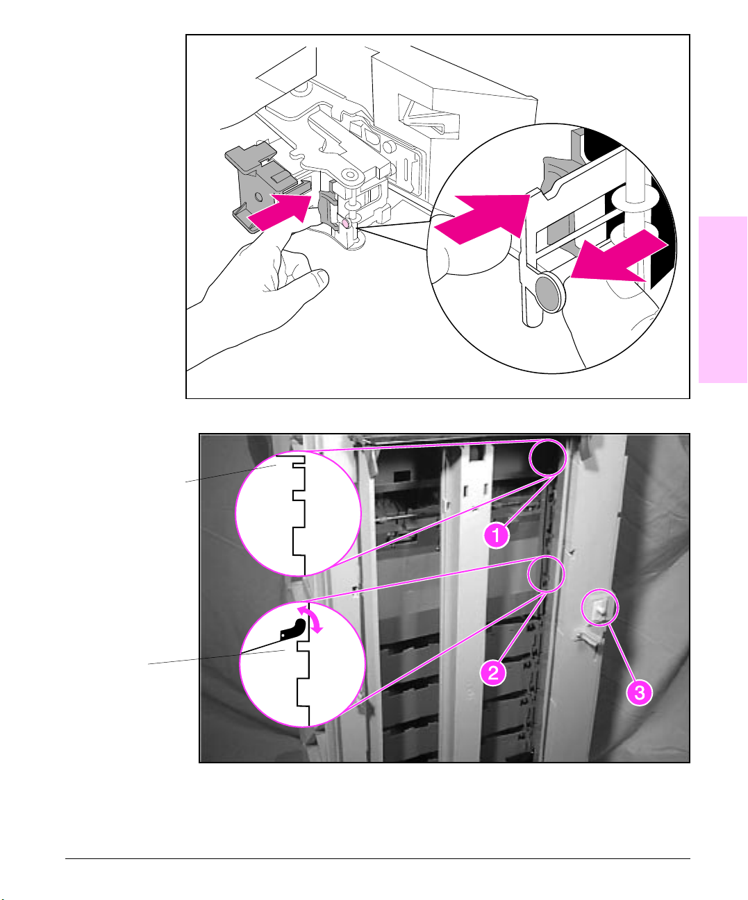
Figure 7-11
Figure 7-12
7
Troubleshooting
Clearing Staple Jams
"Home" position gap.
When the output bin
is full, the flag blocks
the gap.
Scanbar and MBM Interlock Switch (SW1).
1 and 2 - Scanbar gaps. 3 - Multi-Bin Mailbox Interlock Switch
Troubleshooting 7-25
Page 28
Message Error
Description Recommended
Log
Category/
Message
ENGINE TEST Status This message displays after the engine test
FORMFEEDING
(The [On Line] LED flashes.)
HP MIO 1 INITIALIZING Status This message displays while the upper HP
HP MIO 2 INITIALIZING Status This message displays while the lower HP
HP MIO 1 NOT READY Status The upper MIO card is not ready. One of two
Status A form feed is in process. No action required. When the
button is pressed and indicates that the
engine test is in process. If the test fails, an
error or attendance message displays.
MIO card initializes. The printer supports I/O
switching and remains online, but the
channel is not active during initialization.
NOTE: Since older MIO cards cannot
remove the message, the printer will remove
the message after a 5-minute timeout.
MIO card initializes. The printer supports I/O
switching and remains online, but the
channel is not active during initialization.
NOTE: Since older MIO cards cannot
remove the message, the printer will remove
the message after a 5-minute timeout.
situations may occur. First, the parallel port
and the lower MIO card may continue to
operate nominally. If the upper MIO card is
operating correctly and communicating with
the network, this message will disappear
after approximately one minute. No action is
required. Second, if the upper MIO card is
unable to communicate with the network, this
message will display for five minutes and
then disappear. In this case, the printer is not
communicating with the network, even
though the message is no longer displayed.
Action
No action required. Refer to the
Power On section for more
information about performing an
engine test.
paper reaches the destination
output bin, the [Ready] message
displays and the [On Line] LED
returns to a steady state.
No action required. If the
message displays after five
minutes, a problem may exist in
the network card, the network
configuration, or with the host. For
more information about the MIO
card, refer to your network
documentation.
No action required. If the
message displays after five
minutes, a problem may exist in
the network card, the network
configuration, or with the host. For
more information about the MIO
card, refer to your network
documentation.
The problem may be a bad MIO
card, bad cable or connection on
the network, or a network
problem. For more information
about the MIO card, refer to your
network documentation. Verify
that the product numbers for the
MIO card is supported by printer.
7-26 Troubleshooting
Page 29
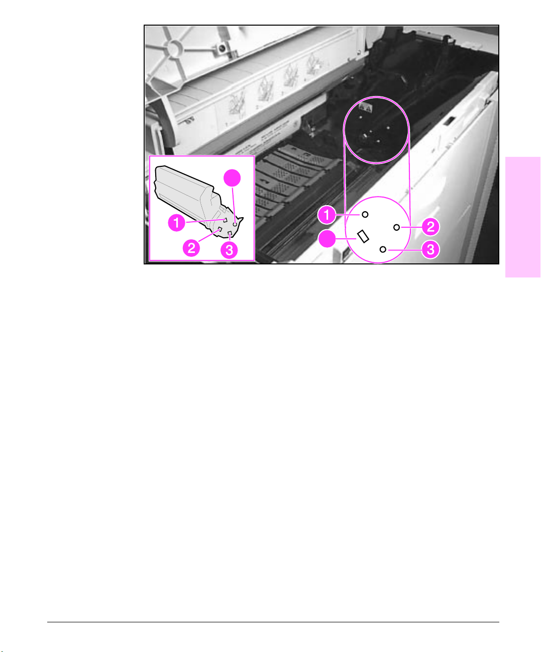
Figure 7-13
7
Troubleshooting
High-voltage Power Supply contacts
1. Primary Charging Roller Connector
2. Toner Registration/Toner Sensor
3. Developing Roller Bias Connector
4. Drum Ground Connector
Troubleshooting 7-27
Page 30
Message Error
Description Recommended
Log
Category/
Message
HP MIO 2 NOT READY Status The lower MIO card is not ready. One of two
INPUT DEVICE FEED
PATH OPEN
INPUT OPERATION
CONDITION xx.1y
Attendance
Required
Attendance
Required
situations may occur. First, the parallel port
and the upper MIO card may continue to
operate nominally. If the lower MIO card is
operating correctly and communicating with
the network, this message will disappear
after approximately one minute. No action is
required. Second, if the lower MIO card is
unable to communicate with the network, this
message will display for five minutes and
then disappear. In this case, the printer is not
communicating with the network, even
though the message is no longer displayed.
An external input device such as the
2000-Sheet Input Tray (Tray 4) is disrupting
the paper path. The opening and clos ing of
the Tray 4 Vertical Transfer Door should
cause this message to be displayed (the
closed door "blocks" PS35).
An external input device has a condition that
needs to be corrected before printing can
continue.
See error log 13.17.11 -13.59.11
Action
The problem may be a bad MIO
card, bad cable or connection on
the network, or a network
problem. For more information
about the MIO card, refer to your
network documentation. Verify
that the product numbers for the
MIO card is supported by printer.
Check feed path, covers and
doors on external input device(s).
Check PS35 on the vertical
transfer assembly.
Check the indicated input device
and correct the error condition.
Cycle power and print PCL
configuration pages to verify all
devices are shown in printout.
See Figure 7-5.
INPUT TRAY = ALL TRAYS Status The printer will pull paper from all available
INSTALL TONER
CARTRIDGE
INTERNAL TEST Status The printer is executing a non-printing self
Attendance
Required
paper trays.
The toner cartridge is missing or installed
incorrectly. The print engine detects the
presence of the toner cartridge by reading
the voltage at the Toner Registration/Toner
Sensor on the High-voltage Power Supply.
For sensor location on the power supply, refer
to Figure 7-13. The contact can be ac ces s ed
from the right-hand side wall of the toner
cartridge cavity in the printer.
test.
7-28 Troubleshooting
No action required.
Ensure the toner cartridge is
seated properly, or install a new
toner cartridge, ensuring it is
seated properly. If the error
persists: Check functionality of
the toner cartridge and
High-voltage Power Supply
contacts (refer to Figure 7-13).
Replace the toner cartridge.
Replace the High-voltage Power
Supply.
No action required. If this
message displays for over three
minutes, first cycle power. If this
persists, verify that the Formatter
connections are secure. Then
remove all optional SIMMs and
MIO(s).
Page 31

Message Error
Log
Description Recommended
Action
Category/
Message
LOAD TRAY X or LOAD
ENV FEEDER
type> <paper size>
MANUAL FEED TRAY 1
<media type> <paper size>
MOPY XX OF Y from Tray n Status This message indicates the progress of the
OFFLINE Status The printer is offline and cannot receive data. Press [Online] .
OUT OF STAPLES Attendance
OUTPUT DEVICE
DELIVERY PATH OPEN
<media
Attendance
Required
Attendance
Required
Required
Attendance
Required
The printer received a request for a media
type and size that is not currently installed in
the printer.
The printer received a request for a media
type and size manually fed from Tray 1.
current job.
The staple cartridge is empty. Staples are
detected by a photosensor and flag located
beneath the staple cartridge access slot.
Inserting a cartridge with staples pushes
down this flag.
One of the printer’s interlock switches is not
set properly. Thi s mes sage di spl ays for one of
two reasons:
1. An external output device, such as the
Multi-Bin Mailbox, is disrupting the paper
path. Switch SW1, the interlock switch, is not
depressed (callout 3, Figure 7-12).
2. The stapler’s top cover is open. Two
interlock switches detect whether the
stapler’s top cover is closed (refer to Figure
5-21).
Load the indicated tray with the
correct media, or override the
media type and size through the
printer’s Control Panel for that
print job.
Note: If paper is loaded when the
printer is in POWER SAVE, it may
not be recognized. Open and
close the affected source when
printer is in READY mode.
Load the correct media in Tray 1.
If the correct media is already
loaded, press [Online] so the
printer will use that media.
Note: If paper is loaded when the
printer is in POWER SAVE, it may
not be recognized. Open and
close the affected source when
printer is in READY mode.
No action required.
Replace the staple cartridge.
NOTE: The stapler will retain
some staples; do not remove
them. Remove the cartridge.
Verify that the flag beneath the
staple cartridge slot moves freely.
If it is damaged, replace the
stapler’s top cover. Replace the
Stapler Assembly.
Ensure the mailbox is installed
tightly against the printer
(especially at the top of the
mailbox). Carpeting and/or
uneven flooring may cause the
top of the mailbox to move away
from the printer, which causes
this error to occur. Verify that
Switch SW1 is working properly
(callout 3, Figure 7-12).
Close the stapler’ s top cover. The
printer will reset. Verify that the
switches in the stapling unit are
correctly wired and functional.
Perform continuity checks with
the switches.
7
Troubleshooting
Troubleshooting 7-29
Page 32

Message Error
Description Recommended
Log
Category/
Message
OUTPUT OPERATION
CONDITION x.yy
PAPER DESTINATION =
ALL BINS
PERFORM USER
MAINTENANCE
PRESS SELECT TO
CANCEL JOB
PRINTING
CONFIGURATION PAGE
PRINTING DEMO PAGE Status This message displays while the printer
PRINTING DISK
DIRECTORY
PRINTING ERROR LOG Status This message displays while the printer
PRINTING FONT LIST Status This message displays while the printer
PRINTING PAPER PATH
TEST
PROCESSING JOB FROM
ENV FEEDER
Attendance
Required
Status The printer will output paper to all available
Status The printer requires a formal maintenance
Status This message displays to confirm that you
Status This message displays while the printer
Status This message displays while the printer
Status This message displays during a paper path
Status The printer is processing data from the active
An external output device has a condition
that needs to be corrected before printing
can resume.
x = output device
0 = Paper Handling Controller
2 = Multi-Bin Mailbox
3 = Stapler
yy = condition code
For the Multi-Bin Mailbox: 01 = Face-Up bin
not installed.
bins.
procedure.
canceled the currently active job.
prints the configuration pages.
prints a demo page.
prints an optional disk accessory directory.
prints the error log.
prints a font list.
test. This test can print 1, 10, 50, 100, or 500
pages.
I/O channel. Some data is printed and some
data cannot be printed, such as downloading
fonts or macros. The media source is the
Envelope Feeder.
Action
Cycle power and print PCL
configuration pages to verify all
devices are shown in printout.
See Figure 7-5.
Check the indicated output device
and correct its condition. Check
C-Link Cables for proper
connection. For the Multi-Bin
Mailbox/Mailbox with Stapler,
ensure that the Face-Up Bin is
properly installed.
No action required.
Perform the required
maintenance in accordance with
chapter 4. Access the
Configuration Menu, and select
SERVICE MESSAGE=OFF.
Press [Select] to cancel a print
job. This may take up to 5 minutes
to cancel the print job. Press any
other key to continue.
No action required.
No action required.
No action required.
No action required.
No action required.
No action required. To stop the
test, access the JOB CONTROL
menu, and select CANCEL JOB.
No action required.
7-30 Troubleshooting
Page 33

Message Error
Description Recommended
Log
Category/
Message
PROCESSING JOB FROM
TRAY x
READY Status This is the default message. The printer is
REMOVE PAPER FROM
TOP OUTPUT BIN or
REMOVE PAPER FROM
OPTIONAL OUTPUT BIN n
RESTORING FACTORY
SETTINGS
SELECT LANGUAGE Status This message displays after pressing and
SERVICE MODE Status This message displays after accessing the
SKIP DISK LOAD Status This message displays for approximately one
STAPLER ALIGN ERROR Attendance
Status The printer is processing data from the active
Attendance
Required
Status This message displays during a COLD
Required
I/O channel. Some data is printed and some
data cannot be printed, such as downloading
fonts or macros. The media source is the
indicated tray.
x = tray number
1 = Tray 1
2 = Tray 2
3 = Tray 3
4 = 2000-Sheet Input Unit
ready to use.
The destination output bin is full and the
printer will not send anymore pages to that
bin.
RESET. All printing environment parameters,
personality and device defaults return to their
factory default settings. When it is completed,
the printer displays [On Line] or [Ready].
holding [Select] while powering on the
printer.
Service Mode.
second after powering on the printer while
pressing and holding [Menu]. Indicates that
the disk-based system execution is disab l ed.
The printer continues its normal initialization
process.
The paper is misaligned in the stapler and
cannot be stapled.
Action
If an incorrect tray is displayed,
check the tray selected and the
type settings. If printer does not
respond after pressing the control
panel keys, cycle power to clear
the error.
Note: If paper is loaded when the
printer is in POWER SAVE, it may
not be recognized. Open and
close the affected source when
printer is in READY mode.
No action required.
Remove the paper from the
indicated output bin. For a
mailbox with a stapler: Check the
bin full actuator at the bottom of
the stapler housing. Replace as
required. Check the stapling bed
and cables. Replace as required.
The stapling bed includes cables .
Replace the entire stapler.
No action required.
Press [ + ] to scroll through the
available languages. Press
[Select] to activate the displayed
language.
To display the Service Mode
menus, press [Item]. Press
[Online] to exit the Service
Mode. For more information
about the Service Mode, refer to
Chapter 3.
To reset the printer, cycle power,
and do not press and hold
[Menu].
Remove the paper from the
stapler and resend the job. Check
for paper in the actuator near the
stapler bed. Replace the stapler.
7
Troubleshooting
Troubleshooting 7-31
Page 34

Message Error
Description Recommended
Log
Category/
Message
STAPLER LIMIT REACHED Attendance
Required
TONER LOW Attendance
Required
TRAY n EMPTY Status The paper tray is empty. Paper is sensed in
The stapler has reached its maximum of 20
sheets to be stapled.
The toner cartridge is running out of toner.
NOTE: Check the Configuration Menu. If
TONER LOW=CONT, the printer will continue
printing; but if TONER LOW=STOP displays,
the printer will stop printing and go off line.
the tray by triangular-shaped, black plastic
flags and photosensors. If paper is not in a
tray, the flags will rotate through an access in
the paper tray. When paper is present, the
flags are blocked from rotating through this
access.
Action
Remove the 20 sheets from the
bin. The printer will automatically
continue and staple the remaining
pages separately.
Shake the toner cartridge or
replace it. If TONER LOW
remains displayed and no other
conditions are present, printing
will automatically continue, but
the print quality will gradually
degrade. If the message persists:
check the contact points on the
left end of the toner cartridge and
inside the toner cartridge cavity
(refer to Figure 7-13 ) and replace
the toner cartridge. Replace the
High V ol tage PCA.
The printer will still function. Load
paper, if desired. If the message
is intermittent or persists with
paper in the tray: Ensure the
black triangular-shaped paper out
flag is not stuck in the down
position by rough media. Do this
before opening the tray. To check
this flag without opening Tray 2,
remove the Duplexer if it is
present. Open the Front Access
Door (refer to Figure 1-2). This
provides you with a clear view of
the Tray 2 paper out sensor flag
(refer to Figure 7-14 ).To check
this flag without opening Tray 3,
use a flashlight to observe the
paper out flag. If either paper flag
is damaged, replace the paper
flag or replace the paper input
unit. If the printer is using Tray 2
or 3 and the message is
accompanied by a clicking noise
every few seconds, replace the
Paper Input Assembly.
7-32 Troubleshooting
Page 35

Figure 7-14
Figure 7-15
7
Troubleshooting
Tray 2 (1) and Tray 3 (2) Paper Out Flags
Vertical Transfer Door Closed Sensor (PS35)
1. PS35 Vertical Transfer Door Switch
2. Drive Gear
3. Vertical Transfer Door Registration Sensor Flag PS31
4. Vertical Transfer Door Paper Jam Sensor Flag PS32
Troubleshooting 7-33
Page 36

Message Error
Log
Description Recommended
Action
Category/
Message
TRAY 4 EMPTY Status Tray 4 is empty or not lifting. Under normal
operating conditions, when Tray 4 is closed
the paper stack lifts until the paper is directly
beneath Tray 4’s feed rol lers. P hotos ens or
flag PS34, the paper surface photosensor,
determines when the paper stack is lifted to
its feed position. Mechanically, Tray 4 lifts
when the tray is closed. When closed, a
drive gear on Tray 4 engages with the drive
mechanism located on the back-side of the
2000-Sheet Input Unit. A pilot locating pin
and bushing are present to ensure that the
gear from Tray 4 and the drive motor gear
assembly engage properly. Once engaged,
the rotating gears use a cable lift mechanism
to lift Tray 4’s paper stack.
Tray 4 is not lifting and/or makes abnormal
noises.
Tray 4 is partially lifting or not lifting at all
because paper loaded on the left side of the
tray is blocking upward movement.
Microswitch SW31 is defective or
disconnected (callout 2, Figure 7-23).
TRAY n OPEN Status The indicated paper tray is open. The printer will still function. Close
WARMING UP Status The Fuser is warming up and the printer is
not ready. It may be necessary to display the
error log to determine if more information is
available to assist you in troubleshooting.
V erify the 2000-Sheet Input Tray
is present under the Paper
Handling Options of the PCL
configuration pages. To w atch
Tray 4 lift, Open the transfer door.
Open and close Tray 4. With the
transfer door open, defeat the
transfer door closed photosensor
(PS35) by pushing in on the
sensor flag (callout 1, Figure
7-15). See if Tray 4 is lifting. The
white drive gear on the right-hand
side of the transfer door should
be rotating. If it is not rotating,
verify the cable connections
between Main Motor (M1), the
Tray 4 Controller PCA, and the
Tray 4 Power Supply (refer to
Figure 6-58, callout 1 and Figure
6-56, callout 1). Verify the lift
cables are not broken (refer to
Figure 7-24). Replace the
2000-Sheet Input Unit if the lift
cables are broken. Tray 4 is not
seated into the gear when lifting.
Check the white bushing on Tray
4, which is located on a steel
locating pin. If the bushing is
cracked or broken, replace the
bushing, and replace the gear
assembly. Remove any paper
from the left side of Tray 4.
Replace the paper surface
sensing switch (SW31) located at
the center top of the 2000-Sheet
Input Unit (callout 2, Figure 7-23).
the tray if desired.
Wait until the printer signals ready
to accept data. The us er may
access the menus before the
printer goes online. If this
message remains displayed,
separate all accessories from the
printer. Cycle power and recheck
messages. If no error, replace
accessories one at a time.
Recycle power. If message
persists, replace the F ormatter .
Replace the DC Controller.
Replace the Power Supply.
7-34 Troubleshooting
Page 37

Figure 7-16
7
Troubleshooting
PS31 Tray 4, Transfer Door Registration Photsensor
PS32 Tray 4, Transfer Door Paper Jam Photosensor
PS2 Paper Input Unit Paper Jam Photosensor
PS1 Registration Assembly Photosensor
PS1403 Fusing Exit Photosensor
PS1402 Face Down Delivery Paper Jam Photosensor.
PS Entry Flipper Assembly of Multi-Bin Mailbox
Sensor Flag Locations Along the Paper Path
Troubleshooting 7-35
Page 38

General Paper Path Troubleshooting
Paper jams occur in the printer when paper does not either reach or clear a
photosensor along the printer’s paper path in a specific amount of time. If a
paper jam occurs, a "13.xx PAPER JAM" message is displayed on the printer’s
Control Panel. The following lists general questions you should ask and
topics you should explore prior to troubleshooting:
General Paper Path Troubleshooting Questions
Problem Action
What is the frequency of the
paper jams (e.g. continuous,
one jam per 100 pages, one
jam per 1000 pages, etc. . .)?
Do paper jams only occur
when the paper is fed from a
particular paper input source
(e.g., Tray 1, T r a y 2, Tray 3,
Tray 4 or Envelope Feeder)?
Do jams only occur when
paper is output to a specific
output bin (e.g., face-down
output bin, face-up bin,
mailbox bin, duplex
operation, stapler)?
Do paper jams occur with a
specific type of media?
Where does the leading
edge of the first sheet of
paper in the printer’s paper
path stop when a jam
occurs? Are any sheets of
paper physically damaged or
torn?
Is the customer loading the
paper trays correctly?
Is the customer overfilling
the paper trays?
Are the paper tray guides
set correctly?
Does the printer need
cleaning?
When was the User
Maintenance performed on
the printer?
Verify with customer. Print or Show Error Log to determine paper
jam history. See the Display and Error Log Sections of this Chapter
and evaluate error log.
See Verification Section of this chapter and use Paper Path Test to
isolate problem.
See Verification Section of this chapter and use Paper Path Test to
isolate problem.
Try known good media. See the HP LaserJet Printer Family Paper
Specifications Guide. Note that the guide is bundled with the
Service Manual.
Attempt to duplicate. See Verification Section of this chapter and
use Paper Path Test. Inspect the paper path and all paper path
mechanical assemblies prior to the leading paper jam.
Observe customer loading paper. Do not fan paper. Refer to proper
paper handling procedures in the Paper Specification Guide.
Ensure paper is NOT over the maximum fill marks in the paper
trays. Observe customer loading paper in trays.
Ensure Tray 2 and 3 left-side paper fence is set correctly at both the
front and rear of the tray; and that the front fence is locked into the
correct position. For Tray 4 ensure all adjustments are set correc tl y:
front, back, and side at the top and bottom of the tray.
Inspect paper path and paper path rollers. Refer to cleaning
procedures in Chapter 4.
Determine from PCL Configuration Page the number of pages
since the last maintenance (refer to Figure 7-5). The User
Maintenance Kit should be installed every 350,000 images by the
customer.
7-36 Troubleshooting
Page 39

Message Error
13.0 PAPER JAM CLEAR
PRINTER
13.x PAPER JAM CLEAR n
PAGES
< OR >
13.xx PAPER JAM CLEAR
n PAGES
Log
Category/
Message
Attendance
Required
Attendance
Required
Description Recommended
Paper is jammed somewhere in the paper
path, or a sensor flag may be stuck, causing
a false paper jam warning. The jam was
detected immediately after a power cycle.
See Figure 7-13 for sensor flag locations.
Paper is jammed in the specified Paper
Handling Device. Troubleshoot the Error Log
message (either Show or Print the Error Log).
n = number of pages inside the print
mechanism
x = cause of Jam
(e.g., "12.3 PAPER JAM" would indicate
a jam in the Fuser Assembly)
Action
Refer to the General Paper Path
Troubleshooting.
Remove jammed paper (see
Clearing Paper Jams in the
User’s Manual).
Troubleshooting Hints
Refer to the General Paper Path
Troubleshooting.
Verify movement is not hindered
in any of the Paper Jam sensor
flags (see Figure 7-13).
PS31 (in the Transfer Door)
PS32 (in the Transfer Door)
PS2 (at the paper input slot)
PS1 (at the Registration
Assembly)
PS1403 (Fusing Exit)
PS1402 (Face Down
Delivery)
PSEntry (Flipper Assembly
of Multi-Bin MailBox)
7
Troubleshooting
Use the Paper Path Test to isolate
the specific paper path if possible
(e.g., Tray 1, T r a y 2, Tray 3, Tray 4
or the Duplex paper path).
To view the Tray 3 paper path,
remove Tray 2 and view pickup
rollers through the tray 2 cavity.
To view the Tray 2 paper path,
remove the duplex option if
installed, and view the Tray 2
pickup rollers through the Front
Duplex P aper Jam access door.
For Tray 1, view pickup roller at
Tray 1. For Tray 4, override the
Transfer Door interlock (PS35,
refer to Figure 7-12) and watch
the pickup roller as paper is being
fed.
The Duplex paper path can be
viewed by removing Tray 3 and
opening the Front Duplex Paper
Jam access door.
Troubleshooting 7-37
Page 40

Message Error
13.x PAPER JAM
(Continued)
Log
Category/
Message
Description Recommended
Action
Printer Engine Specific Paper Jams
13.0
13.1
13.2
13.3
13.4
13.5
13.6
13.0n.00
13.0n.0
113.0n.02
13.0n.03
13.0n.04
13.0n.05
13.0n.06
0 = Non Specific paper jam.
1 = PAPER FEED 1 PAPER LATE JAM
(Paper late arriving at PS2)
2 = PAPER FEED 2 PAPER LATE JAM
(Paper late arriving at PS1 )
3 = FUSER OUTPUT PAPER LATE JAM
(Paper late arriving at PS1403)
4 = FUSER OUTPUT PAPER STOPPED
JAM
5 = FACE DOWN OUTPUT PAPER LATE
JAM
6 = FACE DOWN OUTPUT PAPER
STOPPED JAM
PS2 is located in the Paper
Pickup Unit (refer to Figure 7-16).
Inspect paper path. Verify flag
movement by manually inserting
sheet of paper into slot beneath
right side paper path access door
and listening for flag movement.
PS1 is the Registration
photosensor (refer to Figure
7-15). Remove the toner
cartridge and lift up on green
lever to access sens or fl ag. Verify
flag movement.
PS1403 is located in the Fusing
Assembly (refer to Figure 7-16).
Remove Toner Cartridge and the
Fuser Access Door and inspect
paper path. Verify photosensor
flag in the Fusing Assembly
moves freely.
PS1402, the face-down delivery
photosensor is located on the
Face-Down Delivery assembly
(refer to Figure 7-15). Inspect
Diverter Drive Assembly, located
on the access door to the Fusing
Assembly and the Face Down
Delivery Assembly. Verify paper
path from the Fusing Assembly to
the top Face Down Bin is clear
and all sensor flags move freely.
7-38 Troubleshooting
Page 41

Message Error
13.x PAPER JAM
(Continued)
13.7
13.8
13.9
13.9n
13.10
13.x PAPER JAM
(Continued)
13.11 13.17.11
13.x PAPER JAM
(Continued)
13.12 13.01.12
Log
Category/
Message
13.0n.07
13.0n.08
13.0n.09
13.0n.10
through
13.59.11
through
13.08.82
Description Recommended
Duplex Module Paper Jams
7 = 2-SIDED TURNAROUND PAPER LATE
JAM
8 = 2-SIDED TURNAROUND PAPER
STOPPED JAM
9 = 2-SIDED PATH PAPER LATE JAM
10 = 2-SIDED PATH PAPER STOPPED
JAM
2000 Sheet Input T ra y P aper Jams
11 = 2000 Sheet High Capacity Input
related Paper Jam messages. Several of
these message are further explained
later in this reference table.
Multi-Bin MailBox Paper Jams
12 = Multi-Bin MailBox / MailBox with Stapler
Paper Jam.
Action
Paper Jam message 13.7 through
13.10 involve paper jams related
to the Duplex Module. Paper is
diverted into the Duplex module
after leaving the Fusing Assembly.
The paper is then "turned around
and re-fed into printer’s paper
path (refer to Figure 7-16). To
view a duplex print operation,
remove Tray 3 and initiate a
duplex print job from the printer’s
Control Panel; you should be able
to observe the trailing edge of the
paper being turned around in the
Tray 3 paper cavity. For duplex
print problems, first re-seat the
module. If problems persist,
replace the complete Duplex
Assembly. The Fusing Assembly
and Diverter Assembly may also
cause duplex printing problems .
Verify their operation.
This group of errors is related to
the first device on in the C-Link
daisy chain (see Figure 7-7); in
the supported configuration this
should be the 2000 Sheet High
Capacity Tray . The known
individual error log messages are
documented in this Reference
Table in numerical order; refer to
the error log column of this table.
This group of errors are related to
the second device on in the
C-Link daisy chain (see Figure
7-6); in the supported
configuration this should be the
Multi-Bin MailBox. The known
individual error log messages are
documened in this Reference
Table in numerical order, refer to
the error log column of this table.
7
Troubleshooting
Troubleshooting 7-39
Page 42

Message Error
13.x PAPER JAM
(Continued)
Log
Category/
Message
13.10.03
through
13.13.03
Description Recommended
Stapler Assembly Errors
Action
This group of errors are related to
the third device on in the C-Link
daisy chain (see Figure 7-6); in
the supported configuration this
should be the Staple Assembly .
The known individual error log
messages are documened in this
Reference Table in numerical
order, refer to the errorlog column
of this table.
13.13
13.14
13.11 PAPER JAM Error
Message
13.17.11
13 = FUSER ACCORDION JAM
14 = PRINTER COULD NOT AUTO EJECT
PAPER
A paper jam occurred at the Vertical Transfer
Assembly entrance. Paper did not reach
entry sensor (PS31) on time. If the feed
rollers are not working properly, the paper will
not advance or it will arrive at sensor PS32
late (see Figure 7-14).
Fusing Assembly related paper
jams. Inspect paper path before
and after the Fusing Assembly.
Inspect entire paper path for
paper or debris (refer to Figure
7-16).
Verify that PS31 and PS32
sensor flags are not blocked and
that the sensors are free of dust
and debris. Using the Paper Path
Test, initiate a print job using Tray
4 as the paper input source.
Open the Transfer Door, then
override PS35 (refer to Figure
7-15). Ensure the feed rollers are
advancing paper. If the rollers do
not rotate, verify that the following
Tray 4 connectors are secure:
Main Drive Assembly (callout 1 in
Figure 6-56), Pickup Assembly
(callouts 2 and 3 in Figure 6-59),
Controller PCA (callout 1 in
Figure 6-58), Power Supply
(callout 1 in Figure 6-61). If the
problem persists, replace the Tray
4 Pickup Assembly. If the rollers
drop down and rotate but do not
advance the paper, replace the
feed rollers.
7-40 Troubleshooting
NOTE: The customer replaces
the feed rollers during 350K User
Maintenance. Replace the Paper
Pickup Assembly.
Page 43

Message Error
Category/
Message
13.11 PAPER JAM Error
Message
13.27.11
13.11 PAPER JAM Error
Message
13.33.11
13.11 PAPER JAM Error
Message
13.43.11
13.11 PAPER JAM Error
Message
13.49.11
Log
Description Recommended
A paper jam occurred at the Vertical Transfer
Assembly. Paper did not reach exit sensor
(PS32) on time (see Figure 7-14).
A paper jam occurred at the Vertical Transfer
Assembly entrance. Paper stays in PS31
longer than expected (see Figure 7-15).
A paper jam occurred at the Vertical Transfer
Assembly exit. Paper stays in PS32 longer
than expected (see Figure 7-15).
A paper jam occurred at the Vertical Transfer
Assembly entrance while powering on the
printer or after opening the V e rtical Transfer
Assembly. Paper in PS31 at power-on. See
Figure 7-15.
Action
See all recommendations listed
for Error Log Message 13.17.11,
and follow these steps: Check the
brass washer on outboard side of
V e rtical Transfer Door registration
clutch is present and that the
registration clutch does not move
more than 2mm from side-to-side.
Clean PS32 and the V e rtical
Transfer Assembly rollers.
Replace the Vertical Transfer
Assembly.
See all recommendations listed
for Error Log Message 13.27.11.
See all recommendations listed
for Error Log Message 13.27.11.
See all recommendations listed
for Error Log Message 13.27.11.
7
Troubleshooting
Troubleshooting 7-41
Page 44

Figure 7-17
Figure 7-18
Flipper Assembly and Paper Sensor Flags (Multi-Bin Mailbox)
1. PS Face Up 2. PS Face Up Full 3. PS Entry Sensor
7-42 Troubleshooting
Paper Sensor Exit
1. PSExit1 - Detects paper entering head assembly.
2. PSExit2 - Detects paper exiting head assembly.
Page 45

Message Error
Category/
Message
13.11 PAPER JAM Error
Message
13.59.11
13.12 PAPER JAM Error
Message
13.01.12
13.12 PAPER JAM Error
Message
13.02.22
Log
Description Recommended
A paper jam occurred at Vertical Transfer
Assembly exit or after opening the Vertical
Transfer Assembly. Paper in PS32 (see
Figure 7-14) at power-on (flush routine not
implemented at power-on). If Error Log
Message 13.59.1y is followed by 66.00.19 or
66.00.20 in the printer’s error log, this means
the printer was printing a long job and a
time-out occurred.
A paper jam occurred at the Flipper
Assembly’s input (refer to Figure 7-17). The
flipper assembly is located in the upper
portion of the Multi-Bin Mailbox; the assembly
receives paper from the printer via the Input
Paper Guide and directs paper into either the
face-up bin or into the transport belt of the
mailbox. PSEntry detects paper entering the
Flipper Assembly.
NOTE: Power off the printer. Position the
mailbox away from the print engine. Hold
down the mailbox interlock (refer to Figure
7-12, callout 3). Then po w er on the printer.
The mailbox goes through its normal
power-on sequence (the head assembly in
the mailbox moves to the bottom-most
position on the mailbox, then travels up to its
home position). Any fault condition in the
mailbox prevents it from going through its
normal power-on, full down and up
sequence.
A paper jam occurred at the Face-Up Bin
(output of the Flipper Assembly). The Flipper
Assembly, located in the upper portion of the
Multi-Bin Mailbox, receives paper from the
printer via the Input Paper Assembly (refer to
Figure 7-20). The assembly directs paper to
either the Face-Up Bin or to the mailbox’s
transport belt. PSFaceUp sensor flag detects
paper as the paper moves from the Flipper
Assembly into the Face-Up Bin (refer to
Figure 7-17).
Action
See all recommendations listed
for Error Log Message 13.27.11,
and follow these steps: Cycle
power to clear the error. Replace
vertical transfer door assembly.
Clear the paper jam:
Ensure the Multi-Bin Mailbox is
seated adjacent to the printer,
and the mailbox input paper guide
fits snugly into the print engine.
Both devices should sit on level,
sturdy surfaces. Check the
PSEntry photosensor flag by
opening the paper access flap at
the rear of the flipper assembly
(refer to Figure 7-17). Slide a
piece of paper through the paper
input slot. While sliding the paper
through the slot, see if the black
page width flag moves up and
down easily. If the flag’s
movement is hindered, remove
the obstruction or replace the
mailbox assembly.
Under normal operating
conditions, if you were to hold this
flag up, to its top-most position,
and then power-on the printer, the
printer displays 13.12 PAPER
JAM (Error Log Message
13.01.12).
Clear the paper jam by verifying
that the sensor flag is free moving
(refer to Figure 7-17). Remove
any obstructions. Replace the
Multi-Bin Mailbox if it is broken or
interferes with the flag’s
movement.
Under normal operating
conditions, if you were to hold this
flag up, to its top-most position,
and then power-on the printer, the
printer displays 13.12 PAPER
JAM (Error Log Message
13.02.22).
7
Troubleshooting
Troubleshooting 7-43
Page 46

Figure 7-19
Figure 7-20
Mailbox Motor and Encoder Disk (callout 1)
7-44 Troubleshooting
Stapler Unit
1. Offset Pusher 2. Exit Flap
3. Registration Pusher 4. Slider Arms
Page 47

Message Error
Category/
Message
13.12 PAPER JAM Error
Message
13.03.32
13.12 PAPER JAM Error
Message
13.04.42
13.04.52
13.12 PAPER JAM Error
Message
13.06.62
Log
Description Recommended
A paper jam occurred along the Transport
Belt. When the paper’s final destination is
either the stapler or one of the mailboxes,
paper moves from the Flipper Assembly to
the Transport Belt. Magnetic attraction holds
the paper between the transport belt and a
magnetic strip affixed to the moving head
assembly. See Figure 7-22.
A paper jam occurred in the delivery head.
The delivery head receives paper as it moves
down the Transport Belt. The delivery head
delivers paper to either the designated
mailbox slot or to the stapling assembly. The
PSExit 1 photosensor flag detects paper as it
enters the delivery head (refer to Figure
7-18). Once paper is sensed, the eject motor
rotates and moves paper to the bin. The
PSExit 2 photosensor flag detects the
paper’s trailing edge as it moves from the
head assembly into the designated bin (refer
to Figure 7-18).
A paper jam occurred on the delivery head
(while scanning for bins). During power-on,
the Multi-Bin Mailbox and the delivery head
travels the length of the mailbox verifying that
all bins (and the stapler) are installed. This is
performed when the PS Bin Full/Head
Position photosensor, located in the delivery
head assembly, reads a "scan bar". The scan
bar is formed by plastic protrusions located
on the rear surface of each bin and the
stapling assembly (refer to Figure 7-12).
When all the bins are in place, one
continuous scan bar is formed.
Action
Clear the paper jam by following
these steps: Inspect the Metallic
Tape; remove any obstructions
that may be in its path. Remove
the left side cover of the MailBox.
Verify that the Encoder Disc is
securely mounted to the
Transport Motor shaft and the
Encoder photosensor is
positioned correctly to read the
segmented encoder disc (see
Figure 7-19). If the error persists,
replace the Multi-Bin MailBox.
Clear the paper jam:
Inspect the delivery head from
the output side of the mailbox. (It
may be necessary to remove the
stapling assembly and/or some of
the mailbox slots. Refer to Figure
7-18.) Verify that PSExit 1 and
PSExit 2 sensor flags can move
freely. The PSExit1 flag should
rotate towards the output bins,
and the PSExit 2 flag should
move up and down. Remove any
obstructions. If flag moves
normally, but the error still
persists, replace the mailbox
assembly.
Clear the paper jam:
Roll the mailbox assembly away
from the printer to inspect the
front of the mailbox. Determine if
one continuous scan bar is
present (refer to Figure 7-12).
Each bin, and the stapler
assembly, if installed, MUST be in
place to form a continuous
scanbar. Ensure the Stapler
Assembly is firmly seated on to
the mailbox, and ensure all
mailbox trays are in pl ac e. With
the 8-bin mailbox, ensure the
blind cover is installed. Remove
the mailbox assembly’s left-side
cover. Verify the flat ribbon cable
that connects the delivery head to
the mailbox ’s controller PCA is
not damaged and/or is
connected. If the problem
persists, replace the Multi-Bin
Mailbox.
7
Troubleshooting
Troubleshooting 7-45
Page 48

Message Error
Category/
Message
13.12 PAPER JAM Error
Message
13.07.72
13.12 PAPER JAM Error
Message
13.08.82
13.12 PAPER JAM Error
Message
13.11.03
Log
Description Recommended
A paper jam occurred in the input guide. The
input guide is located at theentry and accepts
paper from the printer. It guides the paper
into the Flipper Assembly on the Multi-Bin
Mailbox (refer to Figure 7-17). PSEntry in the
Flipper Assembly of the mailbox detects
paper entering the paper from the paper
input guide.
The paper stopped moving because there is
an error in the printer but not in the mailbox.
A pusher jam occurred. Two sets of pusher
arms are located within the stapler
assembly: the offset pusher and the
registration pusher (refer to Figure 7-44). As
viewed from the rear, the registration pusher
arms apply slight pressure against the right
edge of the paper, registering the paper
against the left side wall of the stapling bed.
Registration is necessary to ensure that all
paper in the stapling bed is “square" prior to
stapling. The r ack motor and PS Rack
photosensor control the motion of the pusher
arms (refer to Figure 5-21).
Power-on sequence: the following stapler
mechanisms are exercised and returned to
their starting positions (refer to Figure 7-15):
registration pusher, offset pusher, exit flap
retainer arms, and slider arms.
Action
Clear the paper jam by
performing the procedures
recommended for Error Log
Message 13.01.12.
Clear the paper jam. Cycle po w er.
To view a history of error
messages related to the mailbox,
print or view the error log. Perform
the paper path test to verify that
the mailbox is functioning
properly.
Perform the power-up sequence
recommended for error log
message "13.01.12." Verify that
the scanbar is complete and that
all photosensor flags are free to
move (see Figure 7-12). If the
message persists after
performing all the preceding
checks, replace the mailbox
assembly.
Clear any paper from the stapling
bed: Open the top cover
assembly. Inspect the offset and
registration pusher arms. Verify
that nothing interferes with their
movement. You should be able to
easily slide the arms back and
forth with a slight amount of
resistance. Remove any
obstruction(s). Cycle power. See if
the printer completes its
power-on sequence. Check the
top cover assembly pushers and
cables. If the pushers are stuck or
the cables are damaged, replace
the entire assembly. The top cover
assembly includes the cables .
Replace the entire stapling unit
as required.
7-46 Troubleshooting
Page 49

Message Error
Category/
Message
13.12 PAPER JAM Error
13.12 PAPER JAM Error
20 MEMORY OVERFLOW
DATA LOST
Message
13.12.03
Message
13.13.03
Error
Message
Log
Description Recommended
A slider jam occurred. The slider arms are
stuck or something is interfering with their
movement (refer to Figure 7-21). Two slider
arms hold the rear edge of the paper stack in
position during the stapling process. The
sliders help remove paper from the stapling
bed during the eject cycle. During the
power-on sequence, the motion of the sliders
is highly visible since they extend and return
to their start position. Motor "M3" and the
PSSlider photosensor control the motion of
the slider arms (refer to Figure 5-21).
A retainer jam occurred. The retai ner is a
rotating shaft containing two flexible rubber
fingers and is located in the front upper
portion of the stapling assembly. The retainer
fingers rotate up as the stapling bed receives
paper from the head assembly of the
Multi-Bin Mailbox. Once paper is in the
stapling bed, the retainer arms rotate
counterclockwise to hold the back edge of
the paper against the rear wall of the stapling
bed. This ac ti on, al ong wi th the regi str ation
pusher, correctly aligns the paper prior to
stapling.
The printer received more data from the
computer than can fit in its available user
memory. Only the data currently in the
available memory will be printed. Some data
may be lost.
Action
To remove the paper on the
stapling bed: Cycle power. See if
the stapler completes its
power-on sequence (see Error
Log Message 13.11.03).
Determine if the wire bail on the
stapler’s output paper path is not
installed upside down. The
stapler’s sliders should not hit the
bail. Check the stapling bed
assembly, which includes the
sliders and cables. If the sliders
are stuck or the cables are
damaged, replace the entire
stapler.
To clear the retainer jam:
Remove the stapling assembly.
Inspect the retainer fingers to
determine if anything is
preventing them from rotating.
Remove any obstructions that
may be present. Remove the
stapling assembly’s back plate
(refer to Figures 6-88 and 6-89).
Verify that the Retainer Motor
connect is connected to the
Control PCA (refer to callout 2 on
Figure 6-91). If all connections
are secure on the Control PCA,
yet the retainer fingers are still
"stuck," replace the stapling
assembly.
Press [Select] to continue. T o
increase memory, remove some
fonts, macros, or any other data
from memory; or, simplify the
page sent to the printer; or, install
additional memory.
NOTE: The printer will
automatically resume printing
after this error occurs if AUTO
CONTINUE=ON is set.
7
Troubleshooting
Troubleshooting 7-47
Page 50

Message Error
21 PRINT OVERRUN DATA
LOST
22 PARALLEL IO ERROR
CHECK SETUP
22 HP MIO 1 IO ERROR
CHECK SETUP
22 HP MIO 2 IO ERROR
CHECK SETUP
30.1.1 DISK FAILURE
30.1.2 FAILURE
Description Recommended
Log
Action
Category/
Message
Error
Message
Error
Message
22.00.00
Error
Message
22.01.00
22.02.00 The lower slot HP MIO buffer has overflowed. Press [Select] to continue. Data
Error
Message
30.01.1
30.01.2
The data (dense text, rules, raster or vector
graphics) sent to the printer was too complex.
An I/O buffer overrun error. For parallel (PAR)
configurations, the computer and printer are
not communicating because of improper
signal protocols.
The upper slot HP MIO buffer has overflowed. Press [Select] to continue. Data
An optional disk accessory has failed its
self-test. This error is saved in the error log.
Press [Select] to resume
printing. If AUTO
CONTINUE=ON, the printer will
stop printing, display the error for
10 seconds, then clear the error,
and resume printing. Some data
loss may occur. Try to simplify the
print job. If you must print the job
as is, set PAGEPROTECT=ON
from the Configuration Menu.
Then print the job. Reset
PAGEPROTECT=AUTO,
otherwise the printer’s
performance will degrade.
Press [Select] to clear the error
message. Data will be lost. If the
error continues: check for loose
cables and use a high-quality
cable (HP C2951A or equiv alent).
NOTE: Some non-HP parallel
cables may be missing pin
connections necessary for
bi-directional communications. If
the printer is using an I/O other
than the HP supplied l/O, refer to
the manual for that device.
will be lost. Pressing [Select] will
cancel the current print job at the
upper port. If a non-HP MIO
device is installed, refer to the
manual for that device.
will be lost. Pressing [Select] will
cancel the current print job at the
lower port. If a non-HP MIO
device is installed, refer to the
manual for that device.
Press [Select] to continue.
Inspect the cable connector for
the disk drive. Replace the disk
cable assembly. Replace the disk
assembly. Replace the Formatter.
Test the disc by selecting PRINT
DISC DIRECTORY from the test on
the control panel.
7-48 Troubleshooting
Page 51

Message Error
Category/
Message
31.1.1 DISK NOT
INITIALIZED
40.x MIO ERROR Error
41.x ERROR Error
50.x FUSER ERROR
CYCLE POWER
51.x ERROR CYCLE
POWER
Error
Message
31.01.01
Message
40.00.00
Message
40.01
40.02
40.03
40.04
40.05
Service
Message
50.01.00
50.02.00
50.03.00
50.04.00
Service
Message
51.01.00
Log
Description Recommended
An optional disk accessory is not properly
initialized. If the proper initialization command
is sent to the disk, the message may be
removed.
An abnormal connector break in the specified
MIO card occurred while transferring data
from the computer to the printer.
x = 1: HP MIO port 1 (upper slot)
x = 2: HP MIO port 2 (lower slot)
A temporary, non-fatal printing error
occurred. This error is sa ved in the error log.
x = 1: GENERAL MISPRINT ERROR
x = 2: BEAM DETECT MALFUNCTION
x = 3: IMPROPER PAPER SIZE
x = 4: NO VIDEO SYNC
x = 5: NOISY VIDEO SYNC REQ SIGNAL
The fuser is malfunctioning, which may be
from either an overheating or under-heating
condition.
x =1: Fuser low temperature failure
x =2: Warm-up failure (timed out)
x =3: Over temperature failure
x =4: Bad fuser
A laser subsystem problem exists.
x = 1: Beam detect malfunction
x = 2: Laser malfunction
Action
Press [Select] to continue.
Refer to the Windows JetAdmin
Utility or Macintosh LaserJet
Utility to initialize the disk.
Replace the Disk Cable
Assembly. Replace the Disk
Assembly. Replace the Formatter.
Press [Select] to continue.
Data will be lost. The current print
job at the port in question will be
canceled. The ph ysical port will
be removed from the list of active
ports. The system will continue
operating with all other active
ports. Cycle the printer’s power to
replace the port on the list of
active ports.
Remove the page from the output
message bin, then press
[Select] to continue. The page
containing the error will
automatically reprint. If the printer
is set to AUTO CONTINUE=ON,
the printer will automatically
continue printing when this error
occurs. For improper paper size
errors, check for paper jams.
Refer to 13.x PAPER JAM earlier
in this table for more inf ormation.
If the error persists, cycle power
to the printer.
Turn off the printer for at least 20
minutes and then turn it back on.
If the error continues: Verify that
the Fusing Assembly is installed
correctly and is fully seated into
its connectors (no bent pins or
pins outside their receptacles).
Reseat or replace the fuser cable
assembly. Replace the DC
Controller.
Press [Select] to resume
operation. NOTE: If the printer is
set to AUTO CONTINUE=ON, the
printer will automatically continue
printing when this error occurs. If
error persists, reseat or replace
cables from the DC Controller to
the Laser/Scanner Assembly.
Replace the Laser/Scanner
Assembly. Replace the DC
Controller PCA.
7
Troubleshooting
Troubleshooting 7-49
Page 52

Message Error
52.x ERROR CYCLE
POWER
53.xy.zz MEMORY ERR
CYCLE POWER
54 2-SIDED ERROR
CHECK DUPLEXER
Log
Category/
Message
Service
Message
52.01.00
52.02.00
Service
Message
53.xy.zz
Service
Message
54.00.00
Description Recommended
Action
A scanner subsystem problem exists.
x = 1: Scanner start-up failure
x = 2: Scanner rotation failure
A SIMM memory error occurred.
x = Hardware Type
0: ROM
1: RAM
y = Hardware Device
0: Internal Memory
1: SIMM Slot 1
2: SIMM Slot 2
3: SIMM Slot 3
4: SIMM Slot 4
zz = Error Number
0: Unsupported memory
1: Unrecognized memory
2: Unsupported memory size
3: Failed RAM test
4: Exceeded maximum RAM size
5: Exceeded maximum ROM size
6: Invalid SIMM speed
7: SIMM reporting information incorrectly
8: SIMM RAM parity error
9: Not used
10: SIMM address conflict
11: ROM out of bounds
12: Could not make temporary mapping
A malfunction occurred in the duplexer. The job may have to be canceled
Turn off the printer and then turn
it back on. If the error continues,
reseat or replace cables from the
DC Controller to the
Laser/Scanner Assembly.
Replace the Laser/Scanner
Assembly. Replace the DC
Controller PCA.
Make sure the SIMM is installed
correctly. Verify all memory
SIMMs are HP products or
remove non-HP memory and
retry. Problems caused by
non-HP products are NOT
covered by this product’s warranty
or any applicable maintenance
contract. Replace the SIMM that
caused the error.
NOTE: If no replacement SIMM
is available, press [Select] to
continue. The SIMM that caused
the error will not be configured. If
the SIMM device has more than
one bank of memory, the good
banks will be configured.
and the duplexer removed to
continue. Replace the duplexer
and reprint the job.
7-50 Troubleshooting
Page 53

Message Error
55.xx ERROR PRESS
SELECT KEY
56.x ERROR PRESS
SELECT KEY
57.x FAN FAILURE CALL
SERVICE
Log
Category/
Message
Service
Message
55.xx.00
Service
Message
56.01.00
56.02.00
Service
Message
57.01.00
57.02.00
57.03.00
57.04.00
Description Recommended
A printer command error occurred, which
indicates a problem between the Formatter
PCA and the print engine.
xx = error code:
01 =Unable to bring up the engine
02 =Excessive noise glitches on the Printer
Ready signal (PPRDY)
03 =Printer Ready signal (PPRDY) was lost
04 =No response to a signal communicate
request
05 =Engine reporting different source and/or
destination than was selected by the
Formatter PCA
06 =Unable to synchronize the engine serial
communications
07 =Serial receive parity error
08 =Serial transmit parity error
09 =Missed a serial communication interrupt
10 =Serial communication is hung
11 =Lost a serial communication extended
interrupt request (XISR)
12 =Invalid communication timeout error
13 =Serial communication delayed
An invalid input source or output destination
was selected.
x = 1: Invalid input source
x = 2: Invalid output destination
A fan motor failure occurred (refer to Figure
7-3). All fans are enabled to low speed
operation at printer power-on. Fans will go
into high-speed operation during the print
cycle. All fans are disabled during PowerSave
Mode.
x = 1: FM1 (Laser/Scanner Fan)
x = 2: FM2 (Power Supply Cooling Fan)
x = 3: FM3 (Formatter Fan)
x = 4: FM4 (Face Down Deliver Fan)
Action
Cycle power. If the error
continues, check the Formatter
seating into DC Controller. Ensure
no pins are bent. Reseat or
replace the cable from the DC
Controller and the Laser/Scanner
Assembly. Replace the
Laser/Scanner Assembly.
Replace the DC Controller PCA.
Replace the Formatter PCA.
Note: These connections may
appear to be correct, but if the
problem persists, reseat cable
connections making sure they are
properly connected.
Check the installed input and
output devices. Select a valid
device. If message is intermittent,
from the Configuration Menu,
select POWERSAVE=OFF.
Cycle power. It the message
continues, check and reseat
cabling between the fan motor(s)
and the DC Controller PCA.
Fan 1 J208
Fan 2 J216
Fan 3 J210
Fan 4 J225
Replace the faulty f an motor.
Replace the Low Voltage Power
Supply. Replace the DC Controller.
7
Troubleshooting
Troubleshooting 7-51
Page 54

Message Error
58.x PRINTER ERROR
CYCLE POWER
59.x PRINTER ERROR
CYCLE POWER
Log
Category/
Message
Service
Message
58.01.00
58.02.00
58.03.00
58.04.00
Service
Message
59.01.00
59.02.00
Description Recommended
The tray lifter malfunctioned. The tray lifter
mechanisms lift the paper stack in each tray
until the paper is located directly beneath the
feed rollers. To watc h Tray 3 lift, remove Tray 2
and use Tray 2’s cavity to see Tray 3 move
into position during power-on. To watch Tray 2
being lifted, remove the duplexer, if installed,
and through the duplex paper jam access
door, watch Tray 2 being lifted during
power-on. To watch Tray 4 being lifted, open
the V ertical Transfer Door and then open and
close Tray 4. Override the Vertical Transfer
Door closed photosensor (PS35)(refer to
Figure 7-16) and see if Tray 4’s paper stack is
being lifted.
58.1 = Tray 2 lifter malfunction
58.2 = Tray 3 lifter malfunction
58.3 = Tray 1 lifter malfunction
58.4 = Tray 4 lifter malfunction
The Main Motor is powered by +24VB, which
is generated when Switch 1401 on the
Switch/Sensor PCA closes.
59.1 = Main motor start up failure.
59.2 = Main motor rotation failure.
Action
Press [Select] to continue. The
printer will ignore the faulty tray
until the next power cycle. Cycle
power. If the message persists for
Trays 1, 2 and 3: Replace the
Paper Input Assembly.
Replace the Main Gear Assembly.
For Tray 4, check the white
bushing, located on the lower part
of the Main Drive Assembly (refer
to Figure 6-56). Repl ace Tray 4.
Replace the Gear Assembly.
Cycle power. If the message
persists, replace the
Switch/Sensor PCA. Check and
reseat cabling between the main
motor and DC Controller PCA
(J218). Repl ace the mai n motor.
Replace the DC Controller.
61.x PRINTER ERROR
CYCLE POWER
7-52 Troubleshooting
Service
Message
61.0x.00
The printer encountered a parity error when
accessing either internal memory (x = 0), or
SIMM memory (x = 1-4).
NOTE: To determine if the Main
Motor is rotating, turn on the
printer and see if the top
face-down stacker rollers are
rotating.
Cycle power. If the message
persists: Verify that the SIMM
module is installed correctly. Turn
off the printer, remove the SIMM
module, then turn on the printer. If
the message does not display,
replace the defective SIMM. If the
message continues, turn off the
printer and remove the next
SIMM module, then turn on the
printer. Repeat this step for the
remaining SIMM modules until
the problem is isolated. If the
message continues with no
SIMMs installed, replace the
Formatter PCA.
Page 55

Message Error
62.x PRINTER ERROR
CYCLE POWER
64 PRINTER ERROR
CYCLE POWER
65 PRINTER ERROR
CYCLE POWER
66.00.1 through 66.00.45
DEVICE ERROR CYCLE
POWER
Log
Category/
Message
Service
Message
62.0x.00
Service
Message
64.00.00
Service
Message
65.00.00
Service
Message
66.00.01
through
66.00.45
Description Recommended
Action
The printer encountered a problem when
accessing an internal memory (CRC error).
x = device
0 = Formatter
1-4 = SIMM Module
A scan buffer error occurred. Cycle power. If the message
A dynamic RAM controller error occurred. Cycle power. If the message
The printer is unable to communicate with
the External Paper Handling PCA.
Cycle power. If the message
persists, verify that the SIMM
module is installed correctly. Turn
off the printer, remove the SIMM
module, then turn on the printer.
If the message does not display,
replace the defective SIMM. If the
message continues, repeat the
step above for the remaining
SIMM modules to isolate the
problem. If the message
continues with no SIMMs
installed, replace the Formatter
PCA.
persists, replace the DC
Controller PCA. Replace the
Formatter PCA.
persists, replace the Formatter
PCA.
For error codes 1-22: Verify
C-Link Cables are installed
correctly (refer to Figure 7-7).
Print the PCL configuration
pages. Note which installed
devices are NOT present on
configuration pages (refer to
Figure 7-5). Replace the External
Paper Handling Controller. If
problems persist, reduce the
printer to a minimum
configuration. For example, start
with the Formatter PCA only and
print the PCL configuration pages.
Add the External Paper Handling
Controller (no cable) and print the
PCL configuration pages. Add the
C-Link Cable to the 2000-Sheet
Input and retry until all devices
are added, or the failing device is
identified. Replace the controller
for the failing Paper Handling
Device. For errors 66.00.14
through 66.00.22, the printer may
have possible short term AC
power failures. Replace the
Multi-Bin Mailbox’s External
Power Supply.
7
Troubleshooting
Troubleshooting 7-53
Page 56

Message Error
66.1.1 DEVICE ERROR
CYCLE POWER
66.1.2 DEVICE ERROR
CYCLE POWER
66.1.3 DEVICE ERROR
CYCLE POWER
Log
Category/
Message
Service
Message
66.01.01
Service
Message
66.01.02
Service
Message
66.01.03
Description Recommended
Action
Feed Motor malfunction. The 2000-Sheet
Input Feeder Main Drive Motor provides all
"drive" capabilities for f eedi ng paper in Tray 4.
Lifter malfunction. Under normal operating
conditions, when Tray 4 is closed, the Tray 4
paper stack lifts until the paper is directly
beneath Tray 4’s feed rol lers. P hotos ens or
flag PS34, the Paper Surface photosensor
determines when the paper stack is lifted to
its feed position (refer to Figure 7-23).
Both Feed Motor and Lifter malfunction. See recommended actions for
To see if the 2000-Sheet Main
Motor is functioning, open the
vertical transfer door . Then open
and close Tray 4. Ov erride the
vertical transfer door open
photosensor (PS35). (Refer to
Figure 7-15.) See if the white
drive roller on the lower
right-hand side of the printer
rotates. If it does not rotate, check
the cable connections from the
2000-Sheet Feeder to the Main
Drive Assembly (callout 1, Figure
6-56), Pickup Assembly (callouts
2 and 3, Figure 6-59), Controller
PCA (callout 1, Figure 6-58),
Power Supply (callout 1, Figure
6-61). Replace the Pickup
Assembly. Replace the Controller
PCA. Replace the 2000-Sheet
Feeder’s power supply.
See the recommended actions for
Message Tray 4 Empty.
Error Log Messages 66.01.01
and 66.01.02.
7-54 Troubleshooting
Page 57

Message Error
66.2.1 DEVICE ERROR
CYCLE POWER
66.2.2 DEVICE ERROR
CYCLE POWER
Log
Category/
Message
Service
Message
66.02.01
Error
Message
66.02.02
Description Recommended
Action
Home reference is not found. During the
power-on sequence, the Multi-Bin Mailbox
and the delivery head travel the length of the
mailbox verifying that all the bins and the
stapler are installed. This is performed when
the PS Bin Full/Head Position photosensor,
located in the Head Assembly, reads a scan
bar. A scan bar forms by plastic protrusions
located on the rear surface of each bin and
the stapler (refer to Figure 7-12). When all the
bins are in place, one continuous scan bar is
formed.
One or more bins were not found. Make sure that all bins are
Roll the mailbox assembly away
from the printer. Inspect the front
of the mailbox to determine if one
continuous scan bar is present
(refer to Figure 7-12). Each bin,
and the stapler assembly, if
installed, MUST be in place to
form a continuous scanbar.
Ensure the stapler is firmly
seated on to the mailbox and
ensure all mailbox trays are in
place. With the 8-bin mailbox,
ensure the Blind Cover is
installed. Verify the Multi-Bin
Mailbox Head assembly can
move freely.
Override the Mailbox Interlock
switch (Figure 7-25) then
power-on the printer and observe
the mailbox head assembly go
through the normal power-up
sequence.
If the preceding actions do not
correct the error, replace the
Multi-Bin Mailbox.
properly installed. Check the bins
for damage (refer to Figure 7-12).
7
Troubleshooting
Troubleshooting 7-55
Page 58

Figure 7-21
Figure 7-22
Delivery Head Exit Roller
1. Exit Roller. 2. Guide Fingers.
7-56 Troubleshooting
Multi-Bin Mailbox
Page 59

Message Error
Log
Category/
Message
Description Recommended
Action
66.2.3 DEVICE ERROR
CYCLE POWER
66.2.4 DEVICE ERROR
CYCLE POWER
66.2.5 DEVICE ERROR
CYCLE POWER
66.2.6
66.2.7 DEVICE ERROR
CYCLE POWER
Error
Message
66.02.03
Error
Message
66.02.04
Error
Message
66.02.05
Error
Message
66.02.06
66.02.07
Delivery Head rollers are not sliding. One or
more fingers on the delivery roller
mechanism in the mailbox’s Delivery Head
Assembly is out of position.
NOTE: Power off the printer. Position the
mailbox away from the print engine. Hold
down the mailbox interlock, then power on
the printer (refer to Figure 7-12). The mailbox
goes through its normal power-on sequence:
The head assembly in the mailbox moves to
the bottom-most position on the mailbox,
then it travels up to its home position. Any
fault condition in the mailbox prevents it from
going through its normal power-on sequence.
Transport Belt stopped at power on. T oo
many retries to start.
Transport Belt stopped. Too many retries to
start.
Communication or protocol error. Cycle Power. Verify that the
Watch the mailbox delivery head
from the rear. It may be
necessary to first remove the
stapler. If it is present, you should
see four pairs of white rollers. A
black roller is sandwiched
between the white rollers. A small
plastic "finger" should be riding
on the top surface of the black
roller (refer to Figure 7-21). Verify
the Multi-Bin Mailbox Head
assembly can move freely. If the
preceding actions do not correct
the error, replace the Multi-Bin
Mailbox.
See recommended action for
Error Log message 13.03.32.
See recommended actions for
Error Log message 13.03.32.
C-Link cables are installed
correctly. Check cable
connections for bent pins and
reseat connections. (refer to
Figure 7-7). Replace as requi red.
Replace the External Paper
Handling PCA. Replace the
Multi-Bin Mailbox Controller PCA.
7
Troubleshooting
See recommended action for
errorlog code "66.00.01."
Check the ground connections on
anti-ESD brushes (Delivery Head
and Flipper), the Input Paper
Guide, the Multi-Bin Mailbox
Controller PCA, the Flipper
shafts, and the Stapler retainer
shaft and wire bail.
Troubleshooting 7-57
Page 60

Message Error
Log
Category/
Message
66.2.14 DEVICE ERROR
CYCLE POWER
67 PRINTER ERROR Service
68 NVRAM Service
68 ERROR CHECK
CONFIGURATION
Error
Message
66.02.14
Message
67.00.00
Message
68.00.00
Service
Message
Description Recommended
Action
Multi-Bin Mailbox C-Link is not responding. Cycle power. Print the PCL
A miscellaneous interface hardware error
occurred.
The NVRAM has reset or the Formatter
firmware has been replaced. An NVRAM
reset sets some parameters to their default
settings. For example, the page count is set
to 0, the S/N is set to AAXXYY9999, the MIO
Card(s) configuration and the printer’s error
log are cleared. Reconfigure the MIO cards
with JetAdmin to work again.
Non-volatile memory (NVRAM) error
occurred.
configuration pages. Note which
installed devices are NO T present
on the configuration pages (refer
to Figure 7-5). Verify that the
C-Link Cables are installed
correctly. Check cable
connections for bent pins and
reseat connections. Check to
make sure that the MBM DC
Power supply is connected (refer
to Figure 7-7). Replace the
External Paper Handling
Controller. If problems persist,
reduce the printer to minimum
configuration. For example, start
with the Formatter PCA only and
print the PCL configuration pages.
Then add the External Paper
Handling Controller without the
cable and print the PCL
configuration pages. Add the
C-Link Cable to the 2000-Sheet
Input and retry until all devices
are added or the failing device is
identified. Replace the Controller
for the failing Paper Handling
Device. For errors 66.00.14
through 66.00.22, the printer may
have possible po wer failures.
Replace the Multi-Bin Mailbox’s
external power supply.
Turn off the printer and all
accessories, then turn them ON.
If the message persists, check all
installed accessories and C-Link
cables. Check all installed FRUs.
Replace the Formatter PCA.
Print the error log and the PCL
configuration pages. Re-enter the
printer’s S/N and page counts
from SERVICE MODE.
Cycle power. If the error persists,
follow these steps: Replace the
Formatter PCA. Replace the DC
Controller PCA.
7-58 Troubleshooting
Page 61

Figure 7-23
7
Troubleshooting
Tray 4 Cavity
1. Paper Quantity Switches 2. Lifter Safety Switch (SW31)
3. Paper Surface Sensor Flag (SW34) 4. Tray 4 Paper Out Flag (SW33)
Figure 7-24
Tray 4 Lift Cables
Troubleshooting 7-59
Page 62

Message Error
Log
Category/
Message
68 NVRAM FULL CHECK
CONFIGURATION
70 or 71 ERROR Service
79 SERVICE (04CC) Catastrophic
79 SERVICE (0142) Catastrophic
Service
Message
Message
System
Message
System
Message
Description Recommended
Action
The non-volatile memory (NVRAM) is full. Press [Select]. The printer will go
A language (personality) SIMM problem was
identified. The SIMM is not compati ble with
the firmware.
The Main Motor was running for over 20
minutes.
Duplex job selecting media by source and
odd number of pages.
offline. Remove MIO card and
perform a COLD RESET. The
printer displays the message
RESTORING FACTORY
SETTINGS. When the
initialization is complete, the
printer will automatically return
online. If the message persists,
replace the Formatter PCA if the
firmware datecode is Revision 9.1
or earlier.
Remove or replace the language
(personality) SIMM.
See Service Note C3166-08.
Replace paper handling controller
unit with Rev 1.96 or later, P/N
C3768-60500.
See recommended action for
General "79 Service (XXXX)"
messages.
Replace the Formatter if the
firmware datecode is Revision 9.1
or earlier.
7-60 Troubleshooting
See recommended action for
General "79 Service (XXXX)"
messages.
Page 63

Message Error
79 SERVICE (xxxx) CALL
SERVICE
80 SERVICE (XXXX) CALL
SERVICE
Log
Category/
Message
Catastrophic
System
Message
Catastrophic
System
Message
Description Recommended
An unrecoverable fi rmware error occurred.
The numbers (xxxx) following the error
indicate the specific error.
An unrecoverable MIO protocol error
occurred. The numbers (x xxx) following the
error indicate the specific error.
Action
Record the error message
including the number in
parentheses (XXXX), then press
SELECT. Write down any
message, if any, and press
SELECT again and write down any
message. Turn off the printer,
and then on again. If the
message persists, determine if
the error occurs with one
particular print job or application.
If yes, it is very probable that the
print job or application is corrupt;
try another request. Additionally,
if the message persists with one
particular driver (PCL driver) try
the PostScript or vice versa. If
the message continues to persist,
check the following:
1. Cycle power
2. Reseat or replace the interface
cable and cycle power.
3. Remove the SIMMs one at a
time and cycle power.
4. Remove the MIO Card(s) one
at a time and cycle power.
5. Try using the parallel
interface, if possible.
6. With the MIO cards out of the
printer, perform a COLD
RESET.
7. If error continues, replace
formatter. Write down the
page count and serial
number.
Record the error message and
the 4-digit code before continuing.
Cycle power. If the message
persists, remove the MIO cards
one at a time and cycle power to
isolate the problem. Try using the
parallel interface, if pos sib le.
Replace the defective MIO card. If
it is an HP card, include the
4-digit error code with the
defective MIO card and return it
to HP for evaluation. Replace the
Formatter PCA.
7
Troubleshooting
Troubleshooting 7-61
Page 64

7-62 Troubleshooting
Page 65

Image Quality Tables
Blank (White) Page
Possible Cause Recommended Action
OCCASIONAL BLANK PAGES:
1. Software Configuration. Make sure the application software is not
2. Network Configuration. Some sharing devices
on networks may generate a blank page as a
separator.
3. Multi pl e Feeds. The printer may be feeding
two or more pages at once because the paper is
difficult to separate.
ALL PAGES BLANK:
1. Sealing tape left in toner cartridge. Remove the sealing tape.
2. Empty or defective toner cartridge. 1. If unsure, weigh the cartridge:
sending incorrect page length requests, or extra
page eject commands.
Check with the network administrator.
Remove the paper from the tray and f an the paper
edges to separate the pages (see
Printer Family P aper Specifications Guide)
Full weight = 3000 grams (106 oz)
Empty weight = 2300 grams (80.5 oz)
NOTE: Some toner may reside in the waste
toner cavity, affecting the weight of the cartridge.
HP LaserJet
7
Troubleshooting
.
2. Perform the “Drum Rotation Functional Check”
described later in this chapter or try a known good
toner cartridge. Replace the toner cartridge if
necessary .
3. Def ec tiv e or contami nated Transfer Roller.
Without a functional Transfer Roller, toner cannot
be pulled from the photosensitive drum to the
paper.
4. High voltage connector springs are dirty or
defective. The hi gh voltage connectors are
mounted on the High Voltage Power Supply PCA
and protrude into the toner cartridge cavity.
5. Laser/Scanner door not opening properly. 1. Remove and re-seat the toner cartridge.
6. High Voltage Power Supply is defective. Replace the High Voltage Power Supply PCA.
7. DC Controller PCA is defective. The DC
Controller supplies the proper voltage to the
High V ol tage Power Supply PCA.
Check roller installation and contact. Perform the
“Half Self Test Functional Check” described later
in this chapter. If there is an image on the drum,
but not on paper, replac e the Transfer Roller.
Check the springs for functionality. Clean if dirty,
replace if defective or missing.
2. Check the Laser/Scanner shutter door for
proper operation. If defective, replace the
Laser/Scanner Assembly.
Replace the DC Controller PCA.
7-63
Page 66

Black Page
Possible Cause Recommended Action
1. Defective toner cartridge. Replace the toner cartridge.
2. Light is leaking into the printer. Ensure all covers are in place.
3. High voltage contact springs are dirty or
defective. The hi gh voltage contacts are
mounted on the High Voltage P ower Supply
PCA and protrude into the toner cartridge cavity.
4. High voltage power supply circuit is defective
(not supplying the correct negative voltage).
5. DC Controller PCA is defective. If the DC
Controller turns on the laser beam continuously,
the entire surface of the Photosensitive drum is
neutralized causing a completely black page.
6. Laser/Scanner Assembly is faulty (turning
laser on continuously).
7. Connectors between the Laser/Scanner unit
and DC Controller are not seated properly or are
defective.
Inspect and clean the high voltage contacts. If
damaged, replace the High Voltage Power
Supply PCA.
Replace the High Voltage Power Supply PCA.
Replace the DC Controller PCA.
Replace the Laser/Scanner Assembly.
Inspect and reseat the connectors. Replace
cables as necessary.
7-64
Page 67

Fading Print
Possible Cause Recommended Action
1. Toner supply is low. Shake the cartridge gently to redistribute the
2. Print Density is set incorrectly. Change to a darker setting and retry printing.
3. EconoMode is on. EconoMode saves toner by
reducing the dot density. This may appear to be
a print quality problem in some cases.
4. Paper does not meet specs. The moisture
content, conductivity, or surface finish may not
work correctly with the electrophotographic
process.
5. Transfer Roller is defective or incorrectly
installed. If the Transfer Roller loses conduc ti vity,
it cannot effectively pull toner from the drum to
the paper.
6. Laser/Scanner door is not opening properly. 1. Remove and re-seat the toner cartridge.
7. High voltage contact springs are dirty or
defective. The hi gh voltage contacts are
mounted on the High Voltage Power Supply PCA
and protrude into the toner cartridge cavity.
8. High Voltage Power Supply PCA is defective . Replace the High Voltage Power Supply PCA.
9. DC Controller PCA is defective. The DC
Controller supplies the proper voltage to the
High V ol tage Power Supply PCA.
toner, or replace the cartridge.
Turn EconoMode off. Verify that EconoMode is
not being enabled by either the printer driver or
the job application.
Try a different paper lot (see
Family Paper Specifications Guide
Inspect the Transfer Roller for proper installation
and contact. If the Transfer Roller is damaged,
replace it.
2. Check the Laser/Scanner shutter door for
proper operation. If defective, replace the
Laser/Scanner Assembly.
Check the contacts for functionality. If dirty, clean
using alcohol; if damaged, replace the High
Voltage Power Supply PCA.
Replace the DC Controller PCA.
HP LaserJet Printer
).
7
Troubleshooting
7-65
Page 68

Dropout
Possible Cause Recommended Action
1. Single sheet of paper defective. Try reprinting the job.
2. Paper does not meet specs. The paper
moisture content, conductivity, or surface finish
may not work correctly with the
electrophotographic process.
3. DC Controller defective (low primary voltage). Replace the DC Controller.
4. High Voltage Power Supply P CA defective . Replace the High Voltage Power Supply PCA.
5. Transfer Roller defective . Replace the Transfer Roller.
Try a different paper lot (see
Printer Family Paper Specifications Guide
HP LaserJet
).
Black Lines (parallel or perpendicular to path)
Possible Cause Recommended Action
1. Toner cartridge not seated properly. Remove the cartridge and reinsert it.
2. Toner cartridge is damaged. Inspect the toner cartridge for a scratched
3. Fusing Assembly is contaminated or
damaged.
4. Static Eliminator Strip teeth are contaminated
or defective.
5. Repetitive defect. If the lines are repeated at a
consistent interval down the page, this is a
repetitive defect.
photosensitive drum or toner leaking through
worn seals. Replace as necessary.
Inspect the Fusing Assembly for toner build-up
or scratches on the fuser rollers. Try cleaning
with alcohol. Replace the Fusing Assembly if
damaged.
Clean using compressed air.
Refer to the “Repetitive Image Defect Ruler”
(Figure 7-25).
7-66
Page 69

Toner Smear
Possible Cause Recommended Action
1. P aper does not meet specs . The moisture
content, conductivity, or surface finish of the media
being printed may not work correctly with the
electrophotographic process.
2. Dirty Fusing Rollers. Toner build-up can cause
the print on a page to smear.
3. The Static Eliminator Strip is dirty or is not
grounded, allowing a static charge to remain on
the page.
4. Fusing Assembly is defective. The print will
smear if the Fusing Assembly is not heated
sufficiently to bond the toner image to the paper.
5. DC Controller is def ectiv e . The DC Controller
regulates fusing roller temperature.
Try a different paper lot or other media (see
LaserJet Printer Family Paper Specifications
Guide
Remove and inspect the Fusing Assembly for
excessive toner build-up. Clean using alcohol.
Clean the Anti-Static Brush. Use compressed air
to clean.
Replace the Fusing Assembly.
If a new Fusing Assembly does not resolve the
problem, replace the DC Controller PCA.
Background Scatter (or Leading Edge Halo)
Possible Cause Recommended Action
Random Background Scatter
HP
).
7
Troubleshooting
1. Paper does not meet specs. The moisture
content, conductivity or surface finish may not
work correctly with the electrophotographic
process.
2. Inside of printer is dirty (toner may have
leaked out of the toner cartridge).
3. Printing on envelope seams. Printing on an
envelope seam can cause a background scatter
problem.
4. Defective toner cartridge. Install a new toner cartridge.
5. Dirty or worn Transfer Roller. A worn Tr ans fer
Roller can cause background scatter due to
improper bias voltages.
6. Print Density set too low causing background
scatter, particularly with envelopes and heavier
papers.
Background Scatter at Leading Edge Only (Leading Edge Halo)
1. This problem is caus ed by toner buildup in the
Fuser Inlet Guide.
Try a different media or paper lot (see
LaserJet Printer Family Paper Specifications
).
Guide
Clean inside of printer (see Chapter 4). Install a
new toner cartridge if leaking.
Move the text to an area without seams. If not
printing on seams, try a higher print density
setting (see item 6, below).
Clean the Transfer Roller using a dry, lint-free
cloth. DO NOT touch the Trans fer Roller with
your fingers. If the problem persists, replace the
Transfer Roller Assembly.
Adjust the print density to a higher setting.
Clean Fuser Inlet Guide.
HP
7-67
Page 70

Repetitive Defects
Possible Cause Recommended Action
1. Toner cartridge is damaged. If the defect
repeats at any of the following intervals and in
the direction of paper movement, it is associated
with a component inside the toner cartridge. See
note below.
Printed side defects
Toner cartridge drum, 94mm (3 3/4 inches)
Developing roller, 51mm (2 inches)
Back side defect
Charging roller, 38mm (1 1/2 inches)
2. Transfer Roller has toner on it. If defects occur
on the back of the page at intervals of 61mm (2
3/8 inches), the Transfer Roller may be dirty. Thi s
problem sometimes corrects itself after a few
pages.
3. Dirty Rollers. Any dirty roller in the paper path
may result in a repetitive print defect.
4. Fusing Assembly is dirty or defective. Clean the Fusing Assembly using alcohol. If the
5. Gears are worn, causing slippage or jumping. Inspect the gears driving the toner cartridge and
6. Paper does not meet specs. The surface of
the paper may be too coarse, causing repeated
marks.
Inspect the drum for scratches or damage.
Replace the toner cartridge. Use the Repetitive
defect Ruler, Figure 7-25.
Clean the Transfer Roller using a dry, lint-free
cloth. DO NOT touch the Trans fer Roller with
your fingers. If the problem persists, replace the
Transfer Roller Assembly.
Examine and clean rollers in the paper path
(refer to Chapter 4).
problem persists, replace the Fusing Assembly.
the Fuser. Replace the Main Drive Assembly if
necessary.
Try a different media or paper lot (see
LaserJet Printer Family Paper Specifications
).
Guide
HP
7-68
Line at Edge of Paper
Possible Cause Recommended Action
Defective toner cartridge. The photosensitive
drum is wearing out. The line will grow wi der,
with cross-hatching. Shaking the cartridge does
not relieve the problem.
Replace the toner cartridge.
Page 71

Improperly Formed Characters, Character Voids
Possible Cause Recommended Action
1. Paper surface too rough. Toner migrates to
low spots, leaving higher areas void.
2. Printing on wrong side of paper . The label on
the ream of paper indicates which side to print on.
The different surface properties of some papers
may cause problems if loaded wrong side up .
3. Paper surface is too smooth for proper toner
adhesion.
4. Bad tr ans parenc ies. Transparencies can have
this problem because they are not designed for
proper toner adhesion.
5. Bad Transfer Roller. If the Transfer Roller has
finger oils on its surface, is dirty, or is worn-out,
this problem can result.
6. Bad Laser/Scanner Assembly. Replace the Laser/Scanner Assembly.
Turn EconoMode OFF. Use paper with correct
finish (smoothness) (see
Family Paper Specifications Guide
Turn EconoMode OFF. Check for the arrow on
the paper wrapper. Be sure paper is loaded with
the arrow pointing UP in Tray 1, or arrow
pointing DOWN in Trays 2, 3, and 4.
Turn EconoMode OFF. Use paper with correct
finish (smoothness) (see
Family Paper Specifications Guide
Turn EconoMode OFF. Use Hewlett-Packard
approved transparencies (see
Printer Family Paper Specifications Guide
Turn EconoMode OFF. Cl ean the Transfer Rol ler
using a dry, lint-free cloth. DO NOT touch the
Transfer Roller with your fingers. If the problem
persists, replace the Transfer Roller Assembly.
HP LaserJet Printer
).
HP LaserJet Printer
).
HP LaserJet
Faulty Registration
Possible Cause Recommended Action
1. Ov erloaded paper tray. If the tra y is o verloaded, the
Pickup Rollers may not pic k correctly.
2. Paper guide on the paper tray is incorrectly
adjusted. If the guide is pushing too tightly
against the paper, it may be delayed in being
pulled into the printer. If the guide is too loose it
may cause image skewing.
3. Paper does not meet specs. The surface of the
paper may be too smooth for the Pick up and Feed
Rollers to correctly feed paper into the printer.
4. Worn or broken drive gears. If any gear within
the drive train or paper path becomes
excessively worn or dirty, erratic paper
movement can result.
5. Worn Pickup, or Registrati on Rol lers. Paper is
not being picked-up consistently.
Reload proper amount of paper squarely in the
tray. Review paper loading with the customer.
Verify that the paper guide is adjusted for the
correct paper size and is locked into position.
Try a different paper lot (see
Family Paper Specifications Guide
Replace the defective gear or Main Drive
assembly.
Inspect all paper path rollers, looking for wear,
cracks, or glazing. Replace the worn rollers.
HP LaserJet Printer
).
7
Troubleshooting
).
7-69
Page 72

Image Skew
Possible Cause Recommended Action
1. Paper is loaded incorrectly. If the paper is not
installed flush into the paper tray, a skewing
problem will result.
2. Bad Paper Lot. Paper that is manufactured
poorly or inconsistently, or that has too smooth
or too rough a surface texture can cause an
image skew problem.
3. W orn Pic kup and/or Registr ation Rollers .
Paper is not being picked-up consistently.
Remove paper from the tray and install paper
correctly. Position the paper guide correctly for
the paper size being used.
Try a different paper lot (see
Family Paper Specifications Guide
Inspect all paper path rollers, looking for wear,
cracks, or glazing. Replace the worn rollers.
Bubble Print
Possible Cause Recommended Action
1. Photosensitive drum inside toner cartridge is
not grounded.
2. Defective HVPS. Replace the HVPS.
3. Leaking toner cartridge. Replace the toner cartridge.
4. Paper does not meet specs. The paper
moisture content, conductivity, or surface finish
may not work correctly with the
electrophotographic process.
1. Check for proper mounting of HVPS and
HVPS ground contacts on the toner cartridge.
2. Check for proper seating of toner cartridge.
3. Replace the toner cartridge.
Try a different paper lot (see
Family Paper Specifications Guide
HP LaserJet Printer
).
HP LaserJet Printer
).
7-70
White Stripes (parallel to path)
Possible Cause Recommended Action
1. Toner cartridge is nearly empty. This can
cause uneven toner distribution.
2. Toner cartridge has been exposed to too
much light.
3. Foreign objects in beam path. Any foreign
objects will block the light from developing an
image on the Photosensitive drum.
Remove the toner cartridge and shake it gently.
The cartridge will soon require replacement.
Store the toner cartridge in a darkened
environment for several days. This may restore
the photosensitive potential.
Remove the toner cartridge and check for
damage. Replace the toner cartridge if it is
damaged.
Remove the printer cover and inspect the path
from the Laser/Scanner to the toner cartridge
drum, looking for foreign objects in the beam path.
Page 73

Partial Blank Page
Possible Cause Recommended Action
1. Page too complex. The printer can not create
the image fast enough to keep pace with the
print engine.
2. Not enough memory. The page is too complex
for standard printer memory.
3. Printing on legal-size paper from Tray 4 when
software is specifying letter size (this will also
cause paper jams).
Set Page Protect to ON or AUTO.
Add printer memory. As an alternative, simplify
the print job.
Review software selection. Ensure that printing
is on selected size.
7
Compressed Print
Possible Cause Recommended Action
1. Toner cartridge bushings are too tight. This
may occur on refilled toner cartridges.
2. Broken or worn gear. Inspect and replace the worn gear or assembly.
Replace the toner cartridge.
Blank Portion in the Middle of the Page (Tray 4 Input only)
Possible Cause Recommended Action
1. Bad clutch in vertical transfer door. Replace Tray 4 vertical transfer door.
2. Bad clutch in paper pickup assembly. Replace Tray 4 paper pickup assembly.
Troubleshooting
7-71
Page 74

Figure 7-25 Repetitive Defect Ruler
7-72
Page 75

Image System Troubleshooting
Half Self Test Functional Check
The electrophotographic process can be subdivided into the following stages:
• Cleaning (removing excess toner from drum surface)
• Conditioning (placing a uniform electrical charge on drum)
• Writing (laser strikes surface of drum to create latent image)
• Development (formation of the toner image on drum)
• Transfer (charge to transfer the image to paper)
• Fusing (heat and pressure to produce a permanent image)
The purpose of the Half Self Test Check is to determine which process is
malfunctioning. Perform the test as follows:
1 Print a PCL Configuration Page from the Control Panel Test Menu.
2 Open the top cover after the paper advances half-way through the printer
(about five seconds after the Main Motor begins rotation). The leading edge
of the paper should have advanced past the toner cartridge.
3 Remove the toner cartridge.
4 Open the toner cartridge’s drum shield to view the drum’s surface.
7
Troubleshooting
If a dark and distinct toner image is present on the drum’s surface, assume
that the first four functions of the electrophotographic process are
functioning (cleaning, conditioning, writing and developing - see Chapter 5),
and troubleshoot the failure as a transfer or fusing problem.
If NO image is present on the photosensitive drum, perform the functional
checks on the following pages:
7-73
Page 76

Drum Rotation Functional Check
The photosensitive drum, located in the toner cartridge, must rotate for the
print process to work. The photosensitive drum receives its drive from the
Main Drive assembly. To verify whether the drum is rotating:
1 Open the top cover.
2 Remove the toner cartridge.
3 Mark the cartridge’s drive gear with a felt-tipped marker. Note the position
of the mark.
4 Install the toner cartridge, and close the top cover. The start-up sequence
should rotate the drum enough to move the mark.
5 Open the printer, and inspect the gear that was marked in step 3. Verify
that the mark moved. If the mark did not move, inspect the Main Drive
assembly to ensure that it is meshing with the toner cartridge gears. If the
drive gears appear functional, and the drum does not move, replace the
toner cartridge.
Note
This test is especially important if refilled toner cartridges have been used.
7-74
Page 77

High-Voltage Power Supply Check
The High-Voltage Power Supply PCA provides the necessary voltages for
the electrophotographic processes. A method for verifying the high-voltage
system is given below:
Toner cartridge connection points
Visually inspect the four connection points on the inside right end of the
toner cartridge. If they are dirty or corroded, clean the connections. Clean
using alcohol only. If damaged, replace the toner cartridge.
Figure 7-26
High voltage contacts
The high voltage HVPS contact springs mount on the High Voltage Power
Supply PCA and protrude through the toner cartridge cavity to contact the
toner cartridge. Verify that the contacts are not dirty or corroded, and that
the spring action is functional. If dirty, clean using alcohol only; if damaged,
replace the High Voltage Power Supply PCA (see Chapter 6 for procedure).
7
Troubleshooting
High Voltage Power Supply Contacts
7-75
Page 78

General Troubleshooting Information
Miscellaneous Problems and Solutions
The following lists symtoms and typical solutions to those problems.
Abnormal noises are evident; grinding or chattering when main
motor energized.
From EP Area:
1 Replace Toner Cartridge.
2 Replace Main Gear Assembly.
From Tray 2 or 3:
1 Verify proper paper loading, acceptable media.
2 Inspect "fingers" on paper trays to assure proper paper size detection.
3 Replace Paper Input Unit.
4 Replace Main Gear Assembly.
From 2000 Sheet Feeder:
1 Check white plastic bushing on Tray 4. The bushing is located on the
Tray 4 main drive assembly (Figure 6-56). The bushing accepts the
Tray 4 pilot pin when Tray 4 is closed. Replace if broken.
7-76
2 Replace 2000 Sheet Feeder Vertical Transfer Assembly.
3 Replace 2000 Sheet Feeder Main Drive Assembly.
From MultiBin Mailbox:
1 Verify pawls are riding above the output rollers (Figure 7-20).
Won’t feed from Tray x when printing from application; PAPER
PATH TEST works fine.
Verify correct paper size:
1 Tray 1: From Control Panel TRAY MENU.
2 Tray 2, 3 or 4: Remove and reseat paper fences in correct position in
failing tray.
Page 79

Excessive Image Skew
1 Remove and reseat paper fences (front fence in paper trays).
2 Image Skew Specifications:
• 1 mm over 260 mm length
• First line to leading edge 5.0 +/- 2.5 mm
• Text Stretching 1% simplex 1.5% duplex
• Envelope Skew 6.0 over 260 mm length
• First line to leading edge/ left margin .....15 +/- 4.5 mm
Loses Page Counts, Serial Number.
Confirm that serial number listed on PCL Config, Pages is AAXXYY9999;
Print error log. Inspect error log errors for a 68 error with a page count of
zero. Using error log, take the page count shown at the top of the page and
add the page count from any/all errors preceding any 68 errors. Use this
number and enter it into the Front Panel from Service Mode.
Won’t print from 2000 Sheet Input Feeder.
1 Print PCL CONFIGURATION PAGES. Verify the Paper Handling
Controller and 2000 Sheet Feeder are present under Paper Handling
Options.
2 Verify that power is supplied the to the 2000 Sheet Feeder.
3 Run paper path test from Tray 4. If the test is successful, suspect the
paper size detection switches for failure or incorrect size specified in
the application software.
4 Replace PH Controller if not shown on configuration pages.
7
Troubleshooting
5 Verify C-Link cables are connected as shown on Figure 7-7.
6 Reseat C-Link Cable and inspect for pushed in pins.
7 Replace C-Link Cable.
8 Replace 2000 Sheet HCI Controller PCA.
7-77
Page 80

Print Voids on pages after coming out of POWER SAVE mode.
Turn POWER SAVE off (POWER SAVE is an item under the
CONFIGURATION MENU) and retry.
Jams when printing envelopes, transparencies, or labels to
MultiBin Mailbox or Stapler.
MultiBin Mailbox does not support these media. Direct these media to the
Left Output Bin (top bin of MailBox).
Stops printing and hangs on certain jobs.
1 Remove any non HP Memory Simms and retry.
2 Set to 300 DPI and retry. If this works, replace Formatter with
Revision 9.1 or greater.
Top 2/3 of portrait page is lighter.
1 Replace Toner Cartridge and retry.
2 Replace Transfer Guide.
Won’t print to Mailbox.
1 Print PCL CONFIGURATION PAGES.Verify the PH Controller, 2000
Sheet Input Feeder, and Mailbox are present under Paper Handling
Options.
2 Replace PH Controller if it is not shown on Config Pages.
3 Inspect C-Link Cables for pushed out pins.
4 Replace C-Link Cables.
5 Cable Mailbox direct to printer; if it is now recognized on the PCL
CONFIGURATION PAGES, replace 2000 Sheet Input Controller.
6 Replace Mailbox Controller.
7 Replace Mailbox External Power Supply.
8 Replace entire Mailbox.
7-78
Page 81

Wrinkling Envelopes
1 Place Fusing Levers in UP position and retry envelopes.
2 Try new media. Verify Envelopes are within specifications.
See LaserJet Family Paper Specifications Guide.
Poor Fusing
1 Verify Fusing Levers are in the down position for cut sheet paper.
2 Verify DC Controller is Revision 2.6 or greater. IC 201 in the middle of
the DC Controller should be marked with a -06 for Revision 2.6 DC
Controller. See Service Note C3166A-06A.
3 Try new media. Verify Media is within specifications.
See Laserjet Family Paper Specifications Guide.
Feeds from incorrect tray when selecting different media for first
page of job.
First you must determine if it is a hardware or a software issue. Run a
paper path test from each paper tray to eliminate the hardware.
1 Scroll to the TEST MENU from the Control Panel on the printer.
2 Scroll through the TEST MENU to the PAPER PATH TEST
3 Press SELECT.
4 Press the + until it says Input Tray 1.
5 Press [SELECT] twice.
7
Troubleshooting
6 Repeat these steps for all input trays.
If paper path test fails, troubleshoot the error message.
Verify the most current HP driver is installed.
Select the "Print Quality Tab" from the printer driver. Click on "About".
Verify the driver revision is the most current.You may find the most current
driver in various electronic locations. Check with HP Service and Support.
7-79
Page 82

If the paper path test works, it may be a software or
user related issue. Perform the following steps:
1 Define the media types which are loaded in each paper tray. This can be
done from either JetAdmin or the front control panel of the printer.
From JetAdmin
• Select the Trays tab.
• Select the correct media type for each tray listed.
• Click on OK save your changes and exit JetAdmin.
From Control Panel:
• Scroll to the TRAY MENU
• Press the Item button to select a specific tray.
• Press + until you get to the correct type of media.
• Press the Select button.
Note
• Repeat this step for each paper tray
• Press the ONLINE key
2 From inside your application, choose the page setup option for that
application.
3 Select the paper source / type option.
4 Select the correct media source / type for the first page.
5 Select the correct media source/type for all other pages.
You must have the 5Si printer selected in your application in order for your
application to provide you with the correct paper tray / media type
selections.
7-80
Page 83

Caution
Do not make changes to the driver unless the application does not provide
this option. Print job settings selected through your application always
override settings made through theprinter driver. Printer settings made in
the application or print driver always override the corresponding setting
made on the printer Control Panel.
6 Print the document.
Paper Curl
Paper curl is inherent to the laser printing processes, as it occurs when
paper is subjected to heat. Paper curl tends to relax as the paper cools while
resting on a flat surface. The specification for maximum paper curl when
the paper is lying flat before print is 5 mm (0.2 inches).
Although paper curl cannot be totally eliminated, some steps can be taken
to lessen its impact, as suggested in the following table.
Possible Cause Recommended Action
1. Paper Path T ry using Tray 1 and output the paper to the face up bin.
2. Paper Surface The recommended printing surface of the page is usually marked on
3. Paper Stor ing and
Handling
4. Paper Type All paper is manufactured differently (different textures, moisture
the end of a ream of paper, indicated by a small arrow and the phrase
“print this side first.” Load paper in Tray 1 with the recommended
printing surface facing UP (facing down in Trays 2, 3, and 4).
Over time, paper assumes the characteristics of its storage environment
(in a humid environment, paper absorbs moisture; in a dry environment,
paper loses moisture). Paper with higher moisture content will tend to
curl more. Evaluate the storage conditions of the paper.
content, drying processes, composition, etc.). Change the type of paper
being used and re-evaluate the paper curl results.
7
Troubleshooting
7-81
Page 84

Reference Diagrams
This section contains the following diagrams:
• Printer Sensors and Switches
• Printer Motor, Clutches, and Solenoids
• DC Controller Inputs and Outputs (5 sheets)
• Main Wiring Diagram (1 sheet, fold-out)
• 2000-Sheet Input Unit Controller PCA Inputs
• 2000-Sheet Input Unit Controller PCA Outputs
• 2000-Sheet Input Unit Main Wiring Diagrams
• Multi-Bin Mailbox Main Wiring Diagram
• Mailbox with Stapler Main Wiring Diagram
7-82
Page 85

7
Troubleshooting
Figure 7-27 Printer Sensors and Switches (Print Engine Only)
Troubleshooting 7-83
Page 86

Figure 7-28 Printer Motor, Clutches, and Solenoids
7-84 Troubleshooting
Page 87

7
Troubleshooting
Figure 7-29 DC Controller Inputs and Outputs (1 of 5)
Troubleshooting 7-85
Page 88

Figure 7-30 DC Controller Inputs and Outputs (2 of 5)
7-86 Troubleshooting
Page 89

7
Troubleshooting
Figure 7-31 DC Controller Inputs and Outputs (3 of 5)
Troubleshooting 7-87
Page 90

Figure 7-32 DC Controller Inputs and Outputs (4 of 5)
7-88 Troubleshooting
Page 91

7
Troubleshooting
Figure 7-33 DC Controller Inputs and Outputs (5 of 5)
Troubleshooting 7-89
Page 92

Figure 7-34 Printer Main Wiring Diagram
7-90 Troubleshooting
Page 93

7
Troubleshooting
Figure 7-35 2000-Sheet Input Unit Controller PCA Inputs
Troubleshooting 7-91
Page 94

Figure 7-36 2000-Sheet Input Unit Controller PCA Outputs
7-92 Troubleshooting
Page 95

7
Troubleshooting
Figure 7-37 2000-Sheet Input Unit Main Wiring Diagram
Troubleshooting 7-93
Page 96

5
10
15
1
3
4
6
12
13
2-7-8-11
5-10
1
3
4
6
12
13
2-7-8-11
5-10
1
6
11
/TX
/RX
/TERMINATE OUT
/CLOCK
/STROBE
POWER ON IN
GND
24 V
/TX
/RX
/TERMINATE IN
/CLOCK
/STROBE
POWER ON OUT
GND
24 V
(two dots)
previous
device
connector
(in)
CLINK
(one dot)
next
device
connector
(out)
CLINK
J8
J9
MULTI-BIN
MAILBOX
CONTROLLER
PCA
Vcc
Vcc
J7
J2
J3
J6
10
1
2
3
1
2
3
4
1
2
1
2
3
4
5
6
7
8
9
Transport Belt Motor
INTERLOCK SWITCH
PS FUFULL
PS FACEUP
PS ENTRY
PS BELT
M5 Decoder
Flipper
M2
Roller Motor
24 V
power
supply
connector
Delivery Head
Roller Motor
J10
Vcc
J4
1716151413121110987654321
M3
Figure 7-38 Multi-Bin Mailbox Main Wiring Diagram
7-94 Troubleshooting
1
2
3
J5
4
5
Ejector Motor
M4
PS BIN EMPTY
PS BIN FULL / HEAD POSITION
PS EXIT 2
PS EXIT 1
PS EJECT
Delivery Head
M1
Position Motor
Page 97

7
Troubleshooting
Figure 7-39 Stapling Unit Controller PCA Main Wiring Diagram
Troubleshooting 7-95
Page 98

7-96 Troubleshooting
 Loading...