

Page 1
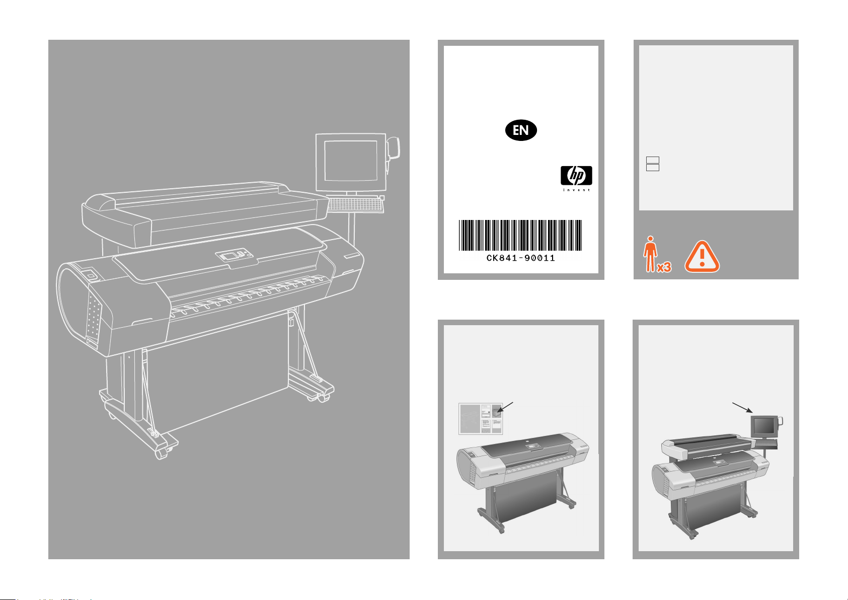
HP Designjet
T11XX (HD) MFP
Assembly Instructions
© 2008 Hewlett-Packard Company
Inkjet Commercial Division
Avenida Graells 501 · 08174
Sant Cugat del Vallès
Barcelona · Spain
All rights reserved
Printed in Germany Imprimé en Allemagne Stampato in Germania
Read these instructions carefully...
What you will need for this procedure
• Because the scanner is heavy, you may
need three people to unpack it. When
more than one person is needed, the symbol
at the foot of this box is displayed.
• During the stand assembly you will see
some reference to the following symbol
labels which appear on some items, standing for left side, and right side.
L Left side
R Right side
Your printer should already be assembled
and working before starting this procedure.
For instructions on how to assemble the
printer, please refer to the assembly poster
included with the printer.
Assembly poster
The touch screen assembly can be mounted
on either the right or the left side of the
stand.
Touch screen assembly
Page 2
Attach the lower bar to the two legs. Tighten
1
the screws with the T-handle torx driver T30
found in the assembly kit.
Unpacking stand
Turn the legs upside down, and attach the
Turn the legs upside down, and attach the
7
2
two feet to the left and right legs using four
two feet to the left and right legs.
M6×30 screws (two for each foot). Tighten
the screws with the T-handle Torx driver
T30 found in the assembly kit.
Attach the bottom bar to the legs.
3 54
Carefully raise the legs into the upright
position.
Stand assembly
M6×10
Fasten the top bar and wire guide to the
two legs using four screws and the two
limit stops.
M6×30
M6×10
M6×30
Page 3
Turn the legs upside down, and attach the
Tighten up all screws rmly.
7
6
two feet to the left and right legs using four
M6×30 screws (two for each foot). Tighten
the screws with the T-handle Torx driver
T30 found in the assembly kit.
Turn the legs upside down, and attach the
Using three people; two to lift, and one to
7
10
two feet to the left and right legs using four
position, lift the scanner into place locating
M6×30 screws (two for each foot). Tighten
the rubber feet in the holes indicated.
the screws with the T-handle Torx driver
T30 found in the assembly kit.
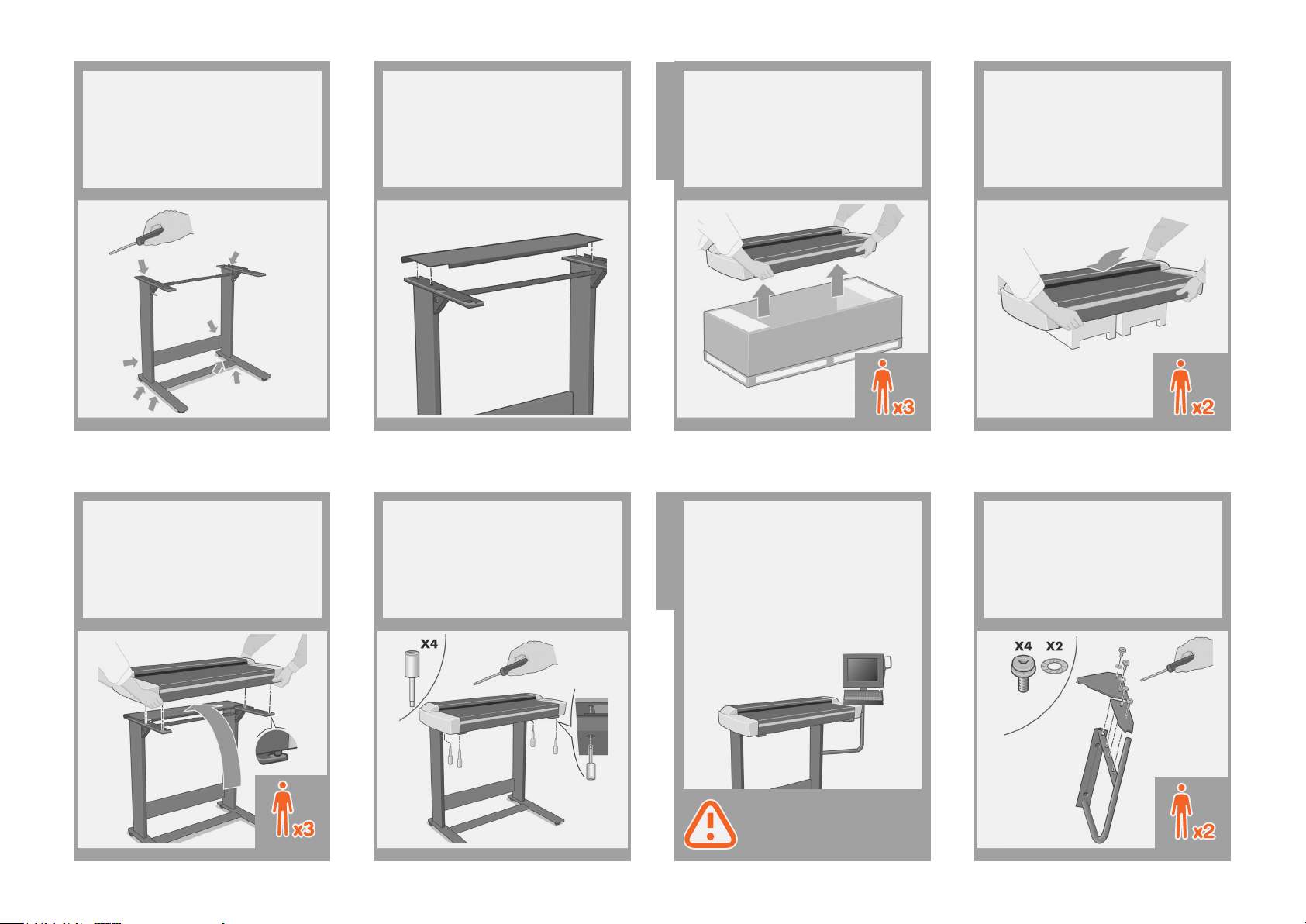
Connect the rear table. This is tted by
7 9
locating the four guide pins on the rear of
the table into the rubber-framed holes on the
top bar.
Fix with the four special screws using the
11 12
T-handle hex driver 2.5mm.
Using two people, remove the scanner from
8
the box. The third person should place some
packaging boxes (we recommend the foam
end packs from the scanner box) on the
oor.
Attach scanner
to stand
At this point you must decide on which side you
are going to t the touch screen assembly. This
can be tted on the left or right side of the stand.
The next steps, 12 to 22, explain how to t
the touch screen assembly to the right side of the
stand.
Touch screen
assembly
To t the touch screen assembly to the left side
of the stand, using the same parts, just ‘mirror’
the assembly procedure described here.
Place the scanner onto the packaging
boxes.
Attach the two bracket covers to the
touch screen bracket using two screws
on the straight bracket cover and two
screws and two starwashers on the
triangular bracket cover.
M5X14
Page 4

Attach two (M6X10) screws to the leg, and
13
two (M5X14) screws with two starwashers;
one on the leg and one on the top bar
triangular brace piece where shown. Don’t
tighten them fully; leave a 4mm gap.
M6X10 M5X14
Slide the touch screen bracket into place
14
over the four screws.
Tighten the four screws.
15
Slide the keyboard table onto the touch
16
screen arm.
Push the keyboard table down until the
17
pointer slots into place on the touch screen
arm.
With the protective foam in place, put the
18
touch screen face down and attach the
monitor joint to the rear along with one
end of the earth cable where shown, using
four M5×14 screws and one star washer
for the earth cable.
M5×14
Remove the protective foam ends, and
19
slide the hub of the touch screen assembly
into the touch screen arm.
Connect the earth cable from the touch
20
screen assembly to the touch screen arm
using a screw and starwasher.
M5X14
Page 5

Push the keyboard table down until the
21
pointer slots into place on the touch screen
arm.
Fix the touch screen pen to the side of the
22
touch screen.
The unit is now assembled and should appear
as in the below illustration.
Open the scanner corner cover.
23
Remove the foam retainer from inside the
24
scanner.
Close the scanner corner cover.
25
Slide the assembled printer under the
26
scanner. The printer’s feet will be positioned outside the scanner’s feet.
27
Cabling and
connecting
Cable
through
holes.
Connect the keyboard to the touch screen,
passing the cable along the inside of the
arm and up through the hole in the
keyboard bracket as shown.
Page 6

Connect the cable bundle to the touch
28
screen as shown (passing it between
the bracket and the scanner); inserting
the Power, USB, FireWire, and Network
connections.
Power
Network
USB &
Firewire
Remove the cover on the side of the scan-
29
ner, and insert one of the FireWire cables
through the slot at the back.
Fit the protected part of the bundle cable
30
coming from the screen into four large
clips. Attach the clips to the holes in the
touch screen bracket covers.
Remove the scanner’s back cover, and
31
place any excess cable in the space
shown below. Replace the cover.
Connect the power cable to the scanner.
32
Fit the ‘Y’ power cable into the clips. Then
33
attach the clips to the stand.
If the touch screen assembly has been
mounted on the left leg, the ‘Y’ power
cable should only be attached to the left
leg and cross bar.
Conect the scanner to the printer with
34
the USB cable. Adjust the cable to leave
enough slack to be able to pull out the
printer when changing paper.
Page 7

Connect the ‘Y’ power cable to a power
35
outlet.
If you have not done so already, connect
36
the printer to a power outlet and switch
it on.
You are now required to clean the scan
area. To do so you will need the cleaning
tools provided in the maintenance kit
and a cleaning uid (not included in the
maintenance kit).
Caution: do not use abrasives, acetone,
Cleaning the scan area
benzene, or uids that contain these
chemicals. Do not spray liquids directly
onto the scanner glass plate or anywhere
else in the scanner.
Push down the two locks, and open the
37
scanner cover to expose the scan area.
Clean the glass with a lint-free cloth and
38
a mild, streak-free, glass cleaner.
Dry the glass fully using a separate clean,
39
dry lint-free cloth like the one provided
with the maintenance kit.
Clean the white background plate with a
40
lint-free cloth and a mild, streak-free, glass
cleaner.
Clean the transport rollers and
41
surrounding area.
Page 8

Dry the white background plate, rollers,
42
and surrounding area fully using a separate clean, dry lint-free cloth.
Close the scanner cover and push down
43
on the top to lock it into place.
Switch on the scanner and leave it to
44
warm up until the orange light goes
off, and the green (ready status) light
appears.
When the green (ready status) light has
45
appeared, switch on the touch screen.
To initialise: choose your language
46
(below), read the license agreement,
press I Agree, and hide the getting
started window.
Note: if when switching on the touch
screen a No scanner was found message
appears, please press the Rescan
option on the touch screen.
You are now required to calibrate the
scanner. For this you will need the
scanner maintenance sheet, found in the
protective folder shown below.
Alignment and
calibration
Important: when setting up for the rst
time, make sure that the scanner is turned
on for at least one hour before moving
on to the next step of camera alignment
calibration. Slight light intensity changes
and camera shifting can occur just after
turning the scanner on, and warm-up
time will ensure that light conditions and
camera heights have stabilized.
Page 9

To start the maintenance procedure:
1: On the touch screen, press the
setup tab.
2: Press Options button and select
Scanning.
3: Press Scanner Maintenance Button.
The maintenance wizard will ask you to
47
insert the maintenance sheet. The sheet’s
printed side must be face down. Feed
the paper in aligning the two midpoint
arrows. Press Next to continue. Note: if
already installed, make sure you remove
the magnetic media guides for this part of
the process.
Remove the magnetic
media guides
Now follow the instructions that appear
48
on the touch screen.
Next, you should check the TCP/IP
49
settings in your touch screen (go to:
Setup/Option/System/Advanced/Network settings/IP Address), and correct
them if necessary.
Connecting to the
printer
If you intend to scan to the network, with
the HP Designjet scan software, les to
be shared across the network should be
placed in the D:\images directory.
Once a le is saved to this directory it
can be accessed through the network,
from any computer with any operating
system.
For more guidance on this issue, see the
user documentation that came with your
unit.
To add an HP Designjet printer to the
printer list in your scanner software, follow
these steps:
1: On the touch screen go to the setup tab.
2: Press option button and select system.
3: Press Install Printer Driver.
4: Press the button for the printer you wish
to install.
5: Follow the instructions on the screen.
Next, you should generate a media pro-
50
le: rst you press button media prole,
then you press installed paper, where
asked: No media prole exists, click OK.
Media prole
generation
Keep out dust and reduce maintenance
time: when not in use, cover your scanner
with the plastic dust cover.
Notes and advice
Caution: make sure the scanner power is
OFF when using the scanner dust cover.
When the maintenance procedure has
completed, remove the scanner maintenance sheet and return it to its protective
cover.
Page 10

Your HP Designjet comes equipped with
two magnetic media guides; these can be
placed and moved as required.
The scanner’s ruler can be changed between centimeters and inches by sliding it
out, turning it over, and reinserting it.
For any further information on how to use
your scanner, see the online help system
available from your touch screen using
the button below.
Keep these instructions
In order to perform routine maintenance
(once a month) you will nd it useful to
refer again to the following sections:
• cleaning the scan area
• Alignment and calibration
 Loading...