


 Loading...
HP Notebook PC (AMD)
*Models: 14-an0XX
*Models: 14-as0XX
*Models: 14-au0XX
*Models: 14z-an000
HP 245 G5 Notebook PC
Maintenance and Service Guide
© Copyright 2016 HP Development Company,
L.P.
AMD is a trademark of Advanced Micro Devices, Inc. Bluetooth is a trademark owned by its proprietor and used by HP Inc. under license. Intel is a trademark of Intel Corporation in the U.S. and other countries. Microsoft and Windows are U.S. registered trademarks of the Microsoft group of companies.
The information contained herein is subject to change without notice. The only warranties for HP products and services are set forth in the express warranty statements accompanying such products and services. Nothing herein should be construed as constituting an additional warranty. HP shall not be liable for technical or editorial errors or omissions contained herein.
Second Edition: August 2016
First Edition: April 2016
Document Part Number: 855442-002
Product notice
This guide describes features that are common to most models. Some features may not be available on your computer.
Not all features are available in all editions of Windows. This computer may require upgraded and/or separately purchased hardware, drivers, and/or software to take full advantage of Windows functionality. See http://www.microsoft.com for details.
Software terms
By installing, copying, downloading, or otherwise using any software product preinstalled on this computer, you agree to be bound by the terms of the HP End User License Agreement (EULA). If you do not accept these license terms, your sole remedy is to return the entire unused product (hardware and software) within 14 days for a refund subject to the refund policy of your place of purchase.
For any further information or to request a full refund of the computer, please contact your local point of sale (the seller).

Safety warning notice
 WARNING! To reduce the possibility of heat-related injuries or of overheating the device, do not place the device directly on your lap or obstruct the device air vents. Use the device only on a hard, flat surface. Do not allow another hard surface, such as an adjoining optional printer, or a soft surface, such as pillows or rugs or clothing, to block airflow. Also, do not allow the AC adapter to contact the skin or a soft surface, such as pillows or rugs or clothing, during operation. The device and the AC adapter comply with the user-accessible surface temperature limits de ned by the International Standard for Safety of Information Technology Equipment (IEC 60950-1).
iii
iv Safety warning notice

Table of contents
1 Product description ....................................................................................................................................... |
1 |
2 External component dent cat on .................................................................................................................. |
5 |
Display .................................................................................................................................................................... |
5 |
Right side ............................................................................................................................................................... |
6 |
Left side ................................................................................................................................................................. |
7 |
Top .......................................................................................................................................................................... |
8 |
TouchPad ............................................................................................................................................. |
8 |
Lights ................................................................................................................................................... |
9 |
Button ................................................................................................................................................ |
10 |
Keys ................................................................................................................................................... |
11 |
Bottom ................................................................................................................................................................. |
12 |
Service tag ........................................................................................................................................................... |
13 |
3 Illustrated parts catalog .............................................................................................................................. |
15 |
Computer major components .............................................................................................................................. |
15 |
Miscellaneous parts ............................................................................................................................................. |
18 |
Display assembly subcomponents ...................................................................................................................... |
19 |
Mass storage devices ........................................................................................................................................... |
20 |
4 Removal and replacement procedures preliminary requirements .................................................................... |
21 |
Tools required ...................................................................................................................................................... |
21 |
Service considerations ......................................................................................................................................... |
21 |
Plastic parts ....................................................................................................................................... |
21 |
Cables and connectors ...................................................................................................................... |
21 |
Drive handling ................................................................................................................................... |
22 |
Grounding guidelines ........................................................................................................................................... |
22 |
Electrostatic discharge damage ........................................................................................................ |
22 |
Packaging and transporting guidelines .......................................................................... |
23 |
Workstation guidelines ................................................................................ |
23 |
5 Removal and replacement procedures for Customer Self-Repair parts ............................................................. |
25 |
Component replacement procedures .................................................................................................................. |
25 |
Battery ............................................................................................................................................... |
26 |
Optical drive ....................................................................................................................................... |
27 |
v
6 Removal and replacement procedures for Authorized Service Provider parts ................................................... |
29 |
Component replacement procedures .................................................................................................................. |
29 |
Bottom cover ..................................................................................................................................... |
30 |
Hard drive .......................................................................................................................................... |
32 |
eMMC module .................................................................................................................................... |
34 |
WLAN module .................................................................................................................................... |
36 |
Memory module ................................................................................................................................ |
38 |
RTC battery ........................................................................................................................................ |
39 |
USB board .......................................................................................................................................... |
40 |
Speakers ............................................................................................................................................ |
41 |
Power button board .......................................................................................................................... |
42 |
Heat sink assembly ........................................................................................................................... |
43 |
Fan ..................................................................................................................................................... |
46 |
System board .................................................................................................................................... |
48 |
TouchPad button board ..................................................................................................................... |
52 |
Display assembly ............................................................................................................................... |
53 |
Power connector cable ...................................................................................................................... |
61 |
Top cover/keyboard ........................................................................................................................... |
62 |
7 Using Setup Utility (BIOS) in Windows 10 ....................................................................................................... |
63 |
Starting Setup Utility (BIOS) ................................................................................................................................ |
63 |
Updating Setup Utility (BIOS) .............................................................................................................................. |
63 |
Determining the BIOS version ........................................................................................................... |
63 |
Downloading a BIOS update .............................................................................................................. |
64 |
8 Backing up, restoring, and recovering in Windows 10 ..................................................................................... |
65 |
Creating recovery media and backups ................................................................................................................ |
65 |
Creating HP Recovery media (select products only) ......................................................................... |
65 |
Using Windows tools ........................................................................................................................................... |
66 |
Restore and recovery ........................................................................................................................................... |
67 |
Recovering using HP Recovery Manager ........................................................................................... |
67 |
What you need to know before you get started ............................................................. |
67 |
Using the HP Recovery partition (select products only) ................................................. |
68 |
Using HP Recovery media to recover .............................................................................. |
68 |
Changing the computer boot order ................................................................................ |
69 |
Removing the HP Recovery partition (select products only) ......................................... |
69 |
9 Using HP PC Hardware Diagnostics (UEFI) ....................................................................................................... |
71 |
Downloading HP PC Hardware Diagnostics (UEFI) to a USB device .................................................................... |
71 |
vi
10 |
pec cat ons ............................................................................................................................................ |
73 |
|
Computer speci cations ...................................................................................................................................... |
73 |
|
35.6-cm (14.0-in) display speci cations ............................................................................................................. |
74 |
|
Hard drive speci cations ..................................................................................................................................... |
75 |
|
DVD±RW SuperMulti DL Drive speci cations ....................................................................................................... |
76 |
11 |
Statement of memory volatility .................................................................................................................. |
77 |
|
Nonvolatile memory usage ................................................................................................................................. |
81 |
|
Questions and answers ....................................................................................................................................... |
83 |
|
Using HP Sure Start (select models only) ............................................................................................................ |
84 |
12 |
Power cord set requirements ...................................................................................................................... |
85 |
|
Requirements for all countries ............................................................................................................................ |
85 |
|
Requirements for speci c countries and regions ................................................................................................ |
86 |
13 |
Recycling .................................................................................................................................................. |
89 |
Index ............................................................................................................................................................. |
91 |
|
vii
viii

1Product description
Category |
Description |
Discrete |
UMA |
UMA, on- |
UMA, on- |
HP 245 |
|
|
graphics |
graphics |
board mem, |
board |
G5 |
|
|
|
|
eMMC |
mem |
|
|
|
|
|
|
|
|
Product |
HP Notebook PC |
√ |
√ |
√ |
√ |
|
name |
Model numbers: 14-an0XX, 14-as0XX, 14-au0XX, 14z- |
|
|
|
|
|
|
|
|
|
|
|
|
|
an000 |
|
|
|
|
|
|
|
|
|
|
|
|
|
HP 245 G5 Notebook PC |
|
|
|
|
√ |
|
|
|
|
|
|
|
Processor |
AMD Quad-Core A-Series Processor |
√ |
√ |
|
|
√ |
|
A8-7410 (2.2 GHz, turbo up to 2.5 GHz), 1600 MHz/2 |
|
|
|
|
|
|
MB L2, Quad 15W |
|
|
|
|
|
|
|
|
|
|
|
|
|
A6-7310 (2.0 GHz, turbo up to 2.4 GHz), 1600 MHz/2 |
√ |
√ |
|
|
√ |
|
MB L2, Quad 15W |
|
|
|
|
|
|
|
|
|
|
|
|
|
A4-7210 (1.8 GHz, turbo up to 2.2 GHz), 1600 MHz/2 |
|
√ |
|
|
|
|
MB L2, Quad 15W |
|
|
|
|
|
|
|
|
|
|
|
|
|
A4-3350B (2.0 GHz, turbo up to 2.4 GHz), 1600 MHz/2 |
|
|
|
|
√ |
|
MB L2, Quad 15W |
|
|
|
|
|
|
|
|
|
|
|
|
|
AMD Quad-Core E-Series Processor |
|
√ |
√ |
√ |
√ |
|
E2-7110 (1.8 GHz), 1600 MHz/2 MB L2, Quad 15W |
|
|
|
|
|
|
|
|
|
|
|
|
Chipset |
Integrated SoC FCH |
√ |
√ |
√ |
√ |
√ |
|
|
|
|
|
|
|
Graphics |
Internal graphics |
√ |
|
|
|
√ |
|
AMD Radeon™ R5 Graphics (A8 processor) |
|
|
|
|
|
|
|
|
|
|
|
|
|
AMD Radeon R4 Graphics (A6 processor) |
√ |
|
|
|
√ |
|
|
|
|
|
|
|
|
AMD Radeon R3 Graphics (A4 processor) |
|
√ |
√ |
√ |
|
|
|
|
|
|
|
|
|
AMD Radeon R2 Graphics (E1/E2 processor) |
|
√ |
√ |
√ |
√ |
|
|
|
|
|
|
|
|
Switchable discrete graphics |
√ |
|
|
|
|
|
AMD Radeon R5 M430 R16M-M1-30 (Exo Pro DDR3) |
|
|
|
|
|
|
with up to 2048MB of dedicated video memory |
|
|
|
|
|
|
|
|
|
|
|
|
|
Supports HD Decode, DX12, HDMI |
√ |
√ |
√ |
√ |
|
|
|
|
|
|
|
|
|
Supports PX7 |
√ |
|
|
|
|
|
|
|
|
|
|
|
Panel |
35.6-cm (14.0-in), white light-emitting diode (WLED), |
√ |
√ |
√ |
√ |
√ |
|
BrightView (1366×768) display, slim-flat 3.0 mm, eDP; |
|
|
|
|
|
|
typical brightness: 220 nits: |
|
|
|
|
|
|
|
|
|
|
|
|
|
HD, SVA |
√ |
√ |
√ |
√ |
√ |
|
|
|
|
|
|
|
|
FHD, UWVA |
|
√ |
|
|
|
|
|
|
|
|
|
|
Memory |
Two non-customer-accessible/upgradable memory |
√ |
√ |
|
|
√ |
|
module slots |
|
|
|
|
|
|
DDR3L-1600 Single Channel Support |
|
|
|
|
|
1

Category |
Description |
|
Discrete |
UMA |
UMA, on- |
UMA, on- |
HP 245 |
|
|
|
graphics |
graphics |
board mem, |
board |
G5 |
|
|
|
|
|
eMMC |
mem |
|
|
|
|
|
|
|
|
|
|
Supports up to 16 GB of system RAM in the following |
|
|
|
|
|
|
|
con gurations |
|
|
|
|
|
|
|
● 8192-MB total system memory (8192×1) or |
|
|
|
|
|
|
|
(4096×2) |
|
|
|
|
|
|
|
● 6144-MB total system memory (4096×1) |
|
|
|
|
|
|
|
+ (2048×1) |
|
|
|
|
|
|
|
● 4096-MB total system memory (4096×1) or |
|
|
|
|
|
|
|
(2048×2) |
|
|
|
|
|
|
|
● 2048-MB total system memory (2048×1) |
|
|
|
|
|
|
|
|
|
|
|
|
|
|
|
● 16384-MB total system memory (8192×2) |
√ |
|
|
|
√ |
|
|
|
|
|
|
|
|
|
|
On-board system memory |
|
|
√ |
√ |
|
|
|
DDR3L-1600 single channel support |
|
|
|
|
|
|
|
Supports up to 2 GB max on-board system memory |
|
|
|
|
|
|
|
|
|
|
|
|
|
|
Hard drives |
Single hard drive con urat ons |
√ |
√ |
√ |
√ |
√ |
|
|
Supports 6.35-cm (2.5-in) SATA hard drives in 9.5-mm |
|
|
|
|
|
|
|
(.37-in) and 7.0-mm (.28-in) thicknesses |
|
|
|
|
|
|
|
● 2-TB, 5400-rpm, 9.5-mm |
|
|
|
|
|
|
|
● 1-TB, 5400-rpm, 9.5-mm |
|
|
|
|
|
|
|
● 500-GB, 5400-rpm, 9.5-mm or 7.2-mm |
|
|
|
|
|
|
|
|
|
|
|
|
|
|
|
● 500-GB, 7200-rpm, 7.0-mm |
|
|
|
|
√ |
|
|
|
|
|
|
|
|
|
|
SSHD con |
urat ons |
|
√ |
|
|
|
|
500 GB, 5400 RPM, 7 mm, SSHD w/8GB NAND |
|
|
|
|
|
|
|
|
|
|
|
|
|
|
|
eMMC con |
urat ons |
|
√ |
√ |
|
|
|
32 GB |
|
|
|
|
|
|
|
|
|
|
|
|
|
|
|
64 GB |
|
|
√ |
|
|
|
|
|
|
|
|
|
|
|
Optical drive |
Fixed, serial ATA, 9.5-mm tray load |
√ |
√ |
√ |
√ |
√ |
|
|
Supports con guration without optical drive |
|
|
|
|
|
|
|
|
|
|
|
|
|
|
|
DVD+/-RW Double-Layer SuperMulti |
√ |
√ |
|
√ |
√ |
|
|
Supports zero power optical drive |
|
|
|
|
|
|
|
Supports M-disc |
|
|
|
|
|
|
|
|
|
|
|
|
|
|
Webcam/mic |
HP TrueVision HD: HD camera - activity LED, USB 2.0, |
√ |
√ |
√ |
√ |
√ |
|
|
BSI sensor, 1280 x 720 by 30 frames per second |
|
|
|
|
|
|
|
HP Webcam– 640 x 480 by 24 frames per second |
|
|
|
|
|
|
|
Single digital microphone |
|
|
|
|
|
|
|
HP Noise Cancellation enabled |
|
|
|
|
|
|
|
|
|
|
|
|
|
|
Audio |
DTS Studio Sound |
√ |
√ |
√ |
√ |
√ |
|
|
Dual speakers |
|
|
|
|
|
|
|
|
|
|
|
|
|
|
2Chapter 1 Product description
Category |
Description |
Discrete |
UMA |
UMA, on- |
UMA, on- |
HP 245 |
|
|
|
|
graphics |
graphics |
board mem, |
board |
G5 |
|
|
|
|
|
eMMC |
mem |
|
|
|
|
|
|
|
|
|
Ethernet |
Integrated 10/100 network interface card (NIC) |
√ |
√ |
√ |
√ |
|
|
|
|
|
|
|
|
|
|
Wireless |
Integrated wireless options with single antenna (M. |
√ |
√ |
√ |
√ |
√ |
|
Network |
2/PCIe): |
|
|
|
|
|
|
|
Compatible with iracast-certi ed devices |
|
|
|
|
|
|
|
Support for the following WLAN formats: |
|
|
|
|
|
|
|
● |
Intel Dual Band Wireless-AC 3165 802.11 ac 1x1 |
|
|
|
|
|
|
|
WiFi + BT 4.2 Combo Adapter |
|
|
|
|
|
|
● |
Intel Dual Band Wireless-AC 3168 802.11 ac 1x1 |
|
|
|
|
|
|
|
WiFi + BT 4.2 Combo Adapter |
|
|
|
|
|
|
● |
Realtek RTL8188EE-VJ 802.11b/g/n 1x1 Wi-Fi |
|
|
|
|
|
|
|
Adapter |
|
|
|
|
|
|
● |
Realtek RTL8188EE 802.11b/g/n 1x1 Wi-Fi |
|
|
|
|
|
|
|
Adapter |
|
|
|
|
|
|
● |
Realtek RTL8723BE-VB 802.11b/g/n 1x1 Wi-Fi + |
|
|
|
|
|
|
|
BT4.0 Combo Adapter (HP Notebook PC models |
|
|
|
|
|
|
|
only) |
|
|
|
|
|
|
|
|
|
|
|
|
|
External |
HP Multi-Format Digital Media Reader |
√ |
√ |
√ |
√ |
√ |
|
media card |
Support SD/SDHC/SDXC |
|
|
|
|
|
|
|
|
|
|
|
|
||
|
Push-Pull Insertion/Removal |
|
|
|
|
|
|
|
|
|
|
|
|
|
|
Internal Card |
One M.2 slot for WLAN |
√ |
√ |
√ |
√ |
√ |
|
|
|
|
|
|
|
|
|
Ports |
VGA (Dsub 15 pin) supporting: 1920 × 1200 external |
√ |
√ |
√ |
√ |
√ |
|
|
resolution @ 60Hz. Hot Plug/unplug and auto detect for |
|
|
|
|
|
|
|
correct output to wide-aspect vs. standard aspect |
|
|
|
|
|
|
|
video. |
|
|
|
|
|
|
|
HDMI version 1.4b supporting 1920 ×1080 @ 60Hz |
|
|
|
|
|
|
|
RJ-45 (Ethernet) |
|
|
|
|
|
|
|
USB 3.0 (1 port; left side) |
|
|
|
|
|
|
|
USB 2.0 (2 ports; 1 left side, 1 right side) |
|
|
|
|
|
|
|
AC Smart Pin adapter plug |
|
|
|
|
|
|
|
Headphone/line out and microphone/line in combo jack |
|
|
|
|
|
|
|
|
|
|
|
|
|
|
Keyboard/ |
Full-size textured "island style" keyboard with numeric |
√ |
√ |
√ |
√ |
√ |
|
pointing |
keypad |
|
|
|
|
|
|
devices |
TouchPad with multi-touch gestures enabled |
|
|
|
|
|
|
|
|
|
|
|
|
||
|
Taps enabled by default |
|
|
|
|
|
|
|
Support Modern Trackpad Gestures |
|
|
|
|
|
|
|
|
|
|
|
|
|
|
Power |
AC adapters |
√ |
|
|
|
√ |
|
|
65-W |
|
|
|
|
|
|
|
|
|
|
|
|
|
|
|
65-W EM |
√ |
|
|
|
|
|
|
|
|
|
|
|
|
|
|
45-W |
|
|
√ |
√ |
√ |
√ |
|
45-W EM |
|
|
|
|
|
|
|
|
|
|
|
|
|
|
3

Category |
Description |
Discrete |
UMA |
UMA, on- |
UMA, on- |
HP 245 |
|
|
graphics |
graphics |
board mem, |
board |
G5 |
|
|
|
|
eMMC |
mem |
|
|
|
|
|
|
|
|
|
1 meter power cord |
√ |
√ |
√ |
√ |
√ |
|
|
|
|
|
|
|
|
Batteries |
√ |
√ |
√ |
√ |
√ |
|
4-cell, 41-Whr Li-ion battery |
|
|
|
|
|
|
|
|
|
|
|
|
|
3-cell, 31-Whr Li-ion battery |
|
√ |
√ |
√ |
√ |
|
|
|
|
|
|
|
|
6-cell, 47-Whr Li-ion battery |
|
|
|
|
√ |
|
|
|
|
|
|
|
Security |
TPM 2.0 |
√ |
√ |
√ |
√ |
√ |
|
Kensington Security Lock |
|
|
|
|
|
|
|
|
|
|
|
|
Operating |
Preinstalled |
√ |
√ |
|
|
√ |
system |
Windows 10 |
|
|
|
|
|
|
|
|
|
|
|
|
|
Windows 10 Professional |
|
|
|
|
|
|
Windows 10 Home ML |
|
|
|
|
|
|
|
|
|
|
|
|
|
Windows 10 Home Value Notebook |
|
|
|
√ |
|
|
|
|
|
|
|
|
|
Windows 10 Home Entry NB |
|
√ |
√ |
|
|
|
Windows 10 Home Entry NB EM/SL |
|
|
|
|
|
|
Windows 10 Home Entry NB w/OneDrive |
|
|
|
|
|
|
Windows 10 Home Entry NB w/OneDrive EM/SL |
|
|
|
|
|
|
|
|
|
|
|
|
|
Windows 10 Home EM/SL |
√ |
√ |
√ |
|
|
|
Windows 10 Home High End ML |
|
|
|
|
|
|
|
|
|
|
|
|
|
Windows 10 Home EM/SL |
√ |
√ |
|
|
|
|
|
|
|
|
|
|
|
Windows 10 Home Value Notebook EM/SL |
|
|
|
√ |
|
|
|
|
|
|
|
|
|
CPPP Windows 10 Home China/SL 64 |
√ |
√ |
|
|
|
|
CPPP Windows 10 Home EM/SL 64 SEAP |
|
|
|
|
|
|
|
|
|
|
|
|
|
Windows 10 Home Value Notebook EM/SL 64 SEAP NB |
√ |
√ |
|
√ |
|
|
|
|
|
|
|
|
|
Windows 10 Home Value India EM/SL 64 NB |
|
|
|
√ |
|
|
|
|
|
|
|
|
|
Windows 10 Professional Shape the Future MSNA (EM) |
|
|
|
|
√ |
|
Windows 10 Pro Downgrade to Windows 7 Pro |
|
|
|
|
|
|
Windows 10 Pro Downgrade to Windows 7 Pro StF |
|
|
|
|
|
|
MSNA |
|
|
|
|
|
|
|
|
|
|
|
|
|
Windows 10 Home MSNA (EM) |
|
|
|
|
√ |
|
|
|
|
|
|
|
|
FreeDOS 2.0 |
√ |
√ |
√ |
√ |
√ |
|
|
|
|
|
|
|
Service |
End-user replaceable parts |
√ |
√ |
√ |
√ |
√ |
|
AC adapter |
|
|
|
|
|
|
Battery |
|
|
|
|
|
|
Optical drive |
|
|
|
|
|
|
|
|
|
|
|
|
4Chapter 1 Product description
2 External component dent cat on
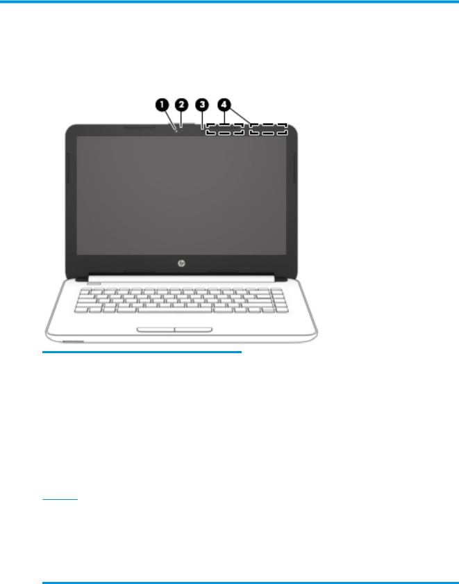
Display
Component |
Description |
|
|
|
|
(1) |
Webcam light |
On: The webcam is in use. |
|
|
|
(2) |
Webcam |
Records video and captures photographs. Some products allow you |
|
|
to video conference and chat online using streaming video. |
|
|
To use a webcam (integrated camera): |
|
|
▲ Type camera in the taskbar search box, and then select |
|
|
Camera. |
|
|
|
(3) |
Internal microphone |
Records sound. |
|
|
|
(4) |
WLAN antennas* |
Send and receive wireless signals to communicate with wireless local |
|
|
area networks (WLANs). |
*The antennas are not visible from the outside of the computer. For optimal transmission, keep the areas immediately around the antennas free from obstructions.
For wireless regulatory notices, see the section of the Regulatory, Safety, and Environmental Notices that applies to your country or region.
To access this guide:
▲Select the Start button, select All apps, select HP Help and Support, and then select HP Documentation.
Display 5
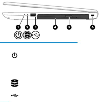
Right side
Component |
|
Description |
|
|
|
|
|
(1) |
Power light |
● |
On: The computer is on. |
|
|
● |
Blinking: The computer is in the Sleep state, a power- |
|
|
|
saving state. The computer shuts o power to the display |
|
|
|
and other unneeded components. |
|
|
● |
The computer is o or in Hibernation. Hibernation is a |
|
|
|
power-saving state that uses the least amount of power. |
|
|
|
|
(2) |
Drive light (select products only) |
● |
Blinking white: The hard drive is being accessed. |
|
|
|
|
(3) |
USB 2.0 port |
Connects an optional USB device, such as a keyboard, mouse, |
|
|
|
external drive, printer, scanner or USB hub. |
|
(4)Optical drive (select products only)
Depending on your computer, reads an optical disc or reads and writes to an optical disc.
|
|
NOTE: For disc compatibility information, type help in the |
|
|
taskbar search box, select Help and Support, and then type |
|
|
disc compatibility in the search box. |
|
|
|
(5) |
Optical drive eject button (select products only) |
Releases the optical drive disc tray. |
|
|
|
(6) |
Security cable slot |
Attaches an optional security cable to the computer. |
|
|
NOTE: The security cable is designed to act as a deterrent, but |
|
|
it may not prevent the computer from being mishandled or |
|
|
stolen. |
|
|
|
6 Chapter 2 External component identi cation
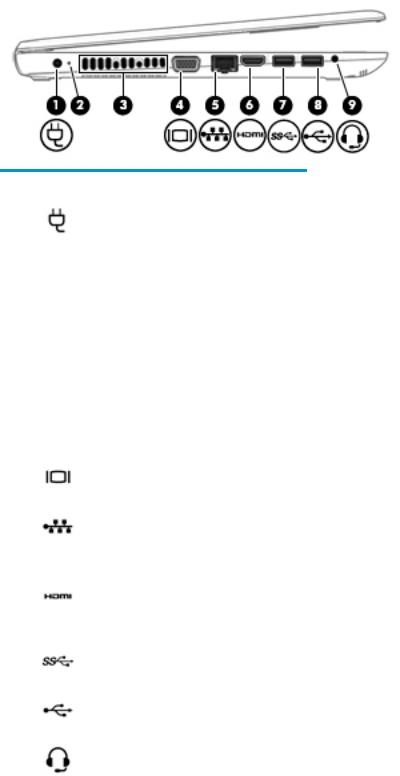
Left side
Component |
|
Description |
|
|
|
|
|
(1) |
Power connector |
Connects an AC adapter. |
|
|
|
|
|
(2) |
AC adapter and battery light |
● |
White: The AC adapter is connected and the battery is fully |
|
|
|
charged. |
|
|
● |
Blinking white: The AC adapter is disconnected and the |
|
|
|
battery has reached a low battery level. |
|
|
● |
Amber: The AC adapter is connected and the battery is |
|
|
|
charging. |
|
|
● |
The battery is not charging. |
|
|
|
|
(3) |
Vent |
Enables airflow to cool internal components. |
|
|
|
NOTE: The computer fan starts up automatically to cool |
|
|
|
internal components and prevent overheating. It is normal for |
|
|
|
the internal fan to cycle on and o during routine operation. |
|
|
|
|
|
(4) |
External monitor port |
Connects an external VGA monitor or projector. |
|
|
|
|
|
(5) |
RJ-45 (network) jack/status lights |
Connects a network cable. |
|
|
|
● |
White: The network is connected. |
|
|
● |
Amber: Activity is occurring on the network. |
|
|
|
|
(6) |
HDMI port |
Connects an optional video or audio device, such as a high- |
|
|
|
de |
nition television, any compatible digital or audio component, |
|
|
or a high-speed igh-De nition Multimedia Interface (HDMI) |
|
|
|
device. |
|
|
|
|
|
(7) |
USB 3.0 port |
Connects an optional USB device, such as a keyboard, mouse, |
|
|
|
external drive, printer, scanner or USB hub. |
|
|
|
|
|
(8) |
USB 2.0 port |
Connects an optional USB device, such as a keyboard, mouse, |
|
|
|
external drive, printer, scanner or USB hub. |
|
|
|
|
|
(9) |
Audio-out (headphone)/Audio-in (microphone) |
Connects optional powered stereo speakers, headphones, |
|
|
combo jack |
earbuds, a headset, or a television audio cable. Also connects an |
|
|
|
optional headset microphone. This jack does not support |
|
|
|
optional standalone microphones. |
|
Left side |
7 |
Component |
Description |
WARNING! To reduce the risk of personal injury, adjust the volume before putting on headphones, earbuds, or a headset. For additional safety information, refer to the Regulatory, Safety, and Environmental Notices.
To access this guide:
▲ Select the Start button, select All apps, select HP Help and Support, and then select HP Documentation.
NOTE: When a device is connected to the jack, the computer speakers are disabled.
Top
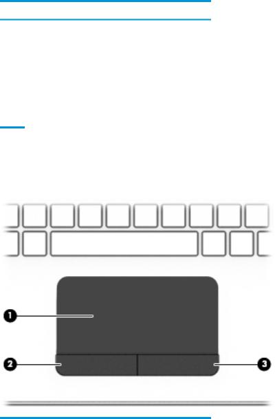
TouchPad
Component |
|
Description |
|
|
|
(1) |
TouchPad zone |
Reads your nger gestures to move the pointer or activate items |
|
|
on the screen. |
|
|
|
(2) |
Left TouchPad button |
Functions like the left button on an external mouse. |
|
|
|
(3) |
Right TouchPad button |
Functions like the right button on an external mouse. |
|
|
|
8 Chapter 2 External component identi cation
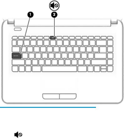
Lights
Component |
|
Description |
|
|
|
|
|
(1) |
Caps lock light |
On: Caps lock is on, which switches the key input to all capital |
|
|
|
letters. |
|
|
|
|
|
(2) |
Mute light |
● |
Amber: Computer sound is o . |
|
|
● |
Computer sound is on. |
|
|
|
|
Top 9
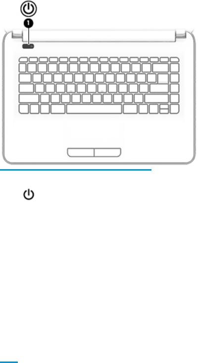
Button
Component |
|
Description |
|
|
|
|
|
(1) |
Power button |
● |
When the computer is o , press the button to turn on the |
|
|
|
computer. |
|
|
● |
When the computer is on, press the button briefly to |
|
|
|
initiate Sleep. |
|
|
● |
When the computer is in the Sleep state, press the button |
|
|
|
briefly to exit Sleep. |
|
|
● |
When the computer is in Hibernation, press the button |
|
|
|
briefly to exit Hibernation. |
|
|
CAUTION: Pressing and holding down the power button results |
|
|
|
in the loss of unsaved information. |
|
|
|
If the computer has stopped responding and shutdown |
|
|
|
procedures are ine ective, press and hold the power button |
|
|
|
down for at least 5 seconds to turn o the computer. |
|
|
|
To learn more about your power settings, see your power |
|
|
|
options. |
|
|
|
▲ |
Type power in the taskbar search box, and then select |
Power and sleep settings.
‒ or –
Right-click the Start button, and then select Power
Options.
10 Chapter 2 External component identi cation
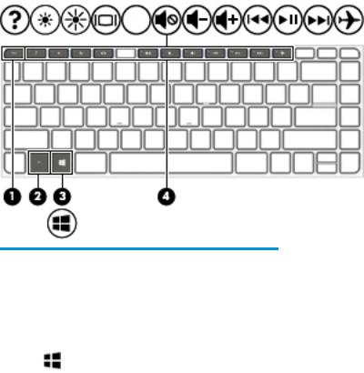
Keys
Component |
|
Description |
|
|
|
(1) |
esc key |
Displays system information when pressed in combination with |
|
|
the fn key. |
|
|
|
(2) |
fn key |
Executes frequently used system functions when pressed in |
|
|
combination with the esc key, action keys, or the spacebar. |
|
|
|
(3) |
Windows key |
Opens the Start menu. |
|
|
NOTE: Pressing the Windows key again will close the Start |
|
|
menu. |
|
|
|
(4) |
Action keys |
Execute frequently used system functions. |
|
|
|
Top 11
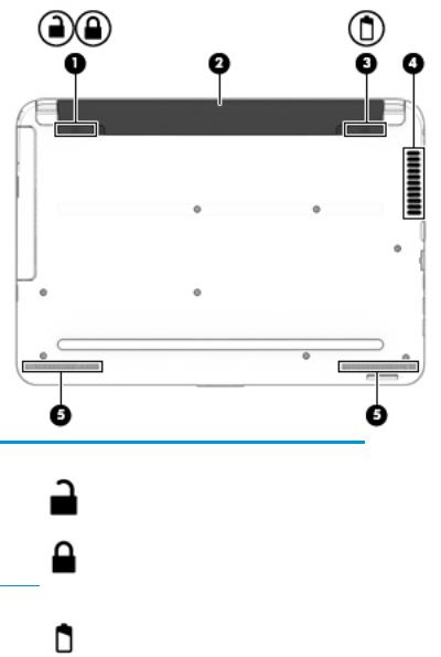
Bottom
Component |
|
Description |
|
|
|
(1) |
Battery lock |
Locks the battery in the battery bay. |
(2) |
Battery bay |
Holds the battery. |
|
|
|
(3) |
Battery release latch |
Releases the battery. |
|
|
|
(4) |
Vent |
Enables airflow to cool internal components. |
|
|
NOTE: The computer fan starts up automatically to cool |
|
|
internal components and prevent overheating. It is normal |
|
|
for the internal fan to cycle on and o during routine |
|
|
operation. |
|
|
|
(5) |
Speakers (2) |
Produce sound. |
|
|
|
12 Chapter 2 External component identi cation
Service tag
When ordering parts or requesting information, provide the computer serial number and model number provided on the service tag.
Item |
Description |
Function |
|
|
|
(1) |
Product name |
This is the product name affixed to the front of |
|
|
the computer. |
|
|
|
(2) |
Serial number (s/n) |
This is an alphanumeric identi er that is unique to |
|
|
each product. |
|
|
|
(3) |
Part number/Product number (p/n) |
This number provides speci c information about |
|
|
the product's hardware components. The part number helps |
|
|
a service technician to determine what components |
|
|
and parts are needed. |
|
|
|
(4) |
Warranty period |
This number describes the duration of the warranty period |
|
|
for the computer. |
|
|
|
(5) |
Model description |
This is the alphanumeric identi er used to locate |
|
|
documents, drivers, and support for the computer. |
|
|
|
Service tag 13
14 Chapter 2 External component identi cation

3Illustrated parts catalog
Computer major components
 NOTE: HP continually improves and changes product parts. For complete and current information on supported parts for your computer, go to http://partsurfer.hp.com, select your country or region, and then follow the on-screen instructions.
Computer major components 15

Item |
Component |
Spare part |
|
|
number |
|
|
|
(1) |
Display assembly (35.6-cm [14.0-in] HD, anti-glare, touchscreen) |
not spared |
|
NOTE: Full display hinge-ups are not spared. For display assembly subcomponent spare part |
|
|
information, see Display assembly subcomponents on page 19. |
|
(2)Top cover/keyboard (includes touchpad)
NOTE: For a list of country codes, see Top cover/keyboard on page 62.
For use only in HP Notebook PC models:
|
● |
Turbo silver |
858078-xx1 |
|
|
|
|
|
● |
White silver |
858079-xx1 |
|
|
|
|
|
● |
Red |
858080-xx1 |
|
|
|
|
|
● |
Blue |
858082-xx1 |
|
|
|
|
|
For use in all models: |
|
|
|
|
|
|
|
● |
Black |
858077-xx1 |
|
|
|
|
(3) |
Touchpad button board (includes cable) |
813517-001 |
|
|
|
|
|
(4) |
Speakers (left and right) |
858083-001 |
|
|
|
|
|
(5) |
Power button board (includes cable) |
813516-001 |
|
|
|
|
|
(6) |
Power connector cable |
813505-001 |
|
|
|
|
|
(7) |
System board (includes replacement thermal materials): |
|
|
|
All system boards use the following part numbers: |
|
|
|
xxxxxx-001: Windows 7 or non-Windows operating systems |
|
|
|
xxxxxx-601: Windows 10 operating system |
|
|
|
|
|
|
|
HP Notebook PC models with 2 GB of discrete graphics memory: |
|
|
|
|
|
|
|
● |
AMD A8-7410 processor |
858046-xx1 |
|
|
|
|
|
● |
AMD A6-7310 processor |
858045-xx1 |
|
|
|
|
|
HP Notebook PC models with UMA graphics memory: |
|
|
|
|
|
|
|
● |
AMD A8-7410 processor |
858044-xx1 |
|
|
|
|
|
● |
AMD A6-7310 processor |
858043-xx1 |
|
|
|
|
|
● |
AMD A4-7210 processor |
858042-xx1 |
|
|
|
|
|
● |
AMD E2-7110 processor |
858047-xx1 |
|
|
|
|
|
● |
AMD E2-7110 processor and 2 GB on-board system memory |
858048-xx1 |
|
|
|
|
|
● |
AMD E2-7110 processor, 2 GB on-board system memory, and a 32 GB eMMC drive |
858049-xx1 |
|
|
|
|
|
HP 245 G5 models: |
|
|
|
|
|
|
|
● |
AMD A8-7410 processor |
907163-xx1 |
|
|
|
|
|
● |
AMD A6-7310 processor |
860452-xx1 |
|
|
|
|
|
● |
AMD A4-3350B processor |
907162-xx1 |
|
|
|
|
16 Chapter 3 Illustrated parts catalog

Item |
Component |
Spare part |
|
|
|
|
number |
|
|
|
|
|
● |
AMD E2-7110 processor |
860451-xx1 |
|
|
|
|
(8) |
RTC battery |
718440-001 |
|
|
|
|
|
(9) |
Memory module (PC3L, 12800, 1600-MHz): |
|
|
|
|
|
|
|
8-GB |
|
693374-005 |
|
|
|
|
|
4 GB |
|
691740-005 |
|
|
|
|
|
2 GB |
|
691739-005 |
|
|
|
|
(10) |
USB board (includes cable) |
813515-001 |
|
|
|
|
|
|
Heat sink assembly (includes replacement thermal materials): |
|
|
|
|
|
|
(11) |
For use in models with UMA graphics memory |
813507-001 |
|
|
|
|
|
(12) |
For use in models with discrete graphics memory (HP Notebook PC models only) |
813508-001 |
|
|
|
|
|
(13) |
Fan |
|
813506-001 |
|
|
|
|
(14) |
WLAN module |
|
|
|
|
|
|
|
Realtek RTL8723BE-VB 802.11b/g/n 1x1 Wi-Fi + BT4.0 Combo Adapter |
855106-885 |
|
|
|
|
|
|
Intel Dual Band Wireless-AC 3165 802.11 ac 1x1 WiFi + BT 4.2 Combo |
806723-005 |
|
|
|
|
|
|
Realtek RTL8188EE-VJ 802.11b/g/n 1x1 Wi-Fi Adapter |
857334-855 |
|
|
|
|
|
|
Intel Dual Band Wireless-AC 3168 802.11 ac 1x1 WiFi + BT 4.2 Combo |
863934-855 |
|
|
|
|
|
(15) |
Hard drive connector |
815139-001 |
|
|
|
|
|
(16) |
Hard drive bracket |
859126-001 |
|
(17)Hard drive (SATA; does not include bracket or cable):
NOTE: The hard drive cable is available using spare part number 815139-001.
|
1-TB, 5400-rpm, 2.5-inch |
778192-005 |
|
|
|
|
|
|
500-GB, 5400-rpm, 7-mm |
778186-005 |
|
|
|
|
|
|
500-GB, 5400-rpm, hybrid 8 GB SSD, 7-mm |
732000-005 |
|
|
|
|
|
|
eMMC drive, M.2 (includes eMMC board, bracket, cable, foam, and screws; not illustrated) |
|
|
|
|
|
|
|
64 GB |
903803-001 |
|
|
|
|
|
|
32 GB |
861964-001 |
|
|
|
|
|
(18) |
Battery |
|
|
|
|
|
|
|
6-cell, 47-Whr, 2.2-Ah Li-ion battery (for use only in HP 245 G5 Notebook PC models) |
844198-850 |
|
|
|
|
|
|
4-cell, 41-Whr, 2.8-Ah Li-ion battery (for use in all models) |
807957-001 |
|
|
|
|
|
|
3-cell, 31-Whr, 2.8-Ah Li-ion battery (for use in all models) |
807956-001 |
|
|
|
|
|
(19) |
Base enclosure |
|
|
|
|
|
|
|
For use in HP Notebook PC models: |
|
|
|
|
|
|
|
● |
Models with an optical drive |
858071-001 |
|
|
|
|
|
● |
Models without an optical drive |
858072-001 |
|
|
|
|
Computer major components 17

Item |
Component |
Spare part |
|
|
|
|
number |
|
|
|
|
|
For use in HP 245 G5 Notebook PC models: |
|
|
|
|
|
|
|
● |
Models with an optical drive |
860455-001 |
|
|
|
|
|
● |
Models without an optical drive |
860471-001 |
|
|
|
|
|
Rubber Kit (includes rear left and right feet; not illustrated): |
|
|
|
|
|
|
|
For use in HP Notebook PC models |
862192-001 |
|
|
|
|
|
|
For use in HP 245 G5 Notebook PC models |
813522-001 |
|
|
|
|
|
(20) |
Optical drive (DVD+/-RW Double-Layer SuperMulti; includes bracket and bezel): |
|
|
|
|
|
|
|
For use in HP Notebook PC models |
863675-001 |
|
|
|
|
|
|
For use in HP 245 G5 Notebook PC models |
813514-001 |
|
|
|
|
906505-001 |
|
|
|
|
Miscellaneous parts
Component |
Spare part number |
|
|
HP Smart AC adapter (4.5 mm, non-PFC) |
|
|
|
65-W EM |
714635-850 |
|
|
65-W (HP Notebook PC models only) |
710412-001 |
|
|
45-W |
741553-850 |
|
|
Power cord (3-pin, black, 1.00-m) for use in: |
|
|
|
Argentina |
401300-007 |
|
|
Australia |
213356-008 |
|
|
Brazil |
438722-004 |
|
|
The People’s Republic of China |
286497-008 |
|
|
Europe |
213350-009 |
|
|
India |
404827-003 |
|
|
Italy |
213352-008 |
|
|
Japan |
349756-002 |
|
|
North America |
213349-009 |
|
|
South Korea |
267836-008 |
|
|
Taiwan |
393313-003 |
|
|
Thailand |
285096-006 |
|
|
The United Kingdom and Singapore |
213351-008 |
|
|
Rubber Kit (includes front and rear feet) |
|
|
|
For use in HP Notebook PC models |
862192-001 |
|
|
18 Chapter 3 Illustrated parts catalog
Component |
Spare part number |
|
|
For use in HP 245 G5 Notebook PC models |
813522-001 |
|
|
Screw Kit |
813523-001 |
|
|
Notebook case, Chroma sleeve, black/red |
853426-001 |
|
|
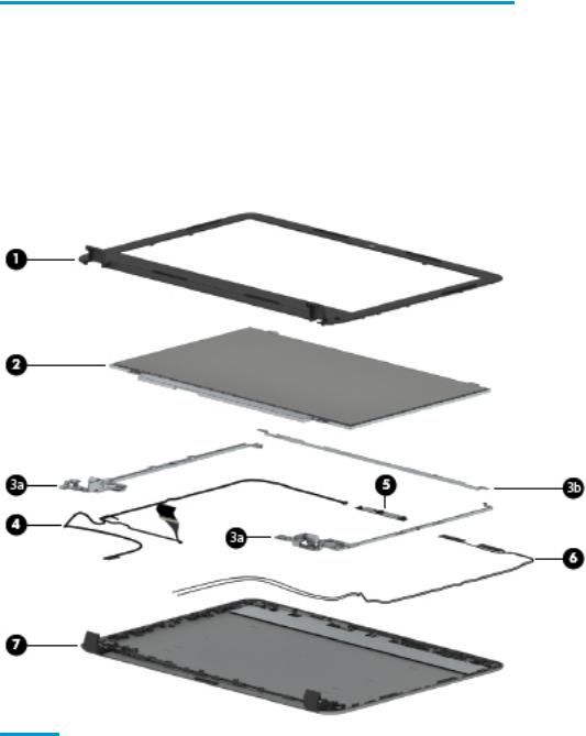
Display assembly subcomponents
Item |
Component |
Spare part number |
|
|
|
|
|
(1) |
Display bezel (includes insulator screws) |
858073-001 |
|
|
|
|
|
(2) |
Raw display panel (35.6-cm [14.0-in], HD, WLED, BrightView; includes insulator screws) |
|
|
|
|
|
|
|
For use in HP Notebook PC models: |
|
|
|
|
|
|
|
● |
FHD |
860573-001 |
|
|
|
|
|
● |
HD |
860574-001 |
|
|
|
|
|
For use in HP 245 G5 Notebook PC models: |
|
|
|
|
|
|
|
● |
HD |
864838-001 |
|
|
|
|
Display assembly subcomponents 19

Item |
Component |
Spare part number |
|
|
|
|
|
|
Hinges (left and right; includes insulator screws) |
|
|
|
|
|
|
(3a) |
Left and right hinges |
858076-001 |
|
|
|
|
|
(3b) |
Top hinge |
858702-001 |
|
|
|
|
|
(4) |
Display cable (includes display panel cable and webcam/microphone cable) |
|
|
|
|
|
|
|
For use with FHD displays (HP Notebook PC only) |
858074-001 |
|
|
|
|
|
|
For use with HD displays |
858075-001 |
|
|
|
|
|
(5) |
Webcam/microphone module (includes insulator screws) |
|
|
|
|
|
|
|
VGA |
|
860575-001 |
|
|
|
|
|
HD |
|
860576-001 |
|
|
|
|
(6) |
Antenna |
|
|
|
|
|
|
|
Single antenna |
813485-001 |
|
|
|
|
|
|
Dual antennas |
859127-001 |
|
|
|
|
|
(7) |
Display enclosure (includes insulator screws): |
|
|
|
|
|
|
|
For use in HP Notebook PC models: |
|
|
|
|
|
|
|
● |
Black models |
858065-001 |
|
|
|
|
|
● |
Red models |
858068-001 |
|
|
|
|
|
● |
White silver models |
858067-001 |
|
|
|
|
|
● |
Turbo silver models |
858066-001 |
|
|
|
|
|
● |
Blue models |
858070-001 |
|
|
|
|
|
For use in HP 245 G5 Notebook PC models |
860456-001 |
|
|
|
|
|
Mass storage devices
Component |
Spare part number |
|
|
eMMC drive, includes eMMC board, bracket, cable, foam, and screws |
|
|
|
64 GB |
903803-001 |
|
|
32 GB |
861964-001 |
|
|
Hard drive, SATA; does not include bracket or cable): |
|
|
|
1-TB, 5400-rpm, 2.5-in |
778192-005 |
|
|
500-GB, 5400-rpm, 7-mm |
778186-005 |
|
|
500-GB, 5400-rpm, hybrid 8 GB SSD, 7-mm |
732000-005 |
|
|
Hard drive bracket |
859126-001 |
|
|
Hard drive connector |
815139-001 |
|
|
20 Chapter 3 Illustrated parts catalog

4Removal and replacement procedures preliminary requirements
Tools required
You will need the following tools to complete the removal and replacement procedures:
●Flat-bladed screwdriver
●Magnetic screwdriver
●Phillips P0 and P1 screwdrivers
Service considerations
The following sections include some of the considerations that you must keep in mind during disassembly and assembly procedures.
 NOTE: As you remove each subassembly from the computer, place the subassembly (and all accompanying screws) away from the work area to prevent damage.
Plastic parts
 CAUTION: Using excessive force during disassembly and reassembly can damage plastic parts. Use care when handling the plastic parts. Apply pressure only at the points designated in the
maintenance instructions.
Cables and connectors
 CAUTION: When servicing the computer, be sure that cables are placed in their proper locations during the reassembly process. Improper cable placement can damage the computer.
Cables must be handled with extreme care to avoid damage. Apply only the tension required to unseat or seat the cables during removal and insertion. Handle cables by the connector whenever possible. In all cases, avoid bending, twisting, or tearing cables. Be sure that cables are routed in such a way that they cannot be caught or snagged by parts being removed or replaced. Handle flex cables with extreme care; these cables tear easily.
Tools required 21

Drive handling
 CAUTION: Drives are fragile components that must be handled with care. To prevent damage to the computer, damage to a drive, or loss of information, observe these precautions:
Before removing or inserting a hard drive, shut down the computer. If you are unsure whether the computer is o or in Hibernation, turn the computer on, and then shut it down through the operating system.
Before handling a drive, be sure that you are discharged of static electricity. While handling a drive, avoid touching the connector.
Before removing a diskette drive or optical drive, be sure that a diskette or disc is not in the drive and be sure that the optical drive tray is closed.
Handle drives on surfaces covered with at least one inch of shock-proof foam. Avoid dropping drives from any height onto any surface.
After removing a hard drive, an optical drive, or a diskette drive, place it in a static-proof bag.
Avoid exposing an internal hard drive to products that have magnetic elds, such as monitors or speakers. Avoid exposing a drive to temperature extremes or liquids.
If a drive must be mailed, place the drive in a bubble pack mailer or other suitable form of protective packaging and label the package “FRAGILE.”
Grounding guidelines
Electrostatic discharge damage
Electronic components are sensitive to electrostatic discharge (ESD). Circuitry design and structure determine the degree of sensitivity. Networks built into many integrated circuits provide some protection, but in many cases, ESD contains enough power to alter device parameters or melt silicon junctions.
A discharge of static electricity from a nger or other conductor can destroy static-sensitive devices or microcircuitry. Even if the spark is neither felt nor heard, damage may have occurred.
An electronic device exposed to ESD may not be a ected at all and can work perfectly throughout a normal cycle. Or the device may function normally for a while, then degrade in the internal layers, reducing its life expectancy.
 CAUTION: To prevent damage to the computer when you are removing or installing internal components, observe these precautions:
Keep components in their electrostatic-safe containers until you are ready to install them.
Before touching an electronic component, discharge static electricity by using the guidelines described in this section.
Avoid touching pins, leads, and circuitry. Handle electronic components as little as possible. If you remove a component, place it in an electrostatic-safe container.
The following table shows how humidity a ects the electrostatic voltage levels generated by di erent activities.
 CAUTION: A product can be degraded by as little as 700 V.
22 Chapter 4 Removal and replacement procedures preliminary requirements
Loading...