


HoshizakiHoshizaki America, Inc.
Stackable Square Cuber
Model
IM-500SAA
“A Superior Degree
of Reliability”
www.hoshizaki.com
SERVICE MANUAL
Number: M029-897
Issued: 2-8-2013
Revised: 5-19-2014

 WARNING
Only qualified service technicians should install and service the appliance. To obtain the name and phone number of your local Hoshizaki Certified Service Representative, visit www.hoshizaki.com. No service should be undertaken until the technician has thoroughly read this Service Manual. Failure to service and maintain the appliance in accordance with this manual will adversely affect safety, performance, component life, and warranty coverage and may result in costly water damage. Proper installation is the responsibility of the installer. Product failure or property damage due to improper installation is not covered under warranty.
Hoshizaki provides this manual primarily to assist qualified service technicians in the service of the appliance.
Should the reader have any questions or concerns which have not been satisfactorily addressed, please call, send an e-mail message, or write to the Hoshizaki Technical Support Department for assistance.
Phone: 1-800-233-1940; (770) 487-2331
Fax: 1-800-843-1056; (770) 487-3360
E-mail: techsupport@hoshizaki.com
HOSHIZAKI AMERICA, INC.
618 Highway 74 South
Peachtree City, GA 30269
Attn: Hoshizaki Technical Support Department
Web Site: www.hoshizaki.com
NOTE: To expedite assistance, all correspondence/communication MUST include the following information:
•Model Number
•Serial Number
•Complete and detailed explanation of the problem.
2
IMPORTANT |
|
This manual should be read carefully before the appliance is serviced. Read |
|
the warnings and guidelines contained in this manual carefully as they provide |
|
essential information for the continued safe use, service, and maintenance of the |
|
appliance. Retain this manual for any further reference that may be necessary. |
|
CONTENTS |
|
Important Safety Information ................................................................................................. |
4 |
I. Construction and Water/Refrigeration Circuit Diagram ....................................................... |
6 |
A. Construction.................................................................................................................. |
6 |
B. Water/Refrigeration Circuit Diagram.............................................................................. |
7 |
II. Sequence of Operation and Service Diagnosis................................................................. |
8 |
A. Sequence of Operation Flow Chart............................................................................... |
8 |
B. Sequence of Operation ................................................................................................. |
9 |
1. Startup Cycle............................................................................................................ |
9 |
2. Harvest Cycle .......................................................................................................... |
9 |
3. Freeze Cycle............................................................................................................ |
9 |
4. Shutdown............................................................................................................... |
10 |
C. Service Diagnosis Table............................................................................................... |
11 |
D. Bin Control Check and Cleaning ................................................................................. |
14 |
1. Bin Control Check .................................................................................................. |
14 |
2. Bin Control Cleaning.............................................................................................. |
15 |
E. Evaporator Thermistor Check...................................................................................... |
16 |
III. Controls and Adjustments............................................................................................... |
17 |
A. Control Switch ............................................................................................................. |
17 |
B. Control Board .............................................................................................................. |
17 |
1. Control Board Layout ............................................................................................. |
18 |
C. Control Buttons............................................................................................................ |
19 |
D. Control Board Settings ................................................................................................ |
20 |
E. Control Board Information Display .............................................................................. |
23 |
F. Control Board Model Code Setting .............................................................................. |
25 |
1. Control Board Replacement ................................................................................... |
25 |
2. Checking or Changing the Control Board Model Code.......................................... |
25 |
G. Error Codes ................................................................................................................ |
27 |
H. Quick Adjustments ...................................................................................................... |
28 |
1. Dimple Diameter .................................................................................................... |
28 |
2. Ice Clarity .............................................................................................................. |
29 |
IV. Refrigeration Circuit and Component Service Information.............................................. |
30 |
A. Refrigeration Circuit Service Information .................................................................... |
30 |
B. Component Service Information.................................................................................. |
32 |
V. Maintenance .................................................................................................................... |
34 |
VI. Preparing the Icemaker for Periods of Non-Use............................................................. |
35 |
VII. Disposal......................................................................................................................... |
36 |
VIII. Technical Information.................................................................................................... |
37 |
A. Specification Data ....................................................................................................... |
37 |
B. Performance Data ....................................................................................................... |
38 |
C. Wiring Diagram ........................................................................................................... |
39 |
3

Important Safety Information
Throughout this manual, notices appear to bring your attention to situations which could result in death, serious injury, damage to the appliance, or damage to property.
WARNING |
Indicates a hazardous situation which could result in death or |
|
serious injury. |
NOTICE |
Indicates a situation which could result in damage to the |
|
appliance or property. |
IMPORTANT |
Indicates important information about the use and care of the |
|
appliance. |
|
WARNING |
The appliance should be destined only to the use for which it has been expressly conceived. Any other use should be considered improper and therefore dangerous. The manufacturer cannot be held responsible for injury or damage resulting from improper, incorrect, and unreasonable use. Failure to service and maintain the appliance in accordance with this manual will adversely affect safety, performance, component life, and warranty coverage and may result in costly water damage.
To reduce the risk of death, electric shock, serious injury, or fire, follow basic precautions including the following:
•Only qualified service technicians should install and service this appliance.
•The appliance must be installed in accordance with applicable national, state, and local codes and regulations. Failure to meet these code requirements could result in death, electric shock, serious injury, fire, or damage to the appliance.
•Electrical connection must be hard-wired and must meet national, state, and local electrical code requirements. Failure to meet these code requirements could result in death, electric shock, serious injury, fire, or damage.
•The icemaker requires an independent power supply of proper capacity. See the nameplate for electrical specifications. Failure to use an independent power supply of proper capacity can result in a tripped breaker, blown fuse, damage to existing
wiring, or component failure. This could lead to heat generation or fire.
•THE ICEMAKER MUST BE GROUNDED. Failure to properly ground the icemaker could result in death or serious injury.
•To reduce the risk of electric shock, do not touch the control switch with damp hands.
•Move the control switch to the "OFF" position and turn off the power supply before servicing. Lockout/Tagout to prevent the power supply from being turned back on inadvertently.
•Do not make any alterations to the appliance. Alterations could result in electric shock, serious injury, fire, or damage.
4

 WARNING, continued
•The appliance is not intended for use by persons (including children) with reduced physical, sensory, or mental capabilities, or lack of experience and knowledge, unless they have been given supervision or instruction concerning use of the appliance by a person responsible for their safety.
•Children should be properly supervised around the appliance.
•Do not climb, stand, or hang on the appliance or allow children or animals to do so. Serious injury could occur or the appliance could be damaged.
•Do not use combustible spray or place volatile or flammable substances near the appliance. They might catch fire.
•Keep the area around the appliance clean. Dirt, dust, or insects in the appliance could cause harm to individuals or damage to the appliance.
NOTICE
•Follow the instructions in this manual carefully to reduce the risk of costly water damage.
•In areas where water damage is a concern, install in a contained area with a floor drain.
•Install the appliance in a location that stays above freezing. Normal operating ambient temperature must be within 45°F to 100°F (7°C to 38°C).
•Do not leave the appliance on during extended periods of non-use, extended absences, or in sub-freezing temperatures. To properly prepare the appliance for these occasions, follow the instructions in "VI. Preparing the Icemaker for Periods of Non-Use."
•Do not place objects on top of the appliance.
•The dispenser unit/ice storage bin is for ice use only. Do not store anything else in the dispenser unit/ice storage bin.
5

I. Construction and Water/Refrigeration Circuit Diagram
A.Construction
1.Air-Cooled Model (SAA)
Evaporator
Water Plate
Inlet Water Valve |
Thermostatic Expansion Valve |
Hot Gas Valve
High-Pressure
Switch
Condenser
Pump Motor
Actuator Motor
Fan Motor
Drain Pan |
|
Control Board Thermistor |
Drier |
|
|
Control Box |
Compressor |
|
Evaporator Thermistor |
|
Fuse Holder |
|
Control |
Water Tank |
Switch |
|
Bin Control
Model Shown: IM-500SAA
6
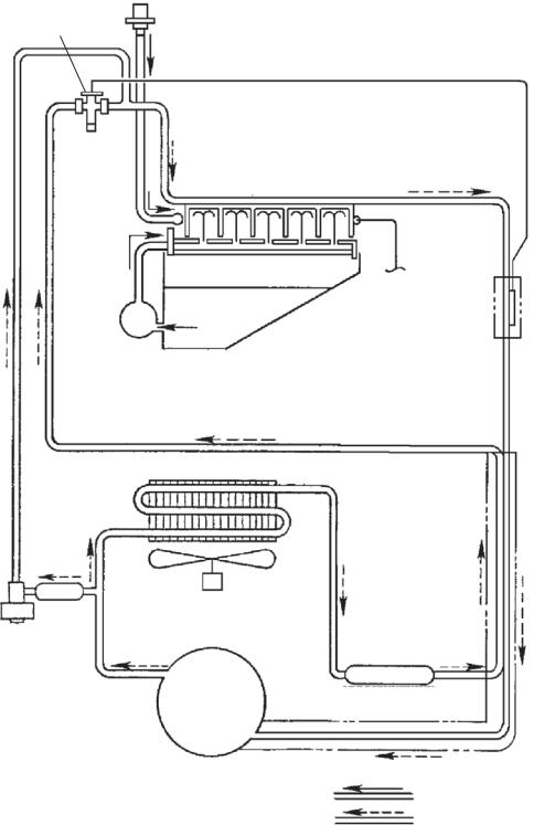
B.Water/Refrigeration Circuit Diagram
1.Air-Cooled Model (SAA)
Inlet
Water
Valve
Thermostatic Expansion Valve
Evaporator
Evaporator Thermistor
Water |
Water Tank |
|
|
Pump |
|
Condenser
Heat Exchanger
Hot Gas
Fan Motor
Valve Strainer
Compressor
Drier
Water Circuit
Refrigerant Circuit
7

II. Sequence of Operation and Service Diagnosis
A. Sequence of Operation Flow Chart
"IM" Control Board
Cycle |
|
1. 30-Sec. |
2. Harvest Cycle |
3. Freeze Cycle |
|
||||
Steps |
|
Startup |
• HGV: If CBT≤81°F (27°C) (CB Setting |
• Max. freeze time: 45 min. (CB Setting 6) |
|
|
Cycle |
74), HGV repeatedly energizes 40 sec./ |
|
|
|
|
de-energizes 40 sec. |
|
•FM: If CBT≥118°F (48°C) (CB Setting 34), FM operates continuously in harvest cycle
|
|
|
|
|
• Max. harvest time: 30 min. |
|
|
|
|
ET≤-1.3°F (-18.5°C) |
||||||||||
|
|
|
|
WV Delay |
ET≥41°F (5°C) |
PM Delay |
(CB Setting 2) |
|||||||||||||
|
|
|
|
|
|
|
|
|
|
|||||||||||
|
|
|
|
|
|
|
|
(CB Setting 1) |
|
|
|
|
|
|
|
Time varies based on |
|
|||
|
|
|
|
*1 |
|
|
*4 |
|
|
|
||||||||||
Startup |
|
|
|
|
|
|
|
|
|
|
|
|
|
control board calculation |
||||||
|
|
|
|
|
|
|
|
|
|
|
|
|
|
|
|
|
||||
|
|
|
|
|
|
|
|
|
|
|
|
|
|
|
|
|
|
|
|
|
|
|
|
|
|
|
|
|
Water Tank Closed |
|
|
|
|
|
|
|
|
|
|
||
|
|
|
|
|
|
|
|
|
|
|
|
|
|
|
|
|
|
|
|
|
HGV energized |
|
WV energized *2 (Actuator Motor PS) |
|
PM energized |
If CBT>81°F (27°C) (CB |
|||||||||||||||
|
|
|
|
|
HGV continues |
Comp continues |
Comp continues |
Setting 74) and CBT≤111°F |
||||||||||||
|
|
|
|
|
AMD energized |
AMU energized |
FM continues |
|
(44°C) (CB Setting 70), HGV |
|||||||||||
|
|
|
|
|
Comp energized |
FM energized |
WV energized *4+*5 |
energizes 5 sec./de-energizes |
||||||||||||
|
|
|
|
|
|
|
|
|
WV energized *3 |
|
|
|
|
|
25 sec./energizes 5 sec. (CB |
|||||
|
|
|
|
|
|
|
|
|
HGV de-energized |
|
|
|
|
|
Setting 71, 72) |
|||||
Shutdown and Restart Sequence Flow Chart
Shutdown |
|
|
1. Bin Full |
|
2. Icemaker Off |
|
3. Ice Level Lowered |
|||
|
|
|
||||||||
and Restart |
|
|
|
|
|
|
|
|||
BC Operation |
|
|
|
|
|
|
|
|
|
|
|
|
|
BC open 10 sec. or more |
All components |
BC closed 80 sec. or more |
|||||
|
|
|
|
|||||||
|
|
|
|
(BC actuator paddle |
de-energized. |
(BC actuator paddle |
||||
|
|
|
|
engaged). Shutdown |
|
|
disengaged). |
|||
|
|
|
|
occurs at end of harvest |
|
|
|
|
|
|
|
|
|
|
cycle. |
|
|
|
|
|
|
Icemaker restarts at
1. 30-Sec. Startup Cycle.
|
|
|
Initial Harvest and |
Initial Harvest and Initial Freeze after |
|
|
|||
|
CB |
|
Initial Freeze after |
|
Normal Harvest and Freeze |
||||
Note |
Setting |
|
Power On |
|
Bin Control Initiated Restart |
|
|
||
|
|
|
All WT |
|
WT>48°F (9°C) |
WT≤48°F (9°C) |
WT>48°F (9°C) |
WT≤48°F (9°C) |
|
*1 |
NA |
|
20 sec. |
|
0 sec. |
0 sec. |
20 sec. |
20 sec. |
|
*2 |
10, 11 |
|
95 sec. |
|
10 sec. (CB Setting NA) |
95 sec. |
30 sec. |
95 sec. |
|
*3 |
NA |
|
10 sec. |
|
0 sec. |
10 sec. |
0 sec. |
10 sec. |
|
PD*4 |
12 |
|
30 sec. × 2 |
|
30 sec. × 2 |
30 sec. × 2 |
30 sec. |
30 sec. |
|
PD*5 |
15 |
|
22 sec. × 2 |
|
22 sec. × 2 |
22 sec. × 2 |
22 sec. |
22 sec. |
|
FD*4 |
12 |
|
60 sec. |
|
60 sec. |
60 sec. |
60 sec. |
60 sec. |
|
FD*5 |
15 |
|
44 sec. |
|
44 sec. |
44 sec. |
44 sec. |
44 sec. |
|
|
|
|
|
|
|
|
|
|
|
Legend: |
|
FM–fan motor |
|
|
|
|
|||
AMD–actuator motor down |
|
|
|
|
|||||
AMU–actuator motor up |
HGV–hot gas valve |
|
|
|
|
||||
BC–bin control |
|
PD–partial drain (CB Setting 14) |
|
|
|
||||
CBT–control board thermistor |
PM–pump motor |
|
|
|
|
||||
Comp–compressor |
PS–position sensor |
|
|
|
|
||||
ET–evaporator thermistor |
WT–water temperature |
|
|
|
|
||||
FD–full drain (CB Setting 14) |
WV–inlet water valve |
|
|
|
|
||||
|
|
|
|
|
|
|
|
|
|
8
B. Sequence of Operation
1. Startup Cycle
When power supply is turned on, "on" appears on CB display and HGV energizes. 30 sec. later, harvest cycle starts.
•If the "RESET" button is pressed during 30-sec. startup cycle time, startup cycle ends immediately and harvest cycle starts.
2.Harvest Cycle
HGV continues. Comp and AMD energize. WV energizes as listed in table below.
|
CB |
Initial Harvest |
Initial Harvest after Bin Control |
Normal Harvest |
|||
Note |
after Power On |
Initiated Restart |
|||||
Setting |
|
|
|||||
|
All WT |
WT>48°F (9°C) |
WT≤48°F (9°C) |
WT>48°F (9°C) |
WT≤48°F (9°C) |
||
|
|
||||||
WV Delay |
NA |
20 sec. |
0 sec. |
0 sec. |
20 sec. |
20 sec. |
|
WV Time after |
10, 11 |
95 sec. |
10 sec. |
95 sec. |
30 sec. |
95 sec. |
|
WV Delay |
|
|
(CB Setting NA) |
|
|
|
|
WV Time |
NA |
10 sec. |
0 sec. |
10 sec. |
0 sec. |
10 sec. |
|
when |
|
|
|
|
|
|
|
ET≥41°F |
|
|
|
|
|
|
|
(5°C) |
|
|
|
|
|
|
|
(CB Setting 1) |
|
|
|
|
|
|
|
Note: ET temperature is recorded 30 seconds after PM energizes in the preceding freeze cycle. Water temperature correction value (CB Setting 13) is added to ET temperature and this is used as WT value.
If CBT≤81°F (27°C) (CB Setting 74) at beginning of harvest cycle, HGV repeatedly energizes 40 sec./de-energizes 40 sec. If CBT≥118°F (48°C) (CB Setting 34) at beginning of harvest cycle, FM operates continuously in harvest cycle.
When ET reaches harvest cycle termination temperature (CB Setting 1) of 41°F (5°C) , HGV de-energizes, FM and AMU energize. Comp continues. WV energizes as listed in table above. Harvest cycle is complete when actuator motor PS indicates water tank is fully closed.
3. Freeze Cycle
Comp and FM continue. WV energizes for total time of WV Time 1 and WV Time 2 listed in table below. PM energizes after PM delay listed in table below.
|
CB |
Initial Freeze |
Initial Freeze after Bin Control |
Normal Freeze |
|
Note |
after Power On |
Initiated Restart |
|||
Setting |
|
||||
|
All WT |
All WT |
All WT |
||
|
|
||||
PD |
12 |
30 sec. × 2 |
30 sec. × 2 |
30 sec. |
|
WV Time 1 |
|
|
|
|
|
and PM Delay |
|
|
|
|
|
PD |
15 |
22 sec. × 2 |
22 sec. × 2 |
22 sec. |
|
WV Time 2 |
|
|
|
|
|
FD |
12 |
60 sec. |
60 sec. |
60 sec. |
|
WV Time 1 |
|
|
|
|
|
and PM Delay |
|
|
|
|
|
FD |
15 |
44 sec. |
44 sec. |
44 sec. |
|
WV Time 2 |
|
|
|
|
9
ET temperature is recorded 30 seconds after PM energizes. Water temperature correction value (CB Setting 13) is added to ET temperature and this is used as WT value in following harvest cycle.
If CBT>81°F (27°C) (CB Setting 74) and CBT≤111°F (44°C) (CB Setting 70), when ET≤-1.3°F (-18.5°C) (CB Setting 2), HGV energizes 5 sec., de-energizes 25 sec., energizes 5 sec. (CB Settings 71 and 72) to reduce bonding of the water tank to the evaporator.
CB monitors time after ET temperature≤32°F (0°C). CB terminates freeze cycle when the
following equation is satisfied:
temp. (absolute value) × time (min.) = (absolute value of CB Setting 2) × (CB Setting 3)
Using default settings, freeze cycle is terminated when: temp. (absolute value) × time (min.) = 185
This formula helps maintain consistent dimple size regardless of differences in seasonal ambient and water temperatures.
4. Shutdown
When BC is engaged (open) for more than 10 seconds, the icemaker shuts down after harvest cycle.
When BC is disengaged (closed) for more than 80 seconds, icemaker restarts at startup cycle.
If BC is engaged (open) while the water tank is opening after the power supply is turned on (or after the "RESET" button is pressed), shutdown does not start: Shutdown occurs 10 seconds after actuator motor's internal position sensor indicates water tank is fully open.
Legend: AMD–actuator motor down; AMU–actuator motor up; BC–bin control; CB–control board; CBT–control board thermistor; Comp–compressor; ET–evaporator thermistor; FD–full drain (CB Setting 14); FM–fan motor; HGV–hot gas valve; PM–pump motor; PD–partial drain (CB Setting 14); PS–position sensor; WT–water temperature; WV–inlet water valve
10
C. Service Diagnosis Table
First see "III.G. Error Codes." If there are no recorded errors, refer to the table below.
No Ice Production - Possible Cause
1. Power Supply |
a) Off, blown fuse, or tripped breaker. |
||
|
|
|
|
|
|
b) Not within specifications. |
|
2. Fuse (Control Box) |
a) Blown. |
||
|
|
|
|
3. Control Switch |
a) In "OFF" or "WASH" position. |
||
|
|
|
|
|
|
b) Bad contacts. |
|
|
|
|
|
4. High-Pressure Switch |
a) Dirty condenser or air filter. |
||
|
|
|
|
|
|
b) Fan motor not operating. |
|
|
|
|
|
|
|
c) Refrigerant overcharged. |
|
|
|
|
|
|
|
d) Bad contacts. |
|
|
|
|
|
|
|
e) Refrigerant lines or components restricted. |
|
|
|
|
|
5. Control Transformer |
a) Coil winding open or shorted. |
||
(115VAC/10.5VAC) |
|
||
|
|
|
|
6. Control Board |
a) Error. See "III.G. Error Codes." |
||
|
|
|
|
|
|
b) Defective. |
|
7. Bin Control |
a) Tripped with bin filled with ice. |
||
See "II.D. Bin Control Check and |
|
||
b) Actuator does not move freely. |
|||
Cleaning" |
|
||
c) Defective. |
|||
|
|
||
|
|
|
|
8. Water Supply |
a) Water supply off or improper water pressure. |
||
|
|
|
|
|
|
b) External water filters restricted. |
|
|
|
|
|
9. Inlet Water Valve |
a) Screen or orifice restricted. |
||
|
|
|
|
|
|
b) Coil winding open. |
|
10. Compressor |
a) Compressor relay/magnetic contactor contacts bad or coil winding |
||
|
|
open. |
|
|
|
b) Start capacitor or run capacitor defective (single phase). |
|
|
|
|
|
|
|
c) Internal protector open. |
|
|
|
|
|
|
|
d) Start relay contacts bad or coil winding open (single phase). |
|
|
|
|
|
|
|
e) Defective. |
|
|
|
|
|
11. Hot Gas Valve |
a) Defective. |
||
|
|
|
|
12. Evaporator (Cube Control) |
a) Loose, disconnected, or defective. |
||
Thermistor |
|
||
See "II.E. Evaporator Thermistor |
|
||
Check" |
|
||
|
|
|
|
13. Pump Motor |
a) Mechanical seal worn out. |
||
|
|
|
|
|
|
b) Defective. |
|
|
|
|
|
|
|
c) Defective capacitor. |
|
14. Thermostatic Expansion Valve |
a) Bulb loose. |
||
|
|
|
|
|
|
b) Defective. |
|
|
|
|
|
15. Fan Motor |
a) Defective. |
||
|
|
b) Defective capacitor. |
|
|
|
|
|
16. Water System |
a) Water leaks. |
||
|
|
|
|
11

Low Ice Production - Possible Cause
|
Long Harvest Cycle |
1. Evaporator |
a) Scaled up. |
2. Refrigerant Charge |
a) Low. |
|
|
3. Control Board |
a) Thermistor connection loose (K3). |
|
|
|
b) Defective. |
4. Evaporator (Cube Control) |
a) Loose, disconnected, or defective. |
Thermistor |
|
See "II.E. Evaporator Thermistor |
|
Check" |
|
|
|
5. Hot Gas Valve |
a) Erratic or closed. |
6. Compressor |
a) Inefficient or off. |
|
|
7. Thermostatic Expansion Valve |
a) Defective. |
|
|
|
Long Freeze Cycle |
1. Evaporator |
a) Scaled up, dirty. |
|
|
2. Hot Gas Valve |
a) Defective. |
|
|
3. Condenser |
a) Restricted. |
4. Control Board |
a) Defective. |
|
|
5. Refrigerant Charge |
a) Low. |
|
|
6. Thermostatic Expansion Valve |
a) Bulb loose. |
|
b) Defective. |
|
|
7. Compressor |
a) Inefficient or off. |
|
|
|
|
Slab Does Not Break Into Separate Cubes - Possible Cause |
|
1. Spring |
a) Over-extended. |
|
|
2. Water Plate |
a) Obstacle caught between evaporator and water plate. |
|
|
Cubes Drop Separately - Possible Cause |
|
|
|
1. Refrigerant Charge |
a) Low - Long harvest cycle. |
|
|
2. Cam Arm |
a) Worn out. |
|
|
|
|
Imperfect Ice Production - Possible Cause |
|
|
|
1. Water Supply |
a) Improper water pressure. |
|
b) External water filters restricted. |
|
|
|
c) Water leaks from water tank or water plate due to broken tank or |
|
plate or icemaker out of level. |
|
|
2. Inlet Water Valve |
a) Water leaks from valve body or water supply pipe joint. |
|
|
3. Water Plate |
a) Spray holes restricted. |
|
|
4. Pump Motor |
a) Defective. |
|
|
|
|
Large-Hole Cubes - Possible Cause (Also see III.H.1. Dimple Diameter") |
|
|
|
1. Refrigerant Charge |
a) Low. |
|
|
2. Condenser |
a) Dirty condenser or air filter. |
|
|
3. Fan Motor |
a) Defective. |
|
|
12
 Loading...