


Reliability is a beautiful thingTM
MODULAR CRESCENT CUBER
KM-500MAH
KM-500MWH
KM-500MRH
SERVICE MANUAL
|
NUMBER: |
73104 |
|
™ |
ISSUED: |
NOV. 7, |
2002 |
|
REVISED: |
DEC. 16, |
2003 |
IMPORTANT
Only qualified service technicians should attempt to service or maintain this icemaker. No service or maintenance should be undertaken until the technician has thoroughly read this Service Manual.
HOSHIZAKI provides this manual primarily to assist qualified service technicians in the service and maintenance of the icemaker.
Should the reader have any questions or concerns which have not been satisfactorily addressed, please call or write to the HOSHIZAKI Technical Support Department for assistance.
HOSHIZAKI AMERICA, INC.
618 Highway 74 South
Peachtree City, GA 30269
Attn: HOSHIZAKI Technical Support Department
Phone: 1-800-233-1940 Technical Service
|
(770) 487-2331 |
Fax: |
(770) 487-3360 |
NOTE: To expedite assistance, all correspondence/communication MUST include the following information:
•Model Number
•Serial Number
•Complete and detailed explanation of the problem
2
•Please review this manual. It should be read carefully before the icemaker is serviced or maintenance operations performed. Only qualified service technicians should service and maintain the icemaker. This manual should be made available to the technician prior to service or maintenance.
CONTENTS |
|
|
PAGE |
I.SPECIFICATIONS ...................................................................................................... |
5 |
1. KM-500MAH (Air-cooled) ..................................................................................... |
5 |
2a. KM-500MWH (Water-cooled) Serial #L00001D - M20960C .............................. |
6 |
2b. KM-500MWH Serial #M30961D ........................................................................ |
7 |
3. KM-500MRH (Remote air-cooled) ........................................................................ |
8 |
4. CONDENSER UNIT, URC-6F .............................................................................. |
9 |
II.GENERALINFORMATION ...................................................................................... |
11 |
1. CONSTRUCTION............................................................................................... |
11 |
[a] KM-500MAH (Air-cooled) ............................................................................. |
11 |
[b] KM-500MWH (Water-cooled) ....................................................................... |
12 |
[c] KM-500MRH (Remote air-cooled) ................................................................ |
13 |
2. CONTROLLER BOARD ..................................................................................... |
14 |
[a] SOLID-STATE CONTROL ........................................................................... |
14 |
[b] CONTROLLER BOARD ............................................................................... |
14 |
[c] SEQUENCE ................................................................................................ |
18 |
[d] CONTROLS AND ADJUSTMENTS ............................................................. |
20 |
[e] CHECKING CONTROLLER BOARD ........................................................... |
24 |
3. MECHANICAL BIN CONTROL........................................................................... |
26 |
[a] PROXIMITYSWITCH ................................................................................... |
26 |
[b] EXPLANATION OF OPERATION................................................................ |
26 |
[c] TROUBLESHOOTING ................................................................................. |
27 |
III. TECHNICALINFORMATION .................................................................................. |
28 |
1. WATER CIRCUIT AND REFRIGERANT CIRCUIT .............................................. |
28 |
[a] KM-500MAH ................................................................................................ |
28 |
[b] KM-500MWH ............................................................................................... |
29 |
[c] KM-500MRH ................................................................................................ |
30 |
2. WIRING DIAGRAMS .......................................................................................... |
31 |
[a] KM-500MAH and KM-500MWH ................................................................... |
31 |
[b] KM-500MRH ................................................................................................ |
33 |
3. TIMING CHART .................................................................................................. |
35 |
4. PERFORMANCE DATA .................................................................................... |
37 |
[a] KM-500MAH ................................................................................................ |
37 |
[b] KM-500MWHSerial #L00001D - M20960C .................................................. |
38 |
[c] KM-500MWH Serial #M30961D .................................................................. |
39 |
[d] KM-500MRH ................................................................................................ |
40 |
3
IV. SERVICE DIAGNOSIS........................................................................................... |
41 |
|
1. NO ICE PRODUCTION......................................................................................... |
41 |
|
2. |
EVAPORATOR IS FROZEN UP .......................................................................... |
42 |
3. LOW ICE PRODUCTION ...................................................................................... |
42 |
|
4. |
ABNORMAL ICE .................................................................................................. |
45 |
5. |
OTHERS .............................................................................................................. |
45 |
V. REMOVAL AND REPLACEMENT OF COMPONENTS ............................................ |
46 |
|
1. |
SERVICE FOR REFRIGERANT LINES .............................................................. |
46 |
|
[a] REFRIGERANT RECOVERY ........................................................................ |
46 |
|
[b] EVACUATION AND RECHARGE .................................................................. |
46 |
2. |
BRAZING ............................................................................................................. |
47 |
3. REMOVAL AND REPLACEMENT OF COMPRESSOR ....................................... |
48 |
|
4. |
REMOVAL AND REPLACEMENT OF DRIER ..................................................... |
50 |
5. |
REMOVAL AND REPLACEMENT OF EXPANSION VALVE ............................... |
50 |
6. |
REMOVAL AND REPLACEMENT OF HOT GAS VALVE AND ............................... |
|
|
LINE VALVE ........................................................................................................ |
51 |
7. REMOVAL AND REPLACEMENT OF EVAPORATOR ........................................ |
52 |
|
8. |
REMOVAL AND REPLACEMENT OF WATER-REGULATING VALVE .................. |
|
|
- WATER COOLED MODEL ONLY ..................................................................... |
54 |
9. |
ADJUSTMENT OF WATER-REGULATING VALVE ................................................ |
|
|
- WATER COOLED MODEL ONLY ..................................................................... |
55 |
10. REMOVAL AND REPLACEMENT OF CONDENSING PRESSURE ........................ |
|
|
|
REGULATOR (C.P.R.) - REMOTE AIR-COOLED MODEL ONLY ....................... |
56 |
11. REMOVAL AND REPLACEMENT OF THERMISTOR .......................................... |
57 |
|
12. REMOVAL AND REPLACEMENT OF FAN MOTOR ............................................ |
58 |
|
13. REMOVAL AND REPLACEMENT OF WATER VALVE........................................ |
59 |
|
14. REMOVAL AND REPLACEMENT OF PUMP MOTOR ......................................... |
59 |
|
15. REMOVAL AND REPLACEMENT OF SPRAY TUBES ........................................ |
60 |
|
VI. CLEANING AND MAINTENANCE INSTRUCTIONS ............................................... |
61 |
|
1. |
PREPARING THE ICEMAKER FOR LONG STORAGE ...................................... |
61 |
2. |
CLEANING AND SANITIZING PROCEDURES ................................................... |
63 |
|
[a] CLEANING PROCEDURE ............................................................................. |
64 |
|
[b] SANITIZING PROCEDURE ........................................................................... |
66 |
3. MAINTENANCE.................................................................................................... |
67 |
|
4
I. SPECIFICATIONS
1. KM-500MAH
AC SUPPLY VOLTAGE |
115/60/1 |
|
|
|
|
|
|
AMPERAGE |
13 A ( 5 Min. Freeze AT 104°F / WT 80°F) |
|
|||||
MINIMUM CIRCUIT AMPACITY |
20 A |
|
|
|
|
|
|
MAXIMUM FUSE SIZE |
20 A |
|
|
|
|
|
|
APPROXIMATE ICE PRODUCTION |
Ambient |
|
WATER TEMP. (°F) |
||||
PER 24 HR. |
Temp.(°F) |
50 |
|
70 |
|
90 |
|
lbs./day ( kg/day ) |
|
70 |
*499 (226) |
|
468 (212) |
|
428 (194) |
Reference without *marks |
|
80 |
475 (216) |
|
427 (194) |
|
389 (176) |
|
|
90 |
468 (212) |
|
*393 (178) |
|
353 (160) |
SHAPE OF ICE |
100 |
461 (209) |
|
384 (174) |
|
317 (144) |
|
Crescent Cube |
|
|
|
|
|
||
ICE PRODUCTION PER CYCLE |
9.5 lbs. ( 4.3 kg ) 480 pcs. |
|
|
|
|
||
APPROXIMATE STORAGE CAPACITY |
N/A |
|
|
|
|
|
|
ELECTRIC & WATER CONSUMPTION |
90/70°F |
|
|
70/50°F |
|
||
ELECTRIC W (kWH/100 lbs.) |
1212 (7.4) |
|
1164 (5.6) |
|
|
||
WATER gal./24HR (gal./100 lbs.) |
113 (28.8) |
|
250 (50.1) |
|
|
||
EXTERIOR DIMENSIONS (WxDxH) |
22" x 27-3/8" x 30-5/6" (560 x 695 x 770 mm) |
|
|||||
EXTERIOR FINISH |
Stainless Steel, Galvanized Steel (Rear) |
|
|||||
WEIGHT |
Net 151 lbs. ( 69 kg ), Shipping 175 lbs. (80 kg) |
||||||
CONNECTIONS - ELECTRIC |
Permanent - Connection |
|
|
|
|
||
- WATER SUPPLY |
Inlet |
1/2" FPT |
|
|
|
|
|
- DRAIN |
Outlet |
3/4" FPT |
|
|
|
|
|
|
|
3/8" OD Pipe |
|
|
|
|
|
CUBE CONTROL SYSTEM |
Float Switch |
|
|
|
|
|
|
HARVESTING CONTROL SYSTEM |
Hot Gas and Water, Thermistor and Timer |
|
|||||
ICE MAKING WATER CONTROL |
Timer Controlled. Overflow Pipe |
|
|||||
COOLING WATER CONTROL |
N/A |
|
|
|
|
|
|
BIN CONTROL SYSTEM |
Proximity Switch with Delay |
|
|
|
|
||
COMPRESSOR |
Hermetic, Model AKA9455ZXA |
|
|||||
CONDENSER |
Air-cooled, Fin and tube type |
|
|||||
EVAPORATOR |
Vertical type, |
Stainless Steel and Copper |
|
||||
REFRIGERANT CONTROL |
Thermostatic Expansion Valve |
|
|||||
REFRIGERANT CHARGE |
R-404A, |
1 lb. 10 oz. ( 735 g ) |
|
||||
DESIGN PRESSURE |
High 467 PSIG, Low 230 PSIG |
|
|||||
P.C. BOARD CIRCUIT PROTECTION |
High Voltage Cut-out ( Internal ) |
|
|||||
COMPRESSOR PROTECTION |
Auto-reset Overload Protector ( Internal ) |
|
|||||
REFRIGERANT CIRCUIT PROTECTION |
Auto-reset High Pressure Control Switch |
|
|||||
LOW WATER PROTECTION |
Float Switch |
|
|
|
|
|
|
ACCESSORIES -SUPPLIED |
N/A |
|
|
|
|
|
|
-REQUIRED |
Ice Storage Bin |
|
|
|
|
||
OPERATING CONDITIONS |
VOLTAGE RANGE |
|
|
|
104 - 127 V |
||
|
AMBIENT TEMP. |
|
|
|
45 -100° F |
||
|
WATER SUPPLY TEMP. |
|
|
|
45 - 90° F |
||
|
WATER SUPPLY PRESSURE |
10 - 113 PSIG |
|||||
Note: We reserve the right to make changes in specifications and design without prior notice.
5

2a. KM-500MWH |
Serial #L00001D - M20960C |
|
|
||||
|
|
|
|
|
|
|
|
AC SUPPLY VOLTAGE |
115/60/1 |
|
|
|
|
|
|
AMPERAGE |
10 A |
( 5 Min. Freeze AT 104°F / WT 80°F) |
|
|
|||
MINIMUM CIRCUIT AMPACITY |
20 A |
|
|
|
|
|
|
MAXIMUM FUSE SIZE |
20 A |
|
|
|
|
|
|
APPROXIMATE ICE PRODUCTION |
Ambient |
|
WATER TEMP. (°F) |
|
|||
PER 24 HR. |
Temp.(°F) |
50 |
|
70 |
|
90 |
|
lbs./day ( kg/day ) |
|
70 |
*463 (210) |
|
448 (203) |
|
423 (192) |
Reference without *marks |
|
80 |
451 (205) |
|
428 (194) |
|
401 (180) |
|
|
90 |
448 (203) |
|
*411 (186) |
|
385 (175) |
SHAPE OF ICE |
100 |
442 (200) |
|
405 (184) |
|
361 (164) |
|
Crescent Cube |
|
|
|
|
|
||
ICE PRODUCTION PER CYCLE |
9.5 lbs. ( 4.3 kg ) 480 pcs. |
|
|
|
|
||
APPROXIMATE STORAGE CAPACITY |
N/A |
|
|
|
|
|
|
ELECTRIC & WATER CONSUMPTION |
90/70°F |
|
|
70/50°F |
|
|
|
ELECTRIC W (kWH/100 lbs.) |
1130 (6.6) |
|
1100 (5.7) |
|
|
||
WATER gal./24HR (gal./100 lbs.) |
135 (32) |
|
245 (52.8) |
|
|
||
WATER COOLED CONDENSER |
723 (176) |
|
380 (82) |
|
|
||
gal./24HR (gal./100 lbs.) |
|
|
|
|
|
|
|
EXTERIOR DIMENSIONS (WxDxH) |
22" x 27-3/8" x 30-5/16" (560 x 695 x 770 mm) |
|
|||||
EXTERIOR FINISH |
Stainless Steel, Galvanized Steel (Rear) |
|
|
||||
WEIGHT |
Net 146 lbs. ( 66 kg ), Shipping 170 lbs. (77 kg.) |
|
|||||
CONNECTIONS - ELECTRIC |
Permanent - Connection |
|
|
|
|
||
- WATER SUPPLY |
Inlet |
1/2" FPT |
|
Condenser Inlet |
1/2" FPT |
||
- DRAIN |
Outlet |
3/4" FPT |
|
Condenser Outlet |
3/8" FPT |
||
|
3/8" OD Pipe |
|
|
|
|
|
|
CUBE CONTROL SYSTEM |
Float Switch |
|
|
|
|
|
|
HARVESTING CONTROL SYSTEM |
Hot Gas and Water, Thermistor and Timer |
|
|
||||
ICE MAKING WATER CONTROL |
Timer Controlled. Overflow Pipe |
|
|
||||
COOLING WATER CONTROL |
Pressure Regulator |
|
|
|
|
||
BIN CONTROL SYSTEM |
Proximity Switch with Delay |
|
|
|
|
||
COMPRESSOR |
Hermetic, Model AKA9455ZXA |
|
|
||||
CONDENSER |
Water-cooled, Tube in tube type |
|
|
||||
EVAPORATOR |
Vertical type, |
Stainless Steel and Copper |
|
|
|||
REFRIGERANT CONTROL |
Thermostatic Expansion Valve |
|
|
||||
REFRIGERANT CHARGE |
R-404A, |
13.2 oz. ( 375 g ) |
|
|
|||
DESIGN PRESSURE |
High 427 PSIG, Low 230 PSIG |
|
|
||||
P.C. BOARD CIRCUIT PROTECTION |
High Voltage Cut-out ( Internal ) |
|
|
||||
COMPRESSOR PROTECTION |
Auto-reset Overload Protector ( Internal ) |
|
|
||||
REFRIGERANT CIRCUIT PROTECTION |
Auto-reset High Pressure Control Switch |
|
|
||||
LOW WATER PROTECTION |
Float Switch |
|
|
|
|
|
|
ACCESSORIES -SUPPLIED |
N/A |
|
|
|
|
|
|
-REQUIRED |
Ice Storage Bin |
|
|
|
|
||
OPERATING CONDITIONS |
VOLTAGE RANGE |
|
|
|
104 - 127 V |
||
|
AMBIENT TEMP. |
|
|
|
45 -100° F |
||
|
WATER SUPPLY TEMP. |
|
|
|
45 - 90° F |
||
|
WATER SUPPLY PRESSURE |
10 - 113 PSIG |
|||||
Note: We reserve the right to make changes in specifications and design without prior notice.
6

2b. KM-500MWH |
Serial #M30961D - |
|
|
|
|
||
|
|
|
|
|
|
|
|
AC SUPPLY VOLTAGE |
115/60/1 |
|
|
|
|
|
|
AMPERAGE |
10 A |
( 5 Min. Freeze AT 104°F / WT 80°F) |
|
|
|||
MINIMUM CIRCUIT AMPACITY |
20 A |
|
|
|
|
|
|
MAXIMUM FUSE SIZE |
20 A |
|
|
|
|
|
|
APPROXIMATE ICE PRODUCTION |
Ambient |
|
WATER TEMP. (°F) |
||||
PER 24 HR. |
Temp.(°F) |
50 |
|
70 |
|
90 |
|
lbs./day ( kg/day ) |
|
70 |
*480 (218) |
|
471 (213) |
|
439 (199) |
Reference without *marks |
|
80 |
473 (214) |
|
458 (208) |
|
417 (189) |
|
|
90 |
471 (213) |
|
*448 (203) |
|
410 (186) |
SHAPE OF ICE |
100 |
458 (208) |
|
439 (199) |
|
375 (170) |
|
Crescent Cube |
|
|
|
|
|
||
ICE PRODUCTION PER CYCLE |
9.5 lbs. (4.3 kg) 480 pcs. |
|
|
|
|
||
APPROXIMATE STORAGE CAPACITY |
N/A |
|
|
|
|
|
|
ELECTRIC & WATER CONSUMPTION |
90/70°F |
|
|
70/50°F |
|
|
|
ELECTRIC W (kWH/100 lbs.) |
1157 (6.2) |
|
1140 (5.7) |
|
|
||
WATER gal./24HR (gal./100 lbs.) |
133 (29.7) |
|
268 (55.8) |
|
|
||
WATER COOLED CONDENSER |
699 (156) |
|
394 (82) |
|
|
||
gal./24HR (gal./100 lbs.) |
|
|
|
|
|
|
|
EXTERIOR DIMENSIONS (WxDxH) |
22" x 27-3/8" x 30-5/16" (560 x 695 x 770 mm) |
|
|||||
EXTERIOR FINISH |
Stainless Steel, Galvanized Steel (Rear) |
|
|
||||
WEIGHT |
Net 146 lbs. ( 66 kg ), Shipping 170 lbs. ( 77 kg ) |
|
|||||
CONNECTIONS - ELECTRIC |
Permanent - Connection |
|
|
|
|
||
- WATER SUPPLY |
Inlet |
1/2" FPT |
|
Condenser Inlet |
1/2" FPT |
||
- DRAIN |
Outlet |
3/4" FPT |
|
Condenser Outlet |
3/8" FPT |
||
|
3/8" OD Pipe |
|
|
|
|
|
|
CUBE CONTROL SYSTEM |
Float Switch |
|
|
|
|
|
|
HARVESTING CONTROL SYSTEM |
Hot Gas and Water, Thermistor and Timer |
|
|
||||
ICE MAKING WATER CONTROL |
Timer Controlled. Overflow Pipe |
|
|
||||
COOLING WATER CONTROL |
Pressure Regulator |
|
|
|
|
||
BIN CONTROL SYSTEM |
Proximity Switch with Delay |
|
|
|
|
||
COMPRESSOR |
Hermetic, Model AKA9455ZXA |
|
|
||||
CONDENSER |
Water-cooled, Tube in tube type |
|
|
||||
EVAPORATOR |
Vertical type, |
Stainless Steel and Copper |
|
|
|||
REFRIGERANT CONTROL |
Thermostatic Expansion Valve |
|
|
||||
REFRIGERANT CHARGE |
R-404A, |
15 oz. ( 425 g ) |
|
|
|||
DESIGN PRESSURE |
High 427 PSIG, Low 206 PSIG |
|
|
||||
P.C. BOARD CIRCUIT PROTECTION |
High Voltage Cut-out ( Internal ) |
|
|
||||
COMPRESSOR PROTECTION |
Auto-reset Overload Protector ( Internal ) |
|
|
||||
REFRIGERANT CIRCUIT PROTECTION |
Auto-reset High Pressure Control Switch |
|
|
||||
LOW WATER PROTECTION |
Float Switch |
|
|
|
|
|
|
ACCESSORIES -SUPPLIED |
N/A |
|
|
|
|
|
|
-REQUIRED |
Ice Storage Bin |
|
|
|
|
||
OPERATING CONDITIONS |
VOLTAGE RANGE |
|
|
|
104 - 127 V |
||
|
AMBIENT TEMP. |
|
|
|
45 -100° F |
||
|
WATER SUPPLY TEMP. |
|
|
|
45 - 90° F |
||
|
WATER SUPPLY PRESSURE |
10 - 113 PSIG |
|||||
7
3. KM-500MRH
AC SUPPLY VOLTAGE |
115/60/1 |
|
|
|
|
|
AMPERAGE |
15 A ( 5 Min. Freeze AT 104°F / WT 80°F) |
|
||||
MINIMUM CIRCUIT AMPACITY |
20 A |
|
|
|
|
|
MAXIMUM FUSE SIZE |
20 A |
|
|
|
|
|
APPROXIMATE ICE PRODUCTION |
Ambient |
|
WATER TEMP. (°F) |
|||
PER 24 HR. |
Temp.(°F) |
50 |
|
70 |
90 |
|
lbs./day ( kg/day ) |
70 |
*517 235) |
|
493 (224) |
449 (204) |
|
Reference without *marks |
80 |
499(226) |
|
462 (210) |
411 (187) |
|
|
90 |
493 (224) |
|
*436 (198) |
387 (176) |
|
SHAPE OF ICE |
100 |
480 (218) |
|
425 (193) |
342 (155) |
|
Crescent Cube |
480 |
|
|
|
||
ICE PRODUCTION PER CYCLE |
9.5 lbs. |
(4.3 kg ) 480 pcs. |
|
|
|
|
APPROXIMATE STORAGE CAPACITY |
N/A |
|
|
|
|
|
ELECTRIC & WATER CONSUMPTION |
90/70°F |
|
|
|
70/50°F |
|
ELECTRIC W (kWH/100 lbs.) |
1272 (7.0) |
|
1206 (5.6) |
|
||
WATER gal./24HR (gal./100 lbs.) |
137 (31.3) |
|
233 (45.1) |
|
||
EXTERIOR DIMENSIONS (WxDxH) |
22" x 27-3/8" x 30-5/16" (560 x 695 x 770 mm) |
|||||
EXTERIOR FINISH |
Stainless Steel, Galvanized Steel (Rear) |
|
||||
WEIGHT |
Net 151 lbs. ( 69 kg ), Shipping 175 lbs. ( 80 kg ) |
|||||
CONNECTIONS - ELECTRIC |
Permanent - Connection |
|
|
|
||
- WATER SUPPLY |
Inlet |
1/2" FPT |
|
|
|
|
- DRAIN |
Outlet |
3/4" FPT |
|
|
|
|
|
|
3/8" OD Pipe |
|
|
|
|
CUBE CONTROL SYSTEM |
Float Switch |
|
|
|
|
|
HARVESTING CONTROL SYSTEM |
Hot Gas and Water, Thermistor and Timer |
|
||||
ICE MAKING WATER CONTROL |
Timer Controlled. Overflow Pipe |
|
||||
COOLING WATER CONTROL |
N/A |
|
|
|
|
|
BIN CONTROL SYSTEM |
Proximity Switch with Delay |
|
|
|
||
COMPRESSOR |
Hermetic, Model AKA9455ZXA |
|
||||
CONDENSER |
Air-cooled Remote, Condenser Unit URC 6F |
|
||||
EVAPORATOR |
Vertical type, |
Stainless Steel and Copper |
|
|||
REFRIGERANT CONTROL |
Thermostatic Expansion Valve |
|
||||
|
Condensing Pressure Regulator on URC-6F |
|
||||
REFRIGERANT CHARGE |
R-404A, |
|
4 lbs. 0 oz. ( 1800 g ) |
|
||
|
( Icemaker 2 lbs. 1.5 oz. Cond. Unit 1 lb. 14 oz. ) |
|||||
DESIGN PRESSURE |
High 467 PSIG, Low 230 PSIG |
|
||||
P.C. BOARD CIRCUIT PROTECTION |
High Voltage Cut-out ( Internal ) |
|
||||
COMPRESSOR PROTECTION |
Auto-reset Overload Protector ( Internal ) |
|
||||
REFRIGERANT CIRCUIT PROTECTION |
Auto-reset High Pressure Control Switch |
|
||||
LOW WATER PROTECTION |
Float Switch |
|
|
|
|
|
ACCESSORIES -SUPPLIED |
N/A |
|
|
|
|
|
-REQUIRED |
Ice Storage Bin, Remote Condenser Unit |
|
||||
OPERATING CONDITIONS |
VOLTAGE RANGE |
|
|
104 - 127 V |
||
|
AMBIENT TEMP. |
|
|
45 -100° F |
||
|
WATER SUPPLY TEMP. |
|
|
45 - 90° F |
||
|
WATER SUPPLY PRESSURE |
10 - 113 PSIG |
||||
Note: We reserve the right to make changes in specifications and design without prior notice.
8
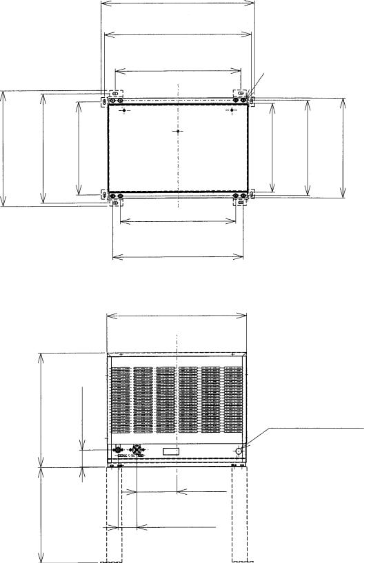
4. CONDENSER UNIT
URC-6F
18-1/8" (460 mm.) |
17-1/8" (435 mm.) |
14-9/16" (370 mm.) |
17-7/8" (454 mm.) |
2-1/2" (63 mm.) |
14-15/16" (380 mm.)
24" (610 mm.)
23-1/32"
(585 mm.)
19-11/16" |
6/16" x 3/4" (10 mm. x 20 mm.) |
(500 mm.) |
4 x 2 (SLOTTED HOLES) |
14-1/8" (358 mm.) |
14-15/16" (380 mm.) |
15-11/16" (398 mm.) |
18-1/8"
(460 mm.)
20-15/32"
(520 mm.)
21-15/16"
(557 mm.)
7/8" DIA. HOLE (23 mm. DIA.)
6-5/16"
(160 mm.)
2-15/16"
(75 mm.)
9

SPECIFICATIONS
MODEL: URC-6F
EXTERIOR
DIMENSIONS (W x D x H)
REFRIGERANT CHARGE
WEIGHT
CONNECTIONS
REFRIGERANT
ELECTRICAL
CONDENSER
HEAD PRESSURE CONTROL
AMBIENT CONDITION
Galvanized Steel
21-15/16" x 15-11/16" x 17-7/8" (557 x 398 x 453.8 mm.)
R404A 1 lb. 2 oz. (505 g)
Net 61 lbs. (28 kg)
Shipping 68 lbs. (31 kg)
One Shot Couplings (Aeroquip)
Permanent Connection
Air-cooled
Condensing Pressure Regulator
Min. -20°F - Max. +122°F (-29°C to +50°C) Outdoor use
10
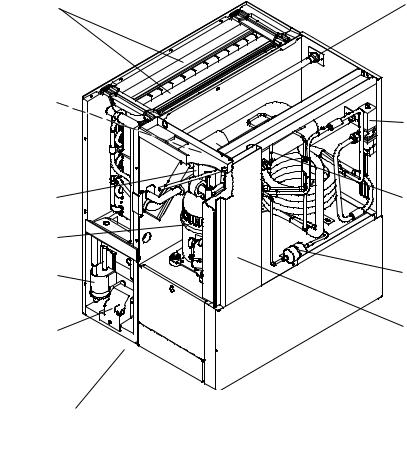
II.GENERAL INFORMATION
1.CONSTRUCTION
[a]KM-500MAH
Spray Tubes
Control Switch
Bin Control Thermostat
(except models with
Mechanical Bin Control) 


 Expansion Valve


Compressor
Float Switch
Water Pump
Mechanical
Bin Control (except models with Thermostat)
Water Supply Inlet
Condenser
Hot Gas Valve
Fan Motor
Condenser
Drier
Control Box
11
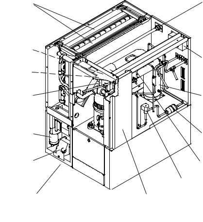
[b] KM-500MWH
Spray Tubes |
Water Supply Inlet |
Control Switch


 Water Regulator Bin Control Thermostat

(except models with  Mechanical Bin Control)
Expansion Valve |
Hot Gas Valve |
Compressor |
|
Float Switch |
Drier |
Water Pump |
Control Box |
Mechanical
Bin Control
(except models with Thermostat)
12
[c] KM-500MRH
Spray Tubes
Control Switch
Bin Control Thermostat  (except models with
  Mechanical Bin Control)
Expansion Valve
Compressor 
Float Switch
Water Pump
Mechanical
Bin Control
(except models with Thermostat)
Water Supply Inlet
Junction Box
Receiver Tank
Drier
Hot Gas Valve
Line Valve
Control Box
13

2. CONTROLLER BOARD
[a] SOLID-STATE CONTROL
1)A HOSHIZAKI exclusive solid-state control is employed in Modular Crescent Cubers.
2)A Printed Circuit Board (hereafter called “Controller Board”) includes a stable and high quality control system.
3)All models are pretested and factory-adjusted.
[b] CONTROLLER BOARD
CAUTION
1.Fragile, handle very carefully.
2.A controller board contains integrated circuits, which are susceptible to failure due to static discharge. It is especially important to touch the metal part of the unit when handling or replacing the board.
3.Do not touch the electronic devices on the board or the back of the board to prevent damage to the board.
4.Do not change wiring and connections. Do not misconnect K3, K4 and K5, because the same connector is used for the Thermistor (white), Float Switch (black), and Mechanical Bin Control (red).
(For machines with thermostat, there is no connection on K4.)
5.Always replace the whole board assembly when it goes bad.
6.Do not short out power supply to test for voltage.
PART NUMBER |
TYPE |
2A1410-01 |
HOS-001A (Control Products) |
Features of Control Products “E” Controller Board
1) Maximum Water Supply Period - 6 minutes
Water Solenoid Valve opening, in the Defrost (Harvest) Cycle, is limited by the defrost timer. The Water Valve cannot remain open longer than the
maximum period. The Water Valve can close in less than six minutes if the defrost cycle is completed.
14
2)Defrost Timer
The defrost cycle starts when the Float Switch opens and completes the freeze cycle.
But the Defrost Timer does not start counting until the Thermistor senses 48°F at the
Evaporator outlet. The period from the end of the freeze cycle up to the point of the
Thermistor's sensing varies depending on the ambient and water temperatures.
3)High Temperature Safety - 127 ± 7°F
The temperature of the suction line in the refrigerant circuit is limited by the High
Temperature Safety.
During the defrost cycle the Evaporator temperature rises. The Thermistor senses 48°F and starts the Defrost Timer. After the Defrost Timer counts down to zero, the normal freeze cycle begins. If the Evaporator temperature continues to rise, the Thermistor will sense the rise in temperature and at 127 ± 7°F the Thermistor operates the High Temperature Safety.
This High Temperature Safety shuts down the circuit and the icemaker automatically stops.
This High Temperature Safety protects the unit from excessive temperature. The Control
Board will Beep every 3 seconds. The white Reset Button on the Control Board must be pressed with power on to reset the Safety.
4)Low Water Safety
If the Pump Motor is operated without water, the mechanical seal can fail. To prevent this type of failure, the Controller Board checks the position of the Float Switch at the end of the initial one minute water fill cycle and at the end of each defrost cycle.
If the Float Switch is in the up position (electrical circuit closed), the Controller Board changes to the ice making cycle. If the Float Switch is in the down position (electrical circuit open), the Controller Board changes to a one minute water fill cycle before starting the ice making cycle. This method allows for a Low Water Safety shut down to protect the
Water Pump from mechanical seal failure.
For water-cooled model, if the water is shut off, the unit is protected by the High Pressure Switch.
5)High Voltage Cutout
The maximum allowable supply voltage of this icemaker is limited by the High Voltage Cutout.
If miswiring (especially on single phase 3 wire models) causes excessive voltage on the
Controller Board, the High Voltage Cutout shuts down the circuit in 3 seconds and the icemaker automatically stops. When the proper supply voltage is resumed, the icemaker automatically starts running again. The Control Board will signal this problem using 7 Beeps every 3 seconds.
6)LED Lights and Audible Alarm Safeties
The red LED indicates proper control voltage and will remain on unless a control voltage problem occurs. At startup a 5 second delay occurs while the board conducts an internal timer check. A short beep occurs when the power switch is turned ON or OFF.
15

The green LED’s 1-4 represent the corresponding relays and energize and sequence 5 seconds from initial start-up as follows:
Sequence Step |
LED’s on Length: |
Min. |
Max. |
Avg. |
1 Minute Fill Cycle |
LED4 |
|
|
60 sec. |
Harvest Cycle |
LED1, 4, & 2 |
2 min. |
20 min. |
3-5 min. |
Freeze Cycle |
LED1 |
5 min. |
60 min. |
30-35 min. |
Reverse Pump Out |
LED1, 3, & 2 |
10 sec. |
20 sec. |
Factory set. |
{LED 1 – Comp; LED 2 - HGV/CFM; LED 3 – PM; |
LED 4 - WV} |
|
||
The built in safeties shut down the unit and have alarms as follows:
1 beep every 3 sec. = High Evaporator Temperature >127 ° F.
Check for defrost problem (stuck HGV or relay), hot water entering unit, stuck headmaster, or shorted thermistor.
2 beeps every 3 sec. = Defrost Back Up Timer. Defrost >20 minutes. Orange LED marked 20 MIN energizes.
Check for open thermistor, HGV not opening, TXV leaking by, low charge, or inefficient compressor.
3 beeps every 3 sec. = Freeze Back Up Timer. Freeze > 60 minutes. Yellow LED marked 60 MIN energizes.
Check for F/S stuck closed (up), WV leaking by, HGV leaking by, TXV not feeding properly, low charge, or inefficient compressor.
Machines with mechanical bin control ONLY
4 beeps every 3 sec. = Short Circuit between the K4 connection on the control board and the bin control relay. Check connections and replace wire harness if necessary.
5 beeps every 3 sec. = Open Circuit between the K4 connection
on the control board and the bin control relay. Check connections and replace wire harness if necessary.
To manually reset the above safeties, depress white alarm reset button with the power supply ON.
6 beeps every 3 sec. = Low Voltage. Voltage is 92 Vac or less.
7 beeps every 3 sec. = High Voltage. Control voltage > 147 Vac ±5%.
The red LED will de-energize if voltage protection operates.
The voltage safety automatically resets when voltage is corrected.
The Output Test switch “S3” provides a relay sequence test. With power OFF, place S3
ON and switch power to ICE. The correct lighting sequence should be none, 2, 3, 4, 1, & 4, normal sequence every 5 seconds. S3 should remain in the “OFF” position for normal operation.
16

The application switch located between relay X3 & X4 must be set to match the original board application. Place this switch in the ALP position if there is no white wire supplied to the K1 connector. If there is a white wire, place the switch in the C position. If this switch is placed in the wrong position, either the compressor contactor will remain energized with the control switch OFF, or the unit will not start.
The dip switches should be adjusted per the adjustment chart published in the Tech Specs book. Number 8 must remain in the OFF position.
(Control Products HOS-001A Board)
17
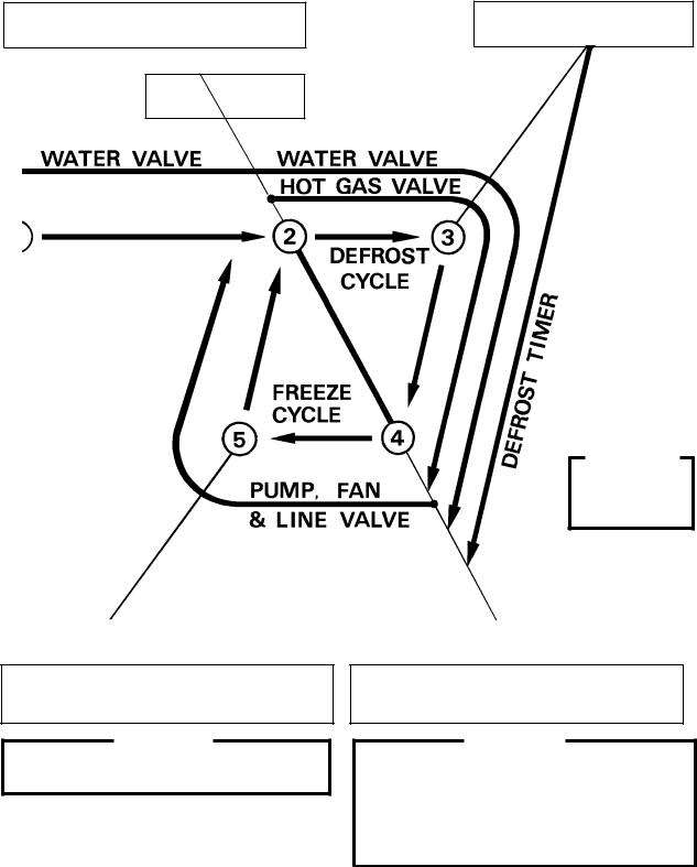
[c] SEQUENCE
1st Cycle
1.Unit energized and Control Switch to “ICE” position. Water supply cycle starts.
3.Thermistor reads 48° F. Defrost Timer starts counting.
2.After 1 minute, Defrost cycle starts.
IMPORTANT
Water Valve opening is limited to 6 minutes.
 &
&
5.After the first 5 minutes in freeze cycle. Ready to complete freeze cycle when Float Switch circuit opens.
IMPORTANT
Board never accepts freeze completion signal within the first 5 minutes in freeze cycle.
4.Defrost Timer stops counting.
Defrost cycle is completed and freeze cycle starts.
IMPORTANT
1.Board never accepts defrost completion signal within the first 2 minutes in defrost cycle.
2.Defrost cycle time is limited to 20 minutes even if Defrost Timer does not stop counting.
18
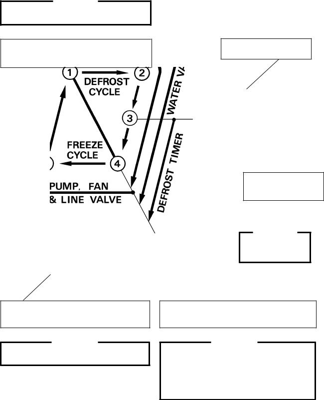
2nd Cycle and after with pump drain
IMPORTANT
Freeze cycle time is limited to 60 minutes even if Float Switch does not open.
1.Float Switch opens and signals to complete freeze cycle.
Drain timer starts counting.
2.Drain timer stops counting. Pump drain is completed
3.Thermistor reads 48° F. Defrost Timer starts counting.
 &
&
5.After the first 5 minutes in freeze cycle. Ready to complete freeze cycle when Float Switch circuit opens.
IMPORTANT
Board never accepts freeze completion signal within the first 5 minutes in freeze cycle.
IMPORTANT
Water Valve
opening is limited to 6 minutes.
4.Defrost Timer stops counting.
Defrost cycle is completed and freeze cycle starts.
IMPORTANT
1.Board never accepts defrost completion signal within the first 2 minutes in defrost cycle.
2.Defrost cycle time is limited to 20 minutes even if Defrost Timer does not stop counting.
19
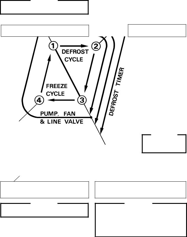
2nd Cycle and after with no pump drain
IMPORTANT
Freeze cycle time is limited to 60 minutes even if Float Switch does not open.
1.Float Switch opens and signals to complete freeze cycle.
 &
&
4.After the first 5 minutes in freeze cycle. Ready to complete freeze cycle when Float Switch circuit opens.
IMPORTANT
Board never accepts freeze completion signal within the first 5 minutes in freeze cycle.
2.Thermistor reads 48° F. Defrost Timer starts counting.
IMPORTANT
Water Valve
opening is limited to 6 minutes.
3.Defrost Timer stops counting.
Defrost cycle is completed and freeze cycle starts.
IMPORTANT
1.Board never accepts defrost completion signal within the first 2 minutes in defrost cycle.
2.Defrost cycle time is limited to 20 minutes even if Defrost Timer does not stop counting.
20
[d] CONTROLS AND ADJUSTMENTS
The Dip Switch is factory-adjusted to the following positions:
FOR MODELS WITH MECHANICAL BIN CONTROL:
DIP SWITCH NO. |
1 |
2 |
3 |
4 |
5 |
6 |
7 |
8 |
9 |
10 |
|
KML-500MAH |
OFF |
OFF |
OFF |
OFF |
ON |
ON |
ON |
OFF |
ON |
OFF |
|
|
|
|
|
|
|
|
|
|
|
|
|
KML-500MWH |
OFF |
OFF |
OFF |
OFF |
ON |
ON |
ON |
OFF |
OFF |
OFF |
|
KML-500MRH |
OFF |
OFF |
OFF |
OFF |
ON |
ON |
ON |
OFF |
OFF |
OFF |
|
|
|
|
|
|
|
|
|
|
|
|
|
FOR MODELS WITH THERMOSTAT :
DIP SWITCH NO. |
1 |
2 |
3 |
4 |
5 |
6 |
7 |
8 |
9 |
10 |
|
KML-500MAH |
OFF |
OFF |
OFF |
OFF |
ON |
ON |
OFF |
OFF |
ON |
OFF |
|
|
|
|
|
|
|
|
|
|
|
|
|
KML-500MWH |
OFF |
OFF |
OFF |
OFF |
ON |
ON |
OFF |
OFF |
OFF |
OFF |
|
KML-500MRH |
OFF |
OFF |
OFF |
OFF |
ON |
ON |
OFF |
OFF |
OFF |
OFF |
|
|
|
|
|
|
|
|
|
|
|
|
|
Switch Nos. 1 and 2:
Used for adjustment of the Defrost Timer.
The Defrost Timer starts counting when the Thermistor reads a certain temperature at the Evaporator outlet.
Switch Nos. 3 and 4:
Used for adjustment of the Drain Timer.
When a freeze cycle is completed, the Pump Motor stops, and the icemaker resumes operation in 2 seconds. Then the Pump Motor drains the Water Tank for the time determined by the Drain Timer. The Drain Timer also determines the time to restrain completion of a defrost cycle, i.e. the minimum defrost time.
Switch Nos. 5 and 6:
Used for adjustment of the Drain Counter.
The Pump Motor drains the Water Tank at the frequency determined by the Drain
Counter.
Switch No. 7:
Used only on models with mechanical bin control. Dip Switch should be set “ON”.
(Models with bin thermostat, Switch No. 7 should be set in the “OFF” position.)
Switch No. 8:
Used only for checking the Controller Board. Usually set in OFF position.
21
 Loading...