


CRES49
Table of contents
 Loading...
Hoshizaki CRES49, CPT93, CPT67, CRES60, CRES36 User Manual
...
Hoshizaki
“A Superior Degree
of Reliability”
www.hoshizaki.com
Models
Refrigerated Prep Table with Raised Rail
Refrigerated Equipment Stand
Commercial Series
Refrigerated Kitchen Equipment
Hoshizaki America, Inc.
Number: 73206
Issued: 6-2-2015
Revised: 12-1-2015
SERVICE MANUAL
2
WARNING
Only qualied service technicians should install and service the appliance. To
obtain the name and phone number of your local Hoshizaki Certied Service
Representative, visit www.hoshizaki.com. No service should be undertaken until
the technician has thoroughly read this Service Manual. Failure to service and
maintain the appliance in accordance with this manual will adversely affect safety,
performance, component life, and warranty coverage. Proper installation is the
responsibility of the installer. Product failure or property damage due to improper
installation is not covered under warranty.
Hoshizaki provides this manual primarily to assist qualied service technicians in the
service of the appliance.
Should the reader have any questions or concerns which have not been satisfactorily
addressed, please call, send an e-mail message, or write to the Hoshizaki Technical
Support Department for assistance.
Phone: 1-800-233-1940; (770) 487-2331
Fax: 1-800-843-1056; (770) 487-3360
E-mail: techsupport@hoshizaki.com
HOSHIZAKI AMERICA, INC.
618 Highway 74 South
Peachtree City, GA 30269
Attn: Hoshizaki Technical Support Department
Web Site: www.hoshizaki.com
NOTE: To expedite assistance, all correspondence/communication MUST include the
following information:
• Model Number
• Serial Number
• Complete and detailed explanation of the problem.

3
IMPORTANT
This manual should be read carefully before the appliance is serviced. Read
the warnings and guidelines contained in this booklet carefully as they provide
essential information for the continued safe use, service, and maintenance of the
appliance. Retain this booklet for any further reference that may be necessary.
CONTENTS
Important Safety Information ................................................................................................. 4
I. Construction and Refrigeration Circuit Diagram ................................................................. 8
A. Construction .................................................................................................................. 8
1. CPT .......................................................................................................................... 8
2. CRES ....................................................................................................................... 9
B. Refrigeration Circuit Diagram ...................................................................................... 10
II. Sequence of Operation and Service Diagnosis ................................................................11
A. Sequence of Operation Flow Chart ..............................................................................11
B. Service Diagnosis ....................................................................................................... 12
C. Thermistor Check ........................................................................................................ 16
D. Diagnostic Table .......................................................................................................... 17
III. Controls and Adjustments .............................................................................................. 19
A. Control Module ............................................................................................................ 19
B. Temperature ................................................................................................................ 21
1. Default Temperature Settings ................................................................................. 21
2. Temperature Setpoint ............................................................................................ 21
3. Changing the Temperature Display Scale (°F or °C) ............................................. 21
C. Manual Defrost ............................................................................................................ 21
D. Alarm Safeties ............................................................................................................. 22
E. Safety Devices ............................................................................................................ 22
IV. Refrigeration Circuit and Component Service Information.............................................. 23
A. Refrigeration Circuit Service Information .................................................................... 23
1. Refrigerant Recovery ............................................................................................. 23
2. Brazing .................................................................................................................. 24
3. Evacuation and Recharge (R-134a) ...................................................................... 24
B. Component Service Information .................................................................................. 25
C. CPT Door Reversal ..................................................................................................... 26
V. Maintenance .................................................................................................................... 29
VI. Preparing the Appliance for Periods of Non-Use ............................................................ 30
VII. Disposal ......................................................................................................................... 31
VIII. Technical Information .................................................................................................... 32
A. Electrical and Refrigerant Data ................................................................................... 32
B. Wiring Diagrams .......................................................................................................... 33
1. CPT46(-D), CPT67(-D), CPT93(-D) ....................................................................... 33
2. CRES36, CRES49, CRES72, CRES85, CRES98 ................................................. 34
4
Important Safety Information
Throughout this manual, notices appear to bring your attention to situations which could
result in death, serious injury, damage to the appliance, or damage to property.
WARNING Indicates a hazardous situation which could result in death or
serious injury.
NOTICE Indicates a situation which could result in damage to the
appliance or property.
IMPORTANT Indicates important information about the use and care of the
appliance.
WARNING
The appliance should be destined only to the use for which it has been expressly
conceived. Any other use should be considered improper and therefore dangerous.
The manufacturer cannot be held responsible for injury or damage resulting from
improper, incorrect, and unreasonable use. Failure to service and maintain the
appliance in accordance with this manual will adversely affect safety, performance,
component life, and warranty coverage.
To reduce the risk of death, electric shock, serious injury, or re, follow basic
precautions including the following:
• Only qualied service technicians should install and service the appliance.
• The appliance must be installed in accordance with applicable national, state, and
local codes and regulations. Failure to meet these code requirements could result
in death, electric shock, serious injury, re, or damage to the appliance.
• Appliance is heavy. Use care when lifting or positioning. Work in pairs when
needed to prevent injury or damage. Do not lift using the refrigeration area, the
top section, or the doors/drawers.
• To reduce the risk of electric shock, do not touch the plug with damp hands.
• Unplug the appliance before servicing.
• The appliance requires an independent power supply of proper capacity. See
the nameplate for electrical specications. Failure to use an independent power
supply of proper capacity can result in a tripped breaker, blown fuse, damage to
existing wiring, or component failure. This could lead to heat generation or re.
• THE APPLIANCE MUST BE GROUNDED. The appliance is equipped with a
NEMA5-15 three-prong grounding plug
to reduce the risk of potential shock
hazards. It must be plugged into a properly grounded, independent 3-prong wall
outlet. If the outlet is a 2-prong outlet, it is your personal responsibility to have a
qualied electrician replace it with a properly grounded, independent 3-prong wall
outlet. Do not remove the ground prong from the plug and do not use an adapter
plug. Failure to follow these instructions may result in death, electric shock, or re.
• The GREEN ground wire in the factory-installed power cord is connected to the
appliance. If it becomes necessary to remove or replace the power cord, be sure
to connect the power cord's ground wire.
• Do not use an extension cord.

5
WARNING, continued
• Do not use an appliance with a damaged power cord. The power cord should not
be altered, jerked, bundled, weighed down, pinched, or tangled. Such actions could
result in electric shock or re. To unplug the appliance, be sure to pull the plug, not
the cord, and do not jerk the cord.
• Do not splash, pour, or spray water directly onto or into the appliance. This might
cause short circuit, electric shock, corrosion, or failure.
• Do not make any alterations to the appliance. Alterations could result in electric
shock, injury, re, or damage to the appliance.
• The appliance is not intended for use by persons (including children) with reduced
physical, sensory, or mental capabilities, or lack of experience and knowledge,
unless they have been given supervision or instruction concerning use of the
appliance by a person responsible for their safety.
• Children should be properly supervised around the appliance.
• Do not climb, stand, or hang on the appliance or doors/drawers or allow children or
animals to do so. Do not climb into the appliance or allow children or animals to do
so. Death or serious injury could occur or the appliance could be damaged.
• Be careful not to pinch ngers when opening and closing the doors/drawers or rail
cover. Be careful when opening and closing the doors/drawers or rail cover when
children are in the area.
• Open and close the doors/drawers and rail cover with care. Opening the doors/
drawers or rail cover too quickly or forcefully may cause injury or damage to the
appliance or surrounding equipment.
• Do not use combustible spray or place volatile or ammable substances in or near
the appliance. They might catch re.
• Keep the area around the appliance clean. Dirt, dust, or insects in the appliance
could cause harm to individuals or damage to the equipment.
• The appliance is designed only for temporary storage of food. Employ sanitary
methods. Use for any other purposes (for example, storage of chemicals or medical
supplies such as vaccine and serum) could cause deterioration of stored items.
• Do not block air inlets or outlets, otherwise cooling performance may be reduced.
• Do not tightly pack the cabinet. Allow some space between items to ensure good air
ow. Also allow space between items and interior surfaces.
• Do not put warm or hot foods in the cabinet. Let them cool rst, or they will raise the
cabinet temperature and could deteriorate other foods in the cabinet or overload
the appliance.
• All foods should be wrapped in plastic lm or stored in sealed containers.
Otherwise, foods may dry up, pass their smells onto other foods, cause frost
to develop, result in poor appliance performance, or increase the likelihood of
cross-contamination. Certain dressings and food ingredients, if not stored in sealed
containers, may accelerate corrosion of the evaporator, resulting in failure.
• Do not store items near air outlets. Otherwise, items may freeze up and crack or
break causing a risk of injury or contamination of other food.
6
WARNING, continued
CPT Models
• Do not throw anything onto the shelves or load any single shelf with more than
120lb. (54.5 kg) of product. They might fall off and cause injury.
• Do not load any single drawer with more than 150 lb. (68 kg) of product. Depending
on the weight of product in the drawers, secure the unit as necessary to prevent it
from overturning. Do not open more than one drawer at a time.
• The entire rail must always be covered by rail dividers and pans. Otherwise, the
appliance will not cool properly. Use only pans up to 6" (15 cm) deep. Do not use
damaged rail dividers or pans.
• Ingredients must be pre-chilled to 37°F (3°C) or less before placing in rail.
• Keep the rail cover closed when not actively preparing food.
• The rail is for keeping ingredients cool while preparing food. If not actively preparing
food for a long period such as overnight, seal pans with plastic wrap in addition
to closing the rail cover. Depending on conditions, the cabinet temperature
setting may need to be adjusted to prevent items from freezing. Alternatively, seal
ingredients and store them in a refrigerator or freezer.
• For CPT46(-D) models, the anti-tip bracket must be properly installed and adjusted.
Otherwise, the unit may tip resulting in injury or damage.
CRES Models
• A minimum of 4" (11 cm) clearance is required between the bottom of the cooking
equipment heating element and the appliance top. When setting up cooking
equipment, follow the cooking equipment manufacturer's setup procedure.
Temperature at the appliance top must not exceed 180°F (82°C). For optimum
performance, installation of a heat shield (supplied by others) is recommended.
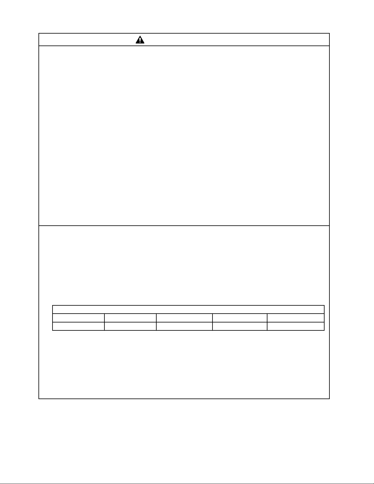
• For cooking equipment on the cabinet, do not exceed the total maximum weight
listed for your model.
Total Maximum Weight for Cooking Equipment on the Cabinet
CRES36 CRES49 CRES72 CRES85 CRES98
700 lb. (318 kg) 700 lb. (318 kg) 1,200 lb. (544 kg) 1,200 lb. (544 kg) 1,500 lb. (680 kg)
• Do not load any single drawer with more than 75 lb. (34 kg) of product. Depending
on the weight of product in the drawers, secure the unit as necessary to prevent it
from overturning. Do not open more than one drawer at a time.
• All casters on the appliance are lockable. After positioning the appliance in its nal
location, lock all casters.
• Before servicing or cleaning the appliance, disconnect any cooking equipment on
the appliance top and allow to cool.

7
NOTICE
• Protect the oor when moving the appliance to prevent damage to the oor.
• Keep ventilation openings, in the appliance enclosure or in the built-in structure,
clear of obstruction. The factory-installed rear bumpers must be in place to ensure
proper rear clearance. Blockage of airow could negatively affect performance and
damage the appliance.
• To prevent deformation or cracks, do not spray insecticide onto the plastic parts or
let them come into contact with oil.
• To avoid damage to the gasket, use only the door/drawer handle when opening and
closing.
• Do not leave the doors/drawers open.
• To avoid damage to the top seal, do not lift the appliance by the top section or
remove the top section.
Additional Notice for CPT Models
• Do not allow the appliance to bear any outside weight.
• Do not place anything on top of the rail cover and do not lift the appliance by the rail
cover. The rail cover is not designed to bear any outside weight.
• Do not place anything on the air duct panels beneath the pans in the rail. The air
duct panels are not load-bearing.
8
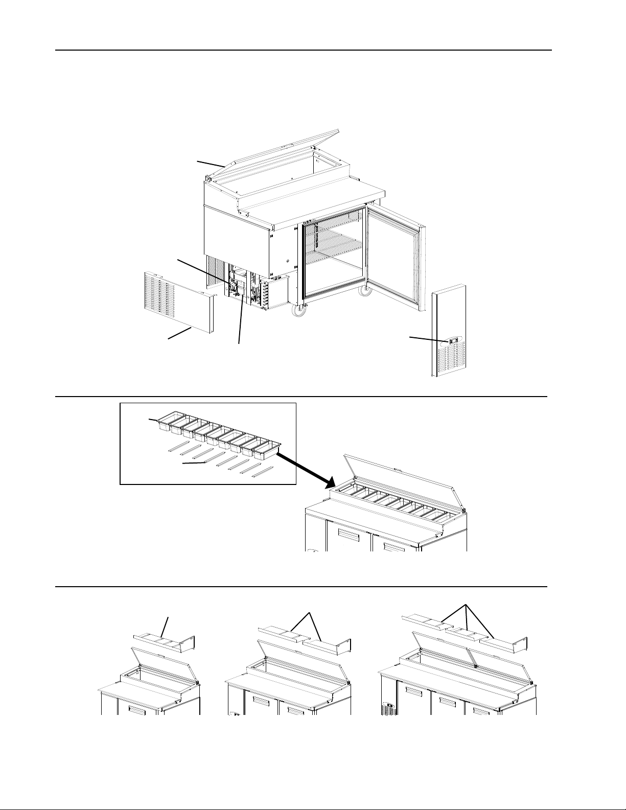
I. Construction and Refrigeration Circuit Diagram
A. Construction
1. CPT
Left Side Panel
Front Panel
Rail Cover
Control
Module
Model Shown: CPT46
Compressor
Air Duct Panels
Air Duct Panels
Air Duct Panel
CPT46 Series CPT67 Series CPT93 Series
Pans
Rail Dividers
Model Shown: CPT67
Start Relay and
Start Capacitor
9
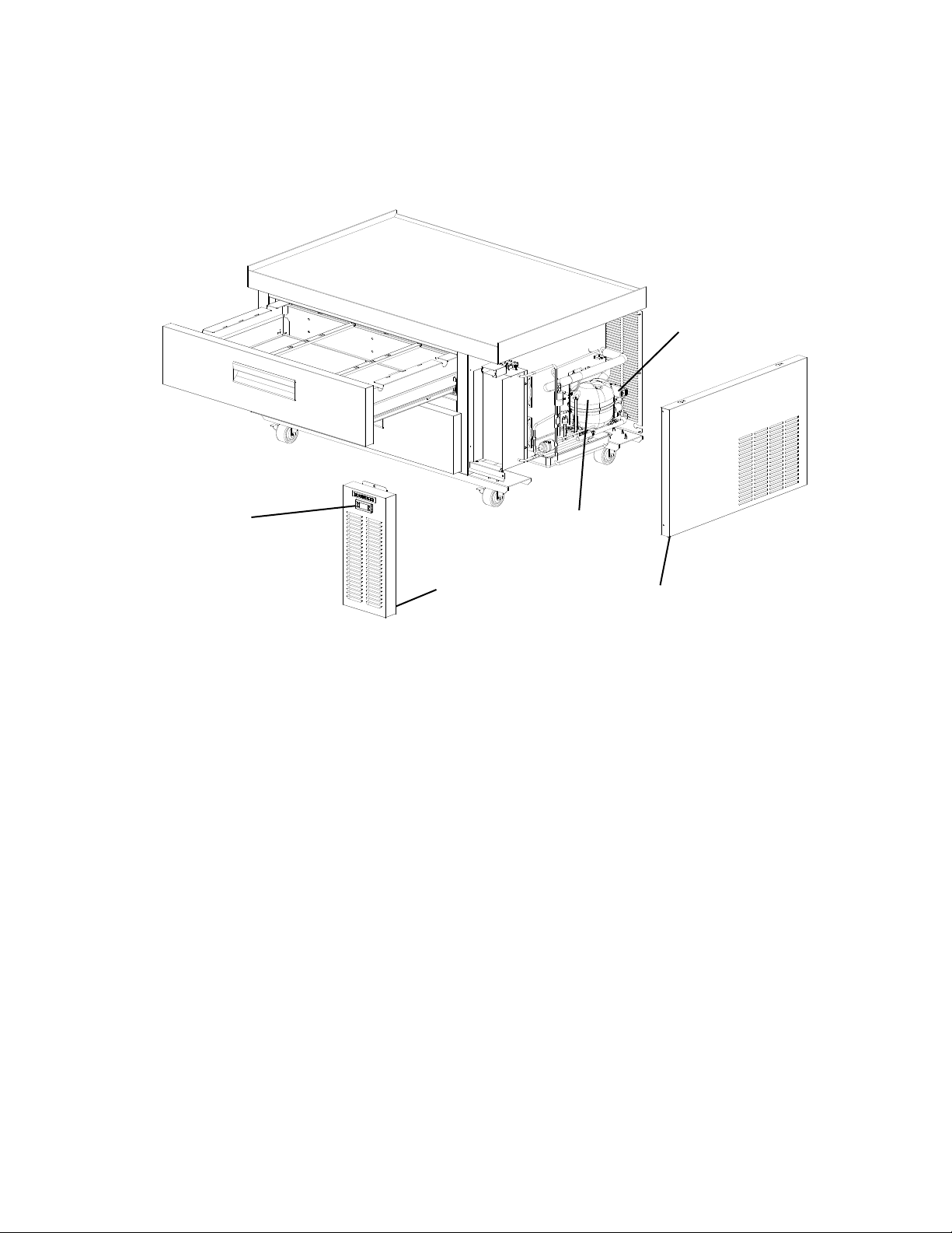
2. CRES
Right Side Panel
Front Panel
Control Module
Compressor
Start Relay and
Start Capacitor
Model Shown: CRES49

10
B. Refrigeration Circuit Diagram
1. CPT and CRES Models
Evaporator Fans
(quantity depends on model)
Evaporator
Compressor
Drier
Condenser
Defrost Heater
Capillary Tube
High-Pressure Switch
(CPT67(-D), CPT93(-D)),
and All CRES Models)
Defrost Safety
Thermostat
Condenser Fan(s)
(quantity depends
on model)
11
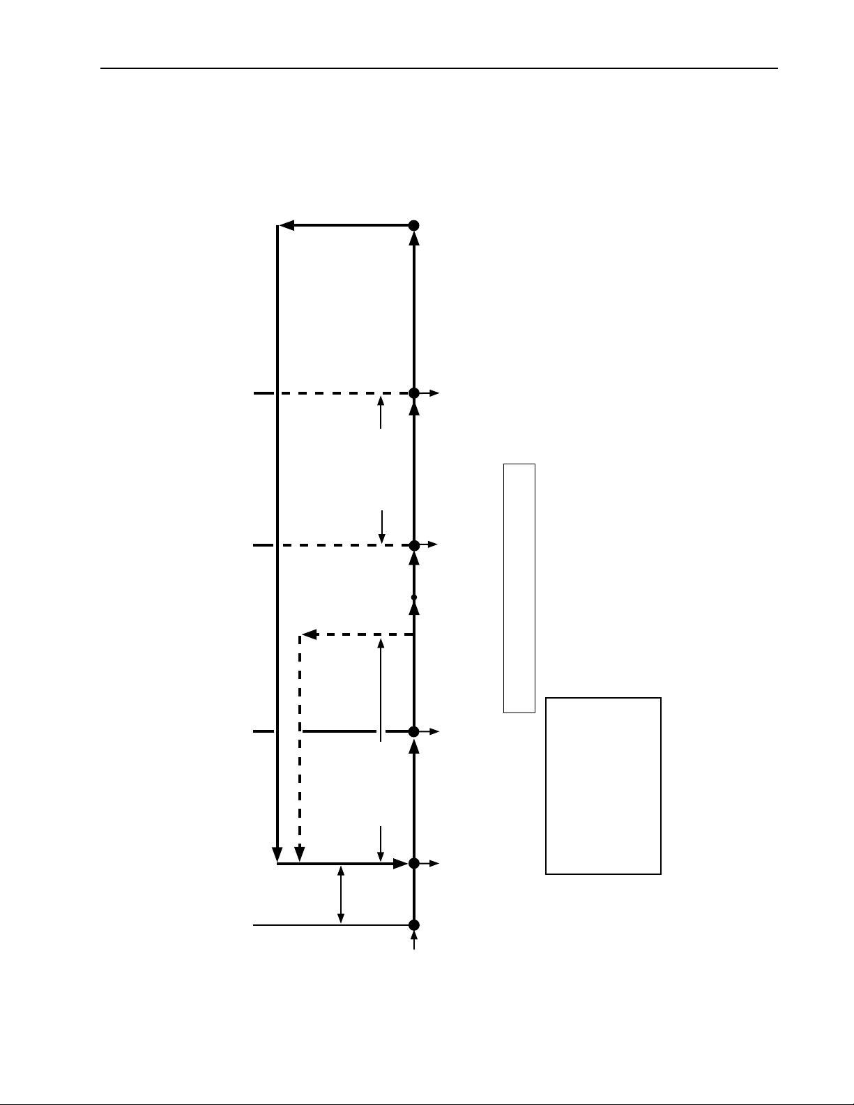
II. Sequence of Operation and Service Diagnosis
A. Sequence of Operation Flow Chart
DTh warms to 41°F (5°C)
1-min. Comp/CPT EvapFM
delay timer starts
11-min. temperature display
delay timer starts
3. Cool Down Restart
CPT and CRES Sequence Flow Chart
Legend:
Comp-compressor
ConFM-condenser fan motor
CTh-cabinet thermistor
DH-defrost heater
DTh-defrost thermistor
EvapFM-evaporator fan motor
1. Startup/Cool Down
2. Cool Down Achieved
Comp energized
ConFM energized
EvapFM energized
CTh in control
Slight
Delay at
Startup
CTh cools
to 3°F (1.7°C)
below setpoint.
*See Table.
CTh warms
to 3°F (1.7°C)
above setpoint
4. Defrost Initiation
EvapFM continues
Comp de-energized
ConFM de-energized
5. Defrost Termination
Note:
a) 2-min. minimum Comp on timer starts when Comp energizes.
b) 2-min. minimum Comp off timer starts when Comp de-energizes.
c) 5-min. minimum defrost time.
d) 1-hr. maximum defrost time.
e) "dEF" displayed during defrost.
DTh in control
DH energized
Comp de-energized
ConFM de-energized
EvapFM de-energized
2-min. Comp off
timer starts
2-min. Comp on
timer starts
Comp energized
ConFM energized
CRES EvapFM energized
CPT EvapFM energized (DTh≤36°F(2°C))
DH de-energized
Startup
DTh is at or below
39°F (3.8°C) and
6-hr. defrost interval timer
terminates
*CPT: Factory Default Setpoint 32°F (0°C)
*CRES: Factory Default Setpoint 35°F (2°C)
Loading...