

AM SERVICE TRAINING
Featuring the
AM-50BAE, AM -100BAE, AM-150BAF
AM-50BAE
AM-100BAE AM-150BAF
80047 www.hoshizakiamerica.com 5-20-04
25mm
All AM models have similar sequence of operation. This manual is designed as a
generic AM Training manual.
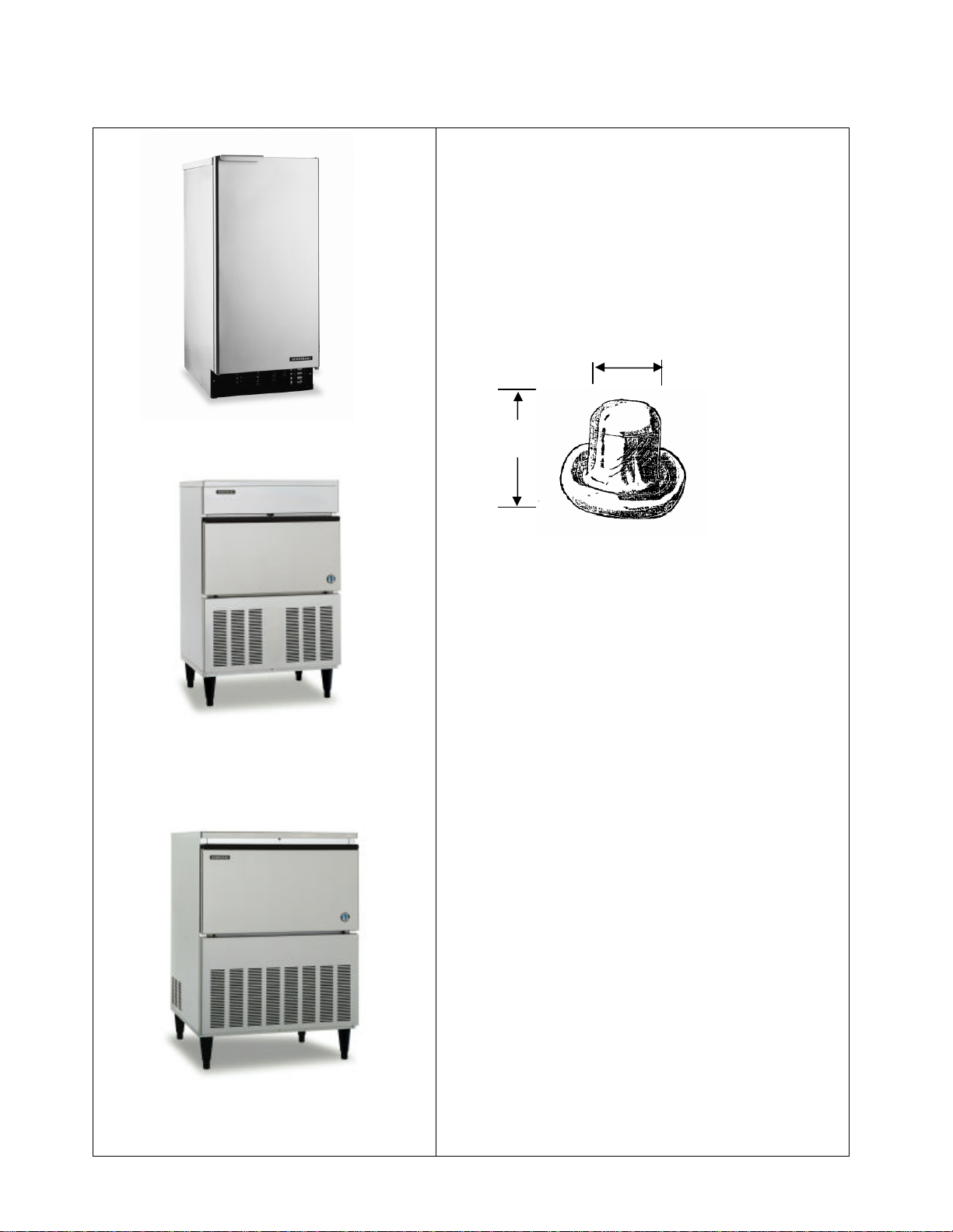
The Hoshizaki AM series ice machine uses a
horizontal evaporator design which forms a
unique cube shape.
20mm
The compact AM-50BAE unit is 14 7/8”w x
22 5/8”d x 33 1/2”h and is designed for
counter-top, under-counter, or freestanding
installations with up to 51 pounds of
production and 30 pounds of storage
The AM-100 and AM-150 are for under
counter or free standing applications .
The AM-100 dimensions are 24 15/16”w x
20 1/2”d x 39”h with 6” legs and can
produce up to 105 and pounds with 44
pounds of storage.
The AM150 measures 27 11/16”w x 27
15/16”d x 39”h with 6” legs and production
up to 150 pounds with 88 pounds of storage.
- 2 -
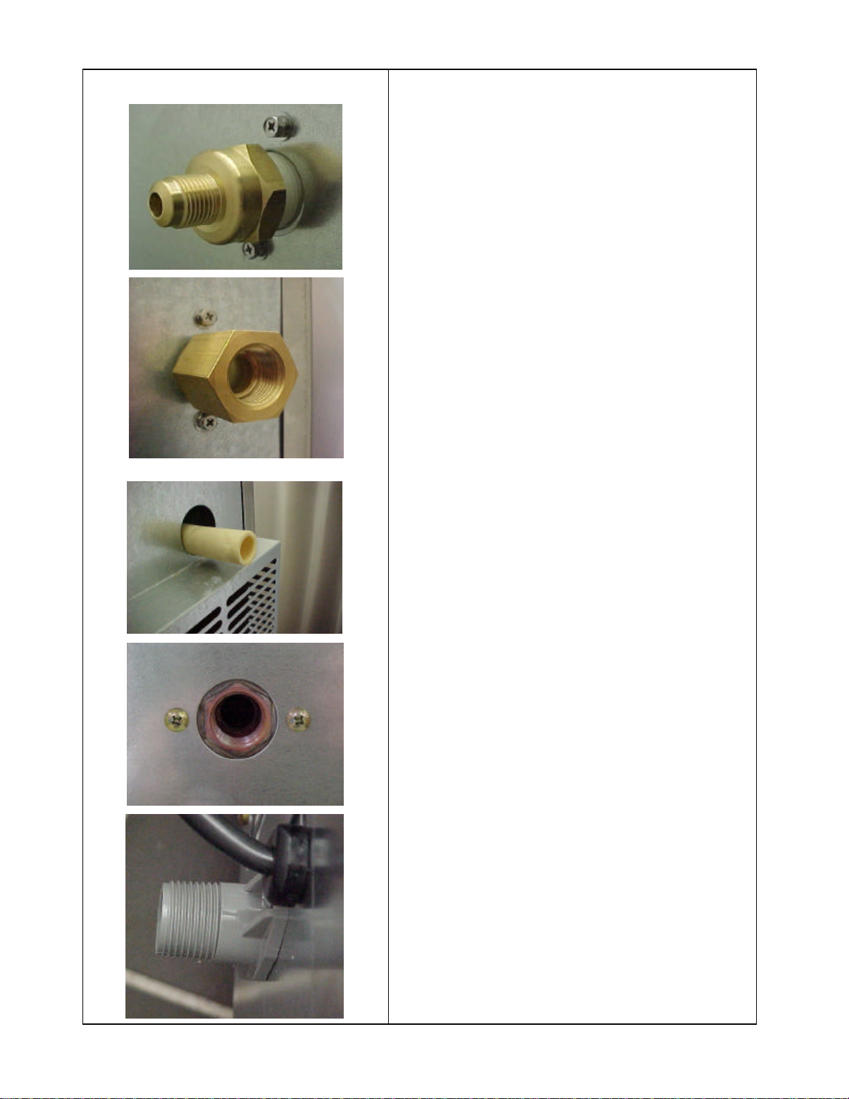
DRAIN
CONNECTIONS
4A32
40-01 1/2” FPT
1/2” FPT
5/8” I.D. rubber hose
WATER INLET CONNECTIONS
3/8” Male flare
4A3207-01
(AM-50 through April
2004)
AM-50 from May 2004
3/4” MPT
(AM-100 & AM-150)
A standard 120-volt power cord provides the
electrical connection. The unit is designed to
operate on a separate 15-amp circuit.
Inlet Water Line Connection
• 1st production units had a 3/4" BSP
connection directly to the inlet water
valve. (DO not connect with 3/4" FIP)
• Fitting (4A3207-01) and gasket
413854-01 were used from May
through July production. (Through
August on the AM -100BAE and AM150 BAF)
• Fitting (4A3240-01) and gasket
413854-01 were added in August 03
on the AM-50BAE and September 03
on the AM-100BAE and AM150BAF.
If no fitting is included, order either fitting
/gasket above or use 3/4" hose type fitting to
make this connection.
A minimum 3/8” water line is required for
proper operation.
Drain line connection
The drain connection for the AM-50 was
5/8” I.D. hose until April of 2004 and was
located on the left rear of the unit. A
standard 3/4” male insert fitting can be used
to connect this drain. From May 2004 the
drain fitting is 1/2” FPT. A minimum 1/2”
I.D. vented drain is required when making
this connection.
The drain for the AM-100 and AM-150 is a
3/4” MPT.
Since the unit will likely be enclosed, it is
recommended to use flexible, supply and
drain connections. This will allow easy
removal if service is necessary.
- 3 -
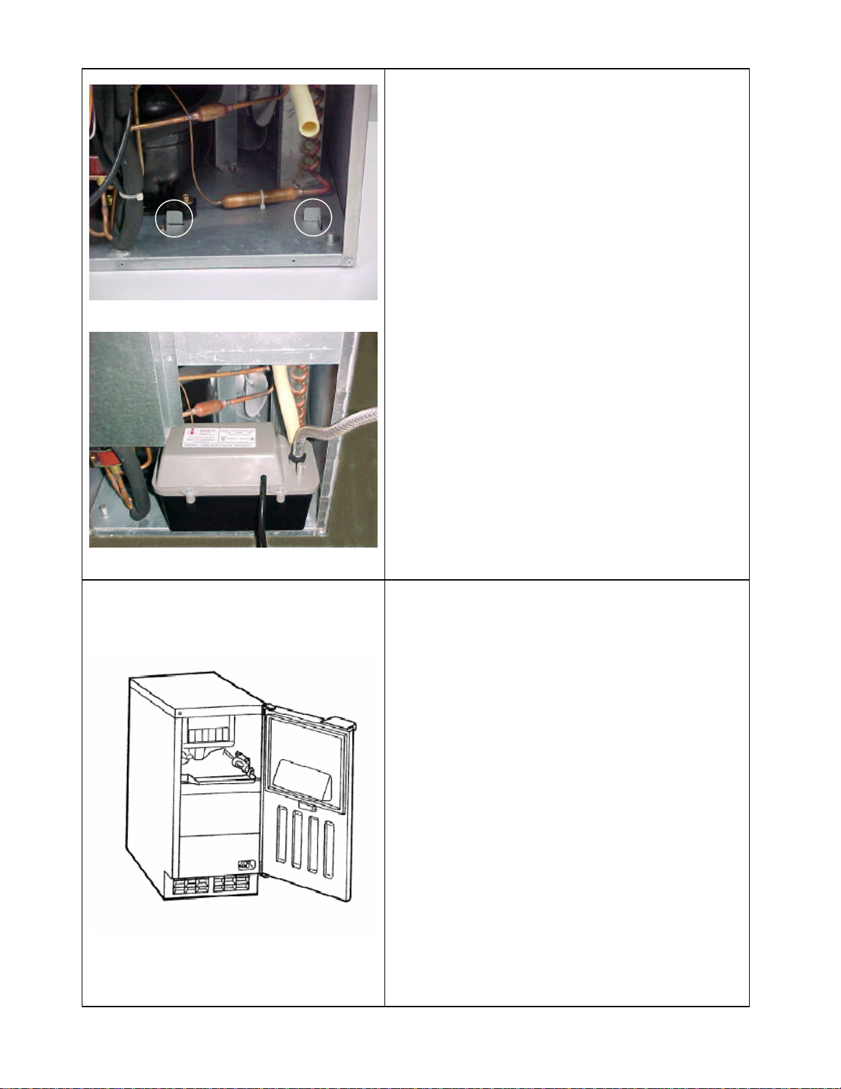
In the case of an AM-50 if a drain is not
located in an area that will allow for the
proper fall, there is an optional condensate
pump available that can be installed directly
into the unit. After removing the louvered
rear panel the pump location is defined by
the two metal tabs. This pump has a built in
safety that will shut the AM-50 down in the
event of a pump problem. This pump is
available as an accessory through your local
distributor. Simply follow the instructions
included with the pump for details on the
installation.
The AM-50 door can be field converted from
the standard right hinged door to a left
hinged door without the use of any additional
hinge kits. The AM-100 and AM-150 use a
spring loaded drop down door design
therefore can not be reversed.
This procedure for reversing the AM-50 door
is shown in the Instruction Manual provided
with the unit. View this manual at
www.hoshizaki.com.
- 4 -
(AM
-
50)
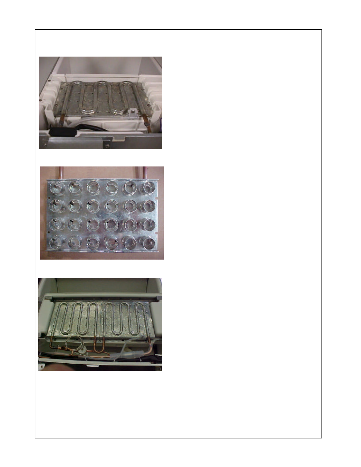
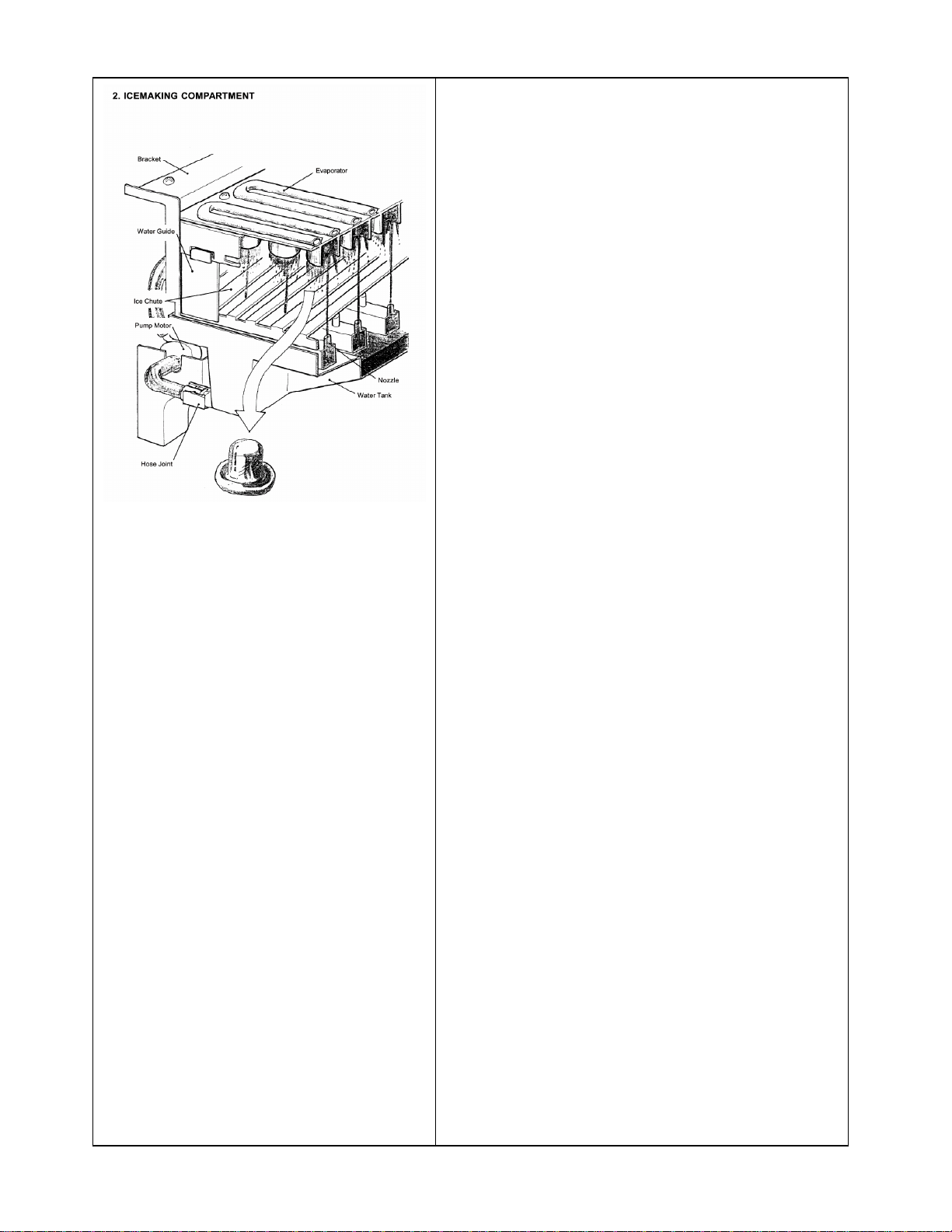
The horizontal evaporator and water
distribution system are unique to the
Hoshizaki AM and IM series. The AM and
the IM series are similar in the fact that they
both make ice on a horizontal evaporator.
The AM evaporator design however is
different, as shown in the center picture. The
moving IM water plate and associated parts
are eliminated with this simple design.
The AM-50BAE produces 24 cubes and .60
pounds per cycle. The AM-100BAE and
AM-150BAF produce 60 cubes and 1.54
pounds per cycle.
The AM series sequence of operation is also
different. The sequence of operation for the
AM series will be explained in the following
pages.
(AM-100 & AM-150)
- 5 -
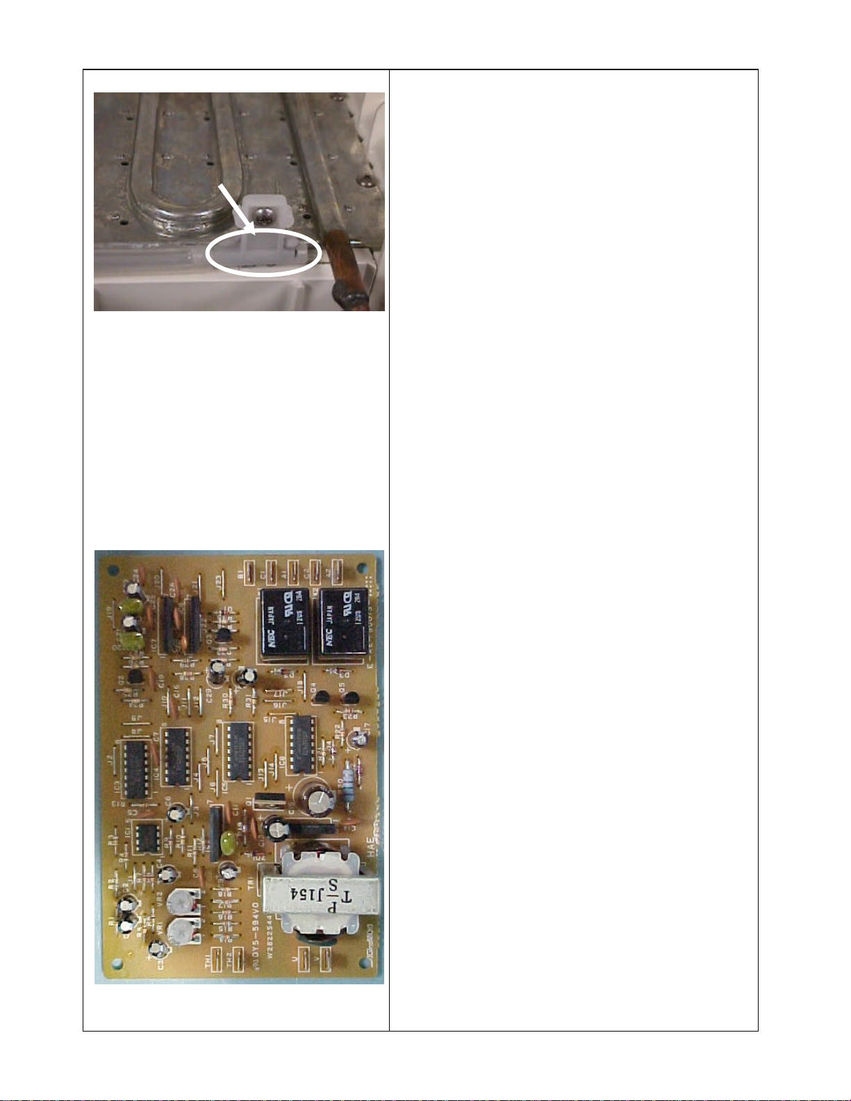
THERMISTOR
The AM series uses a combination
thermistor and control board to control the
sequence of operation. When the toggle
switch is placed in the “ON” position and
the bin control calls for ice, the unit will
begin in the initial harvest cycle. Starting
Thermistor
the unit in harvest allows the compressor to
start in an unloaded condition, greatly
extending the life of the compressor. This
operation is common among all Hoshizaki
cube icemakers.
During the initial harvest, the compressor,
hot gas valve and water valve will be
energized. The initial harvest is a timed
harvest. After 50 seconds, the control board
will energize the X1 board relay to start the
pump motor and condenser fan motor,
switching the unit into the freeze cycle.
After the initial harvest, the X2 board relay
will remain energized during the freeze
cycle. This allows the water valve to feed
fresh water for an additional 50 seconds.
This extended fill, only takes place when the
unit has restarted from a power interruption
or when the bin control calls for ice. During
the normal harvest cycle the water valve
will de-energize at the beginning of freeze
or in the event of long harvest the valve will
have a maximum open time of 102 seconds.
This could occur in the event of operation in
low water and ambient temperatures. During
normal operating conditions the unit will
run approximately 2~4 minutes in the
harvest cycle.
- 6 -
Note:
*A thermistor temperature of
minute
A thermistor temperature of
will start the 50
26.6°F (-3°C) will start 8
freeze completion timer.
*
44.6°F (7°C)
second defrost completion timer.
* 26.6°F (-3°C) = 6.8KΩ
thermistor resistance.
* 44.6°F (+7°C) = 4.5KΩ
thermistor resistance.
Throughout the freeze cycle, which
normally last 14~33 minutes, depending on
model and operating conditions, the unit
will continue to circulate the water from the
reservoir to the horizontal evaporator,
through the spray tubes. When the
temperature of the evaporator has reached
approximately 26.6°F (-3°C) and the
thermistor signals approximately 6. 8KΩ the
freeze completion timer will start and count
down 8 minutes.
The control board will then switch to normal
harvest, re-energize the X2 relay and deenergize the X1 relay. This opens the hot
gas valve and water valve and de-energizes
the condenser fan motor and water pump. A
normal harvest is temperature and time
terminated and uses the same thermistor
used to terminate the freeze cycle. After the
evaporator warms to approximately 44.6°F
(+7°C) the thermistor signals the control
board with a resistance of approximately
4.5KΩ. The control board then starts the
harvest completion timer, which is set at 50
seconds. When this timer completes 50
seconds, it ends the harvest cycle and begins
freeze.
The unit will continue to cycle between
freeze and harvest until the bin control
opens, signaling a full bin or until power is
interrupted
- 7 -
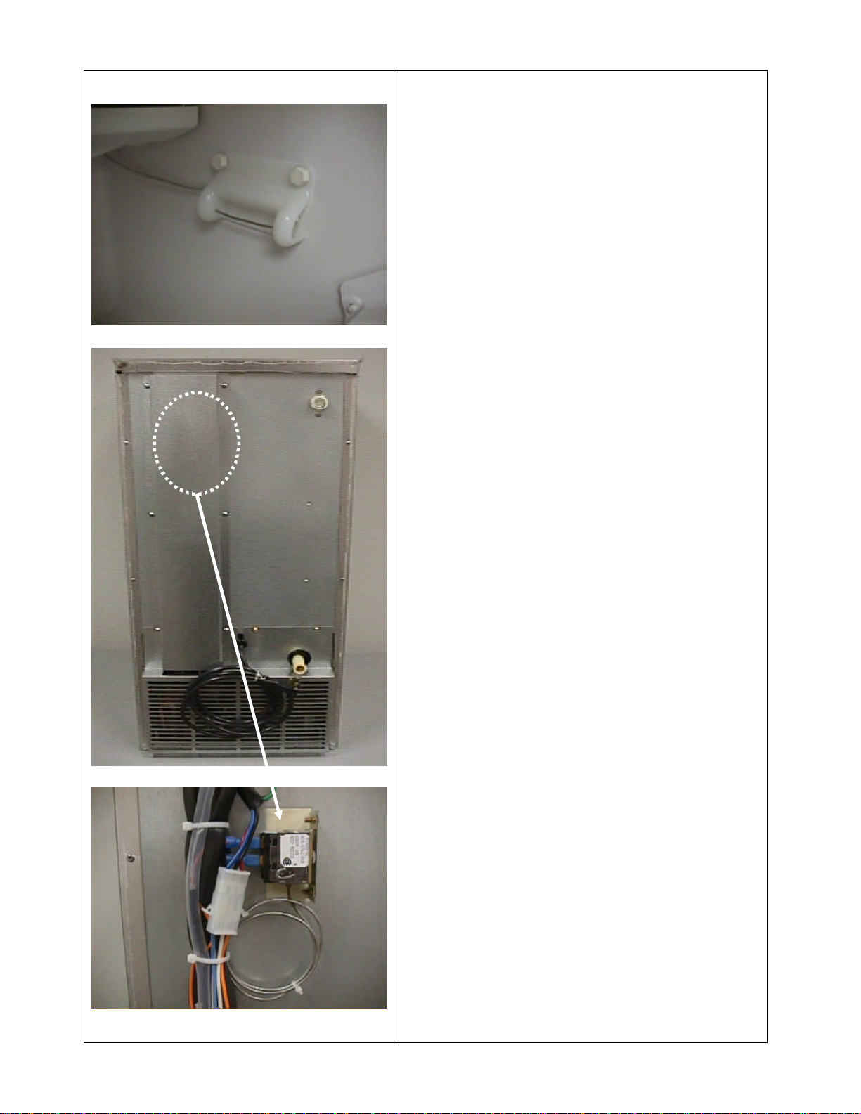
seconds after ice contacts the bulb.
The AM series uses a thermostatic bin
control located on the right rear side of the
ice storage compartment. This control will
open when ice touches the sensing bulb and
the unit will shut down
This control includes a small heater to
eliminate the control opening due to low
ambient temperatures in the bin.
Access the control by removing the wiring
channel from the rear of the unit.
The thermostatic bin control is factory set
and should shut down the unit within 10
Adjustment may be necessary in higher
altitudes.
- 8 -
the louvered panel must be removed.
(AM-50BAE)
AM-50BAE: The control switch is marked
“ICE- OFF-WASH” and is located on the
lower right front of the unit .
AM-100 & AM-150: The control switch is
located on the control box which is located
behind the front panel on the left hand side
of the unit .
If it is necessary to gain access to the control
box,
AM-50BAE: This can be done by removing
the two screws from the lower portion of the
front panel and pulling the panel down
slightly to dis-engage the mounting tabs.
AM-100 & AM-150: Remove the middle
screw at the bottom of the front panel and lift
off.
(AM-100 & AM-150)
(AM-50BAE)
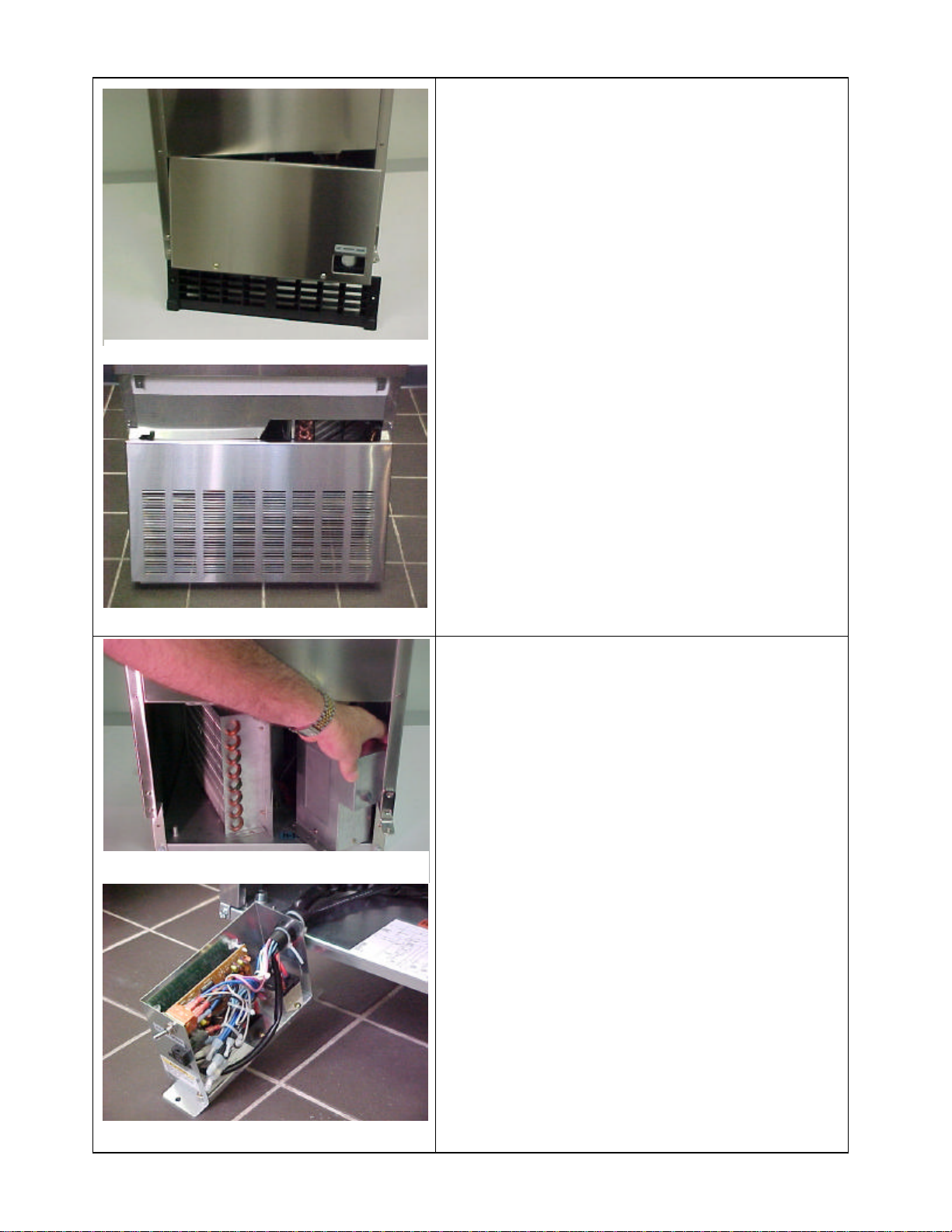
The control box is held in place with 2 hex
head bolts. Once the bolts are removed,
AM-50BAE: The control box can be rotated
approximately 45° CCW allowing easier
access to the control box cover and control
board.
AM-100 & AM-150: The control box can be
pulled out to the front of the unit after the
two bolts have been removed.
(AM-100 & AM-150)
- 9 -
CONTROL BOARD:
A solid state board controls the AM
operation. The control board is factory
adjusted to produce consistent ice in all
ambient conditions.
“NO SEASONAL
ADJUSTMENTS ARE
REQUIRED”
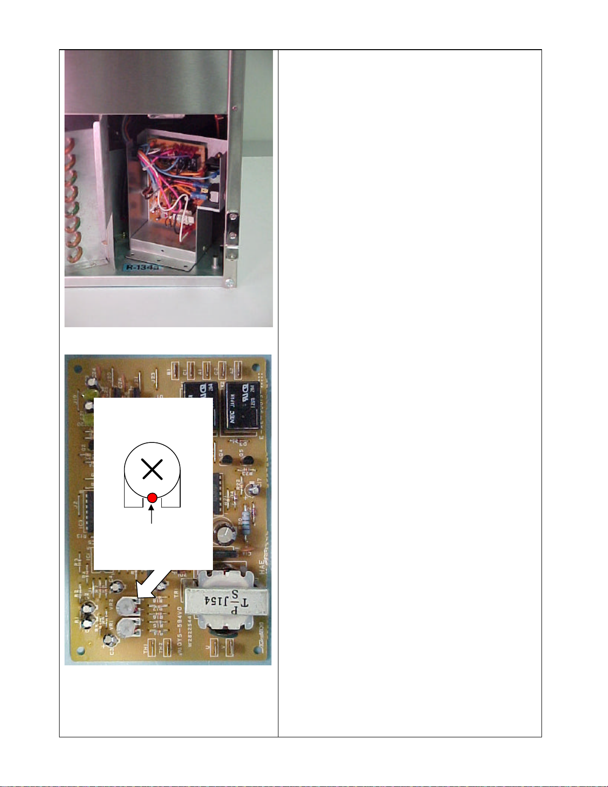
There are no adjustments needed, however
VR1 & VR2
are factory adjusted.
Red paint seals the
setting for VR1 &
VR2 at this point.
there are two variable resistors on the control
board. The first resistor VR1 is used to fine
tune the harvest termination temperature
adjustment when the control board is
manufactured. The adjustment is sealed with
red paint and should always remain in the
factory setting.
VR2 is set from the factory so that the ice
machine will perform at the optimum level.
This resistor adjusts the freeze cycle
termination setting so the proper cube size is
obtained. The VR2 setting is also sealed with
red paint and should not be changed.
If you find that the red seal is broken, the
board will need to be replaced since these
settings cannot be correctly adjusted in the
field. The replacement board will be factory
set and sealed for proper operation.
- 10 -

Preventative maintenance for the AM is
simple. Follow these steps to allow the unit
to operate efficiently.
1. Clean the condenser once a year using a
brush or vacuum.
2. Check and clean the inlet water valve
screen as needed to assure proper water
flow.
*Remember that the original fitting is a 3/4” BSP
and the use of a standard MPT fitting will
damage the threads. In May of 2003, this fitting
was changed to 3/8” male flare. After August
and September of 2003, this fitting was changed
to a 1/2" FPT.
3. Clean and sanitize the water distribution
system annually using the recommended
cleaner. (See the next page for detailed
information on cleaning the water
system)
4. Wipe down the exterior using a soft cloth
and neutral cleaner.
The AM ser ies uses a magnetic pump. This
style of pump allows the water portion of the
pump to be completely sealed from the
motor. This eliminates the need for a
mechanical seal and eliminates the
possibility of water entering the pump
through the pump end.
If the pump does not pump and is being
energized then remove the four screws from
the front of the pump and check for any
debris that may be binding the impeller
- 11 -

Cleaning tips:
• A detailed cleaning label is located on the
back of the icemaker door of the AM50BAE or on the back of the bin baffle of
the AM-100 & AM-150. More detailed
instructions are included in the customers
Instruction Manual or in the product
Service Manual. This manuals can be
viewed at www.hoshizaki.com
• Always follow the cleaning instructions
and use the recommended ice machine
cleaner.
The following instructions provide
information on the disassembly of the water
Water circuit disassembly
circuit. Before starting these steps it will be
necessary to remove the hinged slope from
the pins at the front edge of the bin.
Remove each Separator by lifting it to the
horizontal position and pushing it hard
inward. Remove all the separators the same
way, clean and sanitize them
- 12 -

(AM
-
50)
(AM
-
100 & AM
-
150
)
(AM
-
50BAE)
Disconnect the suction tube that connects
the pump motor to the sump tank.
The AM -50BAE has a locking tabs that can
be released by compressing both plastic tabs
to unlock the joint in the direction of the
black arrows and pulling the pipe clear to
drain the Tank.
AM-100BAE & AM-150BAF simply pull
the pipe of the connector
AM-50: Spread out the tabs on both sides to
unlock the water tank, and pull it out toward
you. Clean and sanitize the water tank.
AM-100 & AM-150: Remove the
thumbscrews on both sides of the water tank
and pull it out toward you. Clean and
(AM-100 & AM-150)
sanitize the water tank
- 13 -

(AM
-
50)
AM-50BAE: Lift off the ice chute from the
front frame pipe and then from the rear
frame pipe clean and sanitize the ice chute
The AM-100 & AM-150: ice chute is
incorporated into the wat er plate and will be
removed as one assembly in the next step.
Check to see if cube guide pulls out with
sump tank
Pull the discharge tube from the spray
assembly. Remove the assembly by pulling
it toward you.
(AM-100 & AM-150)
(AM-50)
Remove the caps to clean and sanitize the
spray assembly. If the nozzles are clogged,
clean them with a small wire or suitable
brush.
(AM-100 & AM-150)
- 14 -

(AM
-
50)
(AM
-
50)
Refit the caps on the cleaning outlets to seal
them off.
(AM-100 & AM-150)
AM-50: Slide in the spray assembly along
the rails on the right and left brackets. Refit
the discharge tube securely on the spray
outlet. Note: A loose fitting may cause a
water leak and improper water spray during
freeze.
AM-100 & AM-150: Slide the water plate
(AM-100 & AM-150)
along the mechanism base. Refit the
discharge tube securely on the spray outlet.
A loose fitting may cause a water leak.
- 15 -

(AM
-
50)
AM-50: Position and lock the ice chute on to
the front and rear frame pipes by pushing the
chute down until it clicks
AM-100 & AM-150: Place the rear of the
water tank on the water tank rest at the back
of the storage bin. Use the thumbscrews to
secure the front of the water tank to the
mechanism base.
(AM-100 &AM-150)
AM-50: Slide in the water tank along the
rails at the bottom of the right and left
brackets until it clicks into place
- 16 -

(AM-50)
AM-50BAE: Refit the suction tube on to the
water tank inlet by pushing the joint to lock
it securely in the arrow directions.
The AM-100 & AM-150 uses a simple push
on suction hose.
Note: A loose fitting may cause a water
(AM-100 & AM-150)
leak.
Hook each separator on the rail and pull it
hard toward you until it locks in place with a
click. Refit all the separators in the same
way.
Refit the bin slope in its correct position
- 17 -

AM
-
50BAE
- 18 -

- 19 -

- 20 -

Electrical Specifications:
AM-50BAE
The unit is 115 volt/ 60 hz. /1ph.
The AM-Series should be connected to a separate 15Amp circuit.
- 21 -

Electrical Specifications:
AM-100BAE
The unit is 115 volt/ 60 hz. /1ph.
The AM-Series should be connected to a separate 15Amp circuit.
- 22 -

Electrical Specifications:
AM-150BAF
The unit is 115 volt/ 60 hz./1ph.
The AM-Series should be connected to a separate 15Amp circuit.
- 23 -

High side process tube
Thermistor
AM-50BAE R
-
134a 4.2 oz
AM-50BAE & AM-100BAE
AM-100BAE R-134a 6.6 oz
Low side process tube
Note: All Hoshizaki ice machines are critically charged. Since the AM- series have small refrigeration circuits and the AM100 and AM-150 use cap tube systems this is especially true. The AM- series does not come from the factory with any type
of refrigeration system access. In the event that the system must be accessed for troubleshooting it will be necessary to
install piercing type “saddle valve” on the system. These valves should only be installed on the process tubes provided on
the low side and high side of the system. After the repair has been made to the unit, sweat type schraders should be installed
in place of the piercing valves.
Again, these units are critical charged. Every precaution should be taken to insure that the exact charge of R134a for the
AM-50 and AM-100 and R-404a for the AM-150 is weighed into the system. Due to the very small charge of these units ,
extra care must be taken to avoid any refrigerant loss when removing gauges.
- 24 -

AM
-
150BAF
system. These valves should only be installed on the process tubes provided on the low side and high side of the system.
High side process tube
WATER AND REFRIGERATION CIRCUIT
AM-150BAF 9.5oz R-404a
Low side process tube
Note: All Hoshizaki ice machines are critically charged. Since the AM-series have small refrigeration circuits this is
especially true. The AM-series does not come from the factory with any type of refrigeration system access. In the event
that the system must be accessed for troubleshooting it will be necessary to install piercing type “saddle valve” on the
After the repair has been made to the unit, sweat type schraders should be installed in place of the piercing valves.
Again, these units are critical charged. Every precaution should be taken to insure that the exact charge of R134a for the
AM-50 and AM-100 and R-404a for the AM-150 is weighed into the system. Due to the very small charge of these units,
extra care must be taken to avoid any refrigerant loss when removing gauges.
- 25 -

Freeze time
= T
hermistor reads 26.6º
F (-3ºC) then completes 8 minute Freeze cycle comple
tion timer
.
Harvest time = Thermistor reads 44.6ºF (+7ºF) then completes 50 second defrost completion timer.
- 26 -

SERVICE DIAGNOSIS
- 27 -

- 28 -

- 29 -

AM SERIES REVIEW QUIZ
Choose the best answer for each question below.
1. The AM control board is located in the rear or the unit.
True False
2. The AM unit uses a thermostatic bin control.
True False
3. The bin control switch must OPEN or CLOSE to shut the unit down?
4. The AM-150BAF series uses R-404a or R-134a refrigerant.
5. The AM Series only uses one thermistor located on the evaporator?
True False
6. The freeze cycle is temperature and time terminated.
True False
7. On the initial freeze cycle the water valve will remain open for 50 seconds.
True False
8. The water valve will remain energized for the entire harvest cycle regardless of
how long.
True False
9. The AM-50BAE makes a square cube.
True False
NOTE: Quiz answers are at the bottom of next page.
- 30 -

(NOTES)
Quiz answers:
1.False, 2. True, 3. Open, 4. R-404a, 5. True, 6. True, 7. True, 8. False., 9. False
- 31 -
 Loading...