


 Loading...
HoshizakiHoshizaki America, Inc.
Commercial Refrigerators & Freezers
Models
SafeTemp®
“A Superior Degree
of Reliability”
www.hoshizaki.com
SERVICE MANUAL
Number: 73096
Issued: 10-9-2000
Revised: 3-7-2007
IMPORTANT
Only qualified service technicians should attempt to service or maintain this unit. No such service or maintenance should be undertaken until the technician has thoroughly read this Service Manual.
HOSHIZAKI provides this manual primarily to assist qualified service technicians in the service and maintenance of the unit.
Should the reader have any questions or concerns which have not been satisfactorily addressed, please call, write or send an e-mail message to the HOSHIZAKI Technical Support Department for assistance.
HOSHIZAKI AMERICA, INC.
618 Highway 74 South
Peachtree City, GA 30269
Attn: HOSHIZAKI Technical Support Department
Phone: 1-800-233-1940 Technical Service (770) 487-2331
Fax: 1-800-843-1056 (770) 487-3360
E-mail: techsupport@hoshizaki.com
Web Site: www.hoshizaki.com
NOTE: To expedite assistance, all correspondence/communication MUST include the following information:
•Model Number
•Serial Number
•Complete and detailed explanation of the problem
Please review this manual. It should be read carefully before the unit is serviced or maintenance operations are performed. Only qualified service technicians should service and maintain the unit. This manual should be made available to the technician prior to service or maintenance.
CONTENTS |
|
I. Specifications...................................................................................................................... |
5 |
A. Nameplate Ratings........................................................................................................ |
5 |
B. Dimensions.................................................................................................................... |
5 |
1. Notes for All Units..................................................................................................... |
5 |
2. RH1-AAC(-HD), FH1-AAC(-HD)............................................................................... |
6 |
3. RH2-AAC(-HD), FH2-AAC(-HD)............................................................................... |
7 |
4. RH3-AAC(-HD)......................................................................................................... |
8 |
II. General Information............................................................................................................ |
9 |
A. Sequence of Operation and Timing Charts................................................................... |
9 |
1. Refrigerator ............................................................................................................. |
9 |
2. Freezer................................................................................................................... |
11 |
B. Control Module............................................................................................................ |
13 |
1. Settings and Adjustments....................................................................................... |
13 |
2. Service Menu......................................................................................................... |
14 |
C. Thermistors.................................................................................................................. |
16 |
1. Cabinet Thermistor (SEN1: white and black leads)................................................ |
16 |
2. Defrost Thermistor (SEN2: black and red leads) ................................................... |
16 |
3. Thermistor Check Procedure................................................................................. |
16 |
D. Compressor Protector.................................................................................................. |
17 |
E. Safety Devices............................................................................................................. |
17 |
1. Pressure Switch..................................................................................................... |
17 |
2. Defrost Protection.................................................................................................. |
17 |
F. Perimeter Frame Heater............................................................................................... |
17 |
III. Service Diagnosis........................................................................................................... |
18 |
A. Diagnosis Chart........................................................................................................... |
18 |
IV. Removal and Replacement of Components.................................................................... |
21 |
A. Service for Refrigerant Lines....................................................................................... |
21 |
1. Refrigerant Recovery............................................................................................. |
21 |
2. Brazing................................................................................................................... |
21 |
3. Evacuation and Recharge [R-134a, R-404A]......................................................... |
22 |
B. Removal and Replacement of Compressor................................................................. |
23 |
C. Removal and Replacement of Expansion Valve.......................................................... |
24 |
D. Removal and Replacement of Evaporator................................................................... |
25 |
E. Removal and Replacement of Door Gasket................................................................ |
25 |
F. Removal and Replacement of Door Closure Spring..................................................... |
26 |
G. Door Re-Hinging.......................................................................................................... |
27 |
H. Removal and Replacement of Control Module............................................................ |
28 |
I. Removal and Replacement of Thermistors................................................................... |
29 |
V. Cleaning Instructions........................................................................................................ |
32 |
VI. Wiring Diagrams.............................................................................................................. |
33 |
A. RH1-AAC(-HD)............................................................................................................ |
33 |
B. RH2-AAC(-HD)............................................................................................................ |
34 |
C. RH3-AAC(-HD)............................................................................................................ |
35 |
D1. FH1-AAC(-HD) (auxiliary code P-7 and earlier)........................................................ |
36 |
D2. FH1-AAC(-HD) (auxiliary code P-8 and later)........................................................... |
37 |
E1. FH2-AAC(-HD) (auxiliary code P-5 and earlier)......................................................... |
38 |
E2. FH2-AAC(-HD) (auxiliary code P-6 and later)............................................................ |
39 |

I. Specifications
A. Nameplate Ratings
|
|
|
Design Pressure |
Refrigerant and |
|||
|
|
|
|
(PSIG) |
Refrigerant Charge |
||
|
AC Supply Voltage |
Amperes |
HI |
|
LO |
R-404A |
R-134a |
RH1-AAC / RH1-AAC-HD |
115/60/1 |
5.0 |
240 |
|
120 |
|
9.3 OZ |
FH1-AAC / FH1-AAC-HD |
115/60/1 |
12 |
475 |
|
250 |
15.2 OZ |
|
RH2-AAC / RH2-AAC-HD |
115/60/1 |
7.0 |
240 |
|
120 |
|
11.6 OZ |
FH2-AAC / FH2-AAC-HD |
115/60/1 |
15.5 |
450 |
|
250 |
20.1 OZ |
|
RH3-AAC / RH3-AAC-HD |
115/60/1 |
12.0 |
250 |
|
120 |
|
20.6 OZ |
RH1-AAC-W |
115/60/1 |
7.0 |
450 |
|
200 |
12.2 OZ |
|
B. Dimensions
1.Notes for All Units
1)Units shipped with 4" casters
2)Optional legs have 25.4 mm (1 in.) height adjustment
|
Door Opening |
Total |
Total Shelf |
|
|
|
|
Refrigerated |
Space ft2 |
|
Width |
Height |
||
|
Volume ft3 |
|
||
|
mm (in.) |
mm (in.) |
|
|
|
|
|
||
RH1-AAC / FH1-AAC |
554.8 (21.8) |
1507 (59.3) |
22.3 |
11.5 |
RH1-AAC-HD / FH1-AAC-HD |
554.8 (21.8) |
681.7 (26.8) |
22.3 |
|
RH2-AAC / FH2-AAC |
554.8 (21.8) |
1507 (59.3) |
48.3 |
25.9 |
RH2-AAC-HD / FH2-AAC-HD |
554.8 (21.8) |
681.7 (26.8) |
48.3 |
|
RH3-AAC |
554.8 (21.8) |
1507 (59.3) |
73.7 |
40.3 |
RH3-AAC-HD |
554.8 (21.8) |
681.7 (26.8) |
73.7 |
|
See the nameplate for electrical and refrigeration specifications. The nameplate is located on the right side wall of the cabinet interior.
Note: We reserve the right to make changes in specifications and design without prior notice.
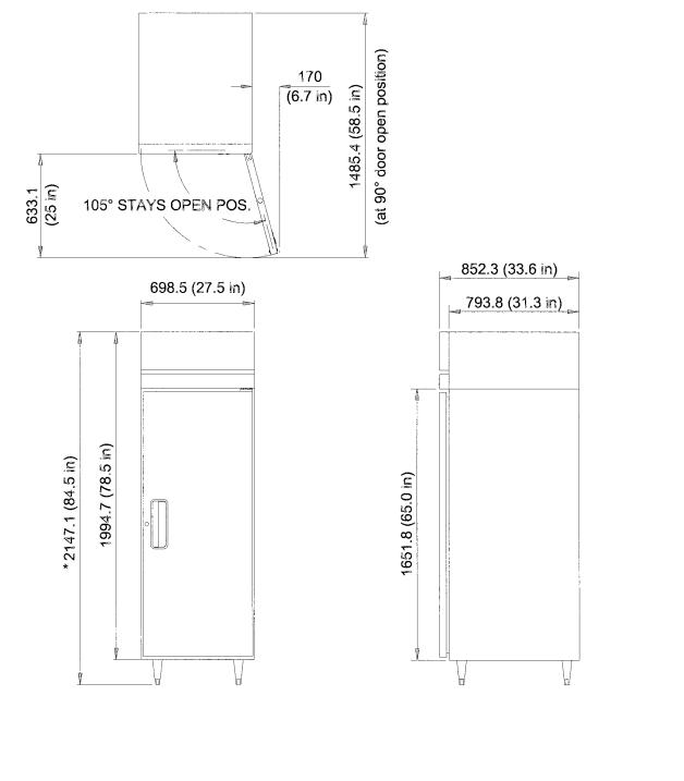
2. RH1-AAC(-HD), FH1-AAC(-HD)
mm (in.)
* Shown with optional 6" legs; 4" casters are standard
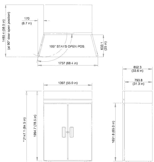
3. RH2-AAC(-HD), FH2-AAC(-HD)
mm (in.)
* Shown with optional 6" legs; 4" casters are standard

4. RH3-AAC(-HD)
mm (in.)
* Shown with optional 6" legs; 4" casters are standard
II. General Information
A. Sequence of Operation and Timing Charts
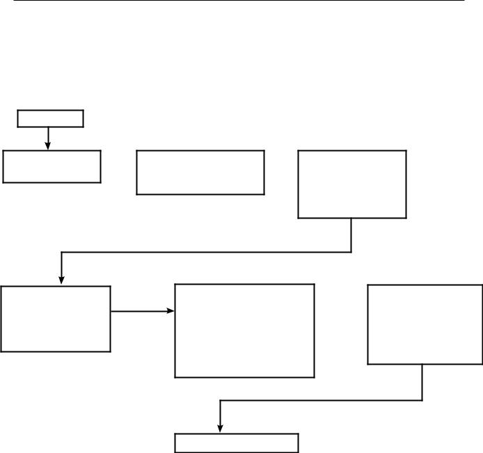
1. Refrigerator
a) Sequence of Operation
POWER ON
1. Frame heaters on  2.0 minute delay
2. Evaporator fan on 1. Compressor start-up
2. Condenser fan start-up
 Cycle Off (Cut-out temperature reached) [Minimum 2.0 minutes]
1.Compressor off
2.Condenser fan off
Cycle On (Cut-on temperature reached) [Minimum 2.0 minutes]
1.Compressor on
2.Condenser fan on
If evaporator temperature reaches 13°F, unit initiates defrost. Defrost initiation for RH1-AAC-W is 7°F.
1.Compressor off
2.Condenser fan off
(Note: Evaporator fan is on.)
 Evaporator temperature reaches 40°F, defrost terminated
1.Compressor on
2.Condenser fan on
Normal cycling continues
Note: The start circuit of the compressor is timed such that at power-up and during any compressor off time, there will be at least a 2 minute delay before the compressor will start. The compressor has a 2 minute minimum run time during every run cycle. The only exception is when the overload activates and deactivates.

b)Timing Chart
For Refrigerator
10
2. Freezer
a) Sequence of Operation
POWER ON
Initiate Defrost
1.Compressor off
2.Evaporator fan off
3.Condenser fan off
4.Defrost heater on
5."dEF" displayed
6.Frame heaters on
Cycle On (Cut-on temperature reached) [Minimum 2.0 minutes]
1.Compressor on
2.Condenser fan on
|
|
|
|
|
|
|
|
|
|
Five minutes after |
|
||
|
|
|
|
|
|
|
|
|
|
defrost heater off |
|
||
|
|
|
|
Defrost End |
|
|
|
1. Compressor on |
|
||||
|
|
|
|
|
|
|
|
||||||
|
|
|
|
Defrost thermistor |
|
|
|
2. Condenser fan on |
|
||||
|
|
|
|
reaches 100°F; |
|
|
|
3. "rEC" displayed |
|
||||
|
|
|
|
Defrost heater off |
|
|
|
|
|
|
|
||
|
|
|
|
|
|
|
|
|
|
|
|
|
|
|
|
|
|
|
|
|
|
|
|
|
|
||
|
|
|
|
|
|
|
|
|
|
|
|
|
|
|
|
|
|
|
|
|
|
|
Evaporator temperature |
||||
|
|
|
|
|
|
|
|
|
drops to 70°F |
||||
|
|
|
|
|
|
|
|
|
|||||
|
|
|
|
|
|
|
|
|
1. Evaporator fan on |
||||
|
|
|
|
|
|
|
|
|
|
|
|
|
|
|
|
|
|
|
|
|
|
|
|
|
|
||
|
|
|
|
|
|
|
|
|
|
|
|
|
|
|
|
Cycle Off (Cut-out |
|
|
|
|
Cabinet thermistor drops |
||||||
|
|
|
|
|
|
||||||||
|
|
temperature reached) |
|
|
|
|
|||||||
|
|
|
|
|
|
to 15°F above setpoint. |
|||||||
|
|
[Minimum 2.0 minutes] |
|
|
|
|
|||||||
|
|
|
|
|
|
1. "rEC" no longer |
|||||||
|
|
1. Compressor off |
|
|
|
|
|||||||
|
|
|
|
|
|
displayed; cabinet temp. |
|||||||
|
|
2. Condenser fan off |
|
|
|
|
|||||||
|
|
|
|
|
|
displayed |
|||||||
|
|
|
|
|
|
|
|
|
|||||
|
|
|
|
|
|
|
|
|
|
|
|
|
|
|
Defrost Start |
|
|
|
Defrost End |
|
||
|
|
|
|
|
||||
|
|
|
|
|
||||
|
Preprogrammed time interval |
|
|
Defrost thermistor |
|
|||
|
1. Compressor off |
|
|
|
reaches 100°F; |
|
||
|
2. Evaporator fan off |
|
|
|
Defrost heater off |
|
||
|
3. Condenser fan off |
|
|
|
|
|
||
|
|
|
|
|
||||
|
4. Defrost heater on |
|
|
|
|
|
||
|
5. "dEF" displayed |
|
|
|
|
|
||
|
|
|
|
|
|
|
|
|
|
|
|
|
|
|
|
||
|
|
|
|
Cabinet thermistor drops to |
|
|||
|
|
|
|
15°F above setpoint. |
|
|||
|
|
|
|
1. "rEC" no longer displayed; |
|
|||
Normal cycling continues |
|
|
cabinet temp. displayed |
|
||||
|
|
|
|
|
|
|
|
|
Five minutes after defrost heater off
1.Compressor on
2.Condenser fan on
3."rEC" displayed
Evaporator temperature drops to 70°F
1. Evaporator fan on
Note: For freezers, defrost will be initiated at power-up. To bypass initial defrost, press and hold the up arrow button on the control module while turning on the toggle switch. The display should read a temperature. There will be at least a 2 minute delay before the compressor will start even if the initial defrost cycle is bypassed. The compressor has a 2 minute minimum run time during every run cycle. The only exception is when the overload activates and deactivates.
11

b) Timing Chart
For Freezer
12
Loading...