


Hoshizaki IM-240DNE, IM-240DWNE, IM-240DWNEC, IM-240DSNE, IM-240XNE SERVICE MANUAL
...NO. E1CK-810
ISSUED: JUN. 28, 2010
REVISED: JUN. 27, 2014
HOSHIZAKI
MODULAR CUBER
MODEL IM-240DNE/DWNE(-C)
IM-240DSNE IM-240XNE/XWNE(-C) IM-240XSNE IM-240ANE/AWNE
SERVICE MANUAL
CONTENTS |
PAGE |
I. SPECIFICATIONS-------------------------------------------------------------------------------------- |
1 |
1. DIMENSIONS/SPECIFICATIONS-------------------------------------------------------------- |
1 |
[a] IM-240DNE [Copeland compressor: auxiliary code B0 and earlier]---------------- |
1 |
[b] IM-240DNE [Danfoss compressor: auxiliary code B1 and later]-------------------- |
2 |
[c] IM-240DNE-C------------------------------------------------------------------------------------ |
3 |
[d] IM-240DWNE [Copeland compressor: auxiliary code B0 and earlier]------------- |
4 |
[e] IM-240DWNE [Danfoss compressor: auxiliary code B1 and later]----------------- |
5 |
[f] IM-240DWNE-C---------------------------------------------------------------------------------- |
6 |
[g] IM-240ANE [Copeland compressor: auxiliary code B0 and earlier]---------------- |
7 |
[h] IM-240ANE [Danfoss compressor: auxiliary code B1 and later]-------------------- |
8 |
[i] IM-240AWNE [Copeland compressor: auxiliary code B0 and earlier]-------------- |
9 |
[j] IM-240AWNE [Danfoss compressor: auxiliary code B1 and later]---------------- |
10 |
[k] IM-240DSNE [Danfoss Compressor]---------------------------------------------------- |
11 |
[l] URC-240C-E-4 (Condenser Unit)---------------------------------------------------------- |
12 |
II. GENERAL INFORMATION------------------------------------------------------------------------ |
13 |
1. CONSTRUCTION--------------------------------------------------------------------------------- |
13 |
[a] IM-240DNE/XNE, IM-240DNE-C/XNE-C----------------------------------------------- |
13 |
[b] IM-240DWNE/XWNE, IM-240DWNE-C/XWNE-C------------------------------------ |
14 |
[c] IM-240ANE------------------------------------------------------------------------------------- |
15 |
[d] IM-240AWNE---------------------------------------------------------------------------------- |
16 |
[e] IM-240DSNE----------------------------------------------------------------------------------- |
17 |
[f] URC-240C-E-4--------------------------------------------------------------------------------- |
18 |
2. CONTROLLER BOARD------------------------------------------------------------------------- |
19 |
[a] CONTROLLER BOARD LAYOUT-------------------------------------------------------- |
20 |
[b] INPUT/OUTPUT LAYOUT------------------------------------------------------------------ |
21 |
[c] BEFORE CHECKING CONTROLLER BOARD--------------------------------------- |
22 |
III. OPERATING INSTRUCTIONS------------------------------------------------------------------ |
23 |
1. START UP------------------------------------------------------------------------------------------- |
23 |
2. PREPARING THE ICEMAKER FOR LONG STORAGE-------------------------------- |
24 |
3. BIN CONTROL------------------------------------------------------------------------------------- |
25 |
[a] BIN CONTROL SWITCH ASSEMBLY--------------------------------------------------- |
25 |
[b] REMOVAL-------------------------------------------------------------------------------------- |
26 |
IV. MAINTENANCE INSTRUCTIONS-------------------------------------------------------------- |
27 |
1. PERIODICAL CLEANING----------------------------------------------------------------------- |
27 |
2. WATER VALVE------------------------------------------------------------------------------------ |
29 |
3. WATER-COOLED CONDENSER------------------------------------------------------------- |
30 |
4. ICEMAKING WATER SYSTEM---------------------------------------------------------------- |
31 |
V. TECHNICAL INFORMATION--------------------------------------------------------------------- |
34 |
1. WATER CIRCUIT AND REFRIGERANT CIRCUIT--------------------------------------- |
34 |
[a] IM-240DNE/XNE, IM-240DNE-C/XNE-C, IM-240ANE------------------------------ |
34 |
[b] IM-240DWNE/XWNE, IM-240DWNE-C/XWNE-C, IM-240AWNE---------------- |
35 |
i
[c] IM-240DSNE/XSNE+URC-240C-E-4---------------------------------------------------- |
36 |
2. WIRING DIAGRAM------------------------------------------------------------------------------- |
37 |
[a] IM-240DNE(-C)/XNE(-C), IM-240DWNE(-C)/XWNE(-C), |
|
IM-240ANE/AWNE--------------------------------------------------------------------------- |
37 |
[b] IM-240DSNE/XSNE+URC-240C-E-4---------------------------------------------------- |
38 |
3. PERFORMANCE DATA------------------------------------------------------------------------- |
39 |
[a] COPELAND COMPRESSOR-------------------------------------------------------------- |
39 |
[b] SECOP (DANFOSS) COMPRESSOR-------------------------------------------------- |
42 |
VI. SERVICE DIAGNOSIS---------------------------------------------------------------------------- |
46 |
1. ERROR CODE INDICATION------------------------------------------------------------------- |
46 |
2. NO ERROR CODE INDICATION------------------------------------------------------------- |
47 |
VII. ADJUSTMENT-------------------------------------------------------------------------------------- |
49 |
1. EXPANSION VALVE------------------------------------------------------------------------------ |
49 |
2. WATER REGULATING VALVE - WATER-COOLED MODEL ONLY----------------- |
50 |
3. FULL DRAIN FLUSH----------------------------------------------------------------------------- |
50 |
4. DIMPLE DIAMETER------------------------------------------------------------------------------ |
50 |
VIII. REMOVAL AND REPLACEMENT------------------------------------------------------------ |
52 |
1. SERVICE FOR REFRIGERANT LINES----------------------------------------------------- |
52 |
[a] SERVICE INFORMATION------------------------------------------------------------------ |
52 |
[b] REFRIGERANT RECOVERY-------------------------------------------------------------- |
53 |
[c] EVACUATION AND RECHARGE--------------------------------------------------------- |
53 |
2. COMPRESSOR----------------------------------------------------------------------------------- |
54 |
3. DRIER------------------------------------------------------------------------------------------------ |
55 |
4. EXPANSION VALVE------------------------------------------------------------------------------ |
56 |
5. EVAPORATOR------------------------------------------------------------------------------------- |
57 |
6. HOT GAS VALVE---------------------------------------------------------------------------------- |
58 |
7. WATER REGULATING VALVE - WATER-COOLED MODEL ONLY----------------- |
59 |
[a] VALVE BODY---------------------------------------------------------------------------------- |
59 |
[b] WHOLE VALVE-------------------------------------------------------------------------------- |
59 |
8. WATER PAN ASSEMBLY----------------------------------------------------------------------- |
61 |
9. PUMP MOTOR------------------------------------------------------------------------------------ |
63 |
10. WATER VALVE------------------------------------------------------------------------------------ |
63 |
11. ACTUATOR MOTOR----------------------------------------------------------------------------- |
64 |
12. CAM ARM------------------------------------------------------------------------------------------- |
64 |
[a] CAM ARM (A) - ACTUATOR MOTOR SIDE------------------------------------------- |
64 |
[b] CAM ARM (B) - REAR SIDE--------------------------------------------------------------- |
64 |
13. CONTROLLER BOARD------------------------------------------------------------------------- |
67 |
14. THERMISTOR FOR CUBE CONTROL----------------------------------------------------- |
69 |
15. FAN MOTOR - AIR-COOLED MODEL ONLY---------------------------------------------- |
70 |
IX. MULTI-STACK APPLICATIONS----------------------------------------------------------------- |
71 |
ii

I. SPECIFICATIONS
1. DIMENSIONS/SPECIFICATIONS
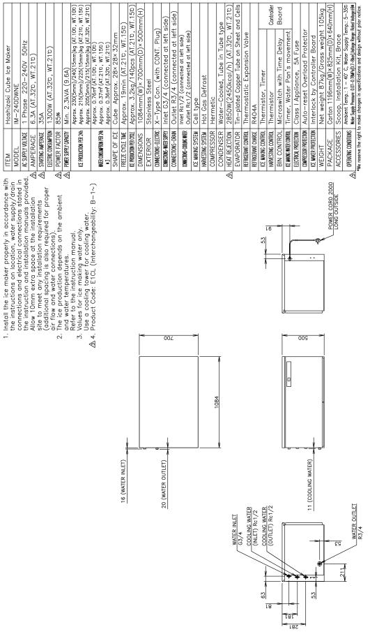
[a] IM-240DNE (Air-cooled) [Copeland compressor: auxiliary code B0 and earlier]

[b] IM-240DNE (Air-cooled) [Danfoss compressor: auxiliary code B1 and later]
2

[c] IM-240DNE-C (Air-cooled)
3

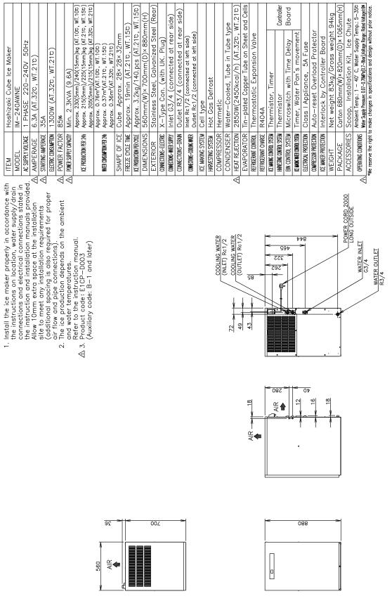
[d]IM-240DWNE (Water-cooled) [Copeland compressor: auxiliary code B0 and earlier]
[e] IM-240DWNE (Water-cooled) [Danfoss compressor: auxiliary code B1 and later]
5

[f] IM-240DWNE-C (Water-cooled)

[g] IM-240ANE (Air-cooled) [Copeland compressor: auxiliary code B0 and earlier]
7
[h] IM-240ANE (Air-cooled) [Danfoss compressor: auxiliary code B1 and later]
8

[i]IM-240AWNE (Water-cooled) [Copeland compressor: auxiliary code B0 and earlier]
9
[j] IM-240AWNE (Water-cooled) [Danfoss compressor: auxiliary code B1 and later]
10

[k] IM-240DSNE (Remote Air-cooled) [Danfoss Compressor]
11

[l] URC-240C-E-4 (Condenser Unit)
12
II. GENERAL INFORMATION
1. CONSTRUCTION
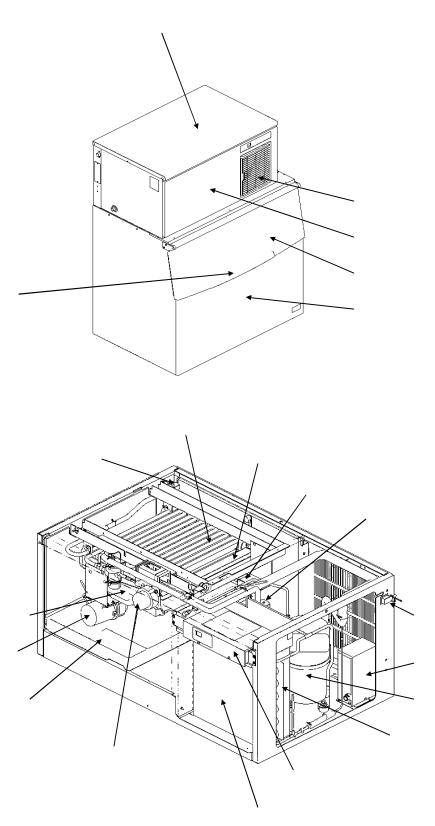
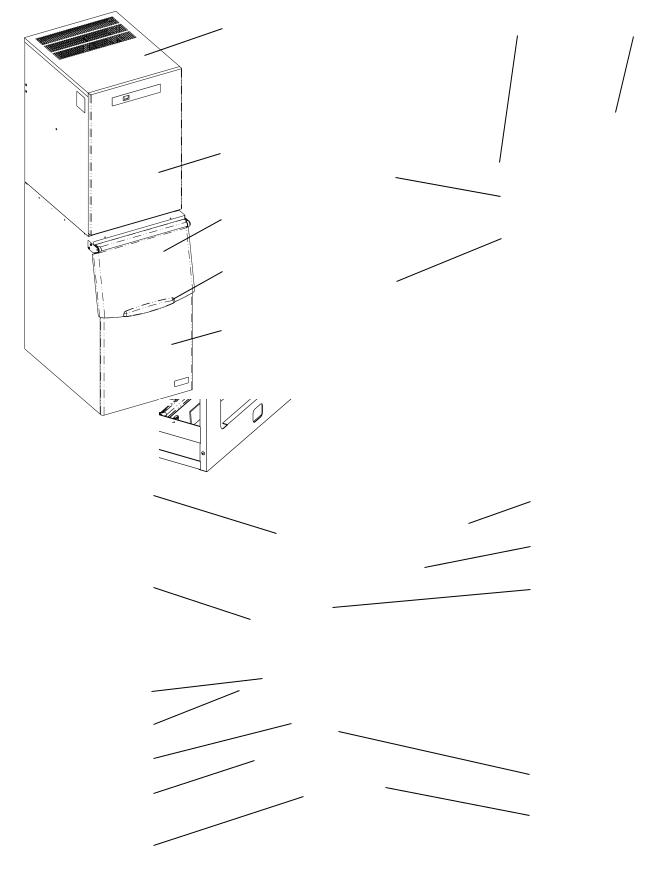
[a] IM-240DNE/XNE, IM-240DNE-C/XNE-C (Air-cooled)
Top Panel
Louver, Air Filter
Front Panel
Bin Door
Handle
Bin
Evaporator
Water Valve |
Water Plate |
Bin Control Switch
Hot Gas Valve
Water Tank |
Power Cord |
Pump Motor |
Control Box (B) |
|
|
Drain Pan |
Compressor |
Fan Motor
Actuator Motor
Control Box (A)
Air-Cooled Condenser
13

[b] IM-240DWNE/XWNE, IM-240DWNE-C/XWNE-C (Water-cooled)
Top Panel
Handle
Evaporator
Water Valve
Water Tank
Pump Motor
Drain Pan
Actuator Motor
Water-Cooled Condensor
Front Panel
Bin Door
Bin
Water Plate
Bin Control Switch
Hot Gas Valve
Power Cord
Water Regulator
Compressor
Control Box (A)
Control Box (B)
14
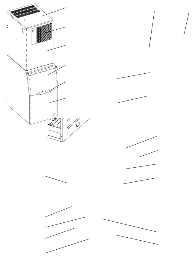
[c] IM-240ANE (Air-cooled)
Top Panel |
Nameplate |
|
Louver, Air Filter
Front Panel |
|
Bin Door |
|
Handle |
Water Valve |
|
|
Bin |
|
|
Drain Pipe |
|
Rear |
Front
Compressor
Hot Gas Valve
Fan Motor
Control Box |
Air-Cooled Condenser |
|
Evaporator 
Water Plate
Water Tank
Actuator Motor
Pump Motor
Bin Control Switch
Drain Pan
Front
15
[d] IM-240AWNE (Water-cooled)
Top Panel
Front Panel
Bin Door
Handle
Bin
Front
Power Cord |
Nameplate |
Cooling Water
Inlet
Cooling Water 
Outlet
Water Valve
Drain Pipe 
Rear
Water-Cooled Condenser |
Hot Gas Valve |
|
|
|
Water Regulator |
Control Box |
Compressor |
Evaporator
Water Plate
Water Tank
Actuator Motor
Pump Motor
Bin Control Switch
Drain Pan
Front
16

[e] IM-240DSNE (Remote Air-
Panel
Door
Water Valve
|
Evaporator |
Hot Gas Valve |
Power |
|
Fan Motor |
||
|
|
Wiring Cord |
Cord |
Pump |
|
Motor |
|
Actuator |
Access Valve |
Motor |
|
Control Box |
Dryer |
Starting Device |
Compressor |
|
Front
Drain Pan
Receiver Tank |
Bin Control |
Water Tank |
|
Drain Pipe |
|||
|
Switch |
||
|
|
Water Plate |
Rear
17
[f] URC-240C-E-4 (Condenser Unit)
Top Panel
Unit Cover
Service Valve
Cable Clamp
Condenser
CP Regulator
Fan Motor
Control Box
18

2. CONTROLLER BOARD
Note: Refer to the controller board service manual.
IMPORTANT
If receiving a service call, ask the user to turn off the power to the icemaker and turn it on again, while watching the icemaker. This will reset the controller, and in some cases normal operation will resume.
CAUTION
1.Check that the icemaker has been earthed properly. If not, the controller board will not work properly.
2.Do not change wiring and connections, or the controller board will not work properly.
3.Do not touch the reverse side of the controller board and tiny electronic devices on it.
4.Do not repair the electronic devices and parts on the controller board in the field (except for fuse replacement). Replace the whole board assembly when it fails.
5.To get static free, always touch the metal part of the icemaker before servicing. Electrostatic discharge will cause severe damage to the controller board.
6.The signal ground wire must be connected to the control box when replacing the controller board after service.
7.The controller board is fragile. Handle with care. * Do not drop the board on the floor.
*Make sure that the board is placed correctly into the guides in the control box. Mis-alignment could cause breakage when replacing the control box cover.
*Handle the board by the edges only. Do not touch the electric parts and devices.
19
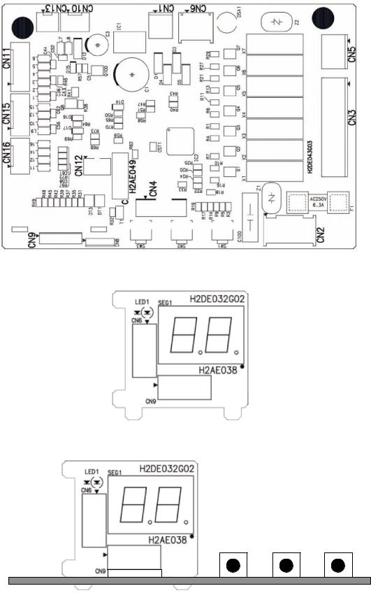
[a] CONTROLLER BOARD LAYOUT
Main Board
Sub Board
Combination
20
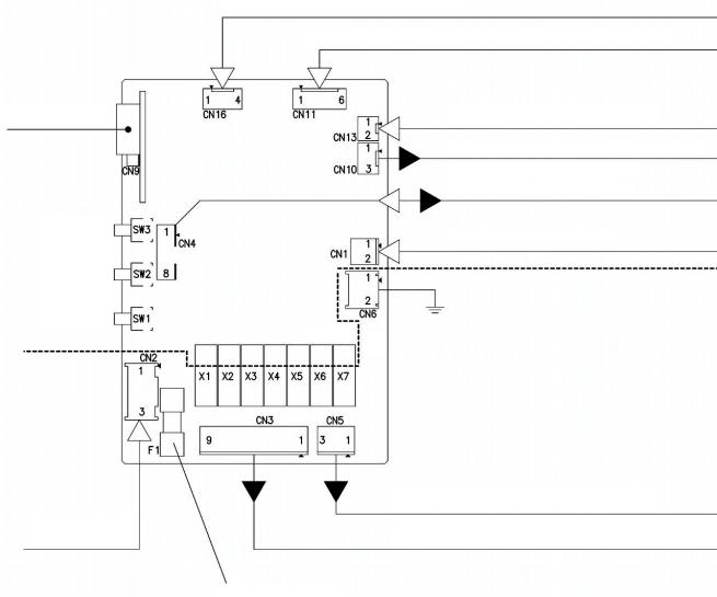
[b] INPUT/OUTPUT LAYOUT
|
Hall IC Input XA Connector (4P) |
|
|
|
Bin Control Switch / Pressure Switch / |
|
|
Condenser Thermistor Input XA Connector (6P) |
7-Segment Double- |
|
Cube Control Thermistor Input XA Connector (2P) |
Digit Display |
|
|
|
|
Data Input/Output PA Connector (8P) |
Reset Button |
|
10.5V AC Input VH Connector (2P) |
|
|
|
Close Button |
|
|
Open Button |
AC Low Voltage, |
AC High |
|
DC Circuit |
|
|
|
Voltage Circuit |
|
Actuator Drive Output VH Connector (3P) |
220-240V AC Input |
Pump Motor / Hot Gas Valve / Fan Motor / Water Valve / |
VYH Connector (3P) |
Compressor AC Relay Drive Output VH Connector (9P) |
|
Fuse |
|
P01992-01 |
|
6.3A |
21
[c] BEFORE CHECKING CONTROLLER BOARD
Check the power source voltage and the components as shown in the table below.
Component |
|
|
Procedure |
Normal |
||
|
|
|
|
|
|
|
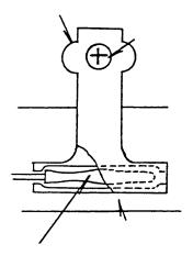
1. Thermistor |
|
|
CAUTION |
|
|
5 -7 kilohms |
|
|
|
|
|||
(on evaporator) |
|
Thermistor sensor part is fragile, |
|
|
||
|
|
glass sealed. Handle with care. |
|
|
||
|
|
|
|
|
|
|
|
* Disconnect the connector CN13 on |
|
||||
|
|
the board. |
|
|||
|
* Remove the screw and the |
|
||||
|
|
thermistor holder on the evaporator. |
|
|||
|
* Immerse the sensor part in a glass |
|
||||
|
|
containing ice and water for 5 |
|
|||
|
|
minutes. |
|
|||
|
* Check the resistance between CN13 |
|
||||
|
|
connector pins. |
|
|||
|
* Replace the thermistor in its correct |
|
||||
|
|
position. |
|
|||
|
* Connect CN13. |
|
||||
|
|
|
|
|
|
|
2. Bin Control Switch |
Manually set the micro switch in the |
Approx. |
||||
|
TRIP and RESET positions, and |
TRIP(Closed) 10 sec. |
||||
|
check the period. |
RESET(Open) 80 sec. |
||||
|
|
|
|
|
|
|
22
 Loading...