

Honda BF75 А, BF90 А Owner's Manual
WaNoH
S‘JauMo
~06 1 vSLdB
-IUItlkMU
pmuqq
California Proposition 65 Warning
WARNING: Engine Exhaust, some of its constituents, and certain vehicle components
contain or emit chemicals known to the State of California to cause cancer and birth
defects or other reproductive harm.
Keep this owner’s manual handy, so you can refer to it at any time. This owner’s manual
is considered a permanent part of the outboard motor and should remain with the outboard
motor if resold.
The information and specifications included in this publication were in effect at the time
of approval for printing. Honda Motor Co., Ltd. reserves the right, however, to discontinue
or change specifications or design at any time without notice and without incurring any
obligation whatever. No part of this publicatiqn may be reproduced without written
permission.
INTRODUCTION
Congratulations on your selection of
a Honda outboard motor. We are certain
you will be pleased with your purchase
of one of the finest outboard motors on
the market.
We want to help you get the best results
from your new outboard motor and to
operate it safely. This manual contains the
information on how to do that; please read
it carefully.
As you read this manual, you will
find information preceded by a
-1 symbol. That information is
intended to help you avoid damage to
your outboard motor, other property, or
the environment.
We suggest you read the warranty
policy to fully understand its coverage
and your responsibilities of ownership.
The warranty policy is a separate
document that should have been given
to you by your dealer.
When your outboard motor needs
scheduled maintenance, keep in mind that
your Honda marine dealer is specially
trained in servicing Honda outboard
motors. Your Honda marine dealer is
dedicated to your satisfaction and will be
pleased to answer your questions and
concerns.
0 2000 Honda Motor Co., Ltd.
All Right Reserved.
1
INTRODUCTION
A FEW WORDS ABOUT
SAFETY
Your safety and the safety of others are very
important. And using this outboard motor
safely is an important responsibility.
To help you make informed decisions
about safety, we have provided operating
procedures and other information on labels
and in this manual. This information alerts
you to potential hazards that could hurt
you or others.
Of course, it is not practical or possible
to warn you about all the hazards
associated with operating or maintaining
an outboard motor. You must use your own
good judgment.
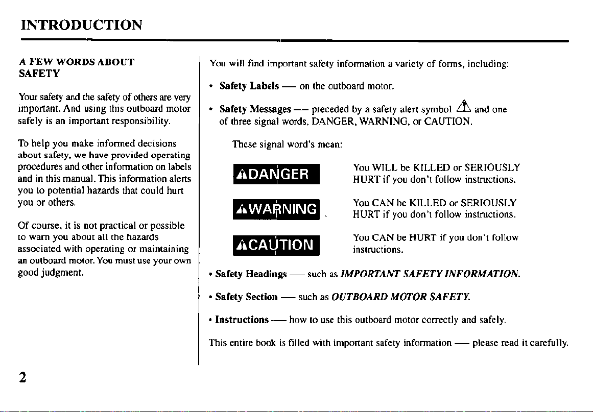
You will find important safety information a variety of forms, including:
l
Safety Labels - on the outboard motor.
A
l
Safety Messages - preceded by a safety alert symbol
and one
of three signal words, DANGER, WARNING, or CAUTION.
These signal word’s mean:
You WILL be KILLED or SERIOUSLY
HURT if you don’t follow instructions.
You CAN be KILLED or SERIOUSLY
HURT if you don’t follow instructions.
You CAN be HURT if you don’t follow
instructions.
l
Safety Headings - such as IMPORTANT SAFETY INFORMATION.
l
Safety Section - such as OUTBOARD MOTOR SAFETY.
l
Instructions -how to use this outboard motor correctly and safely.
This entire book is filled with important safety information - please read it carefully.
2
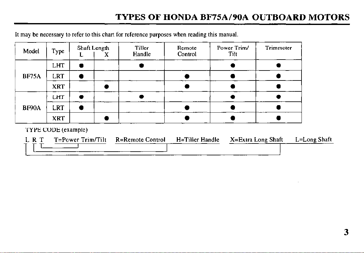
TYPES OF HONDA BF75A/90A OUTBOARD MOTORS
It may be necessary to refer to this chart for reference purposes when reading this manual
TYPE CODE (example)
LRT
UT
T=Power Trim/Tilt R=Remote Control
I
H=Tiller Handle
L=Long Shaft X=Extra Long Shalt
3
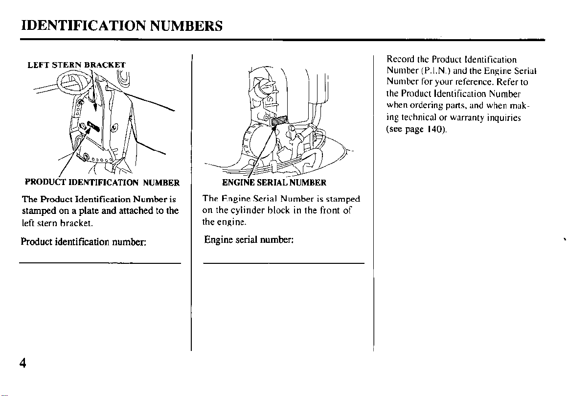
IDENTIFICATION NUMBERS
LEFTSTERNBRACKET
PRODUdT IDENTIFICATION NUMBER
The Product Identification Number is
stamped on a plate and attached to the
left stern bracket.
Product identification number:
Record the Product Identification
Number (P.I.N.) and the Engine Serial
Number for your reference. Refer to
the Product Identification Number
when ordering parts. and when mak-
ing technical or warranty inquiries
(see page 140).
ENGIN’E SERIAL NUMBER
The Engine Serial Number is stamped
on the cylinder block in the front of
the engine.
Engine serial number:
4
CONTENTS
1. OUTBOARD MOTOR SAFETY
Ih4PORTANTSAFETYINFORMATION.. . 7
SAFETY LABEL LOCATIONS ..... 9
2. COMPONENT IDENTIFICATION.. . 10
3. CONTROLS & INSTRUMENTS
TILLER HANDLE TYPE
Ignition Switch ........................ 16
Gear Shift Lever ...................... 16
Choke Knob.. ........................... 16
Throttle Grip.. .......................... 17
Throttle Opening Indicator.. .... 17
Throttle Friction Knob ............ 17
Engine Stop Switch ................. 18
Emergency Stop Switch Lanyard.. 18
Oil Pressure Indicator Light.. .. 19
Overheat Indicator Light ......... 19
Power Trim/Tilt Switch.. ......... 20
Steering Friction Adjuster ....... 20
REMOTE CONTROL TYPE
(SIDE-MOUNT TYPE)
Remote Control Lever ............. 21
Neutral Release Lever
.............
22
Ignition Switch ........................ 22
Emergency Stop Switch Lanyard.. 23
Choke/Fast Idle Lever ............. 24
Manual Choke Knob ............... 24
Oil Pressure Indicator Light/Buzzer.. 25
Overheat Indicator Light/Buzzer.. . 25
Power Trim/Tilt Switch..
.........
26
(PANEL-MOUNT TYPE)
Remote Control Lever ................
Neutral Release Lever ................
Ignition Switch ...........................
Emergency Stop Switch Lanyard
Throttle Button ...........................
Choke Switch .............................
Manual Choke Knob ..................
Oil Pressure Indicator Light/Buzzer.. ..
Overheat Indicator Light/Buzzer.. ....
Power Trim/Tilt Switch.. ............
(TOP-MOUNT TYPE)
Remote Control Lever ................
Ignition Switch ...........................
Emergency Stop Switch Lanyard
Throttle Button ...........................
Choke Switch .............................
Manual Choke Knob ..................
Oil Pressure Indicator Light/Buzzer.. ..
Overheat Indicator Light/Buzzer.. ....
Power Trim/Tilt Switch.. ............
COMMON
Power Tilt Switch (engine pan). .
Trim Meter .................................
Manual Relief Valve ..................
Tilt Lock Lever .............................
Trim Tab .....................................
Anodes Metal .............................
Cooling System Indicator.. ..........
Water Intakes.. ............................
27
;i
29
z:
30
31
31
32
33
34
35
36
36
36
i:
38
39
39
40
41
41
42
42
42
Transom Angle Adjusting Rod . . . 43
Fuel CaplGaugeNent Knob
(optional fuel tank) . . 44
Over-Rev Limiter . . . . . . . . . . . . . . . . . . . . 44
Engine Cover Lock Lever . . . . . . . 45
Fuel Hose Connector . . . . . . . . . . . . . . . 45
4. PRE-OPERATION CHECKS
Engine Cover Removal/Installation . . 46
Engine Oil . . . . .._........................ 47
Fuel Level (optional fuel tank) . . 48
Fuel Recommendations . . . . . . . . . . . 49
Oxygenated Fuels . . . . . . . . . . . . . . . . . . . . 50
Propeller/Cotter Pin Inspection . . . 5 1
Steering Friction Adjustment
(TILLER HANDLE TYPE) . . 52
Remote Control Friction
Adjustment . . . . . . . . . . . . . . . . . . . . . . . . . . . 52
Engine Cover Lock Lever
Adjustment . . . . . . . . . . . . . . . . . . . . . . . . . . . 53
Other Checks
l
Stern bracket . . . . . . . . . . . . . . . . . . . . . . . . . 54
l
Tool Kit . . . . . . . . . . . . . . . . . . . . . . . . . . . . . . . . . 54
9 Anodes . . . . . . . . . . . . . . . . . . . . . . . . . . . . . . . . . . 54
5. STARTING THE ENGINE
Optional Fuel Tank . . . . . . . . . . . . . . . . . . 55
Fuel Line Connection . . . . . . . . . . . . . . 55
STARTING THE ENGINE
(TILLER HANDLE TYPE) . . . . 57
5
CONTENTS
STARTING THE ENGINE
(REMOTECONTROLTYPE)...
(SIDE-MOUNT TYPE) . . . . . . . . . .
(PANEL-MOUNT TYPE) . . . . . .
(TOP-MOUNT TYPE) . . . . . . . . . . . .
STARTING THE ENGINE
(EMERGENCY
Troubleshooting Starting Problems
6. OPERATION
Break-in Procedure . . . . . . . . . . . . . . . . . .
TILLER HANDLE TYPE
Gear Shifting . . . . . . . . . . . . . . . . . . . . . . .
Steering . . . . . . . . . . . . . . . . . . . . . . . . . . . . . . . .
Cruising . . . . . . . . . . . . . . . . . . . . . . . . . . . . . . .
REMOTE CONTROL TYPE
(SIDE-MOUNT TYPE)
Gear Shifting . . . . . . . . . . . . . . . . . . . . . . .
Cruising . . . . . . . . . . . . . . . . . . . . . . . . . . . . . . .
(PANEL-MOUNT TYPE)
Gear Shifting . . . . . . . . . . . . . . . . . . . . . . .
Cruising . . . . . . . . . . . . . . . . . . . . . . . . . . . . . . .
(TOP-MOUNT TYPE)
Gear Shifting . . . . . . . . . . . . . . . . . . . . . . .
Cruising . . . . . . . . . . . . . . . . . . . . . . . . . . . . . . .
POWER TRIMfTILT
Power Trim/Tilt System . . . . . .
Trim Meter . . . . . . . . . . . . . . . . . . . . . . . . . .
Power Tilt Switch (engine pan) . . .
Manual Relief Valve . . . . . . . . . . .
Tilt Lock Lever
STARTING) .
. . . . . . . . . . . . . . . . . . . .
6
62
62
2;
71
76
77
78
78
81
80
81
82
83
84
85
86
88
i;
90
Trim Tab Adjustment . . . . . . . . 91
MOTORPROTECTIONSYSTEM
Engine Oil Pressure and
Overheat Warning System ...... 92
Over-Rev Limiter .................... 94
Anodes ..................................... 94
Shallow Water Operation ........... 95
High Altitude Operation ............. 96
7. STOPPING THE ENGINE
TILLER HANDLE TYPE.. ........ 97
REMOTE CONTROL TYPE
(SIDE-MOUNT TYPE) ............. 98
(PANEL-MOUNT TYPE) ......... 99
(TOP-MOUNT TYPE). ............ 100
8. TRANSPORTING ................... 101
9. CLEANING AND FLUSHING. 104
10. MAINTENANCE.. ................... 106
THE IMPORTANCE OF
MAINTENANCE .................. 106
MAINTENANCE SAFETY .... 106
EMISSION CONTROL
SYSTEM INFORMATION.. 107
STAR LABEL ..........................
Tool Kit and Spare Parts .......... 1 12
MAINTENANCE SCHEDULE.. . 113
Engine Oil ............................. 1 14
Gear Oil ................................. 1 17
Spark Plugs ............................ 1 18
Battery (not included). ........... 120
Lubrication ............................ 12 1
1 10
Engine Fuel Filter .................... 124
Fuel Tank and Filter ................
Fuse Replacement ................... 127
Propeller .................................. 128
Submerged Motor.. .................. 129
Il. STORAGE/WINTERIZATION . . 13 1
12. TROUBLESHOOTING ............. 135
13. SPECIFICATIONS .................... 137
14. WARRANTY SERVICE ........... 140
15. INDEX ....................................... 141
16. WIRING DIAGRAM ................. 144
126
1. OUTBOARD MOTOR SAFETY
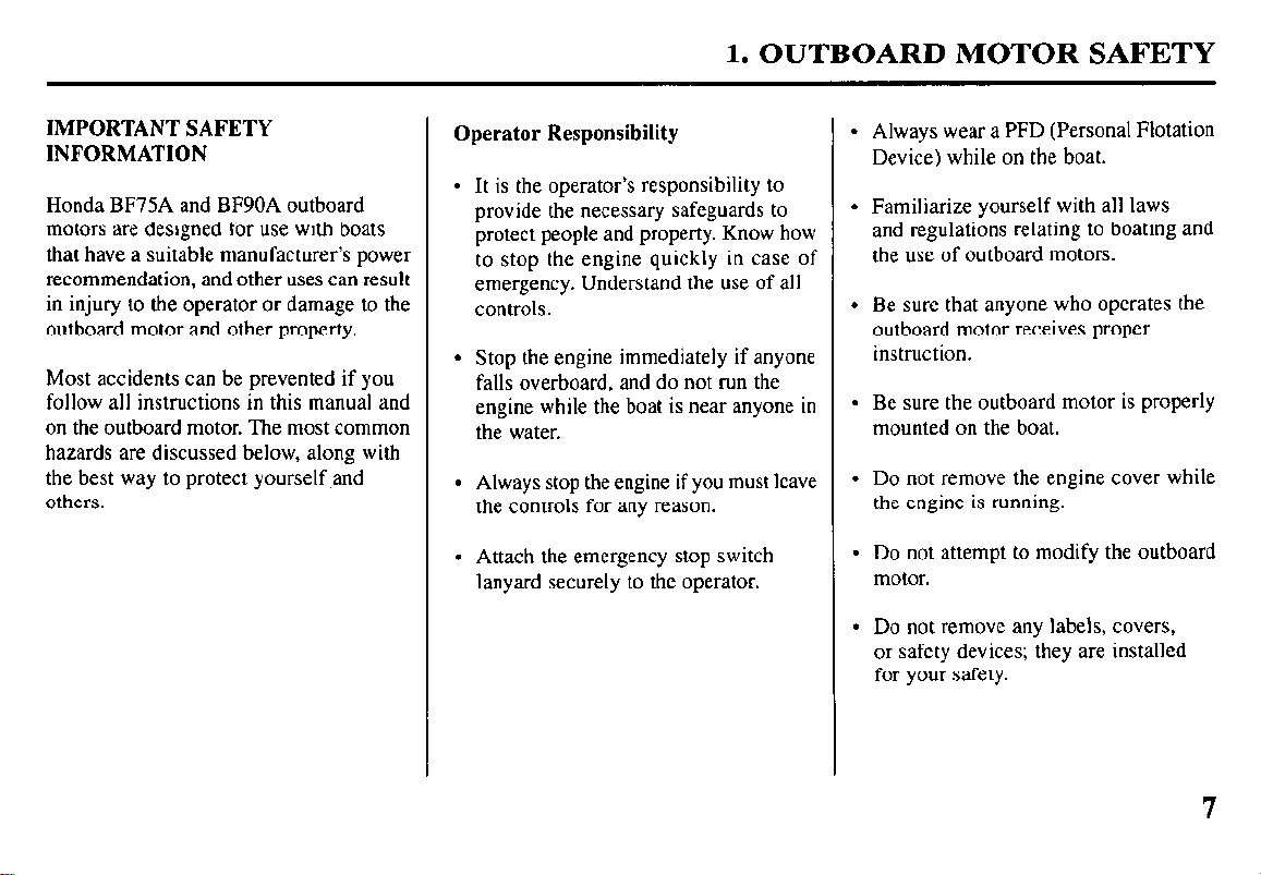
IMPORTANT SAFETY INFORMATION
Honda BF75A and BF90A outboard
motors are designed for use with boats
that have a suitable manufacturer’s power
recommendation, and other uses can result
in injury to the operator or damage to the
outboard motor and other property.
Most accidents can be prevented if you
follow all instructions in this manual and
on the outboard motor. The most common
hazards are discussed below, along with
the best way to protect yourself.and
others.
Operator Responsibility
l
It is the operator’s responsibility to
provide the necessary safeguards to
protect people and property. Know how
to stop the engine quickly in case of
emergency. Understand the use of all
controls.
l
Stop the engine immediately if anyone
falls overboard, and do not run the
engine while the boat is near anyone in
the water.
l
Always stop the engine if you must leave
the controls for any reason.
l
Attach the emergency stop switch
lanyard securely to the operator.
l
Always wear a PFD (Personal Flotation
Device) while on the boat.
l
Familiarize yourself with all laws
and regulations relating to boating and
the use of outboard motors.
l
Be sure that anyone who operates the
outboard motor receives proper
instruction.
l
Be sure the outboard motor is properly
mounted on the boat.
l
Do not remove the engine cover while
the engine is running.
l
Do not attempt to modify the outboard
motor.
l
Do not remove any labels, covers,
or safety devices; they are installed
for your safety.
1. OUTBOARD MOTOR SAFETY
Refuel With Care
l
Gasoline is extremely
flammable, and gasoline vapor can
explode. Refuel outdoors, in a
well-ventilated area, with the engine
stopped. Never smoke near gasoline, and
keep other flames and sparks away.
l
Remove any portable fuel tank from the
boat for refueling. Keep the portable fuel
tank away from the battery or other
potential spark sources.
l
Refuel carefully to avoid spilling fuel.
Avoid overfilling the fuel tank.
l
After refueling, tighten the filler cap
securely. If any fuel is spilled, make sure
the area is dry before starting the engine.
Carbon Monoxide Hazard
Exhaust gas contains poisonous carbon
monoxide. Avoid inhalation of exhaust gas.
Never run the engine in a closed garage or
confined area.
8
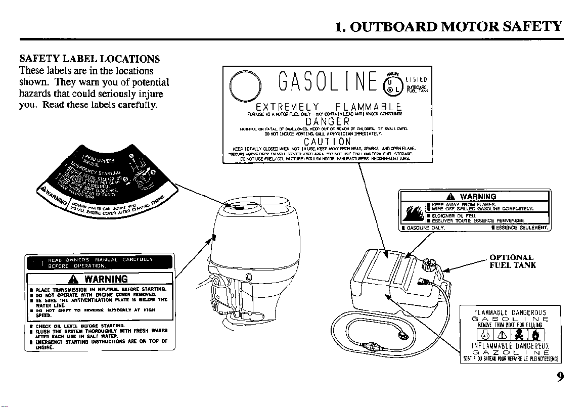
SAFETY LABEL LOCATIONS
These labels are in the locations
shown. They warn you of potentia1
hazards that could seriously injure
you. Read these labels carefully.
1. OUTBOARD MOTOR SAFETY
*PmmFELaL”-w”m*m4LEmhNr*KMM-
FLAMMABLE
DANGER
FUEL TANK
REWE FOR FI11ING
INFLAMMABLE DANGEREUX
GAZOL I NE
POBIIR UJ MW POURREFAIRE Lf FWN[YESSElU
9
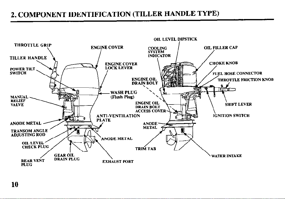
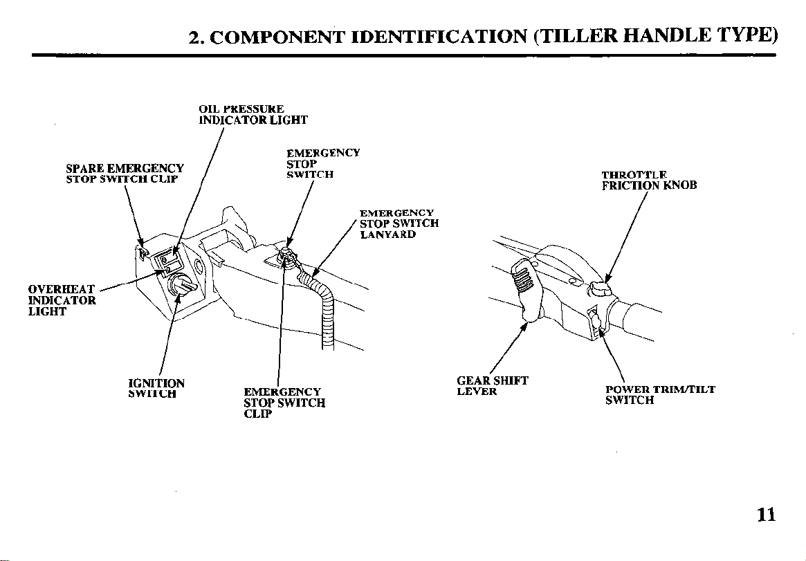
2. COMPONENT IDENTIFICATION (TILLER HANDLE TYPE)
OIL LEVEL DIPSTICK
THROTTLE GRIP
.%‘ITCIi
MANUAL
RELIEF
VALVE
ANODE METAL
TRANSOM ANG
ADJUSTING RO
REAR VENT
PLUG
10
/
GEAR OIL
DRAIN PLUG
/
ANTI-VENTILATION
TE
\
EXHAUST PORT
DRAIN BOLT
ACCESS cov
ANOD
META
EL HOSE CONNECTOR
LE FRICTION KNOB
SHIFT LEVER
liiNlTlON SWlTCH
\ WATER INTAKE
SPARE EMERGENCY
STOP SWITCH CLIP
OVERHEAT
~;~Z$TOR
2. COMPONENT IDENTIFICATION (TILLER
OIL PRESSURE
INDICATOR LIGHT
EMERGENCY
STOP
SWITCH
\
/
HANDLE TYPE)
THROTTLE
FRICTION KNOB
IGNITION
SWITCH
EMERGENCY
STOP SWITCH
CLIP
LEVER
;;yT:RHTRImILT
11
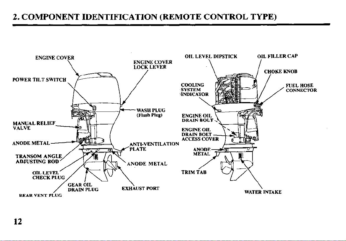
2. COMPONENT IDENTIFICATION (REMOTE CONTROL TYPE)
ENGINE COVER
\
POWER TILT SWITCH -f===
MANUAL RELIEF
VALVE
ANODE METAL
TRANSOM ANGL
ADJUSTING ROD
CHECK PLU
GEAR OIL
DRAIN PLUG
REAR VENT PiUG
/
12
ENGINE COVER
LOCK LEVER
/
WASH PLUG
(Flush Plug)
;z’T;ENTILATION
ANODE METAL
EXIikJST PORT
OIL LEVEL DIPSTICK
OIL FILLER CAP
WATER\INTAKE
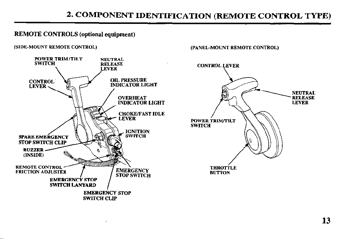
2. COMPONENT IDENTIFICATION (REMOTE CONTROL TYPE)
REMOTE CONTROLS (optional equipment)
(SIDE-MOUNT REMOTE CONTROL)
POWER TRIM/TILT
SWITCH
\
STOP SWITCH CLIP
REMOTE CONTROL
FRICTION ADJUSTE
SWITCH LANYARD
EMERGENCY STOP
SWITCH CLIP
NEUTRAL
RELEASE
LEVER
OVERHEAT
INDICATOR LIGHT
I
(PANEL-MOUNT REMOTE CONTROL)
CONTROL LEVER
SWITCH
THROTLE
BUTTON
NEUTRAL
RELEASE
LEVER
13
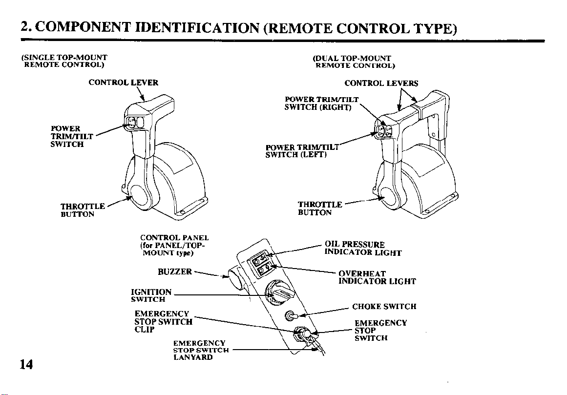
2. COMPONENT IDENTIFICATION (REMOTE CONTROL TYPE)
(SINGLE TOP-MOUNT
REMOTE CONTROL)
POWER
TRImILT ’
SWITCH
CONTROL PANEL
(for PANEL/TOP-
MOUNT type)
EMERGENCY
STOP SWITCH
(DUAL TOP-MOUNT
REMOTE CONTROL)
POWER TRIM/TILT
SWITCH (RIGHT)
POWER TRIM/TILT
SWITCH (LEFT)
THRoTTLE
BUTTON
CONTROL LEVERS
-
INDICATOR LIGHT
INDICATOR LIGHT
CHOKE SWITCH
EMERGENCY
14
EMERGENCY
STOP SWITCH
LANYARD
\
2. COMPONENT IDENTIFICATION
(COMMON)
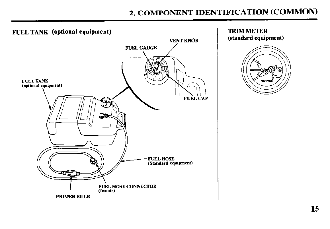
FUEL TANK (optional equipment)
FUEL TANK
(optional equipment)
FUEL HOSE CONNECTOR
I
PRIMERBULB
(female)
FUELGAUGE
FUEL
(Standard equipment)
VENTKNOB
/
HOSE
TRIM METER
(standard equipment)
15
3. CONTROLS (TILLER HANDLE TYPE)
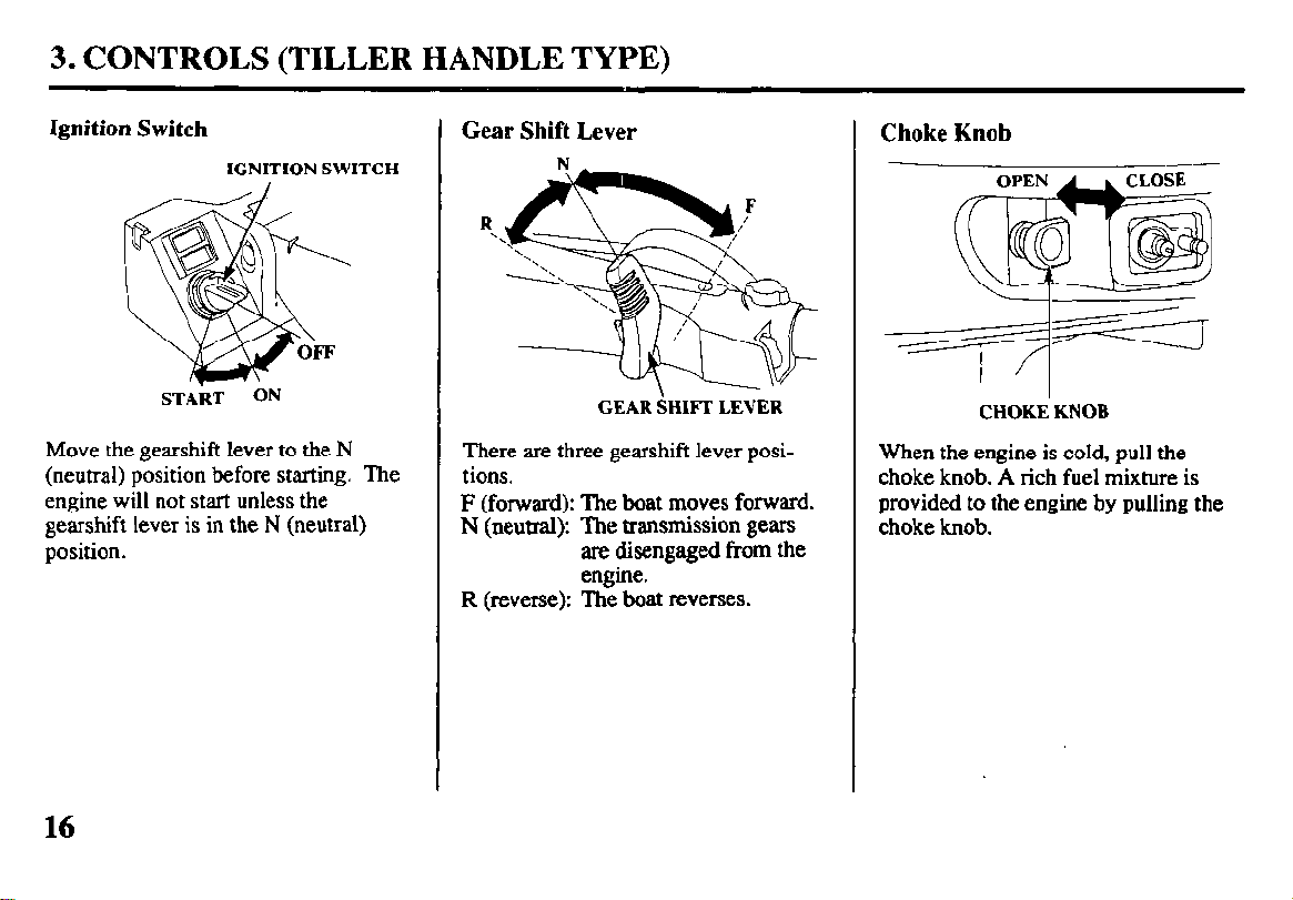
Ignition Switch
IGNITION SWITCH
START ON
Move the gearshift lever to the N
(neutral) position before starting. The
engine will not start unless the
gearshift lever is in the N (neutral)
position.
Gear Shift Lever
GEAR SHIFT LEVER
There arc three gearshift lever posi-
tions.
F (forward): The boat moves forward.
N (neutral): The transmission gears
are disengaged from the
engine.
R (reverse): The boat reverses.
Choke Knob
CHOKE KNOB
When the engine is cold, pull the
choke knob. A rich fuel mixture is
provided to the engine by pulling the
choke knob.
16
3. CONTROLS (TILLER HANDLE TYPE)
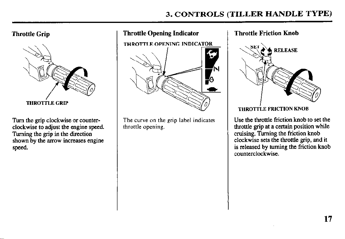
Throttle Grip
THROTTLE GRIP
Turn the grip clockwise or counter-
clockwise to adjust the engine speed.
Turning the grip in the direction
shown by the arrow increases engine
speed.
Throttle Opening Indicator
THROTTLE OPENING INDICATOR
The curve on the grip label indicates
throttle opening.
Throttle Friction Knob
THROTTiE FRICTION KNOB
Use the throttle friction knob to set the
throttle grip at a certain position while
cruising. Turning the friction knob
clockwise sets the throttle grip, and it
is released by turning the friction knob
counterclockwise.
17
3. CONTROLS (TILLER HANDLE TYPE)
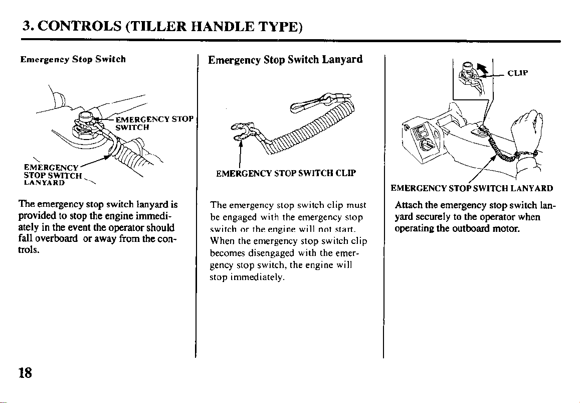
Emergency Stop Switch
EMERGENCY
;WITCH
ST01
\
EMERGENCY’
STOP SWITCH
LANYARD ‘x
The emergency stop switch lanyard is
provided to stop the engine immediately in the event the operator should
fall overboard or away from the controls.
Emergency Stop Switch Lanyard
EMERGENCY STOP SWITCH CLIP
The emergency stop switch clip must
be engaged with the emergency stop
switch or the engine will not start.
When the emergency stop switch clip
becomes disengaged with the emergency stop switch, the engine will
stop immediately.
CLIP
EMERGENCY STOP SWITCH LANYARD
Attach the emergency stop switch lanyard securely to the operator when
operating the outboard motor.
18
3. CONTROLS (TILLER
HANDLE TYPE)
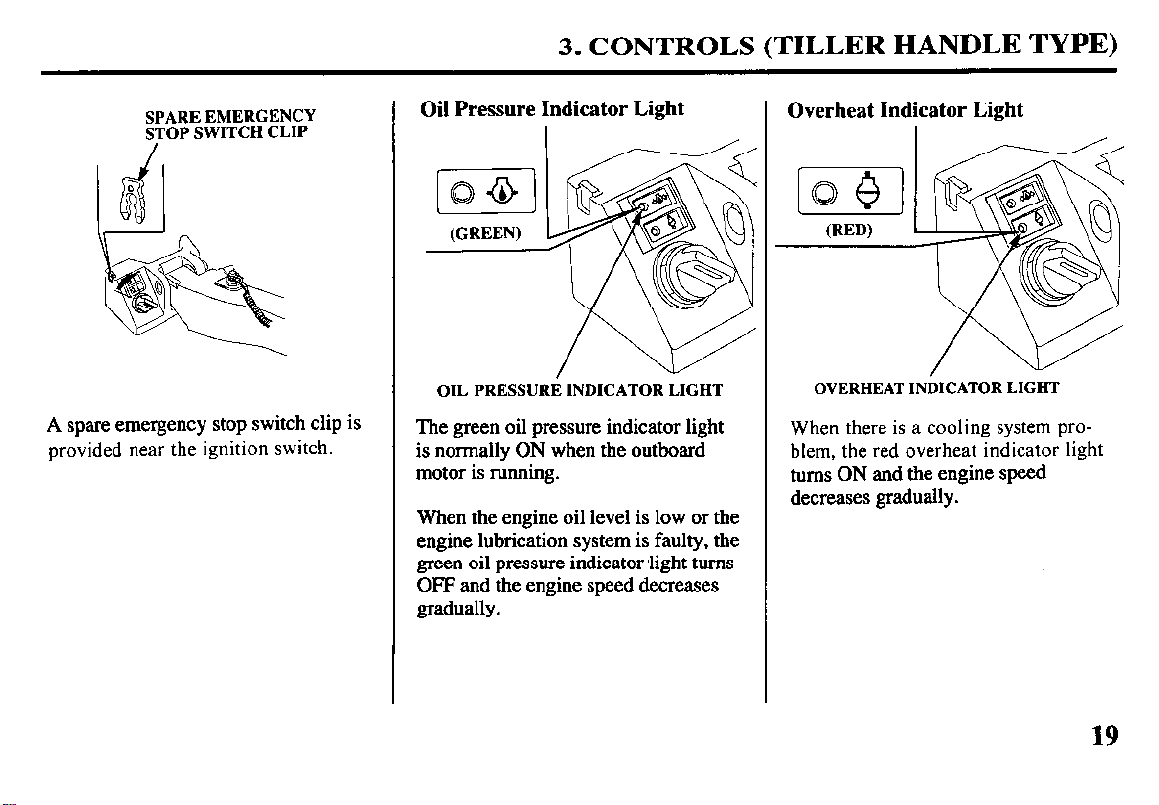
SPARE EMERGENCY
STOP SWITCH CLIP
A spare emergency stop switch clip is
provided near the ignition switch.
Oil Pressure Indicator Light
I /---l-K/
[o&l
(GREEN)
OIL PRESSURE INDICATOR LIGHT
The green oil pressure indicator light
is normally ON when the outboard
motor is running.
When the engine oil level is low or the
engine lubrication system is faulty, the
green oil pressure indicator <light turns
OFF and the engine speed decreases
gradually.
Overheat Indicator Light
OVERHEAT INDICATOR LIGHT
When there is a cooling system problem, the red overheat indicator light
turns ON and the engine speed
decreases gradually.
19
3. CONTROLS (TILLER HANDLE TYPE)
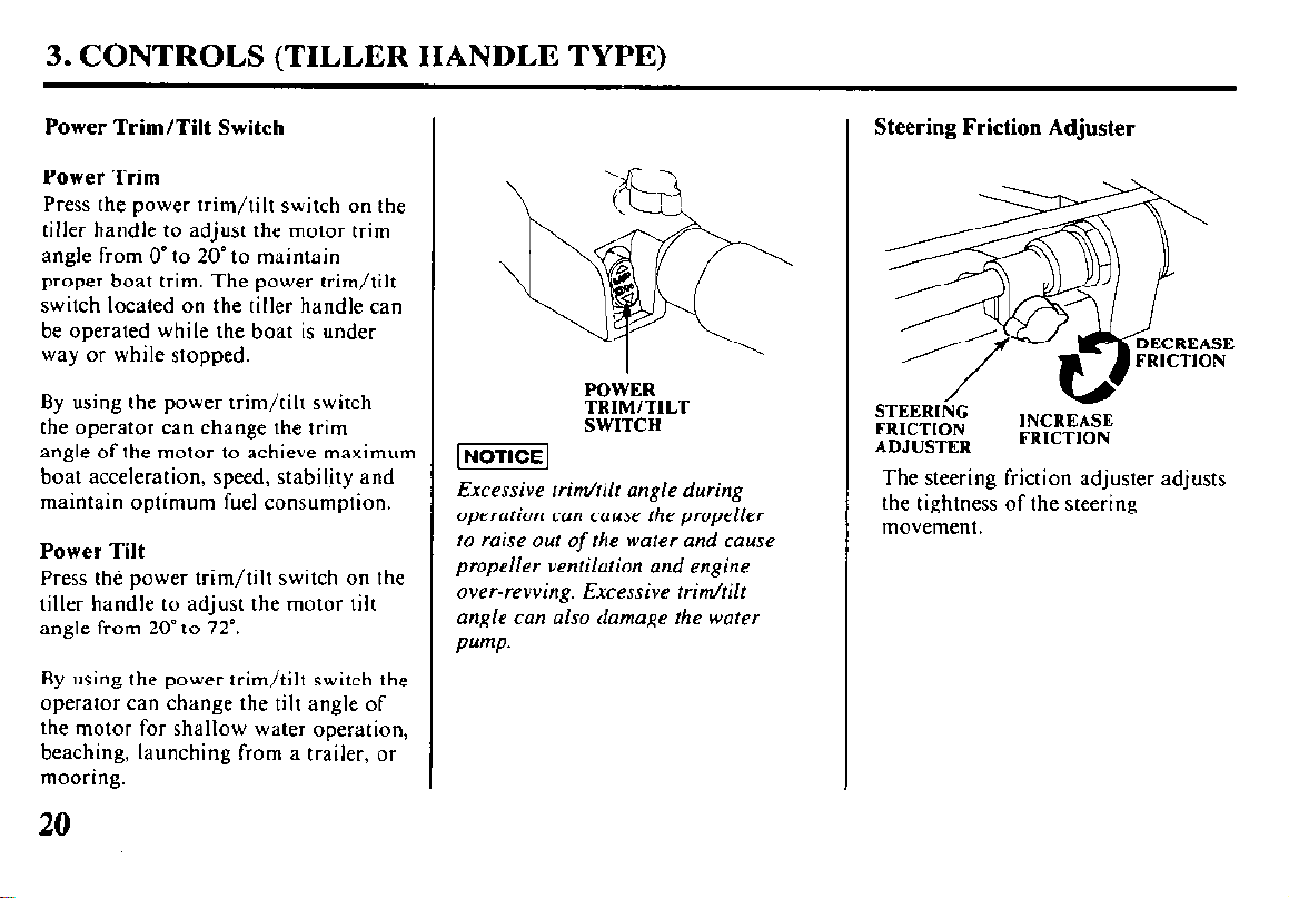
Power Trim/Tilt Switch
Power Trim
Press the power trim/tilt switch on the
tiller handle to adjust the motor trim
angle from 0” to 20” to maintain
proper boat trim. The power trim/tilt
switch located on the tiller handle can
be operated while the boat is under
way or while stopped.
By using the power trim/tilt switch
the operator can change the trim
angle of the motor to achieve maximum
boat acceleration, speed, stability and
maintain optimum fuel consumption.
Power Tilt
Press tht? power trim/tilt switch on the
tiller handle to adjust the motor tilt
angle from 20” to 72”.
By using the power trim/tilt switch the
operator can change the tilt angle of
the motor for shallow water operation,
beaching, launching from a trailer, or
mooring.
POWER TRIM/TILT SWITCH
[ NOTlCEl
Excessive trim/tilt angle during
operation can cause the propeller
to raise out
of
the water and cause
propeller ventilation and engine
over-revving. Excessive trim/tilt
angle can also damage the water
Pump.
Steering Friction Adjuster
STEERING FRICTION ADJUSTER
INCRE ’
FRICT
&E
ION
The steering friction adjuster adjusts
the tightness of the steering
movement.
20
3. CONTROLS (REMOTE
CONTROL TYPE)
(SIDE-MOUNT TYPE)
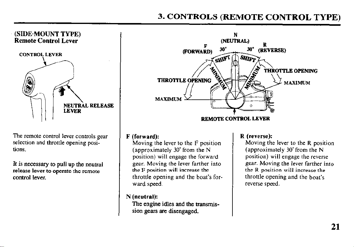
Remote Control Lever
CONTROI; LEVER
RELEASE
The remote control lever controls gear
selection and throttle opening positions.
It
is necessary to pull up
the neutral
release lever to operate the remote
control lever.
THROTI’LE Oi’IiNING
MAXIMUM v
REMOTE CONTROL LEVER
F
(forward):
Moving the lever to the F position
(approximately 30” from the N
position) will engage the forward
gear. Moving the lever farther into
the F position will increase the
throttle opening and the boat’s forward speed.
N (neutral):
The engine idles and the transmission gears are disengaged.
N
(NEUTRAL) R
%k
wuqy
,/o 1,
R
$!j& 9 MAXIMUM
(reverse):
Moving the lever to the R position
(approximately 30” from the N
position) will engage the reverse
gear. Moving the lever farther into
the R position will increase the
throttle opening and the boat’s
reverse speed.
21
3. CONTROLS (REMOTE CONTROL TYPE)
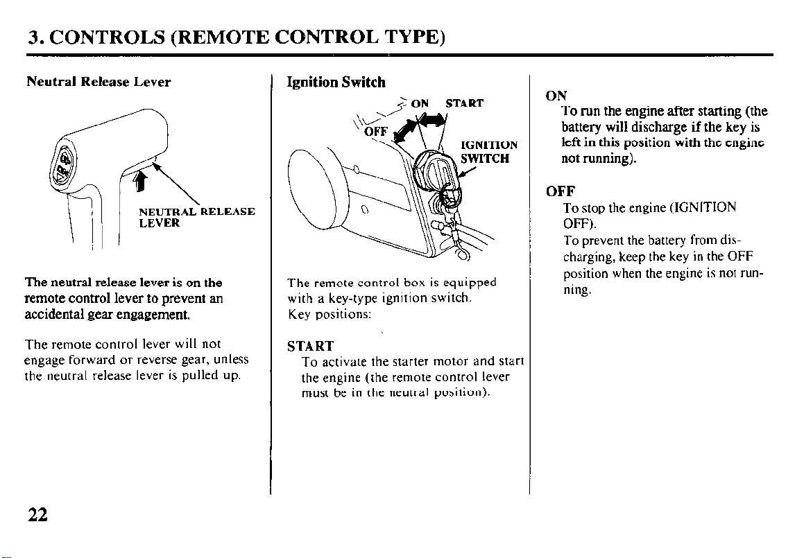
Neutral Release Lever
The neutral release lever is on the
remote control lever to prevent an
accidental gear engagement.
The remote control lever will not
engage forward or reverse gear, unless
the neutral release lever is pulled up.
Ignition Switch
=? ON START
The remote control box is equipped
with a key-type ignition switch.
Key positions:
START
To activate the starter motor and start
the engine (the remote control lever
must be in the neutral position).
ON
To run the engine after starting (the
battery will discharge if the key is
left in this position with the engine
not running).
OFF
To stop the engine (IGNITION
OFF).
To prevent the battery from dis-
charging, keep the key in the OFF
position when the engine is not running.
22
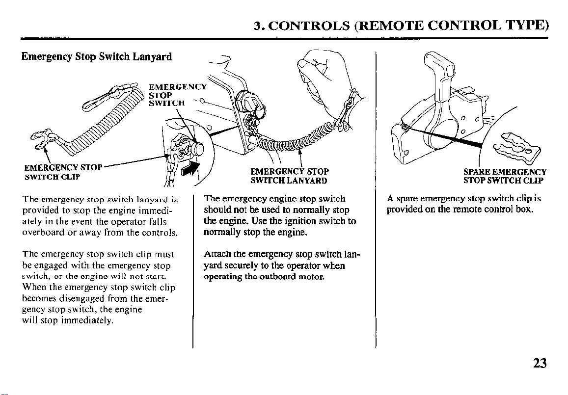
Emergency Stop Switch Lanyard
EMERGENCY
3. CONTROLS (REMOTE CONTROL TYPE)
The emergency stop switch lanyard is
provided to stop the engine immediately in the event the operator falls
overboard or away from the controls.
The emergency stop switch clip must
be engaged with the emergency stop
switch, or the engine will not start.
When the emergency stop switch clip
becomes disengaged from the emergency stop switch, the engine
will stop immediately.
Y
The emergency
SWITCH LANYARD
engine
stop switch
should not he used to normally stop
the engine. Use the ignition switch to
normally stop the engine.
Attach the emergency stop switch lanyard securely to the operator when
operating the outboard motor.
SPARE EMERGENCY
STOP SWITCH CLIP
A spare emergency stop switch clip is
provided on the remote control box.
23
3. CONTROLS (REMOTE CONTROL TYPE)
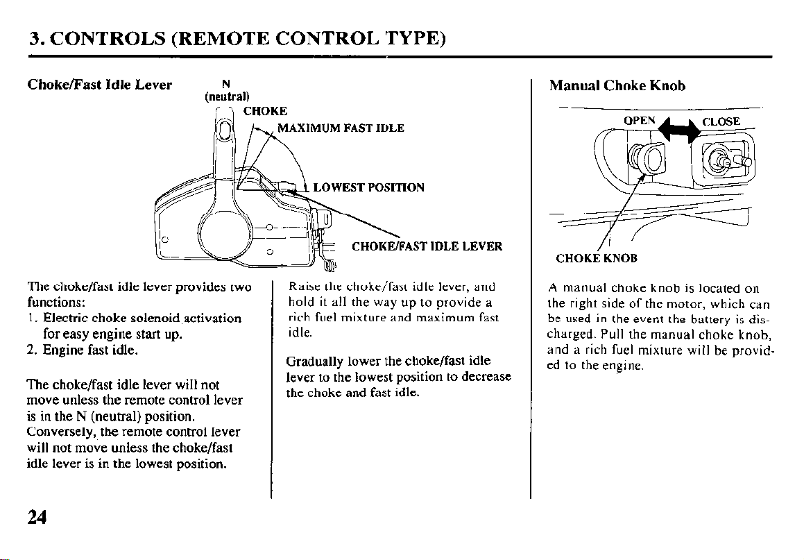
Choke/Fast Idle Lever
N
(neutral)
,(-’ CHOKE
The choke/fast idle lever provides two
functions:
1. Electric choke solenoid activation
for easy engine start up.
2. Engine fast idle.
The choke/fast idle lever will not
move unless the remote control lever
is in the N (neutral) position.
Conversely, the remote control lever
will not move unless the choke/fast
idle lever is in the lowest position.
AXIMUM FAST II)LE
EST POSITION
’ IDLE LEVER
Raise the choke/fast idle lever, and
hold it all the way up to provide a
rich fuel mixture and maximum fast
idle.
Gradually lower the choke/fast idle
lever to the lowest position to decrease
the choke and fast idle.
Manual Choke Knob
CHOKE KNOB
A manual choke knob is located on
the right side of the motor, which can
be used in the event the battery is discharged. Pull the manual choke knob,
and a rich fuel mixture will be provided to the engine.
24
3. CONTROLS (REMOTE CONTROL TYPE)
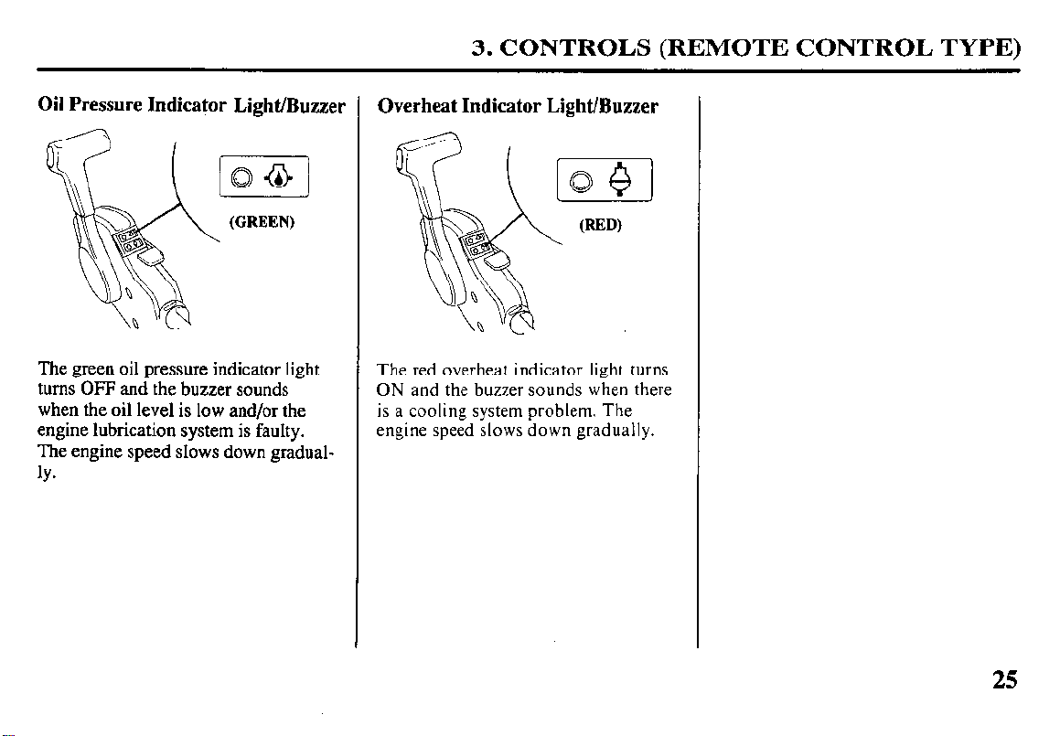
Oil Pressure Indicator Light/Buzzer
The green oil pressure indicator light
turns OFF and the buzzer sounds
when the oil level is low and/or the
engine lubrication system is faulty.
The engine speed slows down gradual-
ly*
Overheat Indicator Light/Buzzer
io$l
(RED)
\
The red overheat indicator light turns
ON and the buzzer sounds when there
is a cooling system problem. The
engine speed slows down gradually.
25
3. CONTROLS (REMOTE CONTROL TYPE)
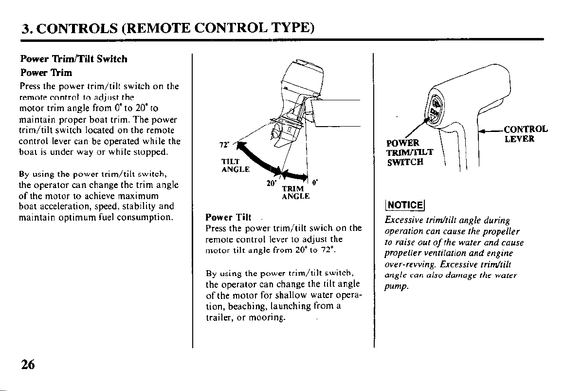
Power ‘kim/Tilt Switch
Power @Mm
Press the power trim/tilt switch on the
remote control to adjust the
motor trim angle from 0’ to 20” to
maintain proper boat trim. The power
trim/tilt switch located on the remote
control lever can be operated while the
boat is under way or while stopped.
By using the power trim/tilt switch,
the operator can change the trim angle
of the motor to achieve maximum
boat acceleration, speed, stability and
maintain optimum fuel consumption.
Power Tilt
Press the power trim/tilt swich on the
remote control lever to adjust the
motor tilt angle from 20” to 72”.
By using the power trim/tilt switch,
the operator can change the tilt angle
of the motor for shallow water operation, beaching, launching from a
trailer, or mooring.
TRIM
ANGLE
Excessive trim/tilt angle during
operation can cause the propeller
to raise out
propeller ventilation and engine
over-revving. Excessive trim/tilt
angle can also damage the water
Pump.
of
the water and cause
26
3. CONTROLS (REMOTE CONTROL TYPE)
(PANEL-MOUNT TYPE)
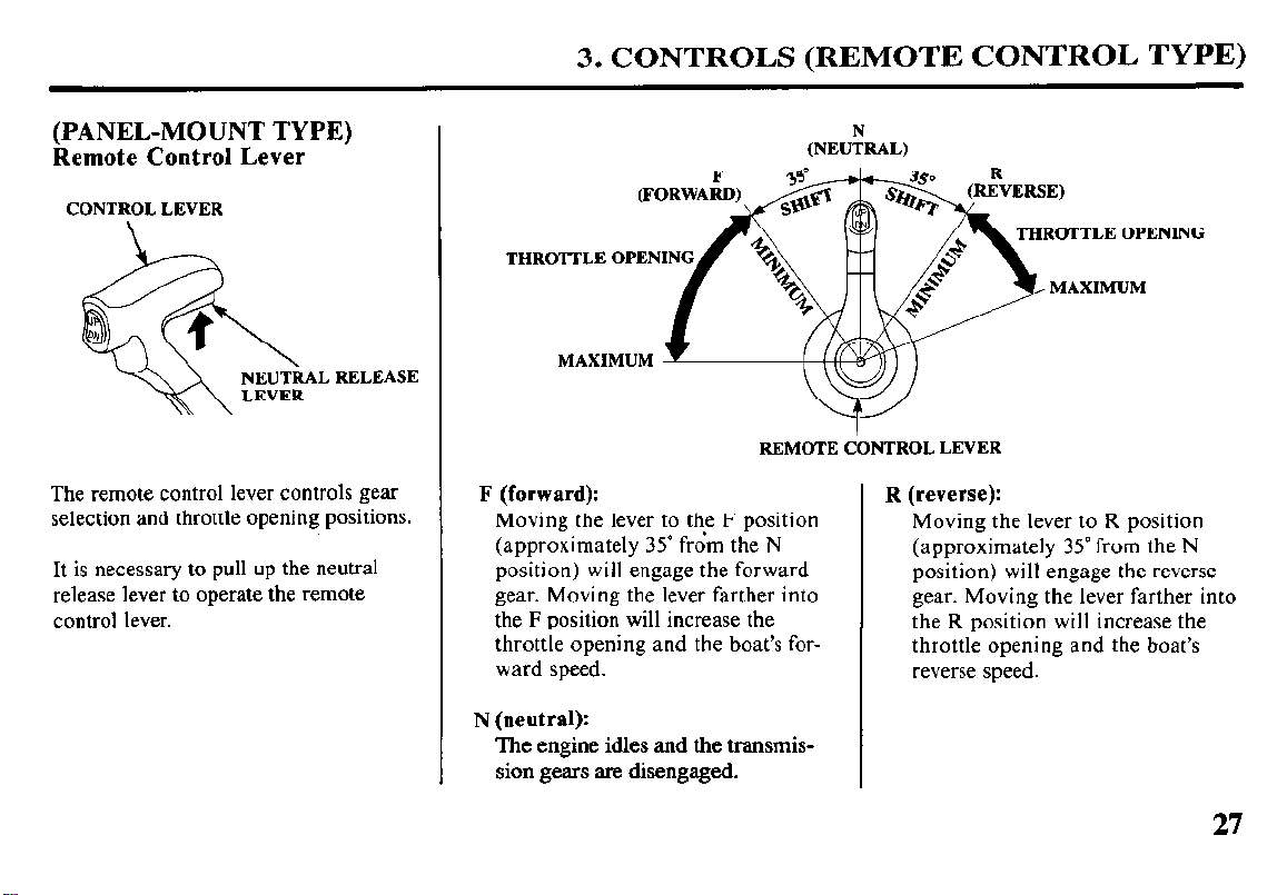
Remote Control Lever
CONTROL LEVER
The remote control lever controls gear
selection and throttle opening positions.
It is necessary to pull up the neutral
release lever to operate the remote
control lever.
THROTTLE OPENING
REMOTE CONTROL LEVER
F (forward):
Moving the lever to the F position
(approximately 35” from the N
position) will engage the forward
gear. Moving the lever farther into
the F position will increase the
throttle opening and the boat’s forward speed.
N (neutral):
The engine idles and the transmission gears are disengaged.
(NE&&AL)
THROTTLE OPENING
R (reverse):
Moving the lever to R position
(approximately 35” from the N
position) will engage the reverse
gear. Moving the lever farther into
the R position will increase the
throttle opening and the boat’s
reverse speed.
27
3. CONTROLS (REMOTE CONTROL TYPE)
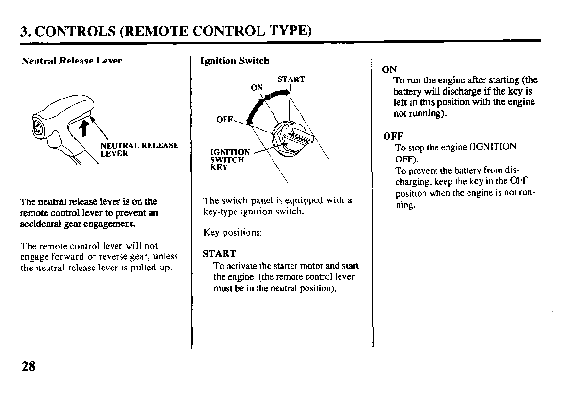
Neutral Release Lever
The neutral release lever is on the
remote control lever to prevent an
accidental gear engagement.
The remote control lever will not
engage forward or reverse gear, unless
the neutral release lever is pulled
up.
Ignition Switch
START
The
switch panel is equipped with a
key-type ignition switch.
Key positions:
START
To
activate the starter motor and start
the engine (the remote control lever
must be in the neutral position).
ON
To run the engine after starting (the
battery will discharge if the key is
left in this position with the engine
not running).
OFF
To
stop the engine
(IGNITION
OFF).
To prevent the battery from dis-
charging, keep the key in the
position when the engine is not running.
OFF
28
 Loading...