

Page 1
SM6T2 DISHWASHER
MODEL
SM6T2
SM6T2 ML-110857
701 S. RIDGE AVENUE
TROY, OHIO 45374-0001
937 332-3000
www.hobartcorp.com
FORM 34047 Rev. A (July 2000)
Page 2
Installation, Operation, and Care of
MODEL SM6T2 DISHWASHER
SAVE THESE INSTRUCTIONS
GENERAL
The SM6T2 dishwasher is an electrically controlled, semi-automatic, rack type dishwasher with
telescoping hoods, designed for straight-through operation. The wash and rinse cycles are timed and
automatically controlled. The timed rinse cycle operates a solenoid valve. The wash pump motor is
1
rated
available in durable plastic, pegged or flat-bottomed. A vacuum breaker is provided on the rinse and
fill line which provides an air gap to prevent any reverse flow of water from the machine into the potable
water supply.
/2 HP. The wash tank heater is rated 1000 watts. The dishwasher accommodates 16" x 16" racks,
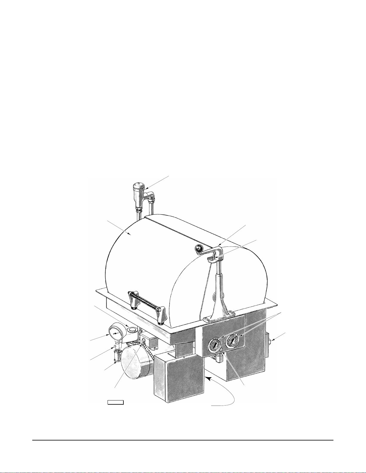
MODEL SM6T2 DISHWASHER
VACUUM BREAKER
SOLENOID
VALVE
WATER
PRESSURE GAUGE
PETCOCK
VALVE
FILL CONNECTION
HOOD
JUNCTION BOX
CONTROL HANDLE
INTERLOCK
THERMOMETERS
THERMOSTAT
PILOT LIGHT
© HOBART CORPORATION, 1998
PL-53053
CONTROL SWITCH
MANUAL-AUTO
Fig. 1
– 2 –
Page 3

INSTALLATION
Immediately after unpacking the dishwasher, check for possible shipping damage. If the machine is
found to be damaged, save the packaging material and contact the carrier within 15 days of delivery.
Prior to installation, test the electrical service to make sure it agrees with the specifications on the
machine data plate.
LOCATION AND LEVELING
The dishwasher must be installed per the drawings on pages 4 – 6. Stainless steel is the recommended
material for the table. The table should be a convenient height for the operator. The dishwasher should
be level, both front-to-back and side-to-side. The table should drain into the dishwasher. Seal around
the table flange with an NSF approved sealer.
PLUMBING CONNECTIONS
WARNING: PLUMBING CONNECTIONS MUST COMPLY WITH APPLICABLE SANITARY, SAFETY,
AND PLUMBING CODES.
The plumber who connects this machine is responsible for making certain that incoming water lines are
THOROUGHLY FLUSHED OUT before connecting to any manual valve or solenoid valve.
This "flush-out" is necessary to remove all foreign matter, such as chips (resulting from cutting or
threading of pipes), pipe joint compound from the lines, or, if soldered fittings are used, bits of solder
or cuttings from tubing. Debris, if not removed, may lodge in the valves and render them inoperative.
Manual valves or solenoid valves fouled by foreign matter, and any expenses resulting from this
fouling, are NOT the responsibility of the manufacturer.
Hot Water Connection
Water must be proper hardness. Recommended hardness range is 4 – 6 grains / gallon. Lower
hardness can promote corrosion, higher hardness may cause excessive formation of lime scale. A line
strainer should be installed in the water supply line at the time of installation. The line strainer prevents
frequent clogging of the rinse nozzles and requires only occasional cleaning.
1
The water supply connection point has a
/2" NPT internal thread (see FILL CONNECTION, Fig. 1). The
water supplied to this machine must be 180°F and have a flow pressure of 20 – 25 psig for most effective
rinsing. CAUTION: The water pressure regulator must have a relief by-pass. Failure to use the
proper type of pressure regulator may result in damage to the unit. After installation, a pressure
gauge must be visible and access must be available to service connections and areas which require
cleaning.
Drain Connection
1
Connect the drain to the sewer from the 1
1
coupling to provide 1
/2" line to sewer. If a grease trap is required by code, it should have a minimum
/4" NPT tapped connection, provided. Use a 11/4" – 11/2"
flow capacity of approximately 28 gallons per minute.
ELECTRICAL CONNECTIONS
WARNING: ELECTRICAL AND GROUNDING CONNECTIONS MUST COMPLY WITH APPLICABLE
PORTIONS OF THE NATIONAL ELECTRICAL CODE AND/OR OTHER LOCAL ELECTRICAL CODES.
WARNING: DISCONNECT THE ELECTRICAL POWER SUPPLIES AND PLACE A TAG AT THE
DISCONNECT SWITCHES INDICATING THAT YOU ARE WORKING ON THE CIRCUITS.
Make the main electrical connection at the motor junction box (Fig. 1) where a knockout for 1/2" conduit
is provided. Make the electrical connection for the electric heater circuit at the electric box for the
1
electric heater where a knockout for
/2" conduit is provided. Refer to the wiring diagram attached to
the inside of the control box cover. All electrical supply lines to the machine must be disconnected
when disconnection is required.
– 3 –
Page 4

– 4 –
Page 5

– 5 –
Page 6

– 6 –
Page 7

OPERATION
INTERLOCK
The hoods are interlocked with the Control Handle (Fig. 1) which prevents operation of the automatic
wash and rinse cycle with a hood open. Also, the hoods cannot be opened while the dishwasher is in
an automatic wash and rinse cycle.
FILLING THE TANK
Be sure that the Overflow Pipe (Fig. 3) is properly seated. Then close the hood and turn the Control
Handle to the rinse position (Fig. 2). Hold it there until the wash tank is filled to the top of the Overflow
Pipe.
DETERGENT
Use only commercial grade detergents recommended by your chemical professional. Do not use
detergents formulated for residential dishwashers. Contact your chemical supplier to obtain a
recommendation for an appropriate detergent that is suited to the water in your locality.
The wash tank capacity is 5 gallons. Rinse water usage adds 1.36 gallons of fresh water per cycle at
20 psig.
HEATER
The electric heater with thermostat (standard) must also have a fused disconnect switch (not provided)
installed in the electric service line supplying this device and should meet the requirements of your local
electrical code. The switch must be placed in a convenient location for the operator. To operate the
heater, set the dial on the thermostat to the desired water temperature.
The heater should be turned on and off by the disconnect switch and not by the thermostat dial. If the
thermometer does not indicate the proper temperature with the pump running, the thermostat can be
set higher or lower as required.
CAUTION: Be sure the tank is filled with water before turning on the heater and always turn off
the heater before draining the tank.
NOTE: Should the tank be accidentally drained before turning off the heater, the thermostat will
automatically shut off the heater. When this type of heater shut-off occurs, turn off the power at the
disconnect switch. Allow the thermostat bulb to cool. Fill the tank with water. Press the small re-set
button next to the control knob on the thermostat. Then, turn on the power at the disconnect switch.
PREPARATION
•Make sure the dishwasher tank, the Strainer
Pans and the chamber are clean.
•With the Overflow Pipe properly seated, fill
the tank to the top of the Overflow Pipe by
turning and holding the Control Handle in
the rinse position (Fig. 2).
IN
RACK
WASH
RINSE
•Put Strainer Pans (Fig. 3) in place. Scatter
the initial charge of detergent over the
Strainer Pans.
•Turn the heater on. Wash water temperature
should be 150°F.
Fig. 2
PL-53056
– 7 –
Page 8

AUTOMATIC DISHWASHING
PL-53054
OVERFLOW PIPE
STRAINER PAN
Pre-scrap dishes thoroughly to remove large food particles and debris. Never use steel wool on ware
that is to be loaded into the dishwasher.
Do not allow foreign objects to enter the dishwasher, especially metallic contaminants.
Stack the dishes in a rack. Do not stack dishes one on
top of another as water must have free access to all sides
of every dish. Stand plates and dishes up edgewise as
shown in Fig. 2. Cups, glasses, and bowls should be
inverted in an open-type or compartment type rack.
Silverware and other small pieces may be scattered
loosely over the bottom of a flat bottom rack.
Open the hood and slide in a rack of dishes. Have the
rack turned so the plates stand at right angles to the edge
of the table (Fig. 2). Close the hood. With the Control
Switch turned to the Auto position and the hoods closed,
turn the Control Handle to ON and the timer motor will
start.
The timer then lights the Pilot Light and starts the pump
motor. The Pilot Light (Fig. 1) stays on until the cycle is
completely finished. The wash pump operates for 73
seconds, then stops. A pause of 3 seconds follows to
allow the wash water to drain from the dishes. Then, the
rinse solenoid comes on for 12 seconds to complete the
88 second timed cycle. When the rinse shuts off, the Pilot
Fig. 3
Light goes out. Turn the Control Handle to neutral.
If your tables are arranged for straight through operation, open the opposite hood, and slide the rack
out on the clean dish table.
Allow clean dishes to drain and air-dry before removing from rack.
Add dishwashing detergent at regular intervals to replace that consumed in the wash / rinse process,
as recommended by your chemical supplier.
The Control Switch (Fig. 1) in the center position (between Manual and Auto) provides only a Manual
Rinse (or Fill) operation — if the Control Handle is turned to Rinse (Fig. 2).
MANUAL OPERATION
With the Control Switch turned to the Manual position, the auxiliary circuit allows the dishwasher to
operate manually using the Control Handle in the Wash and Rinse positions (Fig. 2). The same 73
second wash, 3 second pause, and 12 second rinse cycles should be used when the dishwasher is
operated manually as when operated by the automatic timer.
AFTER WASHING
• Turn the heater OFF.
• Remove the Strainer Pans (Fig. 3) and empty contents into garbage can or disposer.
• Lift out the Overflow Pipe (Fig. 3) and let the water drain out.
– 8 –
Page 9

CLEANING
WARNING: DISCONNECT THE ELECTRICAL POWER SUPPLIES BEFORE CLEANING OR
SERVICING THIS MACHINE.
The machine must be thoroughly cleaned at the end of each working shift, or at least twice a day. Use
only products formulated to be safe on stainless steel.
Wash Arm
The Wash Arm can usually be cleaned without removing it from the dishwasher. Swing up the Wash
Arm End Covers (Fig. 4) and flush out by closing the hood and operating the wash manually. (Refer
to Manual Operation, page 8.)
To remove the Wash Arm from the machine, lift off the Rinse Arm and unscrew the Rinse Arm Bearing
Pin (Fig. 4) on which the Rinse Arm rotates. This may be done by inserting a rod in the cross holes
to serve as a wrench.
If the arm should stop revolving, first make sure that the tank is full of water. Then make sure that all
wash arm nozzles are clean.
Rinse Nozzles
If the rinse water contains lime or other solids, the Rinse Nozzles will need frequent cleaning.
Take the Upper Rinse Nozzles apart by unscrewing the winged caps (Fig. 4) and clean the grooves
and center hole in the loose Core (Fig. 4). Close the hood and flush out by operating the rinse. Replace
the Cores and winged caps.
The lower rinse pipes can be quickly flushed out by removing the End Plugs (Fig. 4). Remove the End
Plugs one-at-a-time, close the hood, and rinse for a few seconds. Then force a piece of wire, such as
a straightened paper clip, into the spray nozzles one side at-a-time, thus pushing any obstruction into
the rinse pipe. Close the hood and rinse for a few seconds, then replace the End Plug (Fig. 4). Repeat
for other side. Complete removal of the rinse pipes (Fig. 4) is accomplished by loosening the set screws
(Fig. 4). Do not change the angled settings of the rinse nozzles from the factory preset angles.
CORE
RINSE PIPE
WINGED CAP
UPPER RINSE NOZZLE
RINSE PIPE
RINSE NOZZLE
END PLUG
SET SCREW
RINSE ARM BEARING PIN
WASH ARM
END COVER
WASH ARM
PL-53055
Fig. 4
– 9 –
Page 10

DOs AND DON'Ts FOR YOUR NEW HOBART WAREWASHER
DO assure proper water hardness.
DO pre-scrap dishes thoroughly.
DO use only detergents recommended by your chemical professional.
DO at the end of the day, thoroughly cleanse the machine, rinse, and dry (leave hood open).
DO closely follow your chemical professional's prescribed deliming schedule.
DO use only products formulated to be safe on stainless steel.
DO NOT over soften water (recommended water hardness is 4 – 6 grains per gallon).
DO NOT use detergents formulated for residential dishwashers.
DO NOT allow food soil to accumulate on the tank bottom.
DO NOT exceed chemical manufacturer's recommended concentrations for detergent, sanitizer, rinse
agent, or lime scale remover.
DO NOT use steel wool to clean ware or warewasher surface.
DO NOT allow foreign objects to enter the unit, especially metallic contaminants.
NOTE: Failure to follow use, care, and maintenance instructions may void your Hobart warewasher
warranty.
MAINTENANCE
WARNING: DISCONNECT THE ELECTRICAL POWER SUPPLIES BEFORE CLEANING OR
SERVICING THIS MACHINE.
LUBRICATION
The motor ball bearings are permanently lubricated at the factory and no further lubrication is required.
– 10 –
Page 11

TROUBLESHOOTING
To avoid a service call, check symptoms and related possible causes. If machine still does not operate
properly, contact Service.
SYMPTOM POSSIBLE CAUSE
No machine operation. 1. Blown fuse or tripped circuit breaker at power supply.
Dishes not clean. 1. Insufficient wash water due to drain obstruction preventing
Overflow Pipe from seating.
2. Loss of water pressure due to pump obstruction.
DISCONNECT ELECTRICAL POWER SUPPLIES (BOTH
DISHWASHER AND HEATER) and drain tank. Check for any
obstruction at the pump intake.
3. Incorrect water temperature. Check circuit breaker to electric
heat supply. Check to see if heater is turned on.
4. Inadequate detergent supply.
5. Excessive mineral deposits throughout wash and rinse system.
Deliming may be nessessary.
Spotting silverware, glasses, 1. Improperly loaded racks.
and dishes.
2. Incorrect rinse water temperature.
3. Loss of water pressure due to pump obstruction.
DISCONNECT ELECTRICAL POWER SUPPLIES (BOTH
DISHWASHER AND HEATER) and drain tank. Check for any
obstruction at the pump intake.
4. Excessively hard water.
5. Incorrect detergent for water type.
6. Incorrect rinse additive for water type.
7. Incorrect concentration of detergent and/or rinse additive.
– 11 –
Page 12

SYMPTOM POSSIBLE CAUSE
Inadequate rinse. 1. Dirty line strainer causing reduced water flow. Turn off water
supply, remove strainer cap, withdraw and clean screen.
Reassemble.
2. Low supply line pressure.
3. Excessive mineral deposits throughout wash and rinse system.
Deliming may be necessary.
Leaking valve (except solenoid 1. Foreign material preventing proper valve operation. NOTE: A
type). critical period is soon after installation when pipe compound or
metal shavings may lodge at the valve seat. Shut off supply
line. Unscrew and lift bonnet from valve body. Clean valve
and reassemble.
2. If a solenoid valve is malfunctioning, it is recommended that
you contact Service.
No wash tank heat. 1. Circuit breaker to heater tripped.
2. Because of a low water condition, the thermostat turned the
heater off. To reset the thermostat, refer to HEATER, page 7.
3. Over-temperature thermostat may have tripped. Contact
Service.
No or slow fill. 1. Dirty line strainer causing reduced water flow. Turn off water
supply, remove strainer cap, withdraw and clean screen.
Reassemble.
SERVICE
Contact your local Hobart Service Office for any repairs or adjustments needed on this equipment.
FORM 34047 Rev. A (July 2000) PRINTED IN U.S.A.
– 12 –
 Loading...