


N
S
T
R
U
C
T
I
O
N
S
I
MODEL SWS40 WATER SUPPLY SYSTEM
SWS40 ML-110639
WORLD HEADQUARTERS
701 RIDGE AVENUE
TROY, OHIO 45374-0001
FORM 33716, Rev. A (11-96)
INSTALLATION INSTRUCTIONS
MODEL SWS40 WATER SUPPLY SYSTEM
SAVE THESE INSTRUCTIONS
Your Hobart SWS40 Water Supply System pumps water from the dishwasher prewash tank to the WS800 or
WS1000 waste equipment.
INSTALLATION
IMPORTANT: This system must be installed by qualified Hobart Service representatives only.
IMPORTANT: This system is recommended for use in Hobart Commercial Dishwashers only.
UNPACKING
Immediately after unpacking the SWS40 Water Supply System, check for possible shipping damage. If the
system is found to be damaged, save the packaging material and contact the carrier within 15 days of delivery.
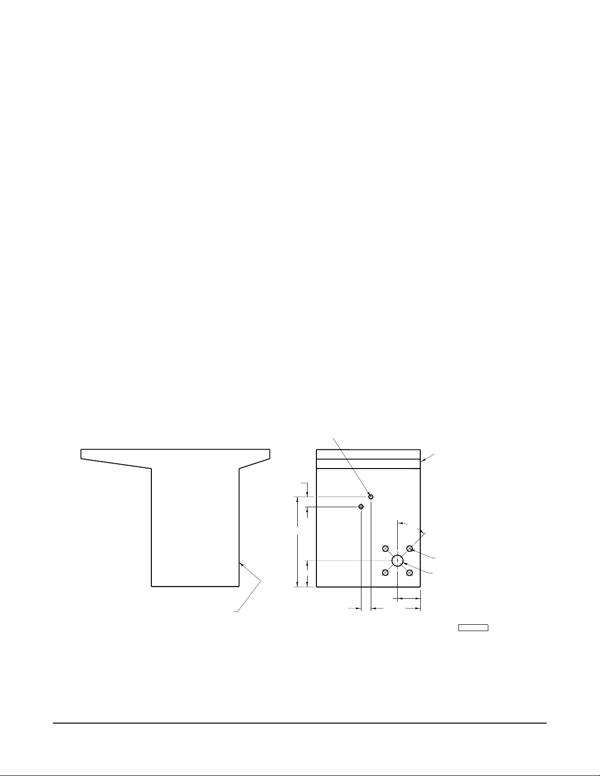
MODIFY THE DISHWASHER TANK (Fig's. 1-7)
Location of the SWS40 water supply system may not be the same on all models.
1. Drill two .625 diameter holes in the prewash tank for mounting the float switch box.
2. Drill four .750 diameter holes and one 2.25 diameter hole for mounting the pump.
.625 DIA.
(2 HOLES)
BACK SIDE OF
PREWASH TANK
2.000
45
5.000
11.000
TYP.
.750 DIA. 4 HOLES ON A
6.000 DIA. BOLT CIRCLE
2.250 DIA.
SWS-40 TO MOUNT
ON SIDE OF TANK
OPPOSITE PRE-WASH
PUMP
13.188
4.000
2.000
PL-52407
© HOBART CORPORATION, 1996
L-R SHOWN
R-L OPPOSITE
FT800 / FTM800
PRE-WASH TANK MODIFICATION
Fig. 1
– 2 –
BACK SIDE OF
PREWASH TANK
.625 DIA.
(2 HOLES)
2.000
2.000
13.875
5.000
4.000
45
TYP.
.750 DIA. 4 HOLES ON A
6.000 DIA. BOLT CIRCLE
2.250 DIA.
L-R SHOWN
R-L OPPOSITE
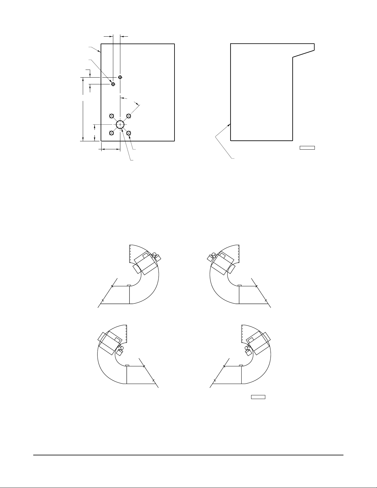
RS-22A / RS-36A
PRE-WASH TANK MODIFICATION
Fig. 2
PL-52410
SWS-40 TO MOUNT
ON SIDE OF TANK
OPPOSITE PRE-WASH
PUMP
CW-INCCW-IN
CW-OUT
CCW-OUT
PL-52438
RS-22 ON CURVE
SCRAP BASKET INSIDE OR OUTSIDE
CLOCKWISE OR COUNTERCLOCKWISE LAYOUT
(See Pages 4 & 5 for Individual Tank Modifications)
Fig. 3
– 3 –

.625 DIA.
(2 HOLES)
BACK SIDE OF
PREWASH TANK
2.000
SWS-40 FLOAT SWITCHES
TO MOUNT ON SIDE OF TANK
OPPOSITE PRE-WASH PUMP
.750 DIA. 4 HOLES ON A
6.000 DIA. BOLT CIRCLE
12.188
5.000
2.000
2.250 DIA.
4.000
RS-22 ON CURVE
TANK MODIFICATION
(CLOCKWISE - SCRAP BASKET INSIDE)
Fig. 4
BACK SIDE OF
PREWASH TANK
45
TYP.
4.000
.625 DIA.
(2 HOLES)
PL-52408
.750 DIA. 4 HOLES ON A
6.000 DIA. BOLT CIRCLE
2.250 DIA.
2.000
45
TYP.
4.000
4.000
12.188
5.000
2.000
RS-22 ON CURVE
TANK MODIFICATION
(CLOCKWISE - SCRAP BASKET OUTSIDE)
Fig. 5
– 4 –
PL-52412
SWS-40 FLOAT SWITCHES
TO MOUNT ON SIDE OF TANK
OPPOSITE PRE-WASH PUMP

.625 DIA.
(2 HOLES)
BACK SIDE OF
PREWASH TANK
2.000
12.188
2.250 DIA.
4.000
45
TYP.
SWS-40 FLOAT SWITCHES
TO MOUNT ON SIDE OF TANK
OPPOSITE PRE-WASH PUMP
(COUNTERCLOCKWISE - SCRAP BASKET OUTSIDE)
45
TYP.
5.000
2.000
RS-22 ON CURVE
TANK MODIFICATION
Fig. 6
BACK SIDE OF
PREWASH TANK
2.000
12.188
4.000
.750 DIA. 4 HOLES ON A
6.000 DIA. BOLT CIRCLE
PL-52409
.625 DIA.
(2 HOLES)
.750 DIA. 4 HOLES ON A
6.000 DIA. BOLT CIRCLE
2.250 DIA.
4.000
4.000
5.000
2.000
SWS-40 FLOAT SWITCHES
TO MOUNT ON SIDE OF TANK
OPPOSITE PRE-WASH PUMP
RS-22 ON CURVE
TANK MODIFICATION
(COUNTERCLOCKWISE - SCRAP BASKET INSIDE)
Fig. 7
– 5 –
PL-52413

MOUNT FLOAT SWITCH BOX AND FLOAT SWITCHES (Fig. 8)
Assemble Float to Switch
1. Hook float into the float retainer.
2. Slide float over barrel of switch and retainer, along with the retainer ring, until it snaps into the groove of the
probe and switch assembly. The float must be assembled to the bottom side of the probe.
3. Place the O-ring over the threaded end of the probe and switch assembly.
4. Insert the probe and switch assembly through the prewash tank and float switch box. Secure with washer,
lockwasher and hex nut.
5. Repeat the above procedures for the second float switch.
Mount Float Switch Box
Location of the SWS40 water supply system may not be the same on all models.
Slide lid and gasket assembly over the mounting studs. Secure with locknuts.
10-24 ELASTIC
STOP NUT
RETAINING
RING
PROBE &
SWITCH ASSY.
"O" RING
FLOAT
RETAINER
FLOAT
PL-52405
WASHER
LOCKWASHER
HEX NUT
Fig. 8
– 6 –

PUMP ASSEMBLY (Fig. 9)
The pump assembly and motor are already assembled.
1. Install the leg on the pump. Attach with four bolts, lockwashers and nuts supplied.
2. Screw the 2" nipple into the pump.
3. Screw the elbow into the 2" nipple.
4. Screw the 6" nipple into the elbow.
5. Screw the flange into the 6" nipple. When tightening the flange, the mounting holes must align with the drilled
holes in the prewash tank.
REAR OF TANK
(OPP.OF SUMP)
6" NIPPLE
FLANGE
2" NIPPLE
COMPANION
FLANGE
TYPICAL SWS40 PUMP MOUNTING
RS ON CURVE SHOWN
Fig. 9
GASKET
PL-52406
Mount Pump Assembly to the Prewash Tank
1. Install two gaskets, one to the inside and one to the outside of the prewash tank wall.
2. Install the flange (Fig. 9) to the gasket inside the tank.
3. Apply sealer between tank and gasket (both sides).
4. Bolt pump, gaskets and inside flange to the prewash tank, using four bolts, lockwashers and nuts supplied.
– 7 –

ELECTRICAL CONNECTIONS
WARNING: ELECTRICAL AND GROUNDING CONNECTIONS MUST COMPLY WITH THE APPLICABLE
PORTIONS OF THE NATIONAL ELECTRICAL CODE AND/OR OTHER LOCAL ELECTRICAL CODES.
WARNING: DISCONNECT ELECTRICAL POWER SUPPLY AND PLACE A TAG AT THE DISCONNECT
SWITCH INDICATING THAT YOU ARE WORKING ON THE CIRCUIT.
WARNING: REPLACE FUSE ONLY WITH SAME TYPE AND RATING.
Wire the switch assemblies and motor to the terminals provided in the wall-mounted control box or waterpress
tower, using the wire nuts provided. Refer to the electrical wiring diagram located in the control box for wiring
SWS40 option.
PLUMBING
WARNING: PLUMBING CONNECTIONS MUST COMPLY WITH APPLICABLE SANITARY, SAFETY, AND
PLUMBING CODES.
Install check valve, ball valve and piping (Fig. 10) between the dishwasher and pulper at the time of installation.
Use pipe sealant at every pipe joint.
1-1/2" NIPPLE
(BY OTHERS)
90 DEGREE
LONG RADIUS
ELBOW (TYP.)
(BY OTHERS)
SWS-40
PUMP
1-1/2" PIPING
(BY OTHERS)
1-1/2" CHECK VALVE
(SUPPLIED BY HOBART)
Fig. 10
TO
PULPER TANK
1-1/2" BALL VALVE
(SUPPLIED BY HOBART)
PL-52411
FORM 33716, Rev. A (11-96) PRINTED IN U.S.A.
– 8 –
 Loading...