


QE, EQE, QEH, & PEQ SERIES
N
S
T
R
U
C
T
I
O
N
S
I
ROLL-IN, ROLL-THROUGH
FOOD STORAGE CABINETS
AND PROOFERS
701 S. RIDGE AVENUE
TROY, OHIO 45374-0001
937 332-3000
www.hobartcorp.com
FORM 18529 Rev. E (Jan. 2000)
QE Series Roll-In Food Storage Cabinets
– 2 –
Installation, Operation, and Care of
PL-50949
DOOR
BOLT
SCREW
ASSEMBLY
MOUNTING
SCREW
HANDLE ASSEMBLY
KEY
MOUNTING SCREW
PLUG
BUTTON
QE, EQE, QEH, & PEQ SERIES
ROLL-IN FOOD STORAGE CABINETS & PROOFERS
SAVE THESE INSTRUCTIONS
GENERAL
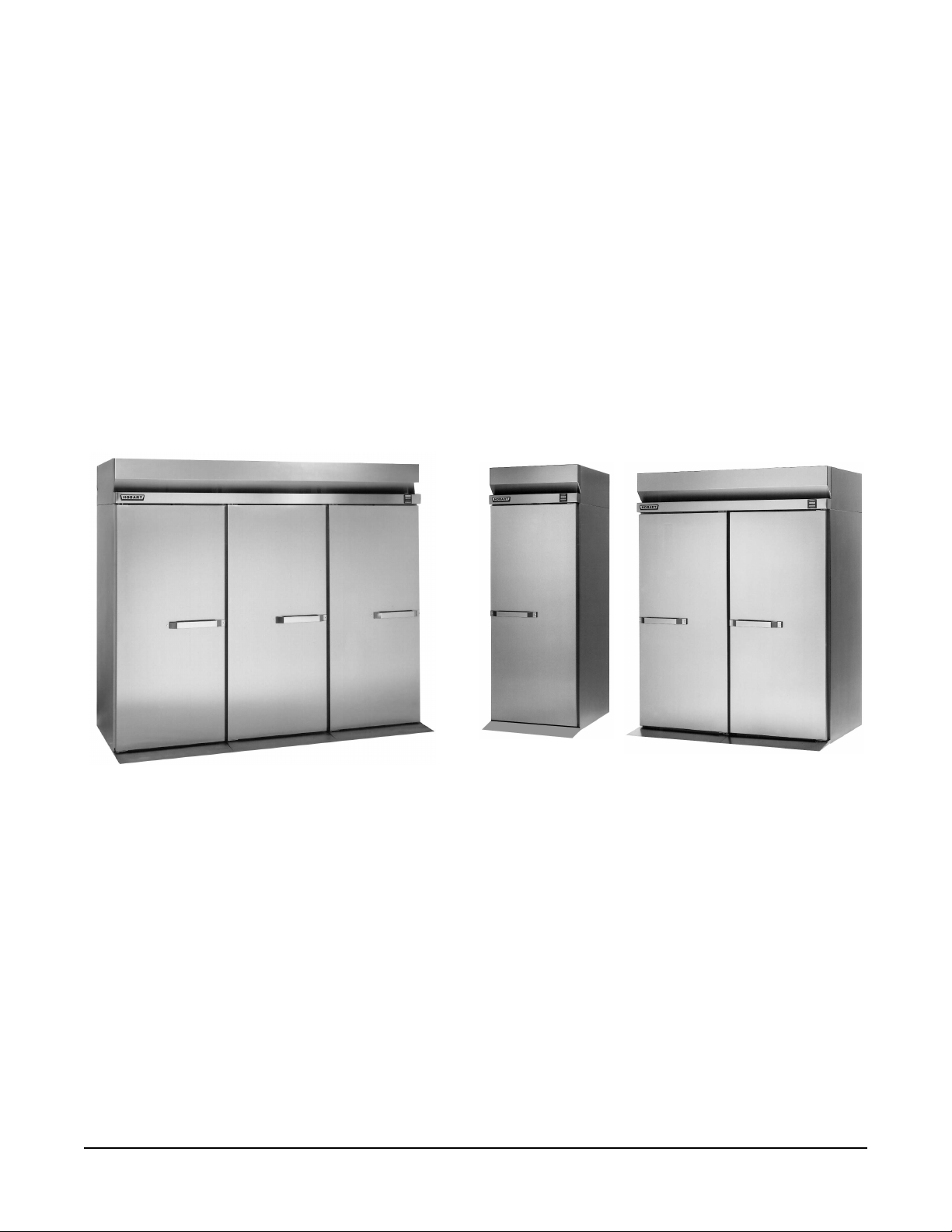
The QE and EQE Series Roll-in Food Storage Cabinets are available as medium temperature (38°F)
or frozen food (0°F) storage cabinets. The QEH Series is available as a hot food (180°F) storage
cabinet. QE, EQE, and QEH Series may be ordered as one-, two-, or three-section, roll-in or rollthrough cabinets. The PEQ Series may be ordered as one-, two-, or three -section roll-in or roll-through
proofer cabinets for the baking industry. Proofer cabinets control temperature, humidity, and time.
Thaw Proofer cabinets have a two-stage control, an initial Thaw stage is automatically followed by a
Proof stage; each stage independently controls temperature, humidity, and time.
INSTALLATION
UNPACKING
Immediately after unpacking, check for possible shipping damage. If the cabinet is found to be
damaged, save the packaging material and contact the carrier within 15 days of delivery.
Prior to installation, test the electrical service to verify that it agrees with the data plate located in the
upper left corner inside the cabinet.
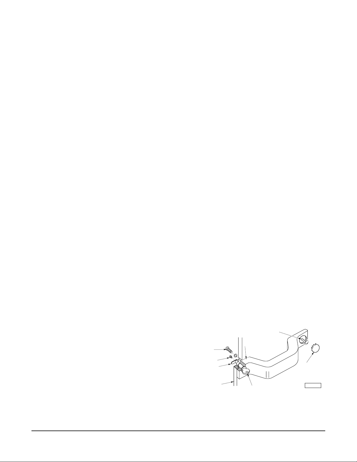
ASSEMBLY
Some components can be removed to allow the cabinet
to pass through short or narrow doorways.
The door handle can be removed, as follows:
1. Remove the screw and bolt from the tumbler.
2. Remove the two mounting screws and the handle
assembly (Fig. 1).
3. Replace in reverse order of disassembly.
NOTE: Proofers do not have locks.
Fig. 1
© HOBART CORPORATION, 1992
– 3 –
Door(s) and hinges can be removed, as follows:
PL-53452
UPPER
HINGE
SCREWS
(3)
LOWER
HINGE
SCREWS
(6)
NUT
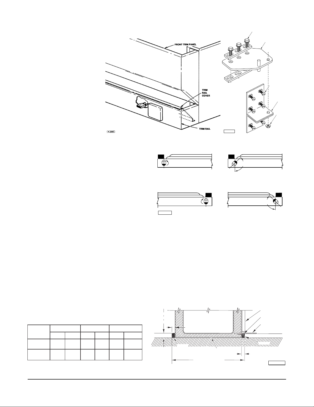
1. Lift up and remove the
front trim panel (Fig. 2).
2. Remove the screws
which secure the trim
rail cover (Fig. 2),
unplug the door switch
lead wires and remove
the screws which secure
the trim rail (Fig. 2).
Carefully lay the trim rail
on top of the cabinet —
avoid damaging or
kinking the thermometer
capillary tube.
3. Remove the three screws which secure the
upper hinge plate to the cabinet (Fig. 3).
This will remove hinge tension. Remove
the nut underneath the lower hinge plate
which secures the bottom hinge. Remove
door. Remove lower hinge plate (Fig. 3).
4. If the hinge mechanism should become
uncocked while changing the door, it will
be necessary to recock the hinge
mechanism. To do this, remove the door
from the cabinet and position the door face
5
down on a work table. Using a
/16" open
end or adjustable wrench, turn the hinge
mechanism shaft 135° (Fig. 4).
Fig. 2
Fig. 3
UNCOCKED POSITION
TURN 135º
– POSITION 1 – (LEFT-HAND HINGED DOOR)
UNCOCKED POSITION COCKED POSITION
TURN 135º
PL-50961
– POSITION 2 – (RIGHT-HAND HINGED DOOR)
POSITION DOOR IN ONE OF THE TWO POSITIONS SHOWN.
COCKED POSITION
135º
Fig. 4
135º
5. Replace the hinge plates and door(s) in the reverse order of disassembly.
If cabinets are too tall, the refrigeration system may need to be removed in order to pass through short
openings. Contact your dealer or authorized servicer if this becomes necessary.
Once the cabinet is in its final position, replace any components that may have been removed (door
handle, etc.) and then level the cabinet front-to-back and side-to-side using shims as required.
Before installing the ramp or flat threshold, seal between the bottom of the cabinet perimeter and the
floor by applying a bead of NSF-approved sealant, such as Dow Corning 732 or GE RTV108.
Cabinets equipped with flat threshold(s) must have a recessed floor (Fig. 5). The recessed floor should
3
/8" deep. This allows 1/4" for leveling shims.
be 1
tenibaC
epyT
tnorF
"73431/4""73761/2""730013/4"
gninepO
urhTssaP
733/4"431/4"733/4"761/2"733/4"0013/4"
noitceS-enOnoitceS-owTnoitceS-eerhT
htpeDhtdiWhtpeDhtdiWhtpeDhtdiW
snoisnemiDroolFdesseceR
CABINET
83-7/8"
APPROX.
– 4 –
1-3/8"
GROUT
1-1/2" (F.O.)
2-1/4" (P.T.)
1/4" SHIM
2-1/4"
RECESSED FLOOR
Fig. 5
FRONT
DOOR
HEATER
FLAT
THRESHOLD
FLOOR
GROUT
SUB-FLOOR
PL-53453

On pass thru models, the recessed floor dimension allows 21/4" clearance at both front and rear and
1
/2" on both sides. On a front opening cabinet, the recessed floor dimension allows 21/4" clearance at
the front, 1
1
/2" clearance at the rear, and 1/2" on both sides (Fig. 5). The plug for the heater under the
flat threshold must be connected to the receptacle, provided, before installing grout.
The space between the cabinet base and the recessed opening must be filled with grout for sanitary
purposes. DO NOT fill the area below or above the hinge plate with grout, as the fastener on the bottom
of the hinge plate must remain accessible to remove the door for service. Place a piece of cardboard
around the hinge plate to make sure this area is free of any grout. Keep grout away from heater plug.
Ramp (Equipped as an Alternate to Flat Threshold)
Install ramp(s) and ramp heater(s) as follows:
The heater is secured to the bottom of the ramp
(Fig. 6). Connect the heater plug into the receptacle
provided at the bottom of the door opening (Fig. 6).
Position the ramp by placing the lip of the ramp
inside the door opening. Hook the ramp on the clips
provided at the bottom of the door opening (Fig. 6).
Ramp heaters are not used on QEH or PEQ models.
Fig. 6
Shelves (Fig. 7)
The shelves and shelf clips are provided only if specially
PILASTER
ordered. Insert shelf clips in pilaster slots and install the shelves.
Index holes are provided in the pilaster to help in leveling the
shelves.
COLD AIR
DUCT
Bonus shelves are provided to fill the space between the
standard shelves. These are positioned and supported by the
standard shelves.
NOTE: Loosen all thumb screws which secure shelf pilasters
BONUS
SHELF
INDEX
HOLE
SHELF
CLIP
SHELF
and light cover(s) prior to placing product in cabinet. Thumb
screws should be loose enough to remove with your fingers so
parts can be readily removed for cleaning without the use of
tools. Failure to comply with this request will invalidate the NSF
PL-50910
listing.
Fig. 7
Miscellaneous
Some models have the compressor specially mounted to help prevent damage during shipment. If the
compressor is mounted on shipping blocks, they must be removed prior to operation. If the compressor
is mounted on springs, refer to the tag attached to the compressor.
On cabinets with remote refrigeration systems, place the condensate dish heater in the condensate
dish and connect it to the outlet provided.
– 5 –
PLUMBING CONNECTIONS (PEQ Series Proofer only)
WARNING: PLUMBING CONNECTIONS MUST COMPLY WITH APPLICABLE SANITARY, SAFETY,
AND PLUMBING CODES.
Make sure the water supply has proper hardness and pH. The recommended water hardness range
is 4 – 6 grains per gallon. The recommended pH range is 6.5 to 8.0. Consult your local water company
and/or water conditioner dealer before installing a PEQ Series Proofer.
ELECTRICAL CONNECTIONS (Cord-Connected Roll-Ins) 120 Volts / 60 Hertz / 1 Phase Only
WARNING: THIS MACHINE IS PROVIDED WITH A THREE-PRONG GROUNDING PLUG. THE
OUTLET TO WHICH THIS PLUG IS CONNECTED MUST BE PROPERLY GROUNDED. IF THE
RECEPTACLE IS NOT THE PROPER GROUNDING TYPE, CONTACT AN ELECTRICIAN.
ELECTRICAL CONNECTIONS (Permanently Connected Roll-Ins)
WARNING: ELECTRICAL AND GROUNDING CONNECTIONS MUST COMPLY WITH APPLICABLE
PORTIONS OF THE NATIONAL ELECTRICAL CODE AND/OR OTHER LOCAL ELECTRICAL
CODES.
WARNING: DISCONNECT THE ELECTRICAL POWER SUPPLY AND PLACE A TAG AT THE
DISCONNECT SWITCH TO INDICATE THAT YOU ARE WORKING ON THE CIRCUIT.
Refer to the wiring diagram supplied with the cabinet.
PRESTART CHECKS (Refrigeration Cabinets Only)
REFRIGERANT LINES — Check for tubing shifts due to shipping that would cause operating noise,
wear, or leaks.
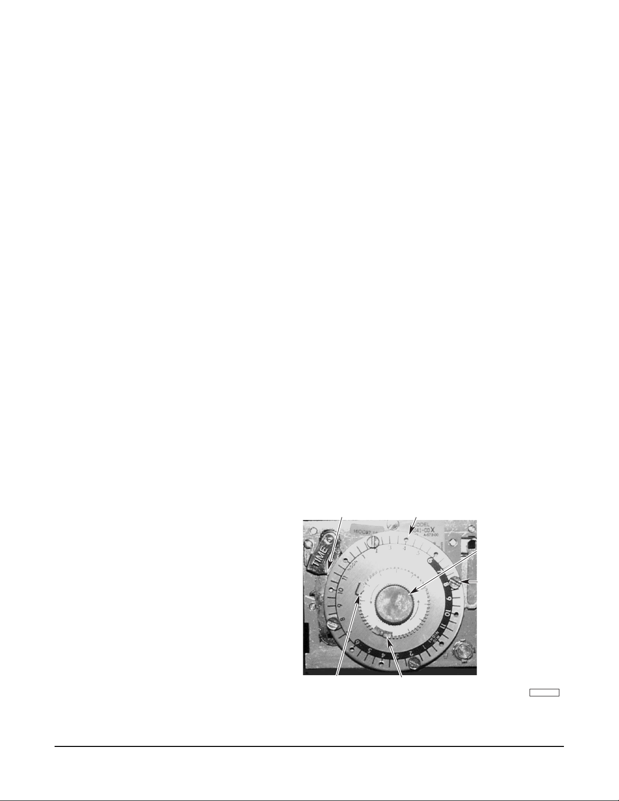
DEFROST TIMER (Low Temperature Units and Convertible Models in Low Temperature Mode) —
When power is initially applied to the cabinet, the exterior dial of the defrost time clock (Fig. 5) must
be set to the correct time of day.
To access the defrost timer, remove the front
TIME-OF-DAY POINTER
EXTERIOR DIAL (24 HOUR)
trim panel (Fig. 4) by lifting up and out. Open
door on the defrost timer box. Turn the inside
knob counterclockwise until the exterior dial is
TURN KNOB
COUNTERCLOCKWISE
positioned so the correct time of day is at the
time of day pointer. Replace the front trim
DEFROST CYCLE PINS
panel when done.
The defrost timer (Fig. 5) is set at the factory
for four 26-minute defrost cycles per day (2
AM, 2 PM, and 8 PM). Depending on local
8
AM,
conditions, it may be necessary to change the
frequency or duration of defrost cycles.
END DEFROST
(26 MINUTES)
If the power supply is interrupted, the defrost
timer must be reset to the correct time of day.
BEGIN DEFROST
PL-41397-1
Fig. 8
– 6 –
OPERATION
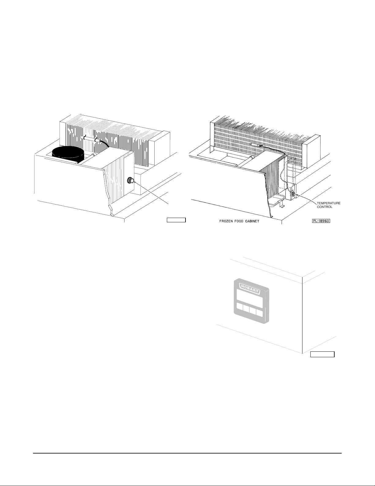
CONTROLS (Refrigeration)
TEMPERATURE CONTROL — The temperature control is set at the factory, but local conditions may
necessitate slight adjustment. To adjust the temperature control, lift up and remove the front trim panel (see
Fig. 2) and turn the control knob (Fig. 9 or 10) a small amount at a time. Turning the control knob in the direction
of the arrow lowers the temperature. The control knob has a marked "OFF" position which interrupts power to
the compressor and condenser fan only, not the entire roll-in.
TEMPERATURE
CONTROL
ONE SECTION REFRIGERATOR CABINET
PL-50544
Fig. 9 Fig. 10
STANDARD THERMOMETER (Fig. 11) — The standard
digital thermometer is calibrated at the factory and does
not permit recalibration.
OPTIONAL DIAL THERMOMETER — The optional dial
thermometer can be recalibrated. Compare the cabinet
thermometer with an accurate test thermometer. If there is
any variation, contact a Hobart-authorized Refrigeration
Service Company.
OPERATIONAL CHECK — The refrigeration and defrost
cycles should be checked for proper operation and the
thermometer(s) should also be checked for correct
temperature indication — before product is stored in the
cabinet.
Refrigerator
PL-50767
Fig. 11
– 7 –
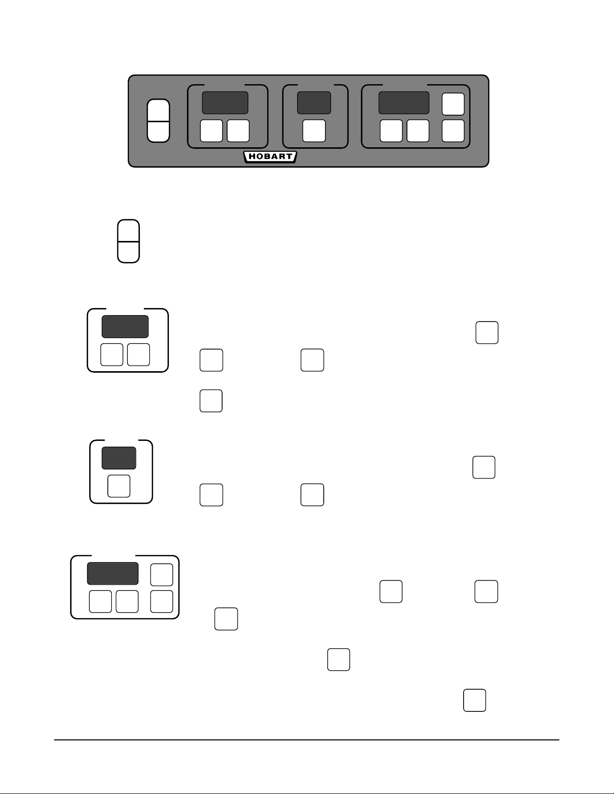
CONTROLS — Proofer and Thaw Proofer (Figs. 12 & 13)
T
ON
OFF
TEMP
SET VIEW
• F
HUM
%
SET
•
TIMER
SET
START
▲
▼
Proof Box
Fig. 12
On-Off Switch Turns the Proofer Control On or Off. The On-Off switch is not a
ON
disconnect switch —
TO SERVICE THE CABINET.
ALWAYS DISCONNECT POWER AT THE SOURCE
OFF
TEMP
SET
• F
VIEW
TEMP normally displays the Set-Point Temperature.
To adjust the Set-Point Temperature, press and hold
to Increase or
▲
to Decrease.
▼
while using
SET
•
TIMER
SET
HUM
SET
START
%
▲
▼
displays the Actual Temperature.
VIEW
HUM displays the Humidity Set-Point.
To adjust the Humidity Set-Point, press and hold
to Increase or
▲
to Decrease.
▼
while using
SET
TIMER displays the minutes remaining [zero (0) indicates not in use].
To s et the Time, press and hold
or
To start the Timer, press
to Decrease.
▼
. The Time (minutes) displays and begins
STA R
while using
SET
to Increase
▲
flashing as it counts down. When the Timer reaches zero (0), a beeper
sounds for 30 seconds. To stop the beeper, press
– 8 –
SET
.

CONTROLS — Thaw Proofer (Fig. 13)
T
T
SET THA W
•
PROOF
•
AUTOMATIC
•
MODE
ON
OFF
TEMP
SET VIEW
Press
MODE
• F
and
HUM TIMER
%
SET
Fig. 13
or
▲
▼
The mode lights indicate control function
SET THA W
PROOF
•
AUTOMATIC
MANUAL PROOF mode allows you to set Temperature, Humidity, and
Time values for manual or automatic proofing operations. To start
a manual (non-timed) proofing operation, press
Proofer values, refer to page 8.
SET THA W
•
PROOF
AUTOMATIC
ET THAW mode allows you to set Temperature, Humidity, and Time
S
values for the Preheat and Thaw portions of an Automatic cycle
without disturbing an ongoing proofing operation. Thaw values are
set the same as Proofer values — refer to page 8. Control returns
to manual Proof mode if no buttons are pressed in 30 seconds. To
enter Set Thaw mode, the timer must not be running.
SET THA W
•
PROOF
•
AUTOMATIC
•
MODE
•
START
SET
▲
▼
Thaw Proofer
to select Proof, Set Thaw, or Automatic mode.
:
. To set
STAR
UTOMATIC PREHEAT — displays Thaw Temperature and Thaw
SET THA W
PROOF
•
AUTOM ATIC
A
Humidity. Thaw Temperature flashes when reached, indicating
ready-to-load. Load the product and press
to begin an
STAR
Automatic Thaw and Proof cycle.
UTOMATIC THAW — maintains the Thaw Temperature and Thaw
SET THA W
•
PROOF
•
AUTOMATIC
SET THA W
PROOF
•
•
AUTOM ATIC
A
Humidity while the Thaw Time counts down. After the Timer counts
down to zero, the control immediately goes into Automatic Proof.
AUTOMATIC PROOF — maintains the Proof Temperature and Proof
Humidity while the Proof Time counts down. After the Timer counts
down to zero, the control beeps and the display flashes indicating
that the product is ready to be unloaded from the proofer and moved
to an oven for baking. The control returns to manual Proof mode.
During Automatic mode —
To cancel the Thaw portion of an Automatic cycle, press Timer Set and advance to the Proof portion.
To cancel the entire Automatic Thaw and Proof cycle, press the Mode button and return to manual Proof.
– 9 –
REMOTE CONTROL — Proofer and Thaw Proofer (When Equipped)
SET
TEMP
SET
HUM
SET
TIMER
▼
Connect Remote Control
'Phone Jack' to Terminal
on Electrical Box on Top
VIEW
TEMP
MODE
START
TIMER
▼
of Unit
Fig. 14
The Remote Control is used in conjunction with either Proofer Controls or Thaw Proofer Controls described on
pages 8 – 9. The
MODE
key is used only on Thaw Proofer models.
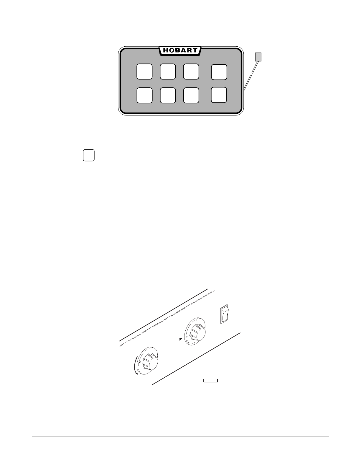
CONTROLS — Hot Food Storage Cabinets (Fig. 15)
The ON-OFF switch controls power to the fan motors and the thermostat / heater circuit. Turn the switch OFF
whenever the cabinet is not in use. The ON-OFF switch is not a disconnect switch — ALWAYS DISCONNECT
POWER AT THE SOURCE TO SERVICE THE CABINET. The temperature control dial, which has a marked OFF
position (no heat), is used to select the temperature at which the food will be held. When this dial is OFF, the
air circulating fans continue to run.
The HUMIDITY control dial is used to regulate the humidity level inside the cabinet. Three-section cabinets have
two HUMIDITY control dials.
ON
TEMPERATURE
F
F
HI
LO
HUMIDITY
O
0
0
1
1
0
2
OFF
PL-53471
Fig. 15
– 10 –

MAINTENANCE
CLEANING
Cabinet
Clean the inside of the cabinet and the doors weekly with a warm water solution of mild household liquid
dishwashing detergent (such as Palmolive green or Ivory). Do not use anything containing grit,
abrasive materials, bleach or harsh chemicals. Be cautious with new or improved formulas; use only
after being well tested. Rinse thoroughly and dry with a clean soft cloth. Do not use steel wool to clean
surfaces.
NOTE: Failure to follow use, care and maintenance instructions may void your Hobart warranty.
Gaskets
Door gaskets should be cleaned weekly using a warm water solution of mild household liquid
dishwashing detergent (such as Palmolive green or Ivory). Never allow gaskets to contact concentrated
cleaners or disinfectants. This can cause premature failure of the gasket material.
Condenser Coil
WARNING: DISCONNECT ELECTRICAL POWER SUPPLY BEFORE CLEANING THE CONDENSING UNIT.
Check the condenser coil weekly. This surface must be kept free of dirt and grease for proper system
operation. Remove the front trim panel and carefully vacuum or brush dirt and lint from the condenser
coil. Replace the trim panel.
Evaporator Coil, Drain Pan, Condensate Loop, and Condensate Dish
When needed, flush these components with fresh water. This should be a part of any routine
maintenance program and can prolong the life of the equipment.
Light Bulb Replacement
Replace light bulb(s) with 40 watt incandescent appliance type bulb(s) ONLY. The protective cover
can easily be removed and replaced.
For additional information or to discuss a maintenance program, contact your local authorized
refrigeration servicer.
– 11 –

— NOTES —
FORM 18529 Rev. E (Jan. 2000) PRINTED IN U.S.A.
– 12 –
 Loading...