

Page 1
SCB Super
Char Broiler with piezo ignition.
INSTALLATION OPERATION
This appliance shall be installed in conformity with the current regulations and
only used in a well-ventilated location. Consult these instructions before
installing and using this appliance.
PLE200513 – C 08-07 EU8079
PLEASE KEEP THIS MANUAL IN A SAFE PLACE FOR FUTURE REFERENCE.
CONTENTS.
Page 2

SECTION PAGE
SAFETY AND GENERAL INFORMATION
Safety information 1 3
Safety guidelines 1.1 3
Warning symbols 1.2 4
Liability 1.3 4
Definitions 1.4 5
Environmental responsibility 1.5 5
Packing material 1.5.1 5
Disposal of your old appliance 1.5.2 5
Foreword 2 5
General information 3 5
SCB Super Char Broiler component identification. Photograph 1. 6
Features and benefits 3.1 7
Safety instructions 4 7
Never 4.1 7
Always 4.2 8
INFORMATION FOR OPERATORS AND USERS
Operating the SCB Super Char Broiler 5 9
Lighting instructions-piezo ignition 5.1 9
Using the SCB Super Char Broiler 5.2 10
Reversing the grates 5.3 11
Using the grate removal tool 5.4 12
Cleaning 6 12
Cleaning the grates 6.1 12
Cleaning the radiants 6.2 12
Cleaning external surfaces 6.3 12
INFORMATION FOR INSTALLATION AND COMMISSIONING.
Design and construction data 7 13
Technical information. Part 1. Table 1 13
Technical information. Part 2. Table 2 15
Burner and pilot orifice dimensions. Table 3. 15
Gas categories and pressures. Table 4. 16
Gas consumption and energy usage Table 5. 16
Installation dimensions. Figure 1. 17
Installing the SCB Super Char Broiler 8 17
Unpacking and handling 8.1 17
Location 8.2 18
General installation guidelines 8.3 18
Mounting of the appliance 8.4 19
Gas pipe work 8.5 19
Ventilation 8.6 20
Gas installation 8.7 21
Fitting the gas regulator 8.8 21
Electrical earth bonding 8.9 21
Gas burner securing tape removal 8.10 22
1
Page 3

Commissioning 9 22
Check the manifold gas pressures 9.1 22
Operator training 9.2 23
INFORMATION FOR MAINTENANACE AND REGULAR
SERVICING
Maintenance 10 23
Gas control system component identification. Photograph 15. 23
Cleaning the burner baffle 10.1 24
Adjusting the pilot burner flame 10.2 24
Replacing the pilot burner 10.3 25
Replacing the thermocouple 10.4 26
Replacing the main burner 10.5 26
Replacing the burner nozzle 10.6 27
Replacing the gas control valve 10.7 28
Fault finding 11 29
Fault summary 11.1 29
Servicing 12 30
Service interval Table 6 31
Recommended spare parts 13 32
Service contacts 14 33
2
Page 4

1.0 SAFETY INFORMATION.
The procedures and precautions contained in this manual apply to SCB Super Char
Broiler only when used in the prescribed manner.
If the SCB Char Broiler is used other than in the recommended manner, the operator
will be responsible for his/her own safety and for the safety of the other persons who
may be involved.
The information in this manual has been prepared to assist the operator to
understand, maintain, and operate the Char Broiler. In order to prevent accidents,
read, understand and follow all the precautions and warnings contained in this
manual before installation or operating for the first time. This manual must be studied
to obtain a clear understanding of the SCB Super Char Broiler and its capabilities.
Hot surfaces and gas are dangerous and may cause injury if sufficient precautions
are not taken prior to operating or servicing the SCB Super Char Broiler.
The SCB Super Char Broiler must only be serviced by Qualified Service
Personnel. Ensure the gas supply has been isolated and all hot surfaces are
allowed to cool to an acceptable temperature before attempting to service the unit. In
certain fault finding situations it may be necessary to operate the machine whilst still
hot; in which case extreme caution must be used.
These instructions are only valid for the countries listed in table 4 section 8.
This appliance shall be installed by a competent, trained and qualified person in
conformity with the current local gas regulations. The appliance must only be used in
a well-ventilated location. Consult the instructions before installing and using this
appliance.
The SCB Super Char Broiler is only intended for professional use by qualified
people.
1.1 SAFETY GUIDELINES.
Ensure sufficient precautions are observed during manually handling of the SCB
Super Char Broiler particularly when moving into position on installation. Reference
must be made to manual handling regulations. The SCB Super Char Broiler weights
are given in table 2, section 8. Refer to section 5 for installation and operating safety
instructions.
• Do not hose or pressure clean this appliance. It is vital to adhere to the
cleaning instructions detailed in this manual.
• Do not remove any covers or loosen any fittings whilst the appliance is
operating.
• Ensure this manual is kept in an easily accessible place near the SCB Super
Char Broiler for future reference.
3
Page 5

• All operators must be trained in the safe use and operation of the appliance.
• This appliance is not intended for use by persons if their physical, sensory or
mental capabilities prevent them from using it safely.
• This SCB Super Char Broiler is not intended for use by children.
• Ensure the gas supply has been isolated before attempting to service or move
the appliance.
• The appliance must be disconnected from the gas supply before withdrawing.
• Instructions must be placed in a prominent position within the kitchen that will
advise operators of this equipment of the procedure in the event a gas leak is
detected by smell or other means.
• Hot surfaces and gas are potentially hazardous and may cause injury if
sufficient precautions are not taken prior to operating or servicing the
machine.
• Always have your gas appliance regularly serviced; at least once a year,
depending on frequency of use (refer to table 6, section 12). For information
on service contracts please contact your local Hobart sales office.
• Prior to connecting the appliance check the gas type and rating on the data
plate corresponds with the gas supply.
• The area around the SCB Super Char Broiler must always be kept free and
clear of combustibles such as solvents, cleaning fluids, mops, rags, brooms,
etc.
• Do not obstruct any vents or openings on the appliance.
1.2 WARNING SYMBOLS.
To identify the safety messages in this manual, the following symbol has been used
The "Warning" symbol is found primarily where the corresponding
information is important for the safe use of the machinery.
1.3 LIABILITY.
Installations and repairs which are not carried out by Authorised technicians or the
use of other than original spare parts, and any technical alterations to the
appliance, may affect the warranty set out in the standard conditions of sale.
4
Page 6

1.4 DEFINITIONS.
Qualified operators. The SCB Super Char Broiler is only intended for professional
use by qualified operators. Qualified operators are those personnel who have
received training in the operation of the appliance from a suitable qualified person
and have carefully read the information in this manual and are familiar with the
equipment’s function or had previous experience with the operation of this SCB
Super Char Broiler.
Qualified installation personnel. Any ‘work’ performed within the UK on the
appliance including installation that is within the scope of the Gas Safety (Installation
and Use) Regulations shall be carried out by a business that is CORGI approved
(Council for Registered Gas Installers) and approved by the Health and Safety
Executive (HSE). For countries outside the UK qualified installation personnel must
be experienced and familiar with precautions required, have complied with all
requirements of state and local authorities having jurisdiction. In the EU installation
must comply with national or local requirements of the country of destination of the
appliance.
Qualified Service Personnel: Those who are familiar with Wolf equipment,
competent, trained and approved by Hobart UK. All service personnel are required to
be equipped with a complete set of manuals and original service parts.
1.5 ENVIRONMENTAL RESPONSIBILITY.
1.5.1 PACKING MATERIAL.
The pallet and protective polyethylene packing film have been selected
from materials that are environmentally friendly for disposal or can
normally be recycled. Instead of throwing them away, please ensure they
are recycled.
1.5.2 DISPOSAL OF YOUR OLD APPLIANCE.
Old appliances contain materials that can be recycled. Please contact your local
waste collection centre; scrap merchant or local Hobart office about potential
recycling schemes.
2.0 FOREWORD.
Hobart reserves the right to alter the design of their products without prior notice.
Whilst every effort is made to ensure this publication reflects the latest design, the
Company cannot guarantee full compliance.
Take pride in your SCB series Char Broiler - keep it clean and in good mechanical
condition. Refer to the cleaning and maintenance sections in this manual.
3.0 GENERAL INFORMATION
The information and instructions contained in this manual may not cover all details or
variations in the equipment, nor provide for every eventuality to arise with
5
Page 7
installation, operation, or maintenance. If additional information is required please
contact your local Hobart office.
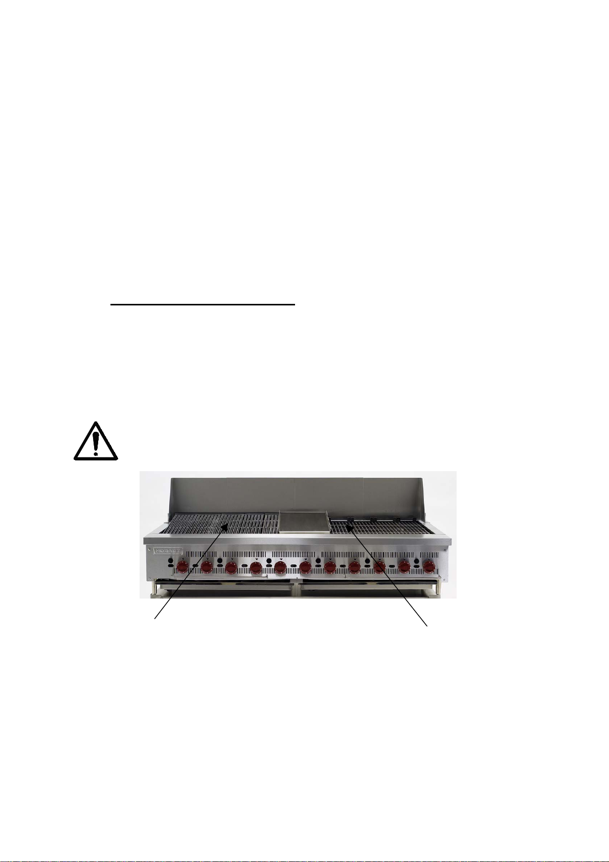
The SCB series Char Broiler is a commercial gas cooker intended for the cooking of
meat, seafood, pita bread and stockpot heating. The SCB features ‘flame arrestor’
broiling grates that control fat flare-up and ensure uniform broiling temperatures. The
specially designed cast iron grates have an angled grease trough to ensure all food
waste and fat runs off to enable the equipment to operate at its optimum
performance. The grates are removable to allow the radiants to be quickly and easily
cleaned. The broiling grates are reversible so they can be either flat or angled
depending on the food product being cooked. Steel baffles positioned under each
burner reflect heat up to the radiants and ensure the grease drawer and drip pan
area remains at a relatively lower temperature. The finned heat radiants situated
under the grates control cross draughts within the SCB Char Broiler to maintain a
constant cooking temperature for maximum efficiency and optimum cooking results.
The piezo ignition system enables the appliance to be lit without removing the grates
and radiants. The piezo igniter lights the pilot burner. One piezo igniter is used for
two pilot burners.
The SCB Char Broiler is supplied with adjustable stainless steel legs for bench
mounting
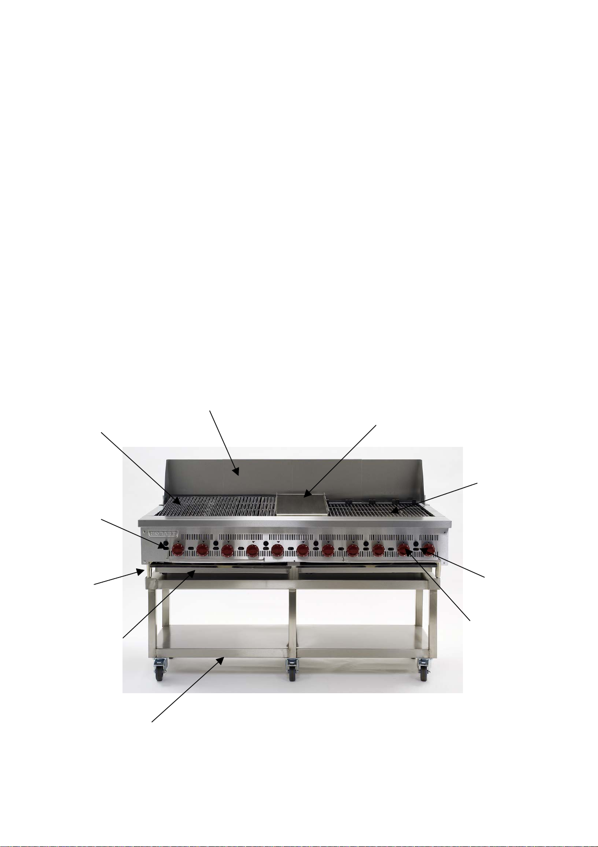
REVERSIBLE
BROILING
GRATES
(ANGLED).
PILOT
BURNER
VIEWING
WINDOW
100 mm
HIGH
LEGS
SLIDING
DRIP TRAY.
SPLASH
BACK
FRY
PLATE
REVERSIBLE
BROILING
GRATES
(FLAT).
PIEZO
IGNITER
GAS
CONTROL
KNOB
MOBILE
STAND
SCB SUPER CHAR BROILER COMPONENT
IDENTIFICATION. PHOTOGRAPH 1.
6
Page 8
3.1 FEATURES AND BENEFITS.
• Robust and strong design.
• Reversible grates flat or angled.
• Cast iron radiants to provide an even cooking temperature over the entire grate.
• Heat deflector to ensure improved cooking efficiency and create a lower
temperature zone in the drip tray area.
• Flame failure protection.
• Removable front grease channel for easy cleaning.
• Full or half flame burner control.
• Finned heat radiants to control cross draughts within the Char broiler and
maintain a constant cooking temperature.
• Effective guard to protect the pilot burner from food debris.
• Removable grates and radiants to ensure daily cleaning in quick and easy.
• Slanted cast iron grates with fat gully.
• High power burners each rated at 4.2 kW.
• Straight cast iron grates available.
• Stainless steel drip trays to collect fat and food waste.
• Individually controlled burners.
• Piezo ignition of pilot burners.
• Easy clean stainless steel exterior surfaces.
• Tap stem guard
• Insulated side and rear panels.
• Optional stainless steel fry plate for fish, eggs, bacon etc.
• Optional splash-back 100mm and 250 mm high easily removed for cleaning.
• Optional grate removal tool.
• Mobile or static stand options available.
4.0 SAFETY INSTRUCTIONS.
ONLY A FULLY TRAINED AND COMPETENT PERSON MUST USE THE
SCB SUPER CHAR BROILER
The following instructions must be observed when using the appliance.
Note: The SCB Super Char Broiler must only be used for the purpose it was design
and inline with the supplied operating instructions.
GRILL.
4.1 NEVER
• Allow children, infirm persons or unqualified personnel to operate the grill.
• Operate the SCB Super Char Broiler if a fault develops or is unsafe.
• Wear loose clothing.
• Wear flammable clothing such as silks, polyester, etc that are highly flammable
when using this appliance.
• Use bleach, hypochlorite or chlorine compounds to clean the SCB Super Char
Broiler internally or externally.
7
Page 9

• Use excessive force when operating which could affect the stability of the
appliance.
• Operate the SCB Super Char Broiler if parts are disassembled.
• Use the appliance in an unsafe condition.
• Clean the SCB Super Char Broiler with scouring powder or a scouring pad.
• Dry tea towels and cloths on the appliance.
• Obstruct openings or heat vents
• Tamper or change any sealed devices on the appliance.
• Use wax tapers to ignite the pilot light.
• Allow debris to accumulate on the grates.
4.2 ALWAYS
• Use the appliance in a well-lit area.
• Use the SCB Super Char Broiler as intended and inline with the operating
instructions.
• Be aware of hot surfaces on the appliance.
• Wear safety glasses whilst cooking.
• Apply cooking oil to the grates before use.
8
Page 10
5.0 OPERATING THE SCB SUPER CHAR BROILER.
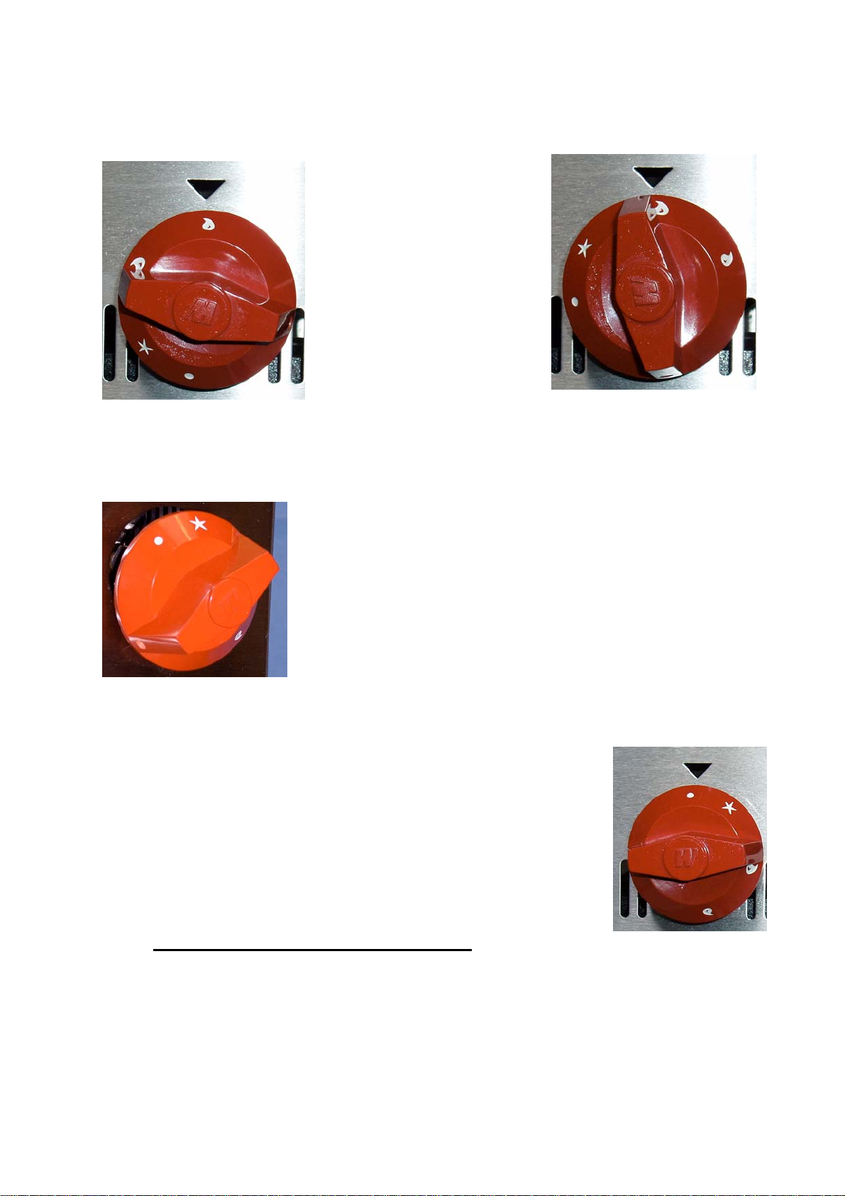
5.1 LIGHTING INSTRUCTIONS –PIEZO IGNITION.
It is not necessary to remove the grates and radiants when using the piezo ignition
system. However in certain instances the grates and radiants may be removed.
WARNING! Before attempting to remove the grate and radiants ensure
they are at an acceptable temperature to touch and handle. This will
normally take approximately 3 hours after turning off the main burner.
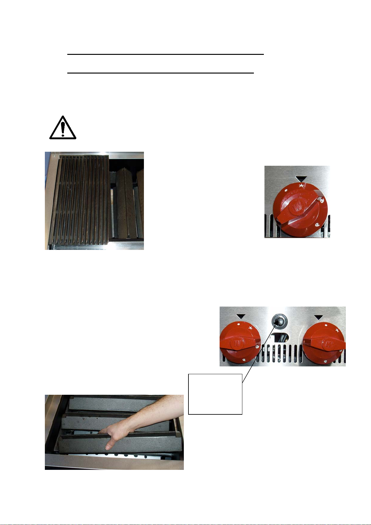
1. Ensure the gas supply to the SCB is turned
‘on’.
2. Push in and turn the
control knob approximately 30
degrees anti-clockwise to the
ignition point indicated by the
star (*) symbol as shown in
photograph 3.
IGNITION POSITION PILOT
GRATES AND RADIANTS.
PHOTOGRAPH 2.
3. Push and hold the control knob in for approximately 5 seconds to release gas
from the pilot burner jet and then press the piezo igniter. Normally only 2 or 3
‘clicks’ are required to ignite each pilot burner.
Hold the control knob in for 10 to 15 seconds
before releasing. This allows the flame failure
control system to heat up to its normal
operating temperature. If the pilot burner does
not remain illuminated wait three minutes and
try again. This ignition position (*) allows the
pilot light to burn continuously. In a cold kitchen
the heat up time may be longer, up to
20 seconds.
Piezo igniter
positioned
between 2
gas valves.
4. If the grates and radiants have
been removed replace them but only
with the pilot jet illuminated. Place the
radiant on the backrest first and then
lower the front.
5. To ignite the main burner, turn the
LIGHT ‘ON’ POSITION.
PHOTOGRAPH 3.
PIEZO IGNITER POSITION
BETWEEN GAS VALVES.
PHOTOGRAPH 4.
REPLACING THE RADIANTS.
PHOTOGRAPH 5.
knob to the ‘flame’ position. Allow
9
Page 11
approximately 30 minutes for the appliance to heat up to temperature before starting
to cook.
MAIN BURNER ‘ON’
HALF FLAME POSITION.
PHOTOGRAPH 6.
6. To extinguish the main burner and leave the pilot flame
burning turn the control knob clockwise to the star position
shown in photograph 8.
PILOT BURNER
‘ON’ POSITION.
PHOTOGRAPH 8.
7. To turn off the SCB char broiler main burner and pilot flame, rotate the control
knob to the 'OFF' position indicated by the white dot.
MAIN BURNER ‘ON’
FULL FLAME POSITION.
PHOTOGRAPH 7.
‘OFF’ POSITION.
PHOTOGRAPH 9.
5.2 USING THE SCB CHAR BROILER.
The following notes provide general guidance on the operation of the SCB Char
Broiler.
• Apply cooking oil to the grates before use. Excess grease will run forward and
drip onto the front grease trough.
10
Page 12
• When the SCB Char Broiler is loaded with food product adjust the gas valves to a
lower setting to prevent overheating causing the food to char.
• The grates must be scraped with a wire brush to keep them clean. Do not allow
debris to accumulate on the grates.
• Adjust the flame to the low setting or pilot burner during slack periods to conserve
energy.
• The SCB Char Broiler is a free venting appliance. All the products of combustion
and heat generated during cooking pass through the grates. When food product
is placed on the grates the ventilation is partially blocked causing a temperature
build-up. The appliance will operate more efficiently in these circumstances with
the gas valves adjusted down one third to one half.
5.3 REVERSING THE GRATES.
The slope of the grates can be altered to suit the type of product being cooked. The
shape of the casting at the far end allows the grates to be positioned either with a
slope to the front trough of the appliance or flat, as shown below. The angled
position is used for the cooking of meat and fish products where any oil or fat must
run into the trough situated at the front of the appliance. The flat position enables
pans to be heated on the top of the unit.
WARNING! Before attempting to alter the grate positions ensure they are
at an acceptable temperature to touch and handle. This will normally take
approximately 3 hours after turning off the main burner.
ANGLED
GRATES
GRATES SHOWN FLAT AND
SLOPING. PHOTOGRAPH 10.
FLAT
GRATES
11
Page 13

5.4 USING THE GRATE REMOVAL TOOL (OPTIONAL).
The following sequence describes the procedure to remove or reverse a grate.
4
12
5
7 8
3
6
9
12
10
Caution! Wear suitable protective clothing when handling hot grates.
11
12
Page 14
6.0 CLEANING.
DO NOT HOSE OR PRESSURE CLEAN THIS SCB CHAR BROILER.
INDIVIDUAL PARTS MAY BE PRESSURE CLEANED. REFER TO THE
FOLLOWING SECTION.
DO NOT USE ANY ABRASIVE CLEANERS
REFER TO THE RELEVANT COSHH DATA SHEETS PRIOR TO USING ANY
CLEANING PRODUCTS.
WEAR APPROPRIATE PERSONAL PROTECTIVE EQUIPMENT.
Prior to cleaning the appliance extinguish the main and pilot burner flames, isolate
the gas supply using the locally fitted isolating valve and ensure the appliance is at
an acceptable temperature to handle prior to cleaning.
6.1 CLEANING THE GRATES.
WARNING! Before attempting to remove the grates ensure they are at an
acceptable temperature to touch. This will normally take approximately 3
hours after using with the main burner.
1. Scrape the grease trough cast into the grates so the grease flows uninhibited
into the gutter and drawer. This will reduce the risk of flare-up.
2. The grates may be laid in the flat position and the burners then turned on full
to burn off excessive fat and carbon. When the grates have cooled off, clean
thoroughly with a wire brush.
3. The grates may be immersed in a strong commercial non-toxic cleaning
solution over night. In the morning flush with hot water and steam clean to
remove any debris.
4. To clean the front gutter, remove the grates and lift out the gutter. Wash
thoroughly with a hot detergent solution.
6.2 CLEANING THE RADIANTS.
Occasionally the cast iron radiant situated under the grates may require cleaning.
WARNING! Before attempting to remove the grates and radiants ensure
they are at an acceptable temperature to touch. This will normally take
approximately 3 hours after using with the main burner.
1. The radiants may be cleaned thoroughly using a wire brush or by immersing
in a strong commercial non-toxic cleaning solution over night. In the morning
flush with hot water and steam clean to remove any debris.
6.3 CLEANING THE EXTERIOR SURFACES.
When the appliance is cool, the gas control knobs and stainless steel surfaces may
be cleaned with a mild soap and water solution applied with a damp cloth. Rinse
the surface with clean water and dry with a soft cloth. Do not use an abrasive or
strong liquid cleaner on the stainless surface since they may damage the finish.
Page 15
CAUTION ABOUT USING "SPRAY-ON" CLEANERS
Be careful when using spray cleaners. Read the safety data sheet prior to use and
follow the instruction label on the container. Wear appropriate protective clothing.
Some cleaners may contain caustics.
7.0 DESIGN AND CONSTRUCTION DATA.
The data listed in table 1 applies to all of the natural gas and LPG versions of the
SCB Super Char Broiler.
TABLE 1. TECHNICAL INFORMATION, PART 1.
Parameter Units Model
#
SCBXXCE-1
#
SCBXXCE-2
Type of gas Natural (G20) LPG (G31)
Appliance category I
2H
I
3P
Nominal heat input per burner kW (Btu/hour) 4.2 (14,300) 4.2 (14,300)
Gas supply pressure
m bar 20 37
(nominal)
Gas supply pressure
m bar 17 30
(minimum)
Gas supply pressure
m bar 25 45
(maximum)
Gas operating pressure
(standard orifice)
m bar (inches
water gauge)
12.5 (5) 25.0 (10)
Pressure tap nozzle size mm (inch) 9.0 (0.354) 9.0 (0.354)
Minimum gas supply pipe
mm (inch) 22 (7/8) 22 (7/8)
internal diameter
Burner orifice diameter (no
mm 1.70 1.10
adjustment)
Burner orifice identification #051 #057
Pilot orifice diameter mm 0.533 0.356
Pilot orifice identification 1.8N 1.0P
Thermocouple hold on time
Seconds 15 15
(nominal)
Flame out time (nominal) Seconds 30 30
Type of appliance A A
Recommended hood air flow
m/s 0.4 0.4
velocity
Minimum clearance dimensions
Combustible material, rear,
mm (inch) 305 (12) 305 (12)
above grid level
Combustible material, rear,
mm (inch) 75 (3) 76 (3)
below grid level
Combustible, material sides,
mm (inch) 225 (9) 225 (9)
above grid level
Combustible, material sides,
mm (inch) 75 (3) 75 (3)
below grid level
13
Page 16

Parameter Units Model
#
SCBXXCE-1
#
SCBXXCE-2
Combustible, material below mm (inch) 100 (4) 100 (4)
Non combustible, material
mm (inch) 150 (6) 150 (6)
below
Non combustible material,
mm (inch) 75 (3) 75 (3)
rear, above and below grid
level
Non combustible material,
mm (inch) 0 (0) 0 (0)
sides, above and below grid
level
Adjustable leg thread size 3/8” UNC 3/8” UNC
Gas connection (to BS2779) BSP G3/4A (3/4”
parallel male
G3/4A (3/4” parallel
male thread).
thread).
Initial heat up time on
Minutes 30 30
maximum burner setting
Time for grates and radiants
Hours 3 3
to cool to a safe handling
temperature.
Grate weight each kg 6.3 6.3
Radiant weight each kg 5.1 5.1
Noise level dB (A)
Storage conditions.
Temperature and humidity.
o
C,
% RH
##
less than 60
+5 to +55,
85
##
less than 60
+5 to +55,
85
#
Refer to table 2 for specific model data.
##
In accordance with EN-ISO 11202.
14
Page 17

TABLE 2. TECHNICAL INFORMATION, PART 2.
Parameter Units SCB25CE SCB36CE SCB47CE SCB60CE SCB72CE
Net weight kg 86.5 127 169.5 211 260
External
dimensions
Shipping
weight
Shipping
dimensions
(including
pallet)
Number of
burners
Total burner
rating
Nominal gas
consumption
(natural gas)
Nominal gas
consumption
(LPG)
Typical rate of
ventilation
based on
54m3/minute
per m2 of
appliance.
W x D x H
mm
kg 107 152 196 251.5 308
W x D x H
mm
kW
(Btu/hour)
m3/h 1.78 2.67 3.56 4.90 5.79
m3/h 0.69 1.03 1.37 1.89 2.23
m3/minute2840526780
635 x 810
x 380
745 x 920
x 500
4681113
16.8
(57200)
914 x 810
x 380
1025 x
920 x 500
25.2
(85800)
1194 x
810 x 380
1305 x
920 x 500
33.6
(114400)
1524 x
810 x 380
1635 x
920 x 560
46.2
(157300)
1829 x
810 x 380
1940 x
920 x 560
54.6
(185900)
TABLE 3. BURNER AND PILOT ORIFICE SIZES.
Gas P mbar Jet description Size
G20 20 12.5 Burner Orifice 1.70 mm (0.067”)
Pilot Orifice 1 off 0.533 mm
(0.021”)
G31 29 25 Burner Orifice 1.10 mm (0.043”)
G31 37 25 Pilot Orifice 1 off 0.22 mm (1 off
0.0087”)
G31 50 25
15
Page 18
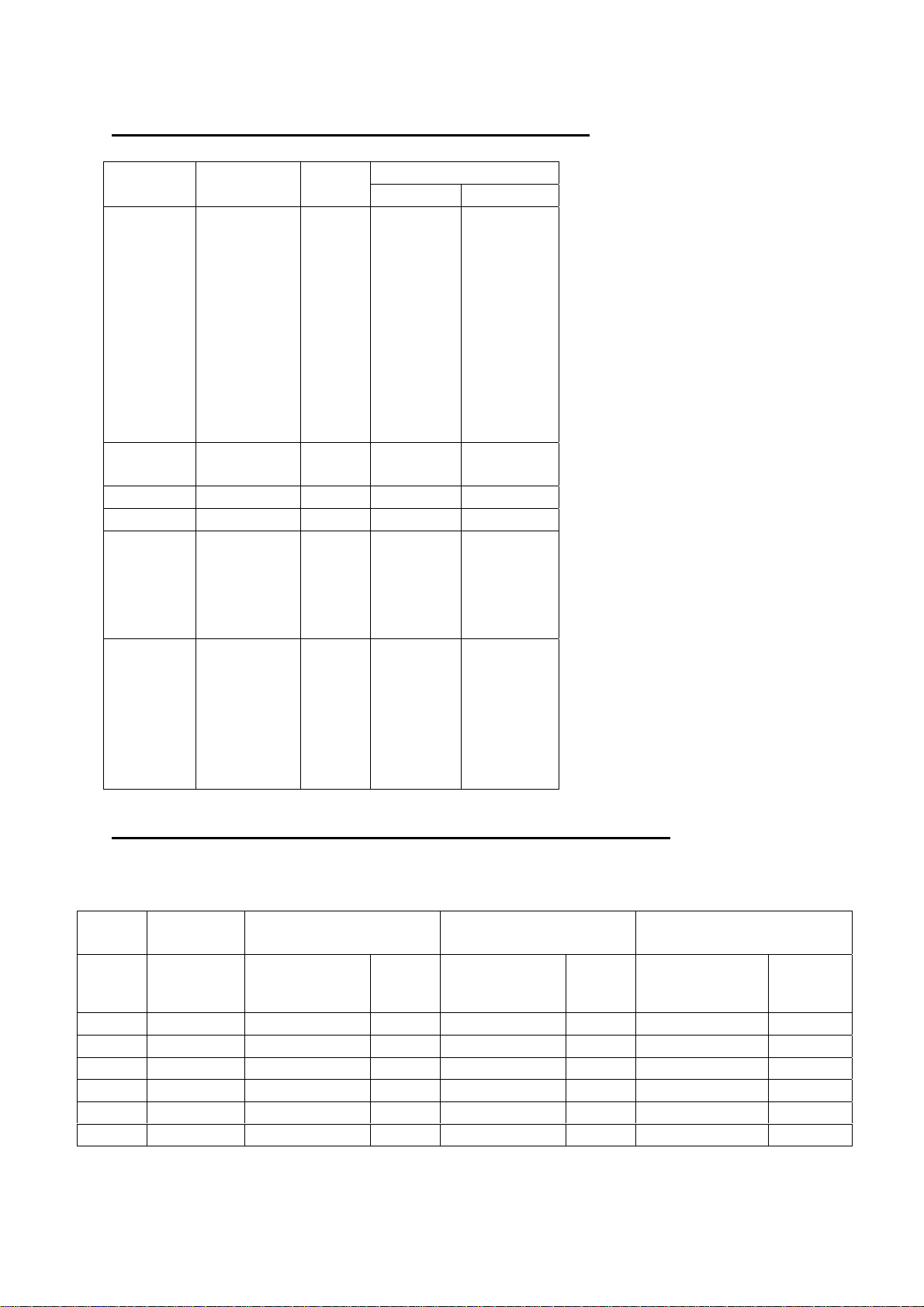
TABLE 4. GAS CATEGORY AND PRESSURES.
P mbarCountry Category Gas
Inlet Manifold
AT I2H G20 20 12.5
DK
IE
PT
ES
IT
SE
FI
GR
CH
GB
DE I2E G20 20 12.5
LU
FR I2Er G20 20 12.5
NL I3P G31 30 25
FR I3P G31 37 25
GB
BE
IE
GR
NL I3P G31 50 25
GB
BE
ES
DE
GR
FR
TABLE 5. GAS CONSUMPTION AND ENERGY USAGE.
The following table is based on actual test results.
Pilot burner Half flame main
burner
Model Number of
burners
SCB25 4.00 0.06 0.68 0.54 5.83 1.65 17.86
SCB36 6.00 0.09 1.02 0.81 8.75 2.47 26.79
SCB47 8.00 0.13 1.36 1.08 11.67 3.29 35.72
SCB60 11.00 0.17 1.88 1.48 16.04 4.53 49.12
SCB72 13.00 0.20 2.22 1.75 18.96 5.35 58.05
Gas
consumption
M3/hr kWh M3/hr kWh M3/hr kWh
Energy
usage
Gas
consumption
16
Energy
usage
Full flame main burner
Gas
consumption
Energy
usage
Page 19
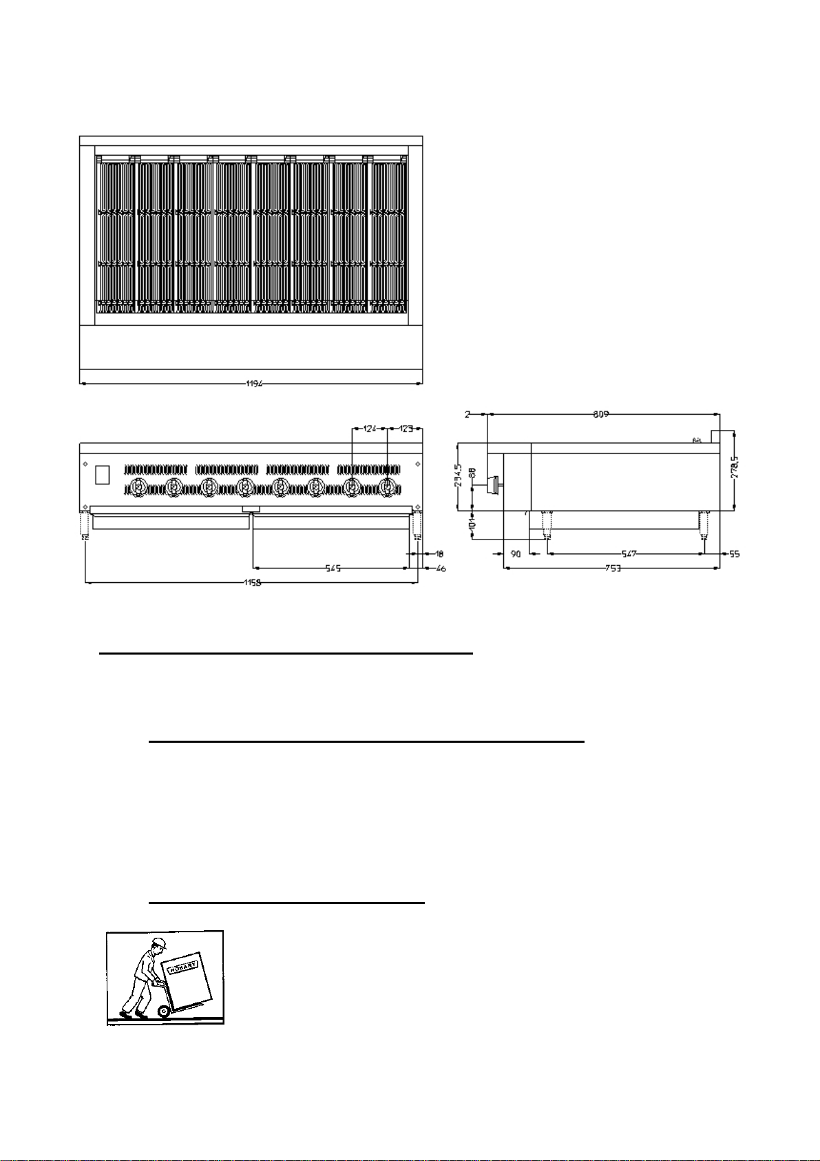
FIGURE 1. INSTALLATION DIMENSIONS (example is for an
SCB47CE refer to table 2 for all models).
8.0 INSTALLING THE SCB SUPER CHAR BROILER.
In order to ensure a safe and satisfactory installation it is important that discussions
take place between those involved with the kitchen design, selection of the grill,
layout and installation of the equipment. The SCB must be installed by a competent
person to ensure safe and hygienic operation. Consideration must be given to
catering and food hygiene.
8.1 UNPACKING AND HANDLING.
Wherever possible the appliance should be transported to the
installation position in the packaging provided to avoid damage.
Do not use a sharp knife to cut into the packaging as damage to
the machine may occur. Check for possible shipping damage. If
the unit is found to be damaged, save the packaging material
and contact your nearest Hobart sales office.
17
Page 20

Caution: The SCB Char Broiler is a heavy object and must be correctly
handled and lifted to avoid personal injury. Refer to table 2 for weights and
dimensions. For UK installations refer to the ‘Manual Handling Operations
Regulations 1992 and HSE guidance notes for manual handling.
With the appliance in the vicinity of its final position remove the shrink wrap film and
lift the unit from the transportation pallet.
Care must be taken during this operation to ensure: -
a) All required safety measures are taken to ensure correct lifting and handling to
avoid risk of injury through dropping, falling and tilting.
b) No damage occurs to the machine, that could impair the normal operation.
8.2 LOCATION.
The SCB Char Broiler is not suitable for outdoor installation and must not be installed
where a water jet could be used for cleaning. The appliance must only be operated
by trained staff and must be installed in an area where the use and maintenance is
restricted to trained personnel.
This appliance shall be installed in conformity with the current regulations (BS6173)
and used only in a well-ventilated location. Consult the instructions before installing
and using this appliance.
The LPG version of the SCB must not be installed in a room having no means of low
level natural ventilation direct to outside (for example in a basement or cellar).
Important! Ensure there is sufficient space around the SCB to enable safe
operation. Servicing may be more difficult because of reduced clearances and you
should always check that equipment specifications permit the close proximity of
other equipment. Refer to table 1 for minimum clearances. Service access is
required to the front, bottom, sides and top of the appliance. It is suggested that at
least 600 mm of free area be provided to the front of the unit.
8.3 GENERAL INSTALLATION GUIDELINES.
The SCB Char broiler should not be located adjacent to customer services where hot
surfaces may cause burns.
The SCB Char Broiler must not be installed next to open burners or fryers. Other
types of gas fired appliances can be positioned adjacent to the SCB Char Broiler
however there must not be any obstruction to the front.
Before proceeding with the installation, remove the protective plastic film from all
panels. Use an appropriate cleaning product to remove any adhesive residues from
the stainless steel.
18
Page 21
When installing never enclose the unit’s lower area in any way that would obstruct
the flow of air into the appliance.
Crevices need to be avoided between and behind the appliance, and pipe work
where any spillage may lodge.
All supports shelves and wall finishes must be capable of withstanding a minimum
temperature of 65°C and be non-combustible.
The SCB must be secured in position to prevent any movement. Restraints must not
be fixed to the gas supply pipes or points not sufficiently anchored.
For any ‘work’ performed in the UK on the appliance including installation that is
within the scope of the Gas Safety (Installation and Use) Regulations shall be carried
out by a business that is CORGI approved (Council for Registered Gas Installers)
and approved by the Health and Safety Executive (HSE).
The SCB Char Broiler shall have a single manual isolating valve to be used when
servicing or cleaning.
A manual operation valve must be fitted to the gas supply to the catering area to
enable it to be isolated in an emergency. Ideally this valve should be located outside
the catering area or near an exit in a readily accessible position.
On completion of the installation a leak test must be performed. CAUTION!
A naked flame must not be used for this purpose. Leak test solutions may
cause corrosion therefore thorough rinsing with water is required after
testing.
8.4 MOUNTING OF THE APPLIANCE.
The SCB Char Broiler must be mounted on a flat surface. The appliance is supplied
with 4 off legs 100 mm high (4”) to ease cleaning underneath. This appliance is not
suitable for building in to other appliances.
Select a suitable flat level surface that can support the weight of the SCB Char
Broiler and food product (refer to table 2 for weights and dimensions). The unit must
be installed on a horizontal flat surface. Once the appliance is in position adjust the
feet to ensure the unit is level to within 1mm in 1 metre side to side and front to back.
The SCB Char Broiler must be adequately secured and restrained in position.
8.5 GAS PIPE WORK.
The installation of the gas pipe work in the UK must be in accordance with latest
revision of standard BS6173.
• Gas pipe work must be installed in a sound and workman-like manner and be
constructed of materials suitable for its purpose.
• Pipes conveying gas must be adequately identified.
19
Page 22

• For rigidly fixed pipe work a union or similar method of disconnection must be
provided between the isolation valve and appliance.
• The clearance between the gas pipe and wall must be at least 25mm to ease
cleaning.
• Semi-rigid pipe must conform to BS7838 and only be installed in a ventilated area
where it cannot be damaged.
• If a flexible connection is installed it must not touch the floor or be exposed to
excessive heat.
• The gas outlet to which the connection is made must be located in the same
room as the appliance.
• If a flexible connection is used it must not be concealed within or routed through
any wall or partition.
• Flexible gas connections must not come into contact with sharp edges or wiring.
8.6 VENTILLATION.
Provision is required for adequate dispersal of combustion and cooking fume
products, supply of combustion air and ventilation for the appliance and cooking
processes. Adequate fresh air is required in kitchens to provide air for combustion to
limit the effects of heat and humidity (reference must be made to HVCA DW/171 to
ensure there is adequate ventilation for the appliance). Refer to table 2 for the typical
ventilation rate. Consideration must be made for other gas appliance that may be in
the same area as the SCB Char Broiler.
This type ‘A’ appliance is not designed to be connected to a flue or other device for
evacuating the combustion products to the outside of the room where it is installed.
The appliance must be installed in a suitably ventilated room in accordance with
current regulations (BS6173).
It is advisable that a hood is fitted above the appliance to ensure effective extraction
of combustion fumes and cooking odours. The plan dimension of the canopy should
exceed the plan area of the SCB Char Broiler by an overhang of 250mm at the front
and 150mm at the ends. The hood and ductwork must be constructed from noncombustible material. Table 2 specifies the ventilation airflow requirement.
For new installations the gas supply to the appliance must be interlocked with any
mechanical ventilation system fitted to ensure safe operation of the appliance.
The SCB must not be installed in a catering area where the ventilation system could
adversely affect its safe operation.
Broiling produces greasy cooking odours and vapours that require filtration. The
filters must be reviewed frequently and cleaned on a regular basis (at least every
month).
The SCB Char Broiler must be supported on a suitably designed surface that will
withstand the weight of the appliance and food product. The appliance must be
restrained to prevent any movement during use.
20
Page 23
Low level ventilation is always required for appliances using a gas (LPG) heavier
than air.
It is strongly recommended that a flammable gas and CO detector is fitted that is
suitable for catering environments.
8.7 GAS INSTALLATION.
When installed in the United Kingdom the installation must conform to
the Gas Safety (Installation and Use) Regulations. This appliance must
be earthed as shown in section 9.9.
It is strongly recommended that a flexible connection be used for the gas supply to
the appliance.
Refer to table 2 and the appliance data plate to ensure there is an adequate supply
of gas. Check that the gas type and gas pressure is consistent with the gas supply of
the SCB. If the appliance is not suitable for the gas being supplied it shall not be
installed or connected to the gas supply.
Conversion of the appliance from one gas to another must be carried out strictly in
accordance with Hobart instruction’s by a competent person.
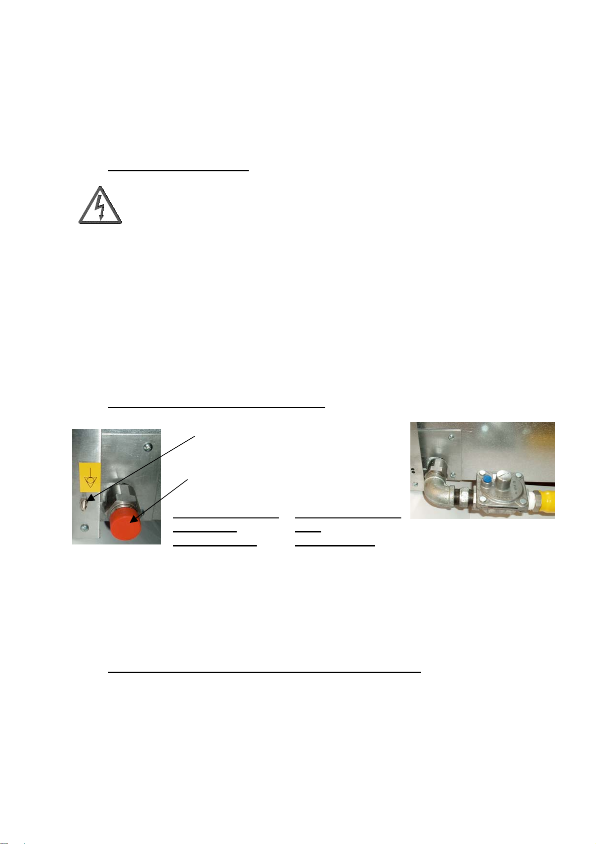
8.8 FITTING THE GAS REGULATOR.
Earth bonding
screw.
Gas inlet
connection.
PHOTOGRAPH 11.
GAS INLET
CONNECTION.
The gas regulator is supplied loose with the appliance. Fit the regulator as follows:
1. The SCB Char Broiler gas inlet pipe connection is ¾” BSP male. Apply
suitably approved jointing compound to the threads.
2. Using a spanner tighten the gas regulator on to the appliance. Note the
direction of gas flow arrow.
PHOTOGRAPH 12.
GAS
REGULATOR.
8.9 ELECTRICAL EARTH BONDING CONNECTION.
Where necessary for electrical safety the SCB Char Broiler should be fitted with an
earth bonding screw as shown in photograph 11. Check the earth bonding resistance
is less than 0.1Ω.
21
Page 24
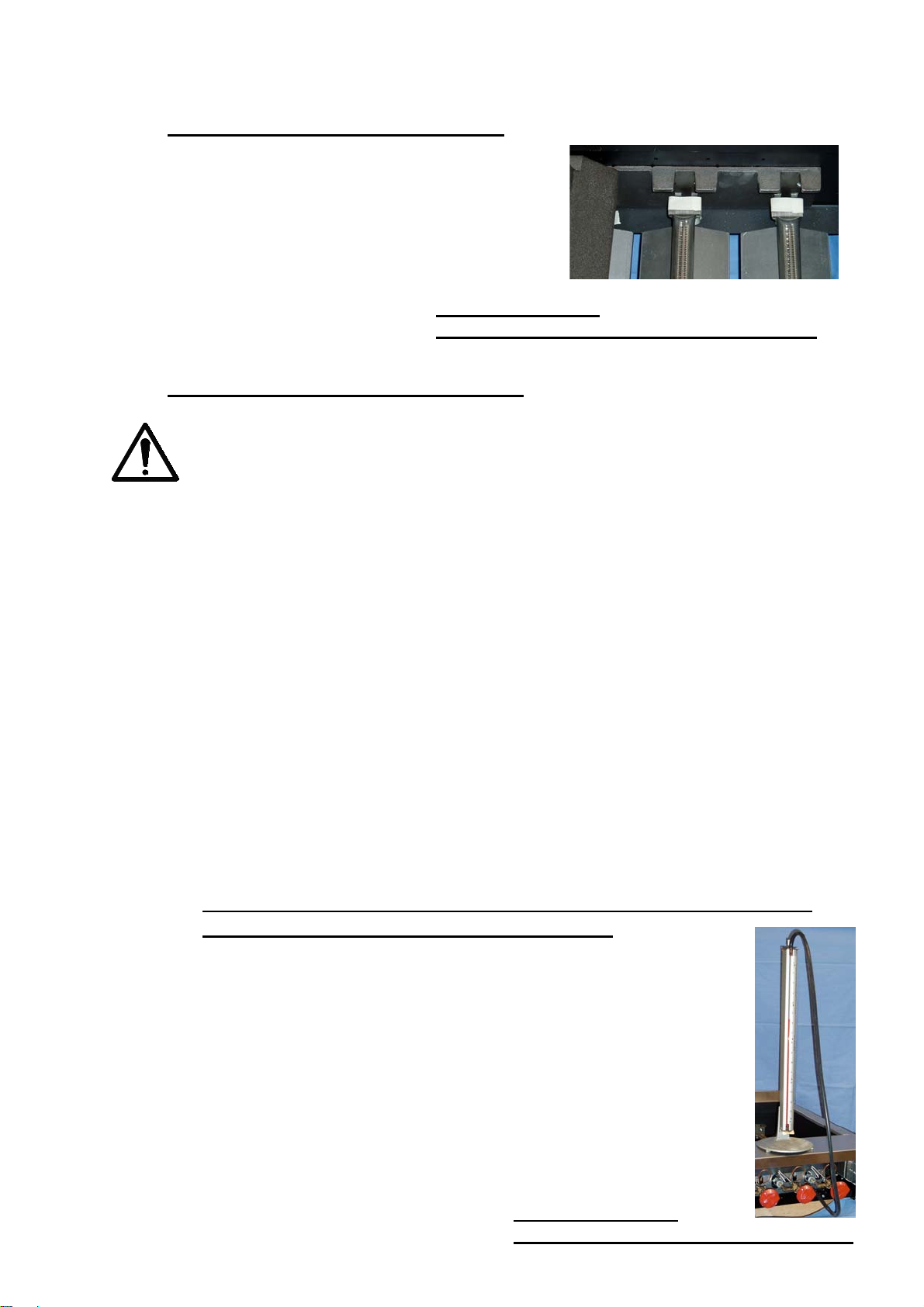
8.10 GAS BURNER SECURING TAPE.
The gas burners are secured in place during transit
with masking tape as shown in photograph 13.
Carefully lift off the grates and radiants as detailed in
section 6.1 and remove the masking tape before use.
PHOTOGRAPH 13.
GAS BURNER SECURING MASKING TAPE.
9.0 COMMISSIONING INSTRUCTIONS.
This SCB Char Broiler is only intended for professional use by suitably
trained people. Ensure operators have read and understood this manual
and have received adequate training.
The installation of the appliance must be commissioned by a competent person
using the following instructions. In the UK the installation must be in accordance with
BS6173.
All new gas pipes upstream of the appliance must be tested for soundness and
purged of air before igniting the pilot burners. This can take several minutes
depending on the length of gas pipe to the appliance gas regulator. Hold several gas
burners in the priming position and allow the gas to flow through the pipe work.
Commissioning shall check the correct operation of the flame failure valve,
thermocouple and the burner pressure is adjusted to the value given in the technical
information table 1 and on the data plate.
All pipe work between the isolating valve and SCB Char Broiler must be tested for
leaks with no perceptible drop in water pressure gauge over a period of two minutes
at a pressure at least the operating pressure and not more than 1.5 times the
operating pressure. Following pressure testing the pipe work must be purged of air.
9.1 TO CHECK THE MANIFOLD GAS INLET PRESSURE
(DOWNSTREAM OF THE REGULATOR).
1. The gas inlet pressure to the appliance must be checked using a 0.80 m
bar WG manometer with an accuracy of at least 0.1 m bar WG.
2. Remove the screw from the 9mm-diameter pressure test nipple. The
pressure test nipple is situated on the front of the appliance (see
photograph 15).
3. Connect a silicone rubber tube to the manometer and test nipple. Ignite
the pilot and main burner and check the operating inlet pressure. Refer
to table 1 for the correct pressure.
4. Adjust the gas regulator to achieve the required pressure if necessary.
5. Replace the screw into the pressure test nipple and check for soundness
with a gas leak detector solution.
22
PHOTOGRAPH 14.
GAS INLET PRESSURE MANOMETER.
Page 25
9. 2 OPERATOR TRAINING.
Take time to explain the correct operation and cleaning of the SCB Char Broiler to
the users referring to this manual. Leave this manual with the operator and explain
that it is important to use it for further reference.
10.0. MAINTENANCE.
The frequency of service maintenance will depend on customer usage. Refer to table
5, section 13 for recommended service intervals.
The SCB Char Broiler must not be modified other than as specified by Hobart UK. A
competent person shall carry out all servicing and maintenance work.
If the appliance restraints are disconnected in order to remove it for servicing a
notice must be fixed near the restraint reminding the operator to reconnect the
restraint and any electrical earth bonding.
1. All moving parts must be checked for wear and lubricated, if necessary.
Replace if excessively worn.
2. The burner ports and throats should be thoroughly cleaned. The burner
orifice must be free from grease and lint. When cleaning DO NOT insert a
pick in the burner porthole.
3. SCB Char Broilers equipped with appliance restraints should be checked by a
competent person to ensure proper installation.
4. All places where oil, grease, or food can accumulate must be kept clean at all
times.
5. Pilot lights are to be kept clean and adjusted to the correct flame height to
assure constant ignition and to prevent fire flash-outs caused by delayed
ignition.
6. At the first sign of sticking all valves and controls, should be lubricated by a
trained person using high temperature grease.
7. At the slightest odour of gas, all fittings, pipes, tubing and controls should be
tested with a gas leak detector solution.
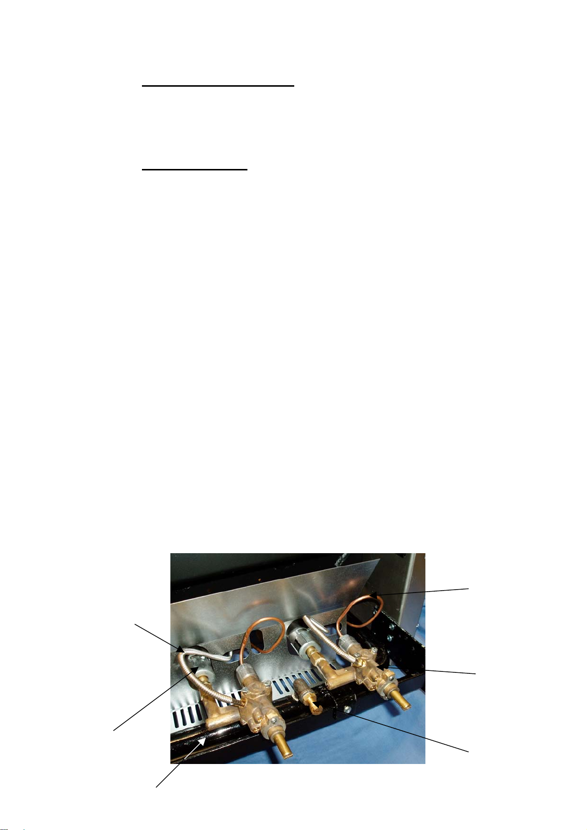
Pilot valve
gas supply
pipe.
Main
gas
burner
Gas supply
manifold.
23
Thermo
couple
Gas
control
valve.
Gas test
nipple
GAS CONTROL SYSTEM COMPONENT
IDENTIFICATION. PHOTOGRAPH 15.
Page 26
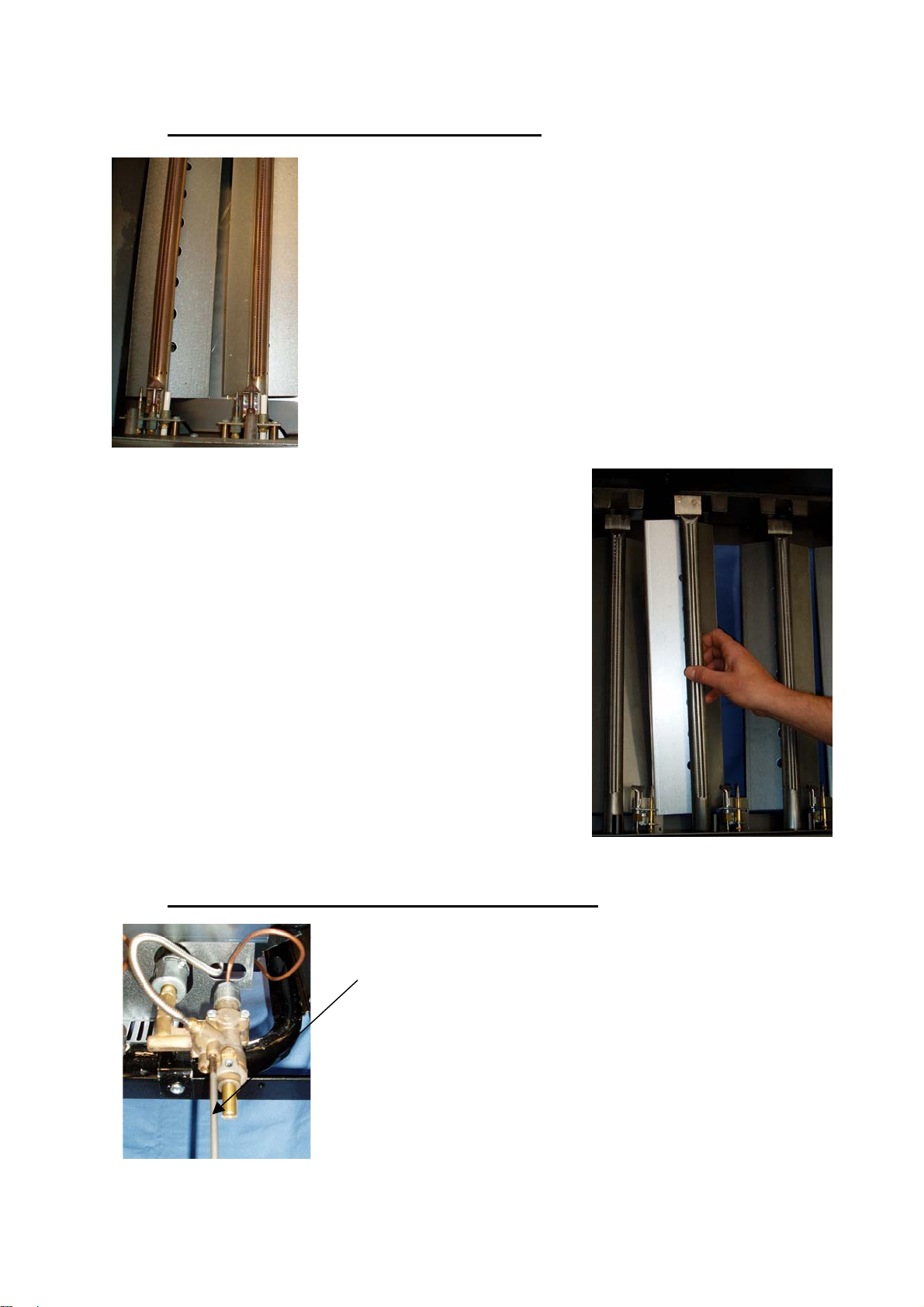
10.1 CLEANING THE BURNER BAFFLES.
The burner baffles are situated underneath the main
burners. Occasionally the baffles may need to be removed
for cleaning with a wire brush. The baffles are removed as
follows.
WARNING! Before attempting to remove the grates ensure
they are at an acceptable temperature to touch. This will
normally take approximately 3 hours after using with the
main burner.
NOTE! THE BURNERS MUST ONLY BE ADJUSTED BY A
COMPETENT AND AUTHORISED PERSON.
BURNER BAFFLES.
PHOTOGRAPH 16.
1. Carefully remove the grates and radiants.
2. To lift out the burner and baffle raise the rear of
the burner and withdraw to one side of the radiant
support.
3. Place the baffle on a flat surface a clean with a
wire brush.
4. Replacement of the burner and baffle is the
reverse of the above procedure.
5. Ensure the open end of the burner locates
correctly onto the gas nozzle.
WITHDRAWING THE
BURNER AND BAFFLE.
PHOTOGRAPH 17.
10.2 ADJUSTING THE PILOT BURNER FLAME.
PILOT BURNER FLAME
ADJUSTMENT SCREW.
TURN ANTI-CLOCKWISE TO
INCREASE FLAME SIZE.
PILOT BURNER FLAME
ADJUSTMENT SCREW.
PHOTOGRAPH 18.
24
NOTE! THE PILOT
BURNER FLAME MUST
ONLY BE ADJUSTED BY A
COMPETENT AND
AUTHORISED PERSON.
Page 27

The pilot burner flame must be stable and have an even and adequate coverage on
the thermocouple without flame lifting. The flame height range should be between 10
to 15 mm.
Air shutters situated on the main burners can be individually adjusted to provide a
blue flame.
To adjust the pilot burner flame, ignite the pilot jet as detailed in section 6.
Using a 4 mm wide slotted screw driver adjust the pilot burner screw anti-clockwise
to increase the flame height or clockwise to reduce the flame height. Ensure the
flame does not lift off the thermocouple when adjusted. This is particularly important
if the appliance is located directly above a strong ventilation system.
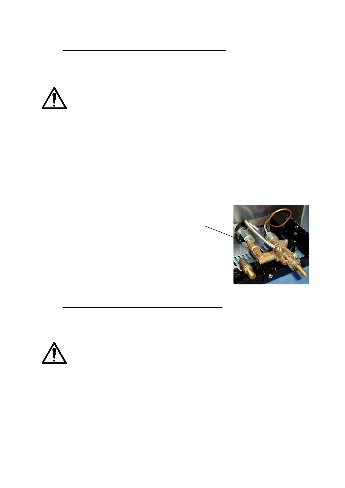
10.3 REPLACING THE PILOT BURNER.
NOTE! THE PILOT BURNER MUST ONLY BE REPLACED BY A COMPETENT AND
AUTHORISED PERSON.
WARNING! Before attempting to remove the grates ensure they are at an
acceptable temperature to touch. This will normally take approximately 3
hours after using with the main burner.
To replace the pilot burner assembly follow the instructions detailed below.
1. Isolate the gas supply to the appliance.
2. Carefully remove the grates and radiants
3. The pilot burner cover is secured using keyhole slots and two screws. Lift the
cover up and away from the locating screws (refer to photograph 19).
4. Partially pull open the drip tray(s).
5. Remove the gas control knobs, front cover securing screws and support the
front cover on the drip tray.
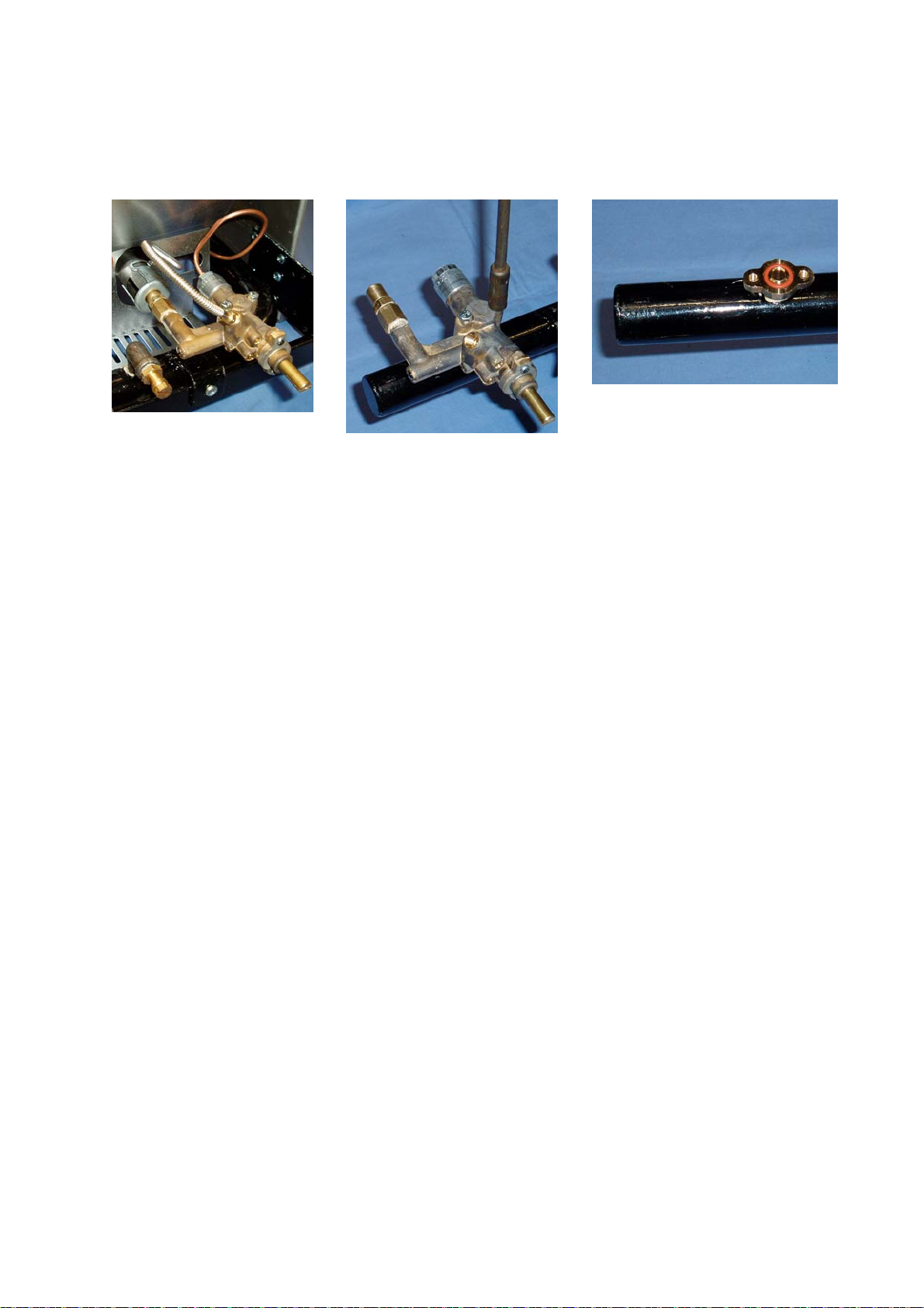
6. Pull off the relevant electrode wire from the piezo igniter.
7. Unscrew the thermocouple brass retaining nut and the pilot burner gas pipe
brass nut (refer to photograph 20).
8. Remove the screw securing the pilot burner assembly to the bracket.
9. Replacement is the reverse of the above procedure. After assembly check for
gas leaks with a suitable leak detection fluid.
Pilot burner
cover.
‘Key hole’
slots.
25
PILOT BURNER DEFLECTOR
COVER. PHOTOGRAPH 19.
Page 28

Electrode
cable
termination.
Piezo
igniter.
Pilot
assembly-
Thermocouple
back nut.
mounting
PILOT BURNER AND
THERMOCOUPLE.
PHOTOGRAPH 20.
Pilot jet
nut.
10.4 REPLACING THE THERMOCOUPLE.
NOTE! THE PILOT BURNER MUST ONLY BE REPLACED BY A COMPETENT AND
AUTHORISED PERSON.
Gas
control
knob.
Front panelretaining screws.
FRONT PANEL RETAINING SCREWS
(SCB60 SHOWN). PHOTOGRAPH 21.
WARNING! Before attempting to remove the grates ensure they are at an
acceptable temperature to touch. This will normally take approximately 3
hours after using with the main burner.
Access to the thermocouple is from underneath the grates.
1. Isolate the gas supply to the appliance.
26
Page 29

2. Carefully remove the grates and radiants
3. The pilot burner cover is secured using keyhole slots and two screws. Lift the
cover up and away from the locating screws (refer to photograph 19).
4. Partially pull open the drip tray(s).
5. Remove the gas control knobs, front cover securing screws and support the front
cover on the drip tray.
6. Unscrew the thermocouple brass retaining nut (refer to photograph 22).
7. Un-screw the retaining nut and withdraw the
thermocouple through the front of the appliance.
8. Replacement is the reverse of the above procedure.
After assembly check for gas leaks with a suitable leak
detection fluid.
Thermocouple
retaining nut.
THERMOCOUPLE RETAINING
NUT. PHOTOGRAPH 22.
10.5 REPLACING THE MAIN BURNER.
NOTE! THE PILOT BURNER MUST ONLY BE REPLACED BY A COMPETENT AND
AUTHORISED PERSON.
WARNING! Before attempting to remove the
grates ensure they are at an acceptable
temperature to touch. This will normally take
approximately 3 hours after using with the main
burner.
Access to the main burner is from underneath the grates.
1 Ensure the unit is cool to the touch before
commencing any work.
2 Isolate the gas supply to the appliance.
3 Carefully remove the grates and radiants
4 The pilot burner cover is secured using keyhole slots
and two screws. Lift the cover up and away from the
locating screws.
5 To remove the main burner and deflector by lifting the
rear end and moving to the left to enable the unit to
be withdrawn.
6 Replacement is the reverse procedure.
7 Ensure the open end of the burner locates correctly
onto the gas nozzle.
MAIN BURNER AND
DEFLECTOR.
PHOTOGRAPH 23.
27
Page 30
10.6 REPLACING THE MAIN BURNER NOZZLE.
NOTE! THE MAIN BURNER NOZZLE MUST ONLY BE REPLACED BY A COMPETENT
AND AUTHORISED PERSON.
WARNING! Before attempting to remove the grates ensure they are at an
acceptable temperature to touch. This will normally take approximately 3
hours after using with the main burner.
1. Ensure the unit is cool to the touch before commencing any work.
2. Isolate the gas supply to the appliance.
3. Carefully remove the grates and radiants
4. Remove the main burner and deflector as detailed in section 11.5
5. Partially pull open the drip tray(s).
6. Remove the gas control knobs, front cover securing screws and support the
front cover on the drip tray.
7. Un-screw the burner nozzle from the gas valve.
8. Replacement is the reverse procedure. Ensure the open end of the burner
locates correctly onto the gas nozzle. After assembly check for gas leaks with
a suitable leak detection fluid.
9. Check the main burner flame pattern and adjust the
air shutter if necessary.
Main burner
nozzle.
MAIN BURNER NOZZLE.
PHOTOGRAPH 24.
10.7 REPLACING THE GAS CONTROL VALVE.
NOTE! THE GAS CONTROL VALVE MUST ONLY BE REPLACED BY A COMPETENT
AND AUTHORISED PERSON.
WARNING! Before attempting to replace the gas control valve ensure the
appliance is at an acceptable temperature to touch.
1. Isolate the gas supply to the appliance.
2. Remove the gas control knobs, 4 off front cover securing screws and front
cover.
3. Unscrew the pilot burner gas supply pipe nut
4. Unscrew the thermocouple retaining nut.
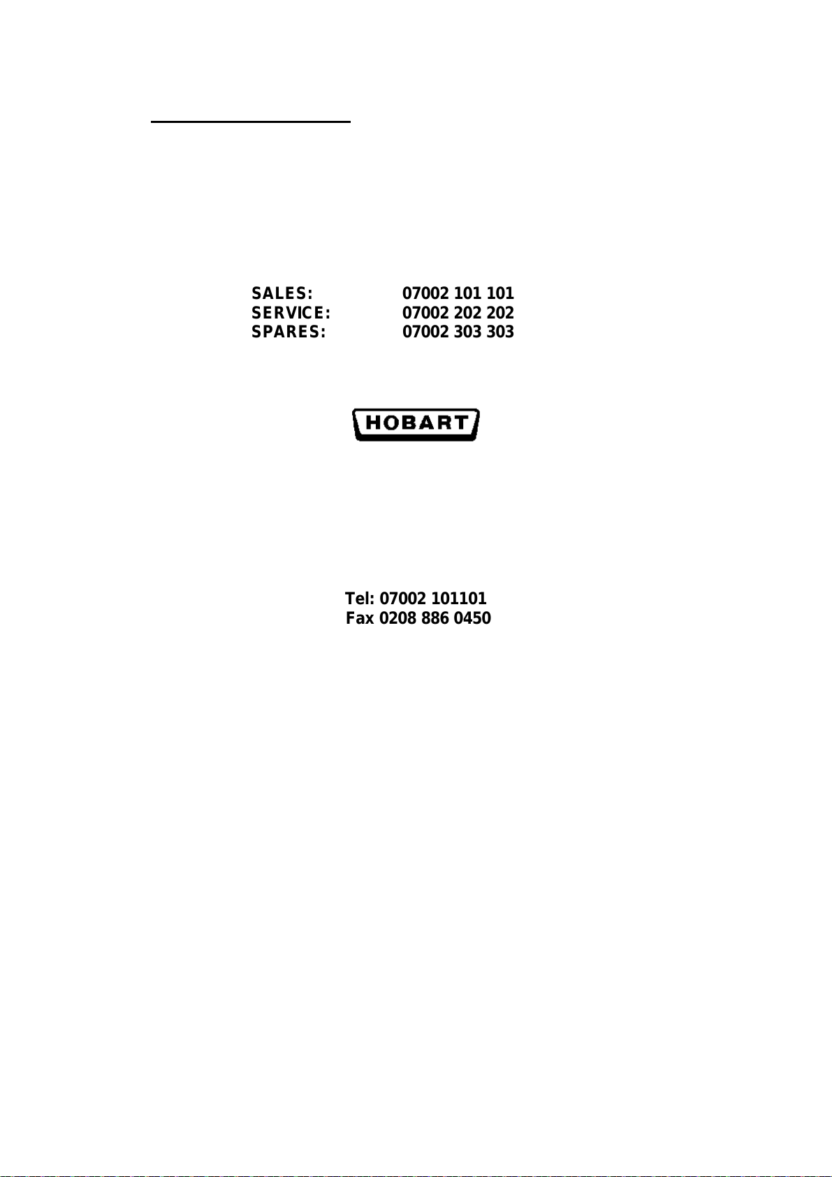
5. Remove the two screws securing the gas valve to the manifold and carefully
lift off the valve assembly.
6. Check the condition of the sealing O ring and replace if necessary.
28
Page 31
7. Replacement of the gas valve is the reverse of the above procedure. After
assembly check for gas leaks with a suitable leak detection fluid.
GAS CONTROL VALVE
SEAT AND O RING.
PHOTOGRAPH 27.
GAS CONTROL
VALVE ASSEMBLY.
PHOTOGRAPH 25.
GAS CONTROL VALVE.
PHOTOGRAPH 26.
29
Page 32

11.0 FAULT FINDING AND REMEDIAL ACTION.
NOTE! ONLY A FULLY TRAINED AND COMPETENT PERSON MUST
USE, INSTALL, MAINTAIN AND SERVICE THE SCB SUPER CHAR
BROILER.
11.1 FAULT FINDING SUMMARY.
Fault Possible cause Remedy
Pilot flame
fails to ignite.
the
electrode.
Pilot flame
fails to
remain
ignited
Main burner
fails to ignite.
Smell of gas Leak from pipe or joint. Isolate gas supply, ventilate room
Gas supply isolated to appliance Check gas isolation valve and open
if necessary.
Gas supply pipe requires purging Purge gas supply pipe.
Blocked pilot jet Remove pilot jet and clean
Failed regulator Check regulator and replace as
necessary.
Incorrect gas regulator pressure
setting.
Gas control knob not set to correct
position.
Failed gas control valve. Check and replace as necessary.
Piezo igniter failure. Replace the piezo igniter.No spark at
Poor electrical connection to the
piezo igniter
Thermocouple not heated sufficiently. Wait 3 minutes and ignite pilot
Pilot flame too small Check flame height and adjust as
Incorrect gas regulator pressure
setting.
Failed thermocouple. Check and replace as necessary.
Failed gas control valve. Check and replace as necessary.
Gas supply isolated to appliance Check gas isolation valve and open
Incorrect gas regulator pressure
setting.
Failed gas control valve. Check and replace as necessary.
Appliance still fails to operate Call local Hobart service centre.
Pressure regulator requires
adjustment.
Re-adjust control knob to pilot
flame position.
Check cable connection to the
piezo igniter.
burner, hold the control knob in for
20 seconds to heat the
thermocouple.
necessary.
Pressure regulator requires
adjustment.
if necessary.
Pressure regulator requires
adjustment.
and call Hobart Service.
30
Page 33

12.0 COMPLETE SCB SUPPER CHAR BROILER MAINTENANCE
SERVICING
A HOBART TRAINED AND COMPETENT PERSON SHOULD CARRY
OUT SERVICING.
Do not remove any covers or loosen any fittings while the SCB Char broiler is
operating. Ensure the gas supply has been isolated before attempting to service or
move the appliance.
It is recommended that the appliance be serviced regularly depending on the
customer usage as summarised in the table below. Refer to section 11 for more
detailed maintenance information. It is recommended that servicing is only carried
out by Hobart trained service personnel. For further information on Hobart service
contracts contact our service division on 07002 202 202.
Table 6. RECOMMENDED SERVICE INTERVALS.
Hours of use per day Service interval
10 to 12 hours per day, 7 days per week Every 30 to 60 days
4 to 6 hours per day, 5 days per week Every 3 months
Limited daily usage Every 6 months
31
Page 34

13.0. RECOMMENDED SPARE PARTS.
Part number Description SCB25CE SCB36CE SCB47CE SCB60CE SCB72CE
Qty per
appliance
00-722131 Grate, angled 6 rib 3 1
00-710424 Grate, angled 7 rib 4 6 8 8 12
00-710423-1 Grate, straight 6 rib 3 1
00-710423 Grate, straight 7 rib 4 6 8 8 12
00-710453-1 Burner, natural gas 4 6 8 11 13
00-700871 Burner, LPG 4 6 8 11 13
00-739029-1 Regulator, natural
gas
00-739029-2 Regulator, LPG 1 1 1 1 1
00-739456 Heat deflector 4 6 8 11 13
00-739164 Grease channel 1
00-739280 Grease channel 1
00-739083 Grease channel 1
00-739285 Grease channel 1
00-739288 Grease channel 1
00-710407 Radiant 4 6 8 11 13
00-719255-3 Knob, control red 4 6 8 11 13
00-719260 Leg, adjustable 4 4 4 4 4
00-738986-1 Thermocouple 4 6 8 11 13
00-739299-1 Piezo ignitor c/w
earth strip single
spark
00-739299-2 Piezo ignitor twin
spark
00-739491 Pilot burner c/w
electrode, natural
gas
00-711339-NPilot orifice, natural
gas
00-711339-PPilot orifice LPG 4 6 8 11 13
11111
23456
4681113
4681113
Qty per
appliance
Qty per
appliance
Qty per
appliance
11
Qty per
appliance
GE-E-1-38 Magnet unit flame
failure
00-719951-51Orifice, main burner
#51, natural gas
00-719951-57Orifice, main burner
#57, LPG
00-720516-4 Gas control valve,
natural gas
24132421 Tap, test nipple 1 1 1 1 1
00-739265-1 Drip pan 1
00-739265-2 Drip pan 1
00-739265-3 Drip pan 2
00-739265-4 Drip pan 2
00-739265-5 Drip pan 2
00-739037 Grate lifting tool (Optional extra)
00-739397 Fry plate kit (Optional extra)
4681113
4681113
4681113
4681113
32
Page 35
14.0 SERVICE CONTACTS
Hobart trained service technicians strategically located at the listed Hobart branches
are prepared to give you fast, efficient and reliable service. Protect your investment
by having a Hobart inspection contract, which assures the continued, efficient
operation of your Hobart machines, spares and accessories.
For further detail contact: -
SALES: 07002 101 101
SERVICE: 07002 202 202
SPARES: 07002 303 303
Continued product improvement is a Hobart policy, specifications may change without notice.
Hobart UK.
Hobart House,
51 The Bourne,
Southgate,
London
N14 6RT
Tel: 07002 101101
Fax 0208 886 0450
PLE200513 – C 08-08 EU8079
33
 Loading...