


Henny Penny
Rotisserie
Model SCR-6/8
TECHNICAL MANUAL

SCR-6/8
TABLE OF CONTENTS
Section |
|
|
Page |
Section 1. |
TROUBLESHOOTING ........................................................................................... |
1-1 |
|
|
1-1. |
Introduction .................................................................................................... |
1-1 |
|
1-2. |
Safety ............................................................................................................. |
1-1 |
|
1-3. |
Troubleshooting .............................................................................................. |
1-1 |
|
1-4. |
Error Codes ................................................................................................... |
1-3 |
Section 2. |
MAINTENANCE ..................................................................................................... |
2-1 |
|
|
2-1. |
Introduction .................................................................................................... |
2-1 |
|
2-2. |
Maintenance Hints ......................................................................................... |
2-1 |
|
2-3. |
Halogen Lamp Replacement ......................................................................... |
2-1 |
|
2-4. |
Blower Replacement ..................................................................................... |
2-2 |
|
2-5. |
Thermal Sensor Replacement ....................................................................... |
2-3 |
|
2-6. |
Contactor ....................................................................................................... |
2-4 |
|
2-7. |
Drive Motor Replacement Kit ....................................................................... |
2-5 |
|
2-8. |
Rotation Control Switch ................................................................................. |
2-6 |
|
2-9. |
Capacitor Replacement - Blower Motor ....................................................... |
2-8 |
|
2-10. |
Capacitor Replacement - Drive Motor .......................................................... |
2-8 |
|
2-11. |
Door Sensor Replacement ............................................................................. |
2-9 |
|
2-12. |
Socket - Halogen Lamp ................................................................................. |
2-10 |
|
2-13. |
Power Switch ................................................................................................ |
2-10 |
|
2-14. |
Radiant Heaters ............................................................................................. |
2-11 |
|
2-15. Control Board Speaker Replacement ............................................................ |
2-12 |
|
|
2-16. |
Meat Probe Receptacle Replacement ........................................................... |
2-12 |
|
2-17. |
Control Board Replacement .......................................................................... |
2-13 |
|
2-18. |
Relays ............................................................................................................ |
2-13 |
|
2-19. |
High Limit ...................................................................................................... |
2-15 |
|
2-20. |
Wiring Diagrams ............................................................................................ |
2-17 |
Section 3. |
PARTS INFORMATION ......................................................................................... |
3-1 |
|
|
3-1. |
Introduction .................................................................................................... |
3-1 |
|
3-2. |
Genuine Parts ................................................................................................ |
3-1 |
|
3-3. |
How To Order ............................................................................................... |
3-1 |
|
3-4. |
Prices ............................................................................................................. |
3-1 |
|
3-5. |
Delivery ......................................................................................................... |
3-1 |
|
3-6. |
Warranty ........................................................................................................ |
3-1 |
|
3-7. Recommended Spare Parts for Distributors .................................................. |
3-1 |
|
i |
FM06-011 |
306 |
|
Revised 4-13-12 |
|
ii |
803 |
SCR-6/8
SECTION 1. TROUBLESHOOTING |
|
1-1. INTRODUCTION |
This section provides troubleshooting information in the |
|
form of an easy to read table. |
|
If a problem occurs during the first operation of a new |
|
rotisserie, recheck the installation per the Installation |
|
Section of the Operator’s Manual. |
|
Before troubleshooting, always recheck the Operation |
|
Procedures Section of the Operator’s Manual. |
1-2. SAFETY |
Where information is of particular importance or is safety related, |
|
the words NOTICE, CAUTION, or WARNING are used. Their |
|
usage is described below. |
|
SAFETYALERT SYMBOL is used with DANGER, |
|
WARNING, or CAUTION which indicates a personal injury |
|
type hazard. |
|
NOTICE is used to highlight especially important information. |
|
CAUTION used without the safety alert symbol indicates |
|
a potentially hazardous situation which, if not avoided, may |
|
result in property damage. |
|
CAUTION used with the safety alert symbol indicates a |
|
potentially hazardous situation which, if not avoided, |
|
may result in minor or moderate injury. |
|
WARNING indicates a potentially hazardous situation |
|
which, if not avoided, could result in death or serious |
|
injury. |
1-3. TROUBLESHOOTING |
To isolate a malfunction proceed as follows: |
|
1. Clearly define the problem or symptom and when it occurs. |
|
2. Locate the problem in the troubleshooting table. |
3. Review all possible causes, then one at a time work through the list of corrections until the problem is solved.
If maintenance procedures are not followed correctly, injuries and/or property damage could result.
203 |
1-1 |

SCR-6/8
1-3. TROUBLESHOOTING (Continued)
Problem |
Cause |
Correction |
|
COOKING SECTION |
|
Product Color Not Correct: |
|
|
A. Too Dark |
• Temperature too high |
• Check probe position; see Thermal |
|
|
Sensor Replacement Section |
|
|
• Check temperature setting in the |
|
|
program mode; see Programming |
|
|
Section in Operator’s Manual |
|
|
• Remove and replace defective probe |
|
|
|
B. Too Light |
• Temperature too low |
• Check probe position; see Thermal |
|
|
Sensor Replacement Section |
|
|
• Check temperature setting |
|
|
• Remove and replace defective |
|
|
probe |
|
|
• Allow proper preheat time |
|
|
• Be sure to select the correct product |
|
|
button |
|
|
|
C. Dry Product |
• Moisture loss prior to cooking |
• Use fresh product |
|
• Overcooking the product |
• Reduce cooking time |
|
|
• Reduce cooking temperature |
General Product |
|
|
|
|
|
Problems: |
|
|
A. Meat Separation |
• Overcooking |
• Check cooking time |
From Bone |
• Product not fresh |
• Use fresh product |
|
|
|
|
POWER SECTION |
|
|
|
|
With power switch in |
• Open circuit |
• Check to see that unit is plugged in |
POWER position, the |
|
• Check the breaker or fuse at supply |
rotisserie is completely |
|
box |
inoperative. |
|
• Check voltage at wall receptacle |
|
|
• Check Power switch; replace if |
|
|
defective |
|
|
• Check cord and plug |
|
|
|
Unit will not heat |
• Blown fuse or tripped circuit |
• Reset breaker or replace fuse |
|
breaker at supply box |
|
|
• Blown fuse PC Board |
• Check fuse on PC board |
|
• Faulty contactor |
• Check contactor per Contactor |
|
|
Section |
|
• Faulty Power switch |
• Check power switch per Power |
|
|
Switch Section |
|
• Faulty PC Board |
• Remove and replace control board |
|
• Faulty cord and plug |
• Check cord and plug and power at |
|
|
wall receptacle |
|
• Faulty relay |
• Check relay per section; see Relays |
|
|
Section |
|
|
|
1-2 |
203 |

SCR-6/8
1-3. TROUBLESHOOTING (Continued)
Problem |
Cause |
Correction |
Product not done
Unit overheating (product too dark)
Timers fail to run, or won’t turn off
Timer will not beep
• Low or improper voltage |
• |
Use a meter and check the |
|
|
receptacle against data plate |
• Weak or burnt out elements |
• |
Check heating element(s) per |
|
|
Radiant Heaters Section |
• Points in contactor bad |
• |
Check contactor per Contactor |
|
|
Section |
• Bad relay |
• |
Replace relay per Relays Section |
• Wire(s) loose |
• |
Tighten |
• Burnt or charred connector |
• |
Replace wire and clean connectors |
|
|
|
• Probe not properly in position |
• Check probe position; see Thermal |
|
|
|
Sensor Replacement Section |
• Check probe calibration |
• |
If probe is more than 10oF out of |
|
|
calibration, replace probe |
• Faulty control board |
• |
Replace control board per Control |
|
|
Board Replacement Section |
• Check contactor for not |
• |
Check for faulty contactor per |
opening |
|
Contactor Section |
|
|
|
• Low voltage |
• |
Check voltage at receptacle to |
|
|
match unit voltage |
|
• Check voltage at transformer |
|
• Faulty display board |
• |
Replace display board |
• Indented or torn decal |
• |
Replace control decal |
• Faulty speaker |
• Replace speaker per Speaker |
|
|
|
Replacement Section |
|
|
|
1-4. ERROR CODES - The control has built-in self-diagnostic error codes that will show on the display.
Error Code |
|
Cause |
|
Correction |
|
|
|
|
|
“E-6” Prob Err |
• |
Temperature probe failure |
• Reconnect probe to board, or |
|
|
|
|
|
replace probe |
“E-4” ctrl hot |
• |
Control board temperature too hot |
• Replace or clean blower |
|
“E-50” CPU Chip |
• |
CPU RAM error |
• |
“E-50”, “E-51”, “E-53”, & “E-41” |
“E-51” rA-CHIP |
• |
External RAM error |
|
are software errors |
“E-53” ro-CHIP |
• |
External ROM error |
• Reinitialize the board, and if error |
|
data Err |
• |
Scrambled memory |
|
persists, replace “E-41” board |
|
|
|
|
|
“E-5” too hot |
• |
Software high limit (air temperature |
• |
Change control board or contactor |
|
|
too hot) |
• |
Replace blower |
|
|
|
|
|
803 |
1-3 |

SCR-6/8
THIS
PAGE
INTENTIONALLY
LEFT
BLANK.
1-4 |
803 |
|
|
SCR-6/8 |
|
|
|
|
|
|
|
SECTION 2. MAINTENANCE |
|
|
|
|
|
2-1. INTRODUCTION |
This section provides procedures for the checkout and replacement of |
||
|
|
the various parts used within the rotisserie. Before replacing any parts, |
|
|
|
refer to the Troubleshooting Section. It will aid you in determining the |
|
|
|
cause of the malfunction. |
|
2-2. MAINTENANCE HINTS |
1. You may want to use a multimeter to check the electric |
||
|
|
components. |
|
|
|
2. When the manual refers to the circuit being closed, the |
|
|
|
multimeter should read zero unless otherwise noted. |
|
|
|
3. When the manual refers to the circuit being open, the multimeter |
|
|
|
will read infinity. |
|
2-3. HALOGEN LAMP |
|
|
|
|
REPLACEMENT |
|
|
|
|
To avoid electrical shock or property damage, move the |
|
|
|
power switch to OFF and disconnect main circuit |
|
|
|
breaker, or unplug cord at wall receptacle. |
|
|
|
Light bulbs and surrounding surfaces may be hot. |
|
|
|
Severe burns could result. |
|
|
|
1. Push in and twist bulb counterclockwise to remove defective bulb. |
|
|
|
2. Use the foam packing around new bulb, and push new bulb into |
|
|
Step 2 |
socket. Twist clockwise to lock into place. |
|
|
|
When installing the new bulb, do not touch light bulb with |
|
|
|
fingers. Wrap the foam packing around bulb to install the |
|
|
|
bulb. Failure to follow these instructions could cause dam- |
|
|
|
age to bulb. |
|
|
|
3. Restore power to unit. |
|
203 |
2-1 |
SCR-6/8
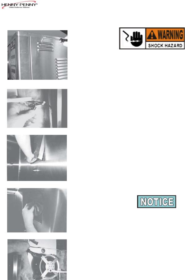
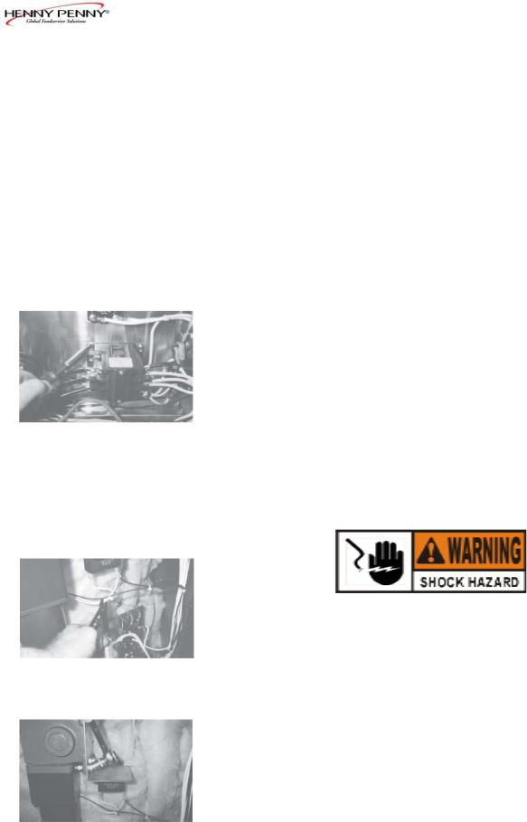
2-4. BLOWER REPLACEMENT |
1. Remove electrical power to unit. |
|
|
To avoid electrical shock or property damage, move |
|
|
the power switch to OFF and disconnect main circuit |
|
|
breaker, or unplug cord at wall receptacle. |
|
2. |
Using Phillips head screwdriver, remove the side panel |
Step 2 |
|
closest to the controls. |
|
3. |
Remove electrical wires from wire nuts. |
|
4. |
Remove discs and rod from inside of unit. (See Cleaning |
|
|
Section in Operator’s Manual.) |
Step 3 |
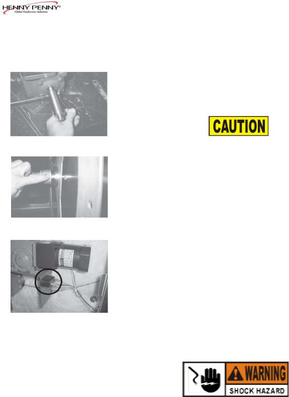
5. |
Unscrew knob and lift drive-side vent panel up and |
|
|
out of unit. |
|
6. |
Loosen thumb screw and pull out on fan blade and |
|
|
remove from shaft. |
|
7. |
Using a 7/16" nut driver, remove the nuts securing |
|
|
the blower to the unit, and remove blower from unit. |
Step 5 |
8. |
Replace with new blower in reverse order. |
When placing fan blade back onto shaft, rotate fan blade on the blower shaft, while holding the blower wheel inside the control area. The fan blade should snap onto a pin at the base of the shaft.
Step 6
Step 7
2-2 |
203 |
SCR-6/8
2-5. THERMAL SENSOR
REPLACEMENT |
|
|
|
1. |
Remove electrical power to unit. |
|
|
To avoid electrical shock or property damage, move the |
|
|
power switch to OFF and disconnect main circuit |
|
|
breaker, or unplug cord at wall receptacle. |
|
2. |
Remove the side panel closest to the controls. |
Step 2 |
|
|
|
3. |
Unplug probe from control PC board. |
|
4. |
Press down on the probe bracket and pull probe from |
|
|
bracket, or using 3/8" socket, remove nut securing probe |
|
|
bracket to unit and remove bracket and probe from unit. |
|
5. |
Remove vent panels from inside unit. (See Cleaning |
|
|
Section of Operator’s Manual.) |
Step 3 |
6. |
Install new probe in reverse manner, exposing the probe |
|
|
1½” (38 mm) inside cabinet. |
1½ inch (38 mm) probe position is important. Improper positioning causes erroneous temperature readings.
7.Plug probe onto P2, a 2 pin connector.
Step 6
203 |
2-3 |
SCR-6/8
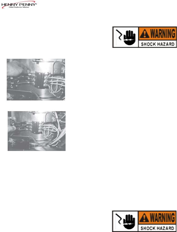
2-6. CONTACTOR |
1. Remove electrical power to unit. |
To avoid electrical shock or property damage, move the power switch to OFF and disconnect main circuit breaker, or unplug cord at wall receptacle.
Checkout:
2. Remove the side panel closest to the controls.
Step 3
3.Label and remove the wires from contactor.
4.Perform a check on the contactor as follows:
Step 4
Test Points from 23 to 29 from 24 to 28 from 25 to 27 from 22 to 26
Results open circuit open circuit open circuit ohm reading 415
Checkout - power supplied:
To avoid electrical shock, make connections before applying power, take reading, and remove power before removing meter leads. The following checks are performed with the wall circuit breaker closed and the main power switch in the ON position.
5. With power reapplied, let unit start heating up.
2-4 |
203 |
2-6. CONTACTOR (Continued)
Step 7
2-7. DRIVE MOTOR REPLACEMENT KIT
Step 4
Step 5
SCR-6/8
6. Check voltage as follows: |
|
Test Points |
Results |
from terminal 29 to 28 |
The voltage |
from terminal 27 to 28 |
should read the |
from terminal 27 to 29 |
same at each terminal. |
Replacement:
If contactor proves defective:
7.Remove the four screws securing the contactor to the bracket and remove contactor.
8.Install new contactor, replace wires, and replace side panel.
9.Restore power to unit.
1.Remove electrical power to unit.
To avoid electrical shock or property damage, move the power switch to OFF and disconnect main circuit breaker, or unplug cord at wall receptacle.
2.Remove rod and discs from unit. (See Cleaning Section of the Operator’s Manual.)
3.From the control side of the unit, remove the right side panel.
4.Cut the three wires from the motor.
5.Using 9/16" socket, remove the bolts securing the motor to the bracket, and pull motor from unit.
1207 |
2-5 |
2-7. DRIVE MOTOR REPLACEMENT KIT (Continued)
Step 6
Step 8
Step 11
2-8. ROTATION CONTROL SWITCH
SCR-6/8
6.Slide extension hub (on motor) into slot on the unit, and bolt the motor to the bracket. Snug, but don’t tighten nuts.
7.Install discs into unit and place rod into place.
8.Adjust motor on bracket so no more than 1/16" (1.6 mm) gap is present and the end of the rod is even all around hub.
The rod must not have much “play” in it from the disc hub. The gap between the end of the rod and the hub should not be more than 1/16" (1.6 mm) or damage to rod and disc assembly could occur.
9.Once rod is lined up, tighten nuts on bracket.
10.Splice wires of motor onto the cut wires, according to colors.
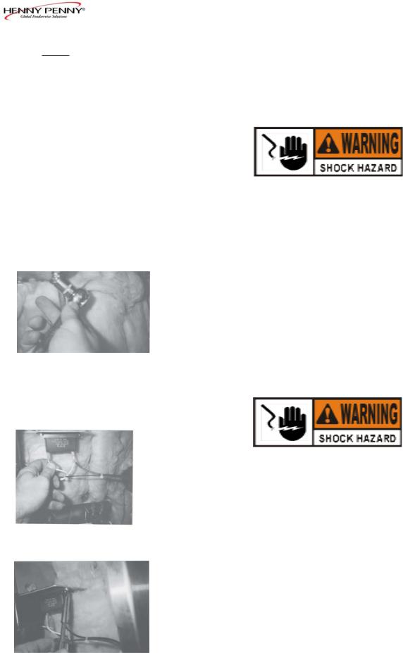
11.Remove wires to the drive motor capacitor, mounted under the motor. Remove the capacitor from the unit and replace with the one in the kit.
12.Replace side panel and restore power.
1.Remove electrical power supplied to unit.
To avoid electrical shock or property damage, move the power switch to OFF and disconnect main circuit breaker, or unplug cord at wall receptacle.
2-6 |
1207 |

SCR-6/8
2-8. ROTATION CONTROL
SWITCH (Continued)
Step 3
Step 5
Step 6 |
Back Ring |
Step 7
2.Remove screws securing the side panel closest to the controls.
3.Remove and label wires from terminals of switch.
4.Take a continuity reading across terminals. If meter shows constant open or closed circuit each time the button is pushed, the switch is defective.
5.For SCR 6, SN: CA0603001 & below
SCR 8, SN: CB0602054 & below
Unscrew the back ring of switch and pull out switch from the front of the unit.
For SCR 6, SN: CA0603002 & above SCR 8, SN: CB0602055 & above
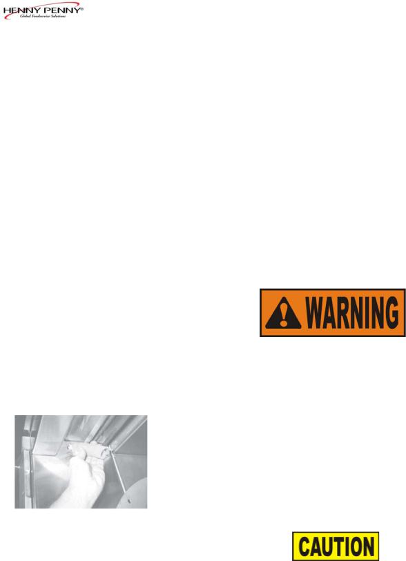
Remove the terminal block assembly by inserting a small, flat-head screwdriver in the opening at the top of the switch and prying up, as shown in Figure 1. Make sure the end of the screwdriver pries up on the silver release bar. Unscrew the back ring and pull out switch from the front of the unit.
6.Once removed from the packaging, remove the back ring from new switch.
7.Insert the new switch from the front, aligning the arrow on the swtich with the notch in the front panel and then secure the switch to the panel with the back ring.
8.Fit the large notch in the switch onto the “cradle” of the terminal block assembly and snap the two pieces together.
Switch
Step 8 |
Terminal Block Assy |
|
9.Replace wires on terminals.
10.Replace side panel and restore power.
306 |
2-7 |
SCR-6/8
2-9. CAPACITOR REPLACE-
MENT - BLOWER MOTOR
1. Remove electrical power supplied to unit.
To avoid electrical shock or property damage, move the power switch to OFF and disconnect main circuit breaker, or unplug cord at wall receptacle.
|
2. |
Remove the side panel closest to the controls. |
|
3. |
Disconnect wires from wire nuts. |
|
4. |
Using a 1/2" socket, remove nut securing capacitor to |
|
|
bracket and remove capacitor. |
|
5. |
Install new capacitor in reverse order. |
Step 4 |
|
|
2-10. CAPACITOR REPLACE- |
1. Remove electrical power supplied to unit. |
|
MENT - DRIVE MOTOR |
|
|
To avoid electrical shock or property damage, move the power switch to OFF and disconnect main circuit breaker, or unplug cord at wall receptacle.
2. Remove side panel closest to controls.
Step 3
3.Disconnect wires from capacitor.
4.Remove the three Phillips head screws from the capacitor, and remove capacitor from unit.
5.Install new capacitor in reverse order.
Step 4
2-8 |
306 |
 Loading...