


TABLE OF CONTENTS |
|
WARRANTY STATEMENT ................................................. |
PAGE 2 |
INTRODUCTION ................................................................. |
PAGE 3 |
INSTALLATION .................................................................. |
PAGE 3 |
PARTS IDENTIFICATION ................................................... |
PAGE 4 |
EQUIPMENT SET-UP AND CLOSE PROCEDURES ........ |
PAGE 10 |
TROUBLESHOOTING ........................................................ |
PAGE 12 |
NON-SCHEDULED MAINTENANCE.................................. |
PAGE 13 |
ORDERING PARTS ............................................................ |
PAGE 20 |
FM01-688

INTRODUCTION
This staging cabinet is a basic unit of food processing equipment designed to hold hot foods at proper temperature in commercial food operations. This cabinet will keep hot foods humid while maintaining temperature.
Features:
•Easily cleaned
•Front panel programmable time and temperature
•Easy access to Electrical Components
•Moist heat
•Removable control module
•Clear glass front door
•Lift out racks
•Venting system to limit humidity levels in cabinet
Hazard Communication Standard (HCS) - The procedure in this chapter include the use of chemical products. These chemical products. These chemical products will be highlighted with bold face letters followed be the abbreviation (HCS). See the Hazard Communication Standard (HCS) Manual for the appropriate Material Safety Data Sheet(s) (MSDS).
This piece of equipment is made in America and has American sizes on hardware. All metric conversions are approximate and vary in size.
INSTALLATION
WARNING: Do not puncture the skin of the Staging Cabinet with any tools or fastening devices. Electrical shock or component damage could result.
The staging cabinet should be placed on an approved table or shelf to allow easy access for loading and unloading of product. For proper operation, the cabinet must be level.
Electrical Connection
The Staging Cabinet is available from the factory as a 120 VAC unit for domestic use, or as a 240 VAC unit for foreign use. The data plate on the side of the unit will specify the correct electrical supply. The unit requires a grounded receptacle with a separate electrical line protected by a fuse or circuit breaker of the proper rating.
WARNING: The cabinet must be adequately and safely grounded according to local electrical codes to prevent the possibility of electrical shock.
Cabinet Preparation
When the cabinet is turned on for the first time, you may experience the following:
A.A burning odor.
B.Slight smell of smoke.
This indicates oils used on stainless steel and the new electrical connections are burning off residue.
It will take 3 to 4 hours of burn off to eliminate this inconvenience. The burning off procedure should be done the day before you intend to use the cabinet. It should be done in a ventilated area away from the kitchen and customers. After the burn off procedure is complete, thoroughly clean the staging cabinet following the daily cleaning procedures.
3
 14
14
13
1
2 |
12 |
11
3 (2) (4) |
10 |
A C |
|
|
|
|
|
|
|
9 |
4 (4) (4) |
|
|
|
|
|
|
|
N O |
|
|
|
|
|
|
|
|
|
5 |
6 |
7 (2) |
|
8 |
|
|
|
B |
|
||||
|
|
|
|
|
|
|
|
|
|
PART |
|
|
|
|
|
ITEM |
|
NO. |
|
DESCRIPTION |
QTY |
FUNCTION |
|
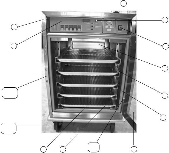
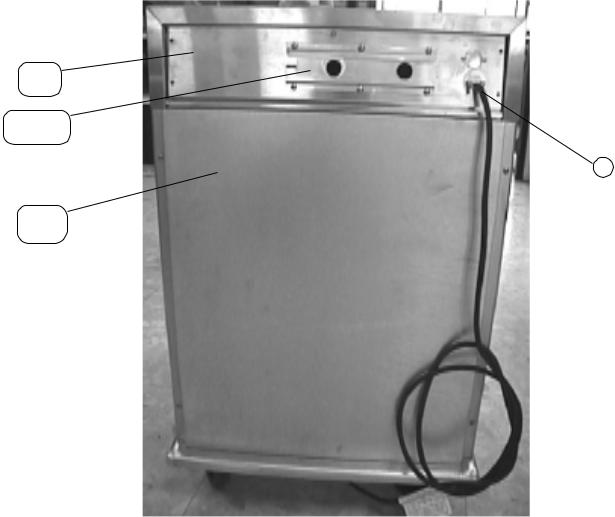
1 |
|
25602 |
|
Module Top |
|
1 |
Covering for components |
2 |
|
52347 |
|
Control Panel Decal |
1 |
Covering for digital display |
|
3 |
|
27739 |
|
Strike Plate Only |
1 |
Latches door closed |
|
|
|
25937 |
|
Strike Plate & |
Latch Assy. |
1 |
|
4 |
|
27154 |
|
Caster w/Brake |
2 |
Allows unit to be mobile |
|
|
|
27155 |
|
Caster |
|
2 |
|
5 |
|
05030 |
|
Bun Pan Grid |
|
5 |
Supports the product |
6 |
|
05019 |
|
Bun Pan |
|
5 |
Supports the grid |
7 |
|
25702 |
|
Hinge Assy. |
|
2 |
Allows the door to swing |
|
|
27146 |
|
Chrome Hinge Cover Only |
2 |
Covers hinge |
|
8 |
|
54352 |
|
Glass Door Assy. - RH |
1 |
Allows access to interior |
|
|
|
54353 |
|
Glass Door Assy. - LH |
|
|
|
|
|
41801 |
|
Glass Only |
|
1 |
Allows viewing to interior |
9 |
|
25793 |
|
Door Gasket |
|
1 |
Seals the door to the unit |
10 |
|
25957 |
|
Rack/Air Duct Assy. |
2 |
Supports the pans and grids |
|
11 |
|
25879 |
|
Water Box Assy. |
1 |
Holds water for humidity |
|
12 |
|
43768 |
|
Rocker Switch |
|
1 |
Powers the controls |
13 |
|
38367 |
|
Knob - Vented Module |
1 |
Allows opening of vents |
|
14 |
|
25704 |
|
Module Access Panel |
1 |
Allows access to components |
|
|
|
|
|
|
4 |
|
|
15
20 (4) |
17 (6) |
18 (4) |
19 |
16 (2) |
J |
D |
D |
|
D |
|
PART |
|
|
|
ITEM |
NO. |
DESCRIPTION |
QTY |
FUNCTION |
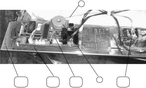
15 |
29523 |
Temperature Probe |
1 |
Senses interior cabinet tem- |
|
|
|
|
perature |
16 |
ME90-003 |
Relay - 12 volt Coil |
1 |
Routes power to heater |
17 |
51117RB |
Display PC Board |
1 |
Displays time and tempera- |
|
|
|
|
ture |
18 |
44741RB |
Control PC Board |
1 |
Powers digital display and |
|
|
|
|
temperature controls |
19 |
40500 |
Replaceable Beeper |
1 |
Sounds a tone when a button |
|
|
|
|
is pressed and at the end of a |
|
|
|
|
timing cycle |
20 |
51115 |
Control Panel Weld Assy. |
1 |
Sheet metal panel that control |
|
|
|
|
components attach to |
|
|
|
|
|
5
25 |
24 |
26 |
23 |
27 (G) |
22 (F) |
4 |
4 |
28
21 (E)
2
|
PART |
|
|
|
ITEM |
NO. |
DESCRIPTION |
QTY |
FUNCTION |
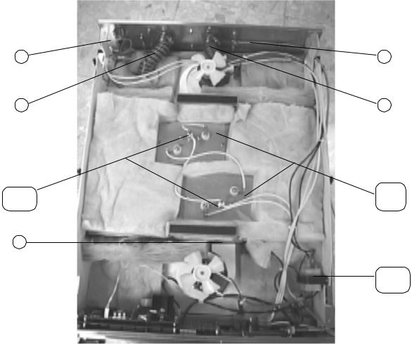
21 |
TS22-006 |
Transformer - 115 volt |
1 |
Reduces voltage to 12 volts |
|
28979 |
Transformer - 240 volt |
1 |
|
22 |
25738 |
Heater - 120 volt - 750 watt |
2 |
Heats the cabinet |
23 |
25964 |
Intake Hose |
1 |
Pulls outside air into cabinet |
24 |
28155 |
Vent Cable |
1 |
Opens vents |
25 |
ME50-021 |
Terminal Block |
1 |
Junction for power cord |
26 |
25963 |
Exhaust Hose |
1 |
Allows interior cabinet air to |
|
|
|
|
escape |
27 |
18201 |
Temperature High Limit |
2 |
Safety for overheating |
28 |
25619 |
Blower Outlet Gasket |
1 |
Seals blower to heater box |
|
|
|
|
|
6
29
33
30
(4) (4) (4) (4) H I P Q
32
31
|
PART |
|
|
|
ITEM |
NO. |
DESCRIPTION |
QTY |
FUNCTION |
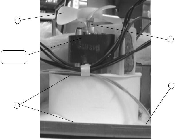
29 |
25706 |
Fan Blade |
2 |
Cools the components |
30 |
25751 |
Blower Motor - 120 volt |
2 |
Circulates air in unit |
|
25752 |
Blower Motor - 240 volt |
2 |
|
31 |
25698 |
Blower Plate Gasket |
4 |
Seals the blower housing to |
|
|
|
|
the blower box |
32 |
25627 |
Gasket |
2 |
Seals the blower box to the |
|
|
|
|
unit |
33 |
25768 |
Fan Blade Spacer |
2 |
Keeps fan blade at the correct |
|
|
|
|
spacing on motor shaft |
7
28(5) K
29 (6) (6) A L
31
30(4) M
|
PART |
|
|
|
ITEM |
NO. |
DESCRIPTION |
QTY |
FUNCTION |
28 |
25944 |
Rear Panel Studweld Assy. |
1 |
Rear components attach to |
29 |
25919 |
Vent Slide |
1 |
Reduces voltage to 12 volts |
30 |
25954 |
Outside Panel Assy. |
1 |
Covers rear of unit |
31 |
31584 |
Power Cord Assy. |
1 |
Provides power to unit |
8
 Loading...