


|
SCR-6/8 |
|
|
|
|
|
SECTION 2. INSTALLATION |
|
2-1. INTRODUCTION |
This section provides the installation instructions for the Henny |
|
|
Penny Rotisserie. |
|
|
Installation of this unit should be performed by a qualified |
|
|
service technician. The installation of this unit must conform to |
|
|
all local, state, and federal codes. |
|
|
Do not puncture the rotisserie with any objects such as |
|
drills or screws as electrical shock, or component |
|
damage could result. |
2-2. UNPACKING |
The Henny Penny Rotisserie has been tested, inspected, and |
|
expertly packed to ensure arrival at its destination in the best |
|
possible condition. The unit is packed inside a heavy |
|
cardboard carton with sufficient padding to withstand normal |
|
shipping treatment. |
Any shipping damages should be noted in the presence of the delivery agent and signed prior to his or her departure.
To remove the Henny Penny Rotisserie from the carton you should:
1.Carefully cut banding straps.
2.Remove packing from around the unit.
3.Lift carton from unit.
4.Remove brackets securing unit to skid.
5.Remove unit from skid.
6.Your rotisserie is now ready for setup.
303 |
2-1 |
SCR-6/8
2-3. LOCATION |
The proper location of the unit is very important for operation and |
|
convenience. Choose a location which will provide easy loading and |
|
unloading without interfering with the final assembly of food orders. |
|
The SCR-6/8 rotisseries must be 2 inches from any rear wall. |
|
No minimum spacing is required for the sides of the units. After |
|
the Henny Penny Rotisserie has been placed on a table, run a |
|
bead of silicone (silicone or equivalent sealant must be a NSF |
|
listed material) around the perimeter of the unit sealing it to the |
|
table top. You are now ready to make the electrical connection. |
|
SCR-12 and SCR-16 both require 3 inches from any rear wall. |
|
Again, no spacing is required for the sides of the units. |
|
SCR-8’s with customer side mirrored glass require 4 inches from |
|
any rear wall. Again, no spacing is required for the sides of the |
|
units. |
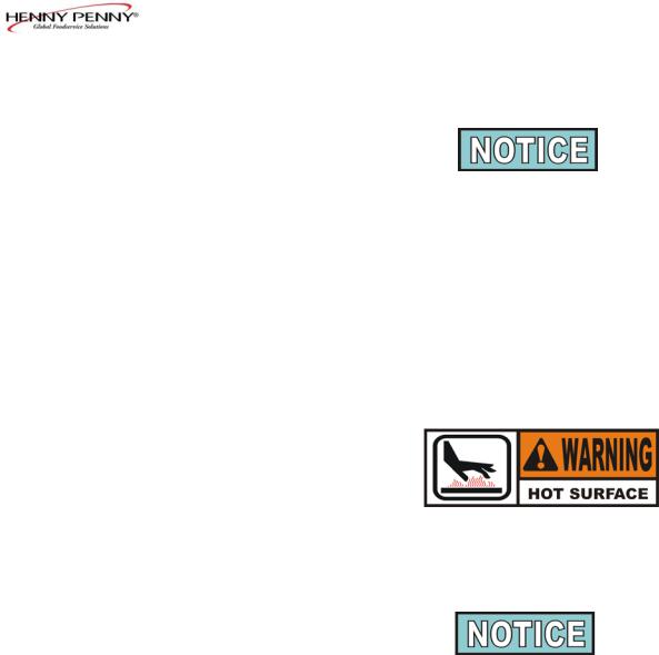
The SCR series rotisserie is a commercial appliance, and many surfaces could be hot. To prevent burns, it is recommended that the unit be located in an area that cannot be accessed by the public.
2-4. STACKING INSTRUCTIONS
A stacking kit must be used to stack rotisseries, or to stack a rotisserie on a display. This kit ensures 3 inches clearance from a rear wall. The part numbers of the stacking kits are 02664, for use on the SCR-6 and SCD-6, and 02665 is used on the SCR-8 and SCD-8.
See page 2-4 for single power cord installations.
1.Lay unit on its side and bolt locking casters or legs, to the control side of unit.
2.Using the bolts provided for the non-locking casters, or legs, bolt both the stacking spacer (provided in the kit) and the non-locking caster, or legs, to the front side of the unit. The stacking spacer should extend out the front of the unit about three inches.
3.Carefully lift the rotisserie and place it on top of the display, or bottom rotisserie, with the controls on the same side.
2-2 |
303 |

SCR-6/8
2-4. STACKING INSTRUCTIONS (Continued)
Take care when moving the unit to prevent personal injury. The SCR-8 weighs approximately 500 lbs. (230 kg) and the SCR-6 weighs 380 lbs. (172 kg).
4.Remove the three side panel screws from the top unit and remove the three top side panel side screws from the bottom unit.
5.Mount the stacking brackets to each side of the units, as shown in Figure 1, using the screws removed in step 4.
Figure 1
6.Unit is now ready for use.
For units being installed in Canada, for Price Costco, proceed with the following steps:
7.Remove the black plug button from the top of the upper unit.
8.Remove the screws from the channel assembly and take the top two parts apart.
9.Remove the screws along the corners of both top and bottom units.
10.Mount one side of the channel to the units, using the screws previously removed in step 9. See Figure 2.
11.Route the power cord up through the mounted channel and attach the cover to the channel, using the screws previously removed in step 8. See Figure 2.
12. Unit is now ready for use.
Figure 2
203 |
2-3 |
 Loading...