


OPERATOR’S
M A N U A L
OPEN FRYER (Electric)
MODEL
CFE-415
CFE-427
R E G I S T E R WA R R A N T Y O N L I N E AT W W W. H E N N Y P E N N Y. C O M
Original Instructions |
Read instructions before operating the appliance |

Model CFE-415, 427
|
|
TABLE OF CONTENTS |
|
Section |
|
|
Page |
Section 1. |
INTRODUCTION...................................................................................................... |
1 |
|
|
1-1 |
Safety............................................................................................................. |
1 |
|
1-2 |
Proper Care.................................................................................................... |
2 |
|
1-3 |
Assistance....................................................................................................... |
2 |
|
1-4 |
Introduction.................................................................................................... |
3 |
Section 2. |
INSTALLATION........................................................................................................ |
4 |
|
|
2-1 |
Introduction.................................................................................................... |
4 |
|
2-2 |
Unpacking...................................................................................................... |
4 |
|
2-3 |
Selecting the Fryer Location.......................................................................... |
5 |
|
2-4 |
Leveling the Fryer.......................................................................................... |
5 |
|
2-5 |
Ventilation of Fryer........................................................................................ |
6 |
|
2-6 |
Electrical Requirements ................................................................................ |
6 |
|
2-7 |
Dimensions..................................................................................................... |
8 |
Section 3. |
OPERATION.............................................................................................................. |
10 |
|
|
3-1 |
Operating Components.................................................................................. |
10 |
|
3-2 |
Clock Set........................................................................................................ |
14 |
|
3-3 |
Diagnostic Mode and Special Functions........................................................ |
16 |
|
3-4 |
Filling or Adding Oil...................................................................................... |
19 |
|
3-5 |
Filling Oil Reservoir...................................................................................... |
20 |
|
3-6 |
Basic Operations............................................................................................ |
21 |
|
3-7 |
Auto Top-Off ................................................................................................. |
23 |
|
3-8 |
Care of Shortening......................................................................................... |
24 |
|
3-9 |
Quick Filter ................................................................................................... |
25 |
|
3-10 |
Daily Filtering................................................................................................ |
27 |
|
3-11 |
Filter Menu..................................................................................................... |
29 |
|
3-12 |
Discarding Oil from Vat Using Optional Discard Shuttle.............................. |
30 |
|
3-13 |
Drain Pan Assembly....................................................................................... |
32 |
|
3-14 |
Clean-Out Mode............................................................................................. |
33 |
|
3-15 |
Check/Replace Filter Drain Pan O-Rings...................................................... |
36 |
|
3-16 |
Manually Setting New or Used Shortening................................................... |
37 |
|
3-17 |
Info Button Stats............................................................................................ |
38 |
|
3-18 |
Preventive Maintenance Schedule................................................................. |
39 |
Section 4. |
INFORMATION MODE............................................................................................. |
40 |
|
|
4-1 |
Information Mode Details.............................................................................. |
40 |
Section 5. |
TROUBLESHOOTING.............................................................................................. |
50 |
|
|
5-1 |
Introduction.................................................................................................... |
50 |
|
5-2 |
Troubleshooting............................................................................................. |
50 |
|
5-3 |
Warnings and Error Messages........................................................................ |
51 |
|
5-4 |
Troubleshooting Guide................................................................................... |
55 |
|
5-5 |
Diagnostic Mode Details................................................................................ |
61 |
April 2015 |
i |

HENNY PENNY
ELECTRIC OPEN FRYER
Fryer must be installed and used in such a way to prevent water from contacting the shortening.
This appliance is not intended to be operated by means of an external timer or a separate remote control system.
This appliance is not intended for use by persons (including children) with reduced physical, sensory or mental capabilities, or lack of experience and knowledge, unless they have been given supervision or instruction concerning use of the appliance by a person responsible for their safety.

|
Model CFE-415, 427 |
|
|
SECTION 1: INTRODUCTION |
|
1-1 |
The instructions in this manual have been prepared to aid you in learning |
|
SAFETY |
the proper procedures for your equipment. Where information is of |
|
|
particular importance or is safety related, the words NOTICE, CAUTION, |
|
|
or WARNING are used. Their usage is described below. |
|
|
If a problem occurs during the first operation of a new unit, recheck the |
|
|
Installation Section of the Operator’s Manual. |
|
|
Before troubleshooting, always recheck the Operation |
|
|
Section of the Operator’s Manual. |
|
|
Where information is of particular importance or is safety related, the |
|
|
words DANGER, WARNING, CAUTION, or NOTICE are used. Their |
|
|
usage is described as follows: |
|
|
SAFETY ALERT SYMBOL is used with DANGER, WARNING |
|
|
or CAUTION which indicates a personal injury type hazard. |
|
|
|
|
|
NOTICE is used to highlight especially important information. |
|
|
|
|
|
CAUTION used without the safety alert symbol indicates a |
|
|
potentially hazardous situation which, if not avoided, may result |
|
|
in property damage. |
|
|
|
|
|
CAUTION used with the safety alert symbol indicates a |
|
|
potentially hazardous situation which, if not avoided, could result |
|
|
in minor or moderate injury. |
|
|
|
|
|
WARNING indicates a potentially hazardous situation which, |
|
|
if not avoided, could result in death or serious injury. |
|
|
|
|
|
DANGER INDICATES AN IMMINENTLY |
|
|
HAZARDOUS SITUATION WHICH, IF NOT |
|
|
AVOIDED, WILL RESULT IN DEATH OR |
|
|
SERIOUS INJURY. |
|
March 2015 |
1 |
|
Model CFE-415, 427
1-1. SAFETY (CONT.)
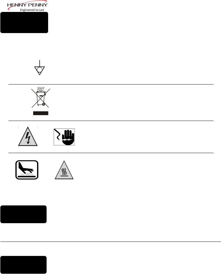
Equipotential Ground Symbol
Waste Electrical and Electronic Equipment (WEEE) Symbol
OR |
Shock Hazard Symbols |
OR
1-2. PROPER CARE
Hot Surface Symbols
As in all Henny Penny equipment, the unit requires care and maintenance. Requirements for maintenance and cleaning are contained in this manual and must be a regular part of the operation of the unit.
1-3. |
Should you require outside assistance, call your local distribu- |
tor in your area, or call 1-800-417-8405 or 1-937-456-8405.for |
|
ASSISTANCE |
Henny Penny Technical Support. |
March 2015 |
2 |

1-4 INTRODUCTION
March 2015
Model CFE-415, 427
The Henny Penny open fryer is a basic unit of food processing equipment designed to cook foods better and easier. The micro computer-based design helps make this possible. This unit is used only in institutional and commercial food service operations, and operated by qualified personnel.
The Chick-fil-Acontrols for the Henny Penny Models CFE-415 and
CFE-427 have many features to allow the Operator to produce consistent, quality product. The controls monitor not only cooking times and temperatures, but also shortening condition, product weights, product temperatures, and many other operational variables. The controls may vary the actual shortening temperature and cook times, based on changes of the operational variables.
The controls also have very extensive self-diagnostic functions which alert the Operator to both component and procedure problems.
Some unique features of the fryer are listed below:
•Diagnostic Function-provides summary of fryer and Operator performance; see Diagnostic Mode and Special Functions Section
•Alarms and Error Messages-provide immediate feedback for Operator error or fryer malfunction; see Warnings and Error Messages Section
•Status Mode-allows the Operator to view basic fryer information and status; see Diagnostic Mode and Special Functions Section
•Information Mode-gathers and stores historic information on the fryer and Operator performance, and can be viewed by the Operator; see Diagnostic Mode and Special Functions Section
•Manual Program Mode-Operator can set time and temperature for nonstandard products; see Diagnostic Mode and Special Functions Section
•Easy toggle between English and Spanish operation. See Diagnostic Mode and Special Functions Section
•Clean-Out Mode-a preprogrammed function for cleaning the frypot; see Cleaning the Frypot Section
3
Model CFE-415, 427
SECTION 2: INSTALLATION
2-1 |
This section provides the installation and unpacking instructions for the |
INTRODUCTION |
Henny Penny fryer. |
|
Installation of this unit should be performed only by a qualified service technician.
Do not puncture the fryer with any objects such as drills or screws as component damage or electrical shock could result.
2-2
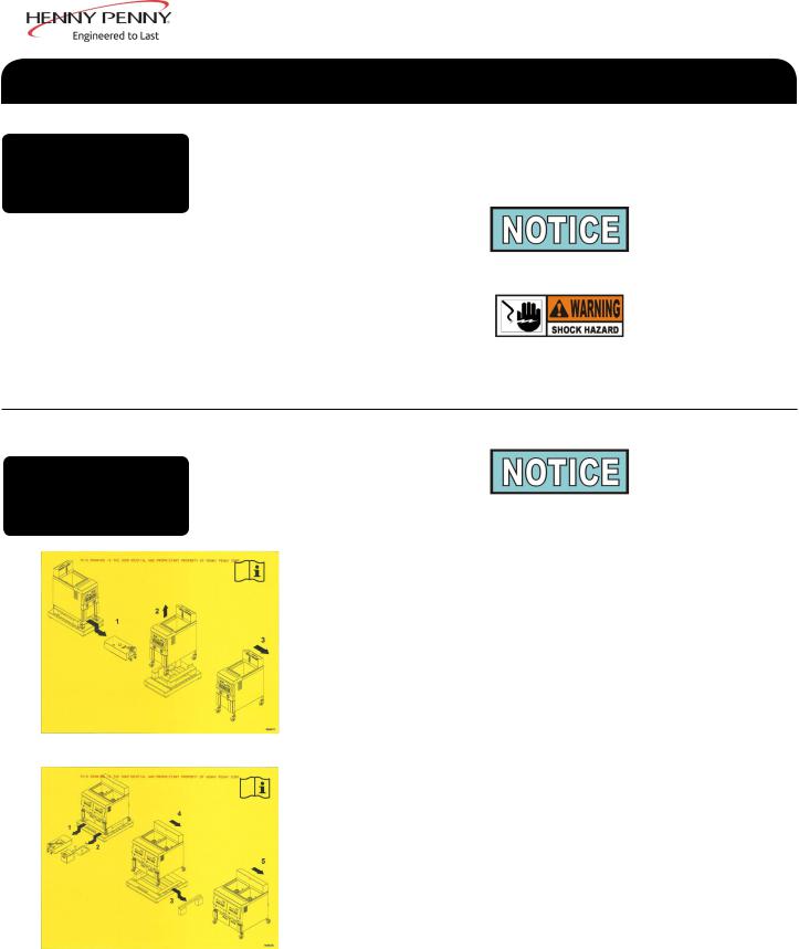
UNPACKING Any shipping damage should be noted in the presence of the delivery agent and signed prior to his or her departure.
1.Carefully cut and remove banding straps.
2.Lift the main box off the fryer. (This procedure should be performed in an area with high ceilings, to avoid damage to the unit and ensure sufficient clearance.
3.Unlatch and remove the drain pan from underneath fryer. Place in a location clear of unpacking area.
4.Cut and remove plastic banding strap from around the fryer that is laced through the pallet build-ups.
5.Tilt the fryer to one side and knock off the build-up free of fryer. This will take two individuals, one for the tilting and second one to remove build-up.
6.Once build-up is removed, relax fryer on pallet. Carefully push fryer sideways in the direction of the removed build-up to clear the second build-up.
Feb. 2016 |
4 |
2-2 UNPACKING (CONT.)
Model CFE-415, 427
7.Continue to slowly push fryer in the same sideways direction. Make sure the casters are all rolling on the pallet deck board surfaces. Do not allow casters to drop between pallet surface spaces. Ease fryer off the pallet edge and clear of pallet.
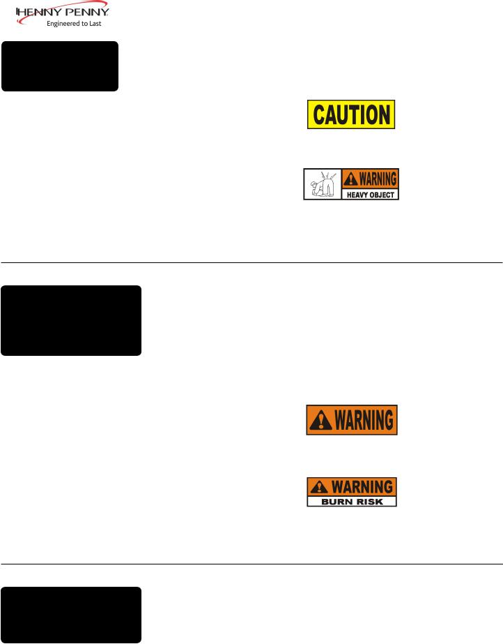
Remove filter drain pan from fryer before removing fryer from pallet or damage to the unit could result. Figure 1.
Take care when moving the fryer to prevent personal injury. The CFE415 weighs about 280 lbs. and the CFE-427 about 400 lbs.
2-3 SELECTING THE FRYER
LOCATION
The proper location of the fryer is very important for operation, speed, and convenience. The location of the open fryer should allow clearances for servicing and proper operation. Choose a location which will provide easy loading and unloading without interfering with the final assembly of food orders. Operators have found that frying from raw to finish, and holding the product in warmers provides fast continuous service. Keep in mind, the best efficiency will be obtained by a straight line operation, i.e. raw in one side and finished out the other side. Order assembly can be moved away with only a slight loss of efficiency.
To avoid fire and ruined supplies, the area under the fryer should not be used to store supplies.
To prevent severe burns from splashing hot oil, position and install fryer to prevent tipping or movement. Restraining ties may be used for stabilization.
|
For proper operation, the open fryer should be level from side-to-side and |
|
2-4 |
front to back. Using a level placed on the flat areas around the vat collar, |
|
on the middle well, and then adjust the casters until the unit is level. |
||
LEVELING THE FRYER |
||
|
March 2015 |
5 |
2-5 VENTILATION OF FRYER
Model CFE-415, 427
The fryer should be located with provision for venting into an adequate exhaust hood or ventilation system. This is essential to permit efficient removal of the steam exhaust and frying odors. Special precaution must be taken in designing an exhaust canopy to avoid interference with the operation of the fryer. We recommend you consult a local ventilation or heating company to help in designing an adequate system.
Ventilation must conform to local, state, and national codes. Consult your local fire department or building authorities.
2-6 |
Check the data plate, mounted on the left-hand side of shroud for 427 |
or the right-hand side of shroud for 415, to determine the correct power |
|
ELECTRICAL |
supply. |
REQUIREMENTS |
|
|
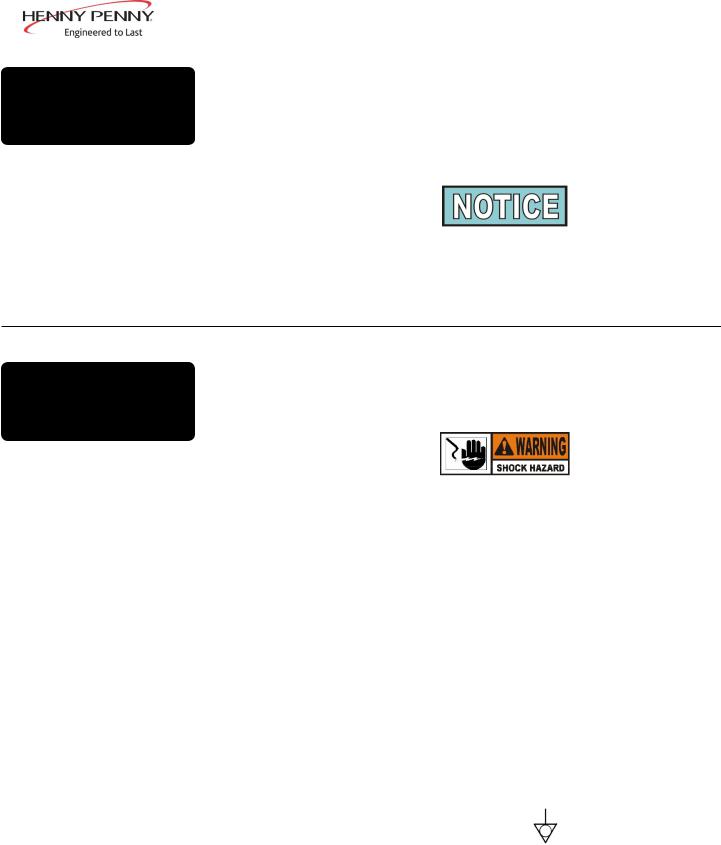
To avoid electrical shock, do not disconnect the ground (earth) plug. |
|
This fryer must be adequately and safely grounded (earthed). Refer to |
|
local electrical codes for correct grounding (earthing) procedures or in |
|
absence of local codes, with The National Electrical Code, ANSI/NFPA |
|
No. 70-(the current edition). In Canada, all electrical connections are to |
|
be made in accordance with CSA C22.2, Canadian Electrical Code Part 1, |
|
and or local codes. |
|
To avoid electrical shock, this appliance must be equipped with an |
|
external circuit breaker which will disconnect all ungrounded (unearthed) |
|
conductors. The main power switch on this appliance does not |
|
disconnect all line conductors. |
|
(FOR EQUIPMENT WITH CE MARK ONLY!) |
|
To prevent electric shock hazard, this appliance must be bonded to |
|
other appliances or touchable metal surfaces in close proximity to this |
|
appliance with an equipotential bonding conductor. This appliance is |
|
equipped with an equipotential lug for this purpose. The equipotential |
|
lug is marked with the following symbol. |
April 2015 |
6 |
2-6 ELECTRICAL REQUIREMENTS (CONT.)
DRYWALL CONSTRUCTION Secure I-bolt to a building stud. Do not attach to drywall only. Preferred installation is approximately six inches to either side of service. Cable restraint must be at least six inches shorter than flexible conduit.
Model CFE-415, 427
An all pole, separate disconnect switch, with proper capacity fuses or breakers must be installed at a convenient location between the fryer and the power source, and must be installed according to national and local codes. It should be an insulated copper conductor rated for 600 volts and 90° C. For runs longer than 50 feet (15.24 m), use the next larger wire size. CE units require a minimum wire size of 6 mm to be wired to the terminal block.
It is recommended that a 30 mA rated protective device such as a residual current circuit breaker (RCCB), or ground fault circuit interrupter (GFCI), be used on the fryer circuit.
Permanently connected electric fryers with casters must be installed with flexible conduit and a cable restraint, when installed in the United
States. See illustration at left. Holes are available in the rear fryer frame for securing the cable restraint to the fryer. The cable restraint does not prevent the fryer from tipping.
The supply power cords shall be oil-resistant, sheathed flexible cable, no lighter than ordinary polychloroprene or other equivalent synthetic elastomer-sheathed cord.
March 2015 |
7 |
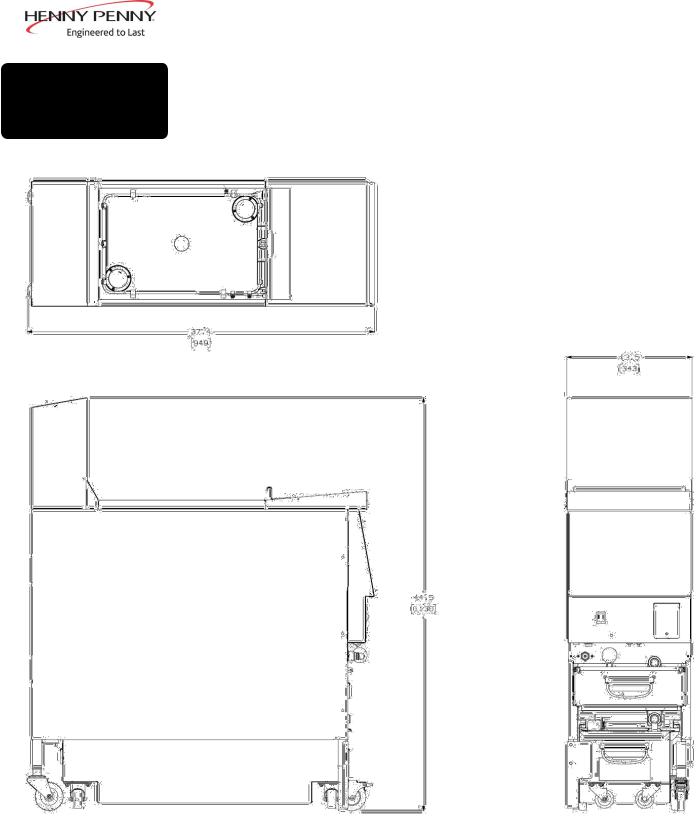
Model CFE-415, 427
2-7 DIMENSIONS
CFE-415
Feb. 2016 |
8 |
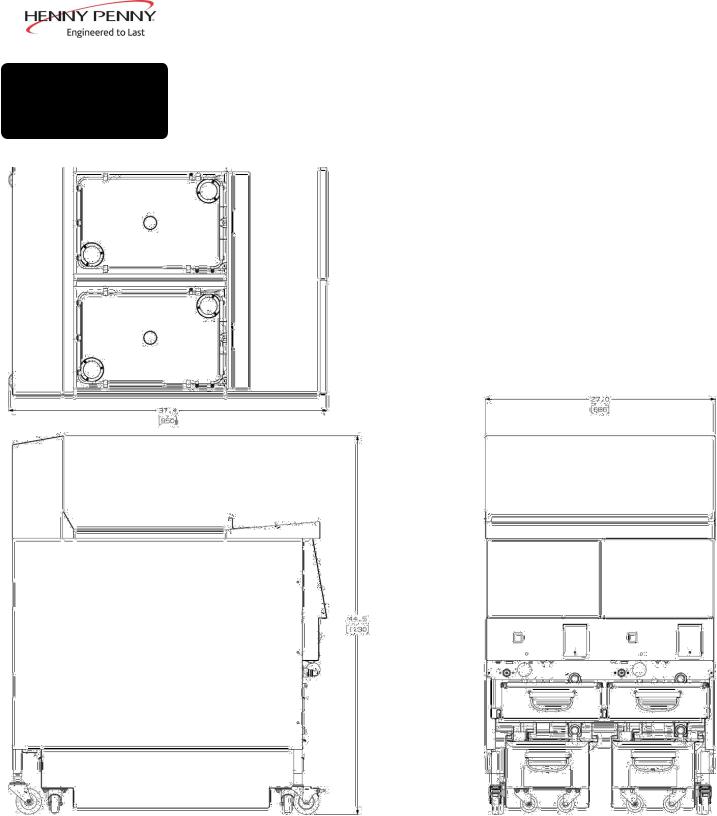
Model CFE-415, 427
2-7 DIMENSIONS (CONT.)
CFE-427
Feb. 2016 |
9 |

Model CFE-415, 427
SECTION 3: OPERATION
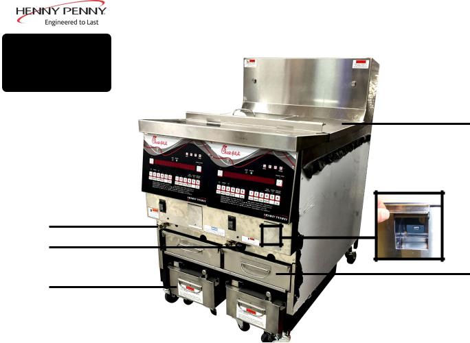
3-1 |
|
|
|
Refer to explanations on the next pages. |
|
|
|
|
|
|
|
|
|
OPERATING |
|
|
|
|
|
|
COMPONENTS |
|
|
|
|
|
|
2 |
1 |
3 |
4 |
5 |
6 |
7 |
8 |
9 |
10 |
8 |
|
|
Figure 3-1 |
|
12
11
Figure 3-2 |
Figure 3-3 |
|
March 2015 |
10 |
|
|
|
Model CFE-415, 427 |
|
|
3-1 |
|
Refer to Figures 3-1, 3-2 & 3-3 in conjunction with the description of |
|
OPERATING |
|
the functions below. |
||
|
|
|||
COMPONENTS |
|
|||
|
(CONT.) |
|
|
|
|
|
|
|
|
Fig. |
Item |
Description |
Function |
|
No. |
||||
|
|
|
||
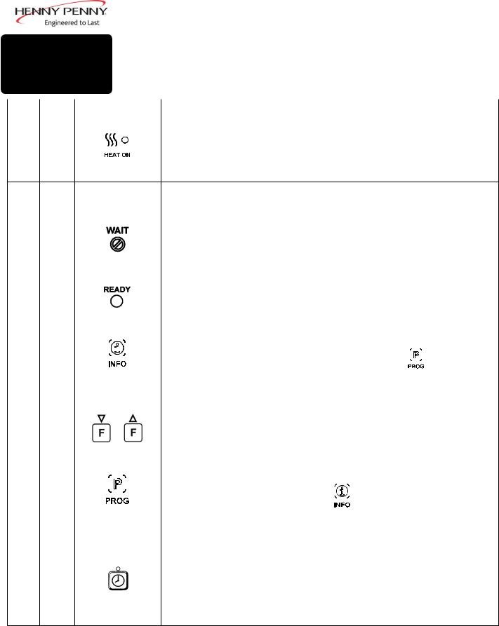
3-1 |
1 |
|
Lights when the control calls for heat and the shortening should start heating |
|
3-1 |
2 |
Digital Display Shows all the functions of the Cook Cycle, Program Mode, Diagnostic Mode |
|||||||||||||||||||
|
|
|
|
|
|
|
|
|
and alarms |
|
|
|
|
|
|
|
|||||
|
|
|
|
|
|
|
|
|
|
|
|
|
|
|
|
|
|
|
|
|
|
3-1 |
3 |
|
|
|
|
|
|
|
Flashes when the shortening temperature is not at the proper temperature for |
||||||||||||
|
|
|
|
|
|
|
|
|
dropping product into the frypot |
|
|
|
|
|
|
|
|||||
|
|
|
|
|
|
|
|
|
|
|
|
|
|
|
|
|
|
|
|
|
|
3-1 |
4 |
|
|
|
|
|
|
|
Lights when the shortening temperature is 5°F below setpoint to 15°F above |
||||||||||||
|
|
|
|
|
|
|
|
|
setpoint, signaling product can now be cooked |
|
|
||||||||||
|
|
|
|
|
|
|
|
|
|
|
|
|
|
|
|
|
|
|
|
|
|
3-1 |
5 |
|
|
|
|
|
|
|
Press to display current fryer information and status; if pressed in the Program |
||||||||||||
|
|
|
|
|
|||||||||||||||||
|
|
|
|
|
|
|
|||||||||||||||
|
|
|
|
|
|
|
|
|
Mode, it shows previous settings; pressing this along with |
|
|
|
|
|
accesses the |
||||||
|
|
|
|
|
|
|
|
|
|
|
|
|
|
||||||||
|
|
|
|
|
|
|
|
|
|
|
|||||||||||
|
|
|
|
|
|
|
|
|
Information Mode which has historic information on the Operator and fryer |
||||||||||||
|
|
|
|
|
|
|
|
|
performance |
|
|
|
|
|
|
|
|||||
|
|
|
|
|
|
|
|
|
|
|
|
|
|
|
|
|
|
|
|
|
|
3-1 |
6 |
|
|
|
|
|
|
|
Used to access the Filter Menu; also used for ▲ or ▼buttons |
|
|
||||||||||
|
|
|
|
|
|
|
|
|
|
|
|
|
|
|
|
|
|
|
|
|
|
3-1 |
7 |
|
|
|
|
|
|
|
Press to access Program Mode; once in the Program Mode, it is used to advance |
||||||||||||
|
|
|
|
|
|
|
|||||||||||||||
|
|
|
|
|
|
|
|||||||||||||||
|
|
|
|
|
|
|
|
|
|
|
|
|
|
|
it accesses the Information Mode |
||||||
|
|
|
|
|
|
|
|
|
|
|
|
|
|
|
|||||||
|
|
|
|
|
|
|
|
|
to the next setting; if pressed along with |
|
|
|
|
||||||||
|
|
|
|
|
|
|
|
|
which has historic information on the Operator and fryer performance; it also |
||||||||||||
|
|
|
|
|
|
|
|
|
allows access to the English-Spanish settings, diagnostics, Clean-Out Mode, |
||||||||||||
|
|
|
|
|
|
|
|
|
and Manual Mode, if pressed before the appropriate button |
|
|
||||||||||
|
|
|
|
|
|
|
|
|
|
|
|
|
|
|
|
|
|
|
|
|
|
3-1 |
8 |
|
|
|
|
|
|
|
Used to stop Cook Cycles and to stop the timer at the end of a Hold Cycle; it is |
||||||||||||
|
|
|
|
|
|
|
|
|
also used to program a Manual Program for nonstandard products |
||||||||||||
April 2015 |
11 |
Model CFE-415, 427
3-1 OPERATING COMPONENTS (CONT.)
Fig. |
Item |
Description |
|
Function |
|
|
|
No. |
|
|
|
|
|||
|
|
|
|
|
|
|
|
3-1 |
9 |
Menu Card |
Shows name of food product selected; the menu card strip is located behind the |
||||
|
|
|
decal |
|
|
|
|
|
|
|
|
|
|||
3-1 |
10 |
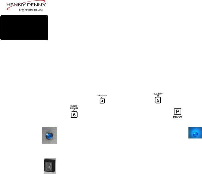
Product Select |
Press to select food products to be cooked, as well as, answering display |
|
|||
|
|
Button |
|
|
|
|
|
|
|
|
prompts; also, |
accesses the diagnostics; |
, the Clean-Out Mode; and |
||
|
|
|
toggles between English and Spanish display (Press |
before entering |
|||
|
|
|
any of the above modes.) |
|
|
|
|
3-2 |
11 |
|
|
|
|
|
|
|
|
|
A Filter Light is found beside each black drain knob; when lit blue |
, |
|||
|
|
|
indicates the oil should be filtered at this time; |
beacon flashes when the drain |
|||
|
|
|
needs opened or closed |
|
|
|
|
|
|
|
|
||||
3-3 |
12 |
|
When the power switch is turned to the ON position, power is supplied to the |
||||
|
|
|
controls and pumps |
|
|
|
|
|
|
|
|
|
|
|
|
April 2015 |
12 |
Model CFE-415, 427
3-1 OPERATING COMPONENTS (CONT.)
4
5
2
3
6
1
|
|
|
Figure 3-4 |
Fig. |
Item |
Description |
Function |
No. |
No. |
|
|
3-4 |
1 |
Filter Drain Pan Assy. |
Oil is drained into this pan and then is pumped |
|
|
|
through filters to help prolong the use of the oil |
3-4 |
2 |
Quick Disconnect |
Connection for oil disposal shuttle |
3-4 |
3 |
Drain Valve Knob |
Pull-out on black knobs to open drain valve and oil |
|
|
|
drains from vat; Push-in to close drain valve and oil can |
|
|
|
be pumped into vat |
3-4 |
4 |
Vat Covers |
Covers the vat when not in use |
3-4 |
5 |
USB Port |
Used to download information from controls & perform |
|
|
|
firmware updates |
3-4 |
6 |
ATO (Auto top Off) |
Used to hold oil for the automatic oil top-off feature; |
|
|
|
should be filled once a day |
3-4 |
7* |
1/2 basket |
Each frypot accommodates two 1/2 baskets or one full- |
|
|
|
size nugget or tier basket |
*Not Shown |
|
|
|
March 2016 |
|
13 |
|

3-2 CLOCK SET
March 2015
Model CFE-415, 427
Upon initial start-up or PC board replacement, if “CLOCK SET” automatically appears in the display, skip steps 1, 2 and 3.
1.1. Press and hold  for 5 seconds until “LEVEL 2” shows in display.
2.Release  , then press
  twice. “CLOCK SET” then “ENTER CODE” shows in display.
3.Press  .
.
4.Display shows “CS-1” then “SET” then “MONTH”, with the month flashing.
5. Press |
|
|
|
|
|
|
|
|
|
|
|
|
to change the month. |
|
|
|
|
||||||||||
|
|
|
|
||||||||||
|
|
|
|
|
|
|
|
|
|
|
|
|
|
6.Press  . Display shows “CS-2” then “SET” then “DATE”, with the date flashing.
7. Press |
|
|
|
|
|
|
|
|
|
|
|
|
to change the date. |
|
|
|
|
||||||||||
|
|
|
|
||||||||||
|
|
|
|
|
|
|
|
|
|
|
|
|
|
8.Press  . Display shows “CS-3” then “SET” then “YEAR”, with the year flashing.
9. Press |
|
|
|
|
|
|
|
|
|
|
|
|
to change the year. |
|
|
|
|
||||||||||
|
|
|
|
||||||||||
|
|
|
|
|
|
|
|
|
|
|
|
|
|
10.Press  . Display shows “CS-4” then “SET” then “HOUR”, with the hour and “AM” or “PM” flashing.
11. Press |
|
|
|
|
|
|
|
|
to change the hour and AM/PM setting. |
|
|
|
|
|
|
|
|
||
|
|
|
|
|
|
|
|||
|
|
|
|
|
|
|
|
|
|
12.Press  . Display shows “CS-5” then “SET” then “MINUTE”, with the minutes flashing.
13. Press |
|
|
|
|
|
|
|
to change the minutes. |
|
|
|
|
|
|
|
||
|
|
|
|
|
|
14

3-2 CLOCK SET (CONT.)
March 2015
Model CFE-415, 427
14.Press  . Display shows “CS-6” then “CLOCK MODE”, along with “1.AM/PM”.
15.“1.AM/PM” is 12 hour time, “2.24-HR” is 24 hour time.
Press |
|
|
|
|
|
|
|
|
|
|
|
|
to change. |
|
|
|
|
||||||||||
|
|
|
|||||||||||
|
|
|
|
|
|
|
|
|
|
|
|
|
|
16.Press  . Display shows “CS-7” then “DAYLIGHT SAVINGS ADJ”, along with “2.US”.
17. Press |
|
|
|
|
|
|
|
|
|
|
|
to change to the following: |
|
|
|
|
|||||||||
|
|
|
a. “1.OFF” = No automatic adjustments for Daylight Savings Time.
b.“2.US” = Automatically applies United States Daylight
Savings Time adjustment. DST activated on the first Sunday in
April. DST de-activated on the last Sunday in October.
c.“3.EURO” = Automatically applies European (CE) Daylight Savings Time adjustment. DST activated on the last Sunday in March. DST de-activated on the last Sunday in October.
d.“4.FSA” = First Sunday in April (this is the old U.S. DST).
18.Clock Set is now complete. Press and hold  to exit.
15

3-3 DIAGNOSTIC MODE
AND SPECIAL
FUNCTIONS
March 2015
Model CFE-415, 427
Diagnostic Mode
To view summaries of the fryer and Operator performance,
|
|
|
|
|
|
|
|
|
|
|
|
|
|
|
|
|
|
|
|
|
|
|
|
|
|
|
|
|
|
press |
|
|
|
then |
. Press |
|
|
|
|
|
|
|
to view the following |
|
|
|
|
|
|
|
|
|
|
|
|||||
|
|
|
|
|
||||||||||
functions: |
|
|
|
|
|
|
|
|
|
|
||||
•D1 - Adjust product color for all products (not individually)
•D2 - The age of the shortening and life remaining
•D3 - Outlet voltage monitoring
•D4 - Fryer’s heating performance
•D5 - Cook Times Today
•D6 -Cooked Before Ready
•D7 - Cook Cycles stopped more than 10 seconds before end of cycle
•D8 - Cook Cycles not ended within 20 seconds after expired time
•D9 - Number of times loading product took too long
•D10 -Programmed variables changed by Operator
On several of the screens you may have to press  or
or  to respond to questions asked.
Press  at any time to exit and return to normal operation.
See Diagnostic Mode Details Section for more details of the Diagnostic Mode.
Language Selection
Pressing  then
then  allows the Operator to choose to display the information in English or Spanish.
16
3-3 DIAGNOSTIC MODE
AND SPECIAL
FUNCTIONS (CONT.)
March 2015
Model CFE-415, 427
Manual Mode
This allows the Operator to quickly program a time and press temperature for nonstandard products that are not on the menu card. This is to be a temporary setting and disables most of the advanced features of the controls. To enter
Manual Mode: |
|
|
|
|
|
|
|
|
|
|
|
|
|
|
|
|
|
|
|
|||||||||||
|
|
|
|
|
|
|
|
|
|
|
|
|
|
|
|
|
|
|
|
|
|
|
|
|
|
|
|
|
|
|
|
|
|
|
|
|
|
|
|
|
|
|
|
|
|
|
|
|
|
|
|
|
|
|
|
|
|
|
|
|
|
1. |
Once out of the Melt Cycle, press |
|
|
then |
. |
|||||||||||||||||||||||||
|
|
|||||||||||||||||||||||||||||
2. |
Use |
|
|
|
|
|
|
|
|
|
|
|
|
|
to set cook time. |
|
|
|
|
|||||||||||
|
|
|
|
|
|
|
|
|
|
|
|
|
|
|
|
|
|
|
||||||||||||
|
|
|
|
|
|
|
|
|||||||||||||||||||||||
|
|
|
|
|
|
|
|
|
|
|
|
|||||||||||||||||||
|
|
|
|
|
|
|
|
|
|
|
|
|
|
|
|
|||||||||||||||
|
|
|
|
|
|
|
|
|
|
|
|
|
||||||||||||||||||
|
|
|
|
|
|
|
|
|
|
|
|
|
|
|
|
|
|
|
|
|
|
|
|
|
|
|
|
|
|
|
|
|
|
|
|
|
|
|
|
|
|
|
|
|
|
|
|
|
|
|
|
|
|
|
|
|
|
|
|
|
|
|
|
|
|
|
|
|
|
|
|
|
|
|
||||||||||||||||||
3. |
Press |
|
|
|
|
|
|
and use |
|
|
|
|
|
|
|
to set temperature. |
|
|||||||||||||
|
|
|
|
|
|
|
|
|
|
|||||||||||||||||||||
|
|
|
|
|
|
|
|
|
|
|
|
|
|
|
|
|
|
|
|
|
|
|
|
|
|
|
|
|
|
|
4.Press  to start Manual Mode. Display shows. “MANUAL” and you start a Cook Cycle by pressing
  .
.
5.Press  to exit Manual Mode.
Status Mode
Pressing  during idle time, allows Operator to view:
a.The temperature of the shortening
b.The temperature setpoint and any offset
c.The average shortening temperature during last Cook Cycle
d.The rate of temperature rise or fall
e.Date and Time
Pressing  during a Cook Cycle allows the Operator to view:
a.The temperature of shortening, plus the degrees and rate the load compensation has affected the Cook Cycle (slows down or speeds up the timer)
b.The cooking step, the time left in Cook Cycle, and setpoint temperature
c.Average shortening temperature in Cook Cycle so far
d.The rate of temperature rise or fall
e.Date and Time
After 5 seconds, the control exits the Status Mode and the open fryer returns to normal operation.
17

3-3 DIAGNOSTIC MODE
AND SPECIAL
FUNCTIONS (CONT.)
March 2015
Model CFE-415, 427
Information Mode
This mode gathers and stores historic information on the fryer and
Operator performance. Press  and
and  at the same time and
“*INFO MODE*” shows on display. Press  or
or  to access
the steps and press  to view the statistics within each step.
Information Mode is intended for technical use, but the Operator can view the following information:
1.E-LOG - last 10 errors and time they occurred
2.P-LOG - time of last 10 power-ups
3.HEAT-UPS - time of day and maximum heating rate (°/second) for the last 10 heat-ups
4.LEFT COOK DATA - information on the last Cook Cycle, using the left timer button
5.RIGHT COOK DATA - information on the last Cook Cycle, using the right timer button
6.TODAY’S DATA - data since the start of day (not including the last Cook Cycle)
7.PREV-DAY-SUN - creates a log of the last 7 days, using the information in TODAY’S DATA.
8.7-DAY TOTALS-totals the information from the last 7days
9.OIL DATA - information on the current shortening, not including today’s cooking information
10.PREV OIL DATA - information on last batch of shortening
11.INP - provides test of fryer inputs
12.OUTP - shows the state of heater
13.POT TMP - temperature of shortening
14.CPU TMP - temperature of PC board
15.ANALOG - status of controller’s a-to-d converter
16.AC VOLTS - status of the line voltage to fryer
17.AMPS (Electric models only) - the present amp readings to heaters.
See Information Mode Details Section for more details.
18

3-4 FILLING OR ADDING OIL
Figure 1
March 2015
Model CFE-415, 427
The oil level must always be above the heater elements when fryer is heating and at the oil level indicators on the rear of vat. Failure to follow these instructions could result in a fire and/or damage to the fryer.
Solid oil is not recommended. Solid oil could cause clogging and pump failures.
Wear gloves to avoid severe burns when pouring hot oil into vat. Oil and all metal parts that are in contact with the oil are extremely hot; take care to avoid splashing.
1.It is recommended that a high quality frying oil be used in the open fryer. Some low grade oils have a high moisture content and cause foaming and boiling over.
2.Oil Capacity: 48 lbs/vat
All vats have 2 level indicator lines inscribed on the rear wall of the vat. The upper-most line shows the oil at the proper level when
heated. The lower line shows oil at the proper level at room temperature. Figure 1.
19
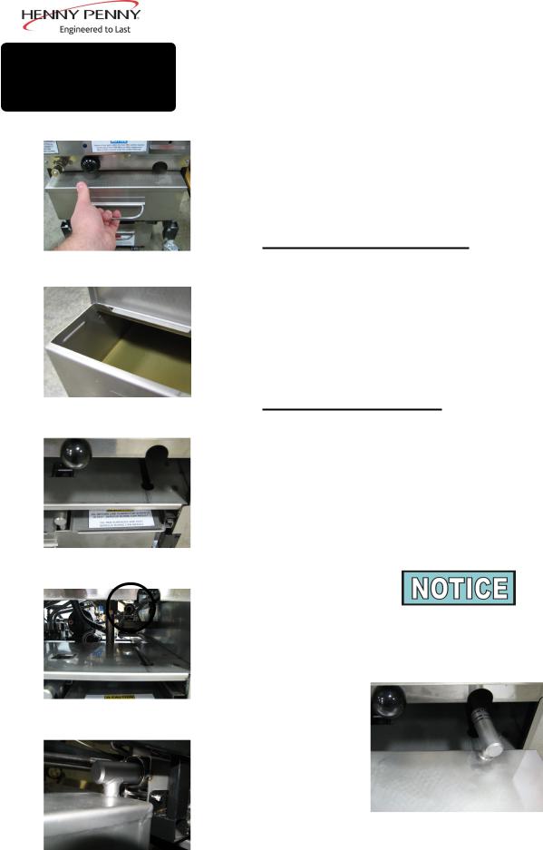
3-5
FILLING OIL RESERVOIR
Figure 1
Figure 2
Figure 3
Figure 4
Figure 5
March 2016
Model CFE-415, 427
1.During morning start-up procedures when control displays “FILL RESERVE OIL” or when control displays “E-1” and an alarm sounds, fill the auto-fill oil reservoir.
2.Pull reservoir forward and open reservoir cover. See Figure 1.
3.Pour oil into reservoir, then close cover and push reservoir back into position. See Figure 2.
Removing/Cleaning Reservoir
1.Pull reservoir forward until it stops.
2.Lift-up on reservoir, disengaging the reservoir from the slotted keyway. Figure 3.
3.Clean reservoir at a sink with soap and water.
Reinstalling the Reservoir
1.Place the oil reservoir onto the shelf. Be sure to align the studs on the bottom of the reservoir to the slots in the shelf. See Figure 3.
2.Push the reservoir back until it the tube is aligned with the receiver. See Figure 4.
3.Push the reservoir into the receiver until it is fully engaged (all 3 o-rings are inserted into the receiver). See Figure 5.
Before placing the reservoir back into position, lubricate the o-rings
(below) on the filter tube with cold oil. Check o-rings for tears or nicks and replace if necessary. To replace o-ring, use a small, flat-bladed screwdriver, pry up on the o-ring and pull off of end of tube. See below.
20

3-6
BASIC OPERATIONS
March 2015
Model CFE-415, 427
1.Fill the oil reservoir. See Section 3-5.
2.Turn the POWER switch to ON. Upon initial start-up “CLOCK SET” may show in display. Set the clock to your time, following prompts on the display, or see Section 3-2 for help. Then display asks if the shortening is “NEW” or “OLD”. The controls automatically adjust the shortening temperature to the age of
the shortening. Use |
|
|
|
|
|
|
|
|
|
|
|
to set the number of days of old |
|
|
|
|
|||||||||
|
|
|
||||||||||
shortening. |
|
|
|
|
|
|
|
|
||||
Unit automatically goes into the Melt Cycle until the oil temperature reaches 230°F (110°C). The controls go into the Heat Cycle and the shortening heats to a preset temperature after reaching 230°F.
Do not leave fryer unattended unless enough oil has melted to completely cover all of the elements.
3.Once out of the Melt Cycle,  flashes until 5° before setpoint temperature (plus any offset temperature).
4.Stir the shortening when prompted to “STIR VAT”. Be sure to stir down into the bottom of the vat and back up to throughly mix the oil from bottom to top.
5.Once the controls detect a stir, the timer will count down. Continue stirring during this time.
6.Unit will return to flashing “WAIT”. (If it prompts to “STIR
VAT” additional times, continue stirring until the prompt disappears.) When vat has cooled to cooking temperature,  then lights and the selected product shows on display.
The heat cycles on and off near the setpoint temperature to help prevent overshooting the setpoint temperature (proportional control).
21
 Loading...