


OPERATOR’S
M A N U A L
VELOCITY SERIESTM PRESSURE FRYER
MODEL
PXE-100
R E G I S T E R WA R R A N T Y O N L I N E AT W W W. H E N N Y P E N N Y. C O M
Original Instructions |
Read instructions before operating the appliance |
HENNY PENNY
ELECTRIC PRESSURE FRYER
SPECIFICATIONS |
|
Pot Capacity |
8 head of chicken - 24 lbs. (10.8 kg) |
|
76 lbs. oil (34 Kg.) |
Electrical |
208 VAC, 3 Phase, 50/60 Hz, 17 KW, 47.2 Amps |
|
240 VAC, 3 Phase, 50/60 Hz, 17 KW, 40.9 Amps |
|
480 VAC, 3 Phase, 50/60 Hz, 17 KW, 20.5 Amps |
Heating |
Two 8,500 watt electric immersion elements |
Adata plate, located on the back shroud behind the lid identifies the fryer model, serial number, warranty date, and other information. Also, the serial number is stamped on the outside of the counter top. See figure below.
Serial No.
PXE-100
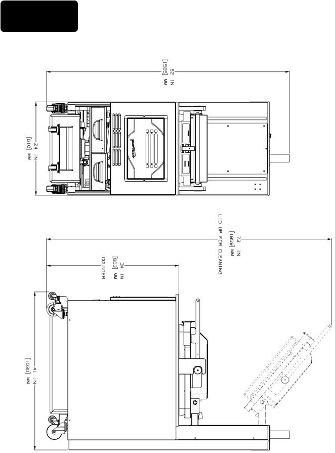
DIMENSIONS

HENNY PENNY
8 HEAD ELECTRIC PRESSURE FRYER
Fryer must be installed and used in such a way to prevent water from contacting the shortening.
This appliance is not intended to be operated by means of an external timer or a separate remote control system.
This appliance is not intended for use by persons (including children) with reduced physical, sensory or mental capabilities, or lack of experience and knowledge, unless they have been given supervision or instruction concerning use of the appliance by a person responsible for their safety.

|
|
TABLE OF CONTENTS |
|
Section |
|
|
Page |
Section 1. |
INTRODUCTION...................................................................................................... |
1 |
|
|
1-1 |
Safety............................................................................................................. |
1 |
|
1-2 |
Proper Care.................................................................................................... |
2 |
|
1-3 |
Assistance....................................................................................................... |
2 |
Section 2. |
INSTALLATION........................................................................................................ |
3 |
|
|
2-1 |
Introduction.................................................................................................... |
3 |
|
2-2 |
Unpacking...................................................................................................... |
3 |
|
2-3 |
Selecting the Fryer Location.......................................................................... |
7 |
|
2-4 |
Leveling the Fryer.......................................................................................... |
7 |
|
2-5 |
Ventilation of Fryer........................................................................................ |
8 |
|
2-6 |
Electrical Requirements................................................................................. |
8 |
|
2-7 |
International Electrical Requirements............................................................ |
9 |
Section 3. |
OPERATION.............................................................................................................. |
11 |
|
|
3-1 |
Operating Components.................................................................................. |
11 |
|
3-2 |
Control Overview........................................................................................... |
12 |
|
3-3 |
Display Options.............................................................................................. |
14 |
|
3-4 |
4+Title Option................................................................................................ |
14 |
|
3-5 |
5+Next Option................................................................................................ |
15 |
|
3-6 |
6 Item Option................................................................................................. |
15 |
|
3-7 |
Drain Pan Assembly....................................................................................... |
16 |
|
3-8 |
Product Racking Recommendations.............................................................. |
17 |
|
3-9 |
Lid Operation................................................................................................. |
18 |
|
3-10 |
Start-up........................................................................................................... |
20 |
|
3-11 |
Filling the Oil Tank........................................................................................ |
21 |
|
3-12 |
Condensation Tank......................................................................................... |
21 |
|
3-13 |
Filter Pump Motor Protector-Manual Reset................................................... |
22 |
|
3-14 |
Regular Maintenance Schedule...................................................................... |
22 |
|
3-15 |
Initial Oil Fill................................................................................................. |
23 |
|
3-16 |
Basic Operation.............................................................................................. |
24 |
|
3-17 |
Care of the Oil................................................................................................ |
25 |
|
3-18 |
Main Menu..................................................................................................... |
25 |
|
3-19 |
Filtering Instructions...................................................................................... |
26 |
|
3-20 |
Bulk Dispose.................................................................................................. |
30 |
|
3-21 |
Changing the Filter Envelope........................................................................ |
31 |
|
3-22 |
Clean-Out Mode............................................................................................. |
31 |
|
3-23 |
Preventive Maintenance ................................................................................ |
36 |
Section 4. |
PROGRAMMING........................................................................................................ |
39 |
|
|
4-1 |
Program Menu................................................................................................ |
39 |
|
4-2 |
Product Programming.................................................................................... |
39 |
|
4-3 |
Special Programming..................................................................................... |
41 |
Section 5. |
TROUBLE SHOOTING................................................................................................ |
44 |
|
|
5-1 |
Troubleshooting Guide................................................................................... |
44 |
|
5-2 |
Error Codes.................................................................................................... |
45 |
Sept. 2014
SECTION 1: INTRODUCTION
1-1 |
The instructions in this manual have been prepared to aid you in learning |
SAFETY |
the proper procedures for your equipment. Where information is of |
|
particular importance or is safety related, the words NOTICE, CAUTION, |
|
or WARNING are used. Their usage is described below. |
|
If a problem occurs during the first operation of a new unit, recheck the |
|
Installation Section of the Operator’s Manual. |
|
Before troubleshooting, always recheck the Operation |
|
Section of the Operator’s Manual. |
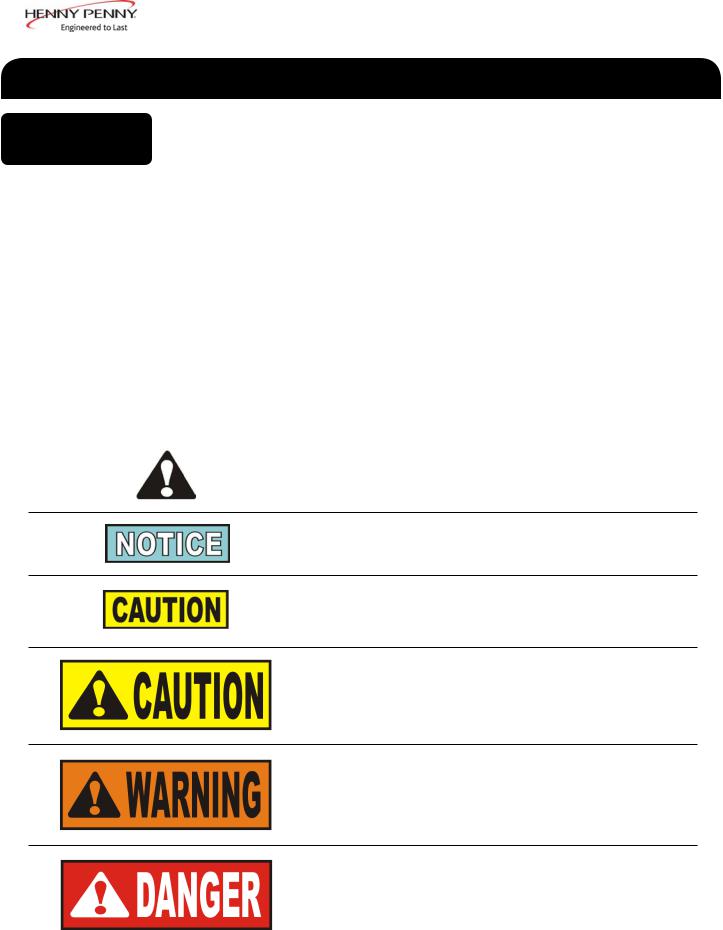
Where information is of particular importance or is safety related, the words DANGER, WARNING, CAUTION, or NOTICE are used. Their
usage is described as follows:
SAFETY ALERT SYMBOL is used with DANGER, WARNING or CAUTION which indicates a personal injury type hazard.
NOTICE is used to highlight especially important information.
CAUTION used without the safety alert symbol indicates a potentially hazardous situation which, if not avoided, may result in property damage.
CAUTION used with the safety alert symbol indicates a potentially hazardous situation which, if not avoided, could result in minor or moderate injury.
WARNING indicates a potentially hazardous situation which, if not avoided, could result in death or serious injury.
DANGER INDICATES AN IMMINENTLY HAZARDOUS
SITUATION WHICH, IF NOT AVOIDED, WILL RESULT IN
DEATH OR SERIOUS INJURY.
March 2014 |
1 |
1-1. SAFETY (CONT.)
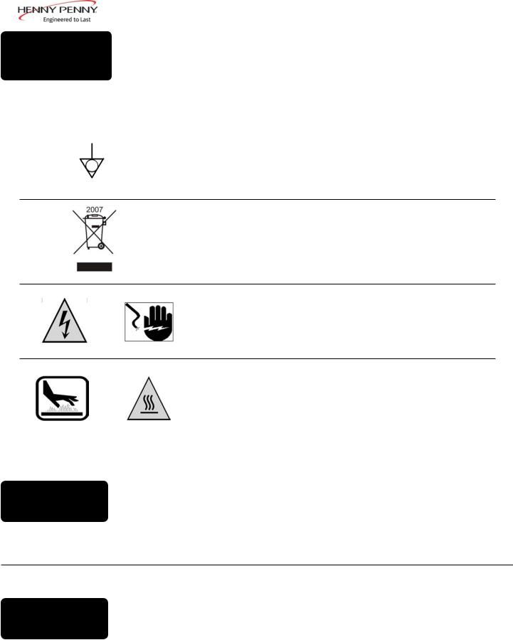
Equipotential Ground Symbol
Waste Electrical and Electronic Equipment (WEEE) Symbol
OR |
Shock Hazard Symbols |
OR
1-2. PROPER CARE
Hot Surface Symbols
As in all Henny Penny equipment, the unit requires care and maintenance. Requirements for maintenance and cleaning are contained in this manual and must be a regular part of the operation of the unit.
1-3. |
Should you require outside assistance, call your local distribu- |
tor in your area, or call 1-800-417-8405 or 1-937-456-8405.for |
|
ASSISTANCE |
Henny Penny Technical Support. |
March 2014 |
2 |
SECTION 2: UNPACKING / INSTALLATION
2-1. INTRODUCTION
This section provides the installation and unpacking instructions.
•Any shipping damage should be noted in the presence of the delivery agent and signed prior to his or her departure.
•Installation of this unit should be performed only by a qualified service technician.
2-2. UNPACKING
March 2014
•Take care when moving the fryer to prevent personal injury. The fryer weighs approximately 877 lbs.(398 Kg).
•Do not puncture the fryer with any objects such as drills or screws as electrical shock or component damage could result.
To avoid personal injury, all counter-weights must be installed and secured before attempting to unlatch the lid.
1.Cut and remove the plastic bands from the main box.
2.Remove the box lid and lift the main box off the fryer.
3.Remove corner packing supports (4).
4.Cut the stretch film from around the carrier/rack box and remove it from the top of the fryer lid.
5.Cut and remove the metal bands holding the fryer to the pallet.
6.Remove the fryer from the pallet. See one unloading method described on 6.
3
2-2. UNPACKING (CONT.)
Do not drop counterweights , or personal injury could result. Each counterweight weighs approximately 20 lbs. (9 kg.) each.
7.Remove the counterweights from the pallet, which are strapped to the pallet, under the fryer.
8.Remove rear service cover.
9.Load the six weights into the counterweight assembly. See page 7.
10.Replace rear service cover.
To avoid personal injury and assure safe operation of unit, rear service cover must be in place.
11.Cut warning tags from the lid assembly. The lid may now be unlatched.
12.Remove the accessories from inside the filter drain pan.
13.Remove the protective paper from the fryer cabinet. Clean exterior surface with a damp cloth.
March 2014 |
4 |
Ramp Unloading
1.Front casters are fixed in the forward position.
2.Pry off the rail on either side of the pallet.
3.Prop up a ramp for each caster on the selected side.
If ramp is not being used, rest the selected side’s casters onto the ground and move to step 4.
4.Tilt and roll the unit off the pallet onto the ramp (if available). The front casters will slide onto the ramp. Pull the pallet from under the unit and set the unit onto the ground.
5.Remove the weights from the pallet.
6.Remove the rear cover. The weight segments must be installed per instructions contained therein before attempting to unlatch the lid.
Dec. 2013 |
5 |

Dec. 2013 |
6 |
2-3. SELECTING THE
LOCATION
The proper location of the fryer is very important for operation, speed, and convenience. Choose a location which provides easy loading and unloading without interfering with the final assembly of food orders. Operators find that frying from raw to finish, and holding the product in a warmer provides fast continuous service. Landing or dumping tables should be provided next to the fryer. The best efficiency will be obtained by a straight line operation, i.e. raw in one side and finish out the other side. Order assembly can be moved away with only a slight loss of efficiency.
To properly service the fryer, 24 inches (60.96 cm) of clearance is needed on all sides of the fryer. Access for servicing by removing a side panel.
To avoid fire and ruined supplies, the area under the fryer should not be used to store supplies.
To prevent severe burns from splashing hot oil, position and install fryer to prevent tipping or movement.
Restraining ties may be used for stabilization.
For proper operation, level the fryer from side to side and front to back.
2-4. Use level on the flat areas around the frypot collar.
LEVELING THE
FRYER
FAILURE TO FOLLOW THESE LEVELING
INSTRUCTIONS CAN RESULT IN OIL
OVERFLOWING THE FRYPOT WHICH COULD
CAUSE SERIOUS BURNS, PERSONAL INJURY,
FIRE AND/OR PROPERTY DAMAGE.
March 2014 |
7 |
2-5. VENTILATION OF FRYER
The fryer should be located with provision for venting into adequate exhaust hood or ventilation system to permit efficient removal of steam exhaust and frying odors. The exhaust canopy must be designed to avoid interference with the operation of the fryer. Consult a local ventilation or heating
company to help in designing an adequate system.
Ventilation must conform to local, state, and national codes. Consult your local fire department or building authorities.
2-6. ELECTRICAL REQUIREMENTS
The electric fryer requires 208, 240 or 480 volt, three phase, 50/60 Hertz service. The power cord may be already attached to the fryer, or provided at installation. Check the data plate to determine the correct power supply.
This fryer must be adequately and safely grounded (earthed) or electrical shock could result. Refer to local electrical codes for correct grounding (earthing) procedures or in absence of local codes, with The National Electrical Code, ANSI/NFPA No. 70-(the current edition). In Canada, all electrical connections are to be made in accordance with CSA C22.1, Canadian Electrical Code Part 1, and/or local codes. To avoid electrical shock, this appliance must be equipped with an external circuit breaker which will disconnect all ungrounded (unearthed) conductors. The main power switch on this appliance does not disconnect all line conductors
A separate disconnect switch meeting overvoltage category III conditions with proper capacity fuses or breakers must be installed at a convenient location between the fryer and the power source. It should be an insulated copper conductor rated for 600 volts and 90o C. For runs longer than 50 feet
(15.24 m), use the next larger wire size.
Aug. 2014 |
8 |
2-7. INTERNATIONAL ELECTRICAL REQUIREMENTS
Units being used outside the United States may not be shipped with the power cord attached to the unit because of the different wiring codes. The fryers are available from the factory wired for 200, 240, 380 and 415 volts, 3 phase, 50 Hertz service. A terminal block is mounted inside the fryer for the cable wiring.
•CE units require a minimum wire size of 4mm to be wired to the terminal block. If a flexible power cord is used, it must be
HO7RN type.
•The supply power cords shall be oil-resistant, sheathed flexible cable, no lighter than ordinary polychloroprene or other equivalent synthetic elastomer-sheathed cord.
•It is recommended that a 30 mA rated protective device such as a residual current circuit breaker (RCCB), or ground fault circuit interrupter (GFCI), be used on the fryer circuit.
(FOR EQUIPMENT WITH CE MARK ONLY!) To prevent electric shock hazard this appliance must be bonded to other appliances or touchable metal surfaces in close proximity to this appliance with an equipotential bonding conductor. This appliance is equipped with an equipotential lug for this purpose. The equipotential lug is marked
with the following symbol 
March 2014 |
9 |
BOIL-OVER PREVENTION IN HENNY PENNY FRYER
FAILURE TO FOLLOW THESE INSTRUCTIONS CAN RESULT
IN OIL OVERFLOWING THE FRYPOT WHICH COULD CAUSE SERIOUS BURNS, PERSONAL INJURY, FIRE AND/OR PROPERTY DAMAGE.
•THE OIL MAY BE STIRRED ONLY DURING THE MORNING START UP PROCEDURE. DO NOT STIR THE OIL AT ANY OTHER TIME.
•BRUSH ALL CRACKLINGS FROM FRYPOT SURFACES DURING THE POT CLEAN OUT PROCESS.
•MAKE SURE THE FRYER IS LEVEL.
•BE CERTAIN THE OIL IS NEVER ABOVE THE UPPER FRYPOT “FILL” LINE.
•BE CERTAIN THAT THE GAS CONTROL VALVE AND BURNERS ARE PROPERLY ADJUSTED. (GAS UNITS ONLY)
•USE RECOMMENDED PRODUCT LOAD SIZE (MAXIMUM 24 LB).
FOR ASSISTANCE CALL THE HENNY PENNY SERVICE DEPARTMENT AT 1-800-417-8405.
OR 1-937-456-8405
Dec. 2013 |
10 |
SECTION 3: OPERATION
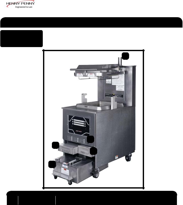
3-1. OPERATING COMPONENTS
1
3
2
4
5
Item |
Description |
Function |
|
No. |
|||
|
|
||
1 |
Steam-Stack |
Houses the dead-weight. Releases steam when pressurized |
|
2 |
Fresh Oil Tank |
Tops the pot off with fresh oil when low |
|
3 |
Power Switch |
Turns power to the unit ON/ OFF |
|
4 |
Condensation Pan |
Reservoir that hold excess condensation that drains from the pot |
|
5 |
Oil Drain Pan |
Oil is drained into this pan and then is pumped through filters to help |
|
|
|
prolong the use of the oil |
Dec. 2013 |
11 |
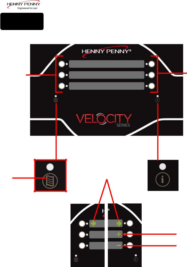
3-2. CONTROL OVERVIEW
1
2
Figure 3-2
This section gives a control board overview and explains all the buttons, displays and features.
1
Figure 3-1
4 |
|
|
|
3 |
|
|
|
||
|
|
|
|
|
Figure 3-3
5
6
Figure 3-4
March 2014 |
12 |

3-2. CONTROL OVERVIEW (CONT.)
Fig. |
Item |
Description |
Function |
|
No. |
||||
|
|
|
||
3-1 |
1 |
Buttons |
When the light is illuminated next to the button, this indicates this button |
|
has a product or action that can be reached by pressing. |
||||
|
|
|
||
|
|
|
|
|
3-2 |
2 |
Menu Button |
Pressing and holding this button will access the “MAIN” menu which |
|
includes features such as filter, info mode, and programming. |
||||
|
|
|
||
|
|
|
• Press this button once to display the pressure and temperature |
|
3-3 |
3 |
Info Button |
• Press this button twice to activate the “WIPE” feature |
|
|
|
|
• Press this button three times to get “LAST FILTER” information |
|
|
|
|
|
|
3-4 |
4 |
Arrow Displays |
When an arrow is displayed, this indicates there is another screen or option. |
|
To access the next option/screen, press the button next to the desired arrow. |
||||
|
|
|
||
|
|
|
|
|
|
|
|
The plus sign is displayed when the value of the time/temp/letters can be |
|
3-4 |
5 |
Plus Display |
changed. Pressing the button next to the plus sign will increase the value. |
|
|
||||
|
|
|
Will be represented in the manual by: + |
|
|
|
|
The minus sign is displayed when the value of the time/temp/letters can be |
|
3-4 |
6 |
Minus Display |
changed. Pressing the button next to the minus sign will decrease the value. |
|
|
||||
|
|
|
Will be represented in the manual by: - |
Sept. 2014 |
13 |
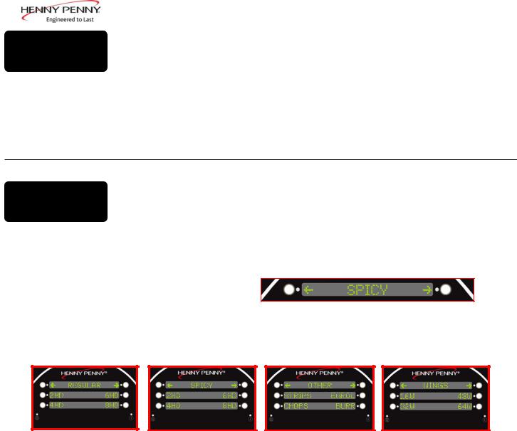
3-3. DISPLAY OPTIONS
This section describes the three (3) cook display options that this unit is equipped with. The three options are as listed below:
•4+TITLE
•5+NEXT
•6 ITEMS
To change the display option, see SPECIAL PROGRAM section.
3-4. 4+TITLE OPTION
The 4+TITLE option shows up to four cook items along with the title of the particular menu you are in.
When in a cook menu, the title of the menu will be displayed in the top section.
Pressing the either arrow button will allow you to scroll right or left through each menu option.
Pressing the button next to the item you want to cook starts the heating process. ”DROP>” will be displayed when unit is ready to cook the selected item.
March 2014 |
14 |
3-5. 5+NEXT OPTION
The 5+NEXT option ashows up to five cook items, along with a button that steps to the next cook menu.
All the cook options are displayed on the screen with the bot- tom-right reading “next>”. Pressing the button next to “next>” will access the next set of cook options.
3-6.
6 ITEMS OPTION
The 6 ITEM option lets the user control all six items on the cook menu. If there is more than one cook menu, the user must program navigation links to other menus.
If there are more than 6 products that will be cooked, and this option is selected, one of the buttons must be designated as a link to a sub-menu, or those options will not be accessible in this option.
See the programming section for information on setting up menus.
March 2014 |
15 |
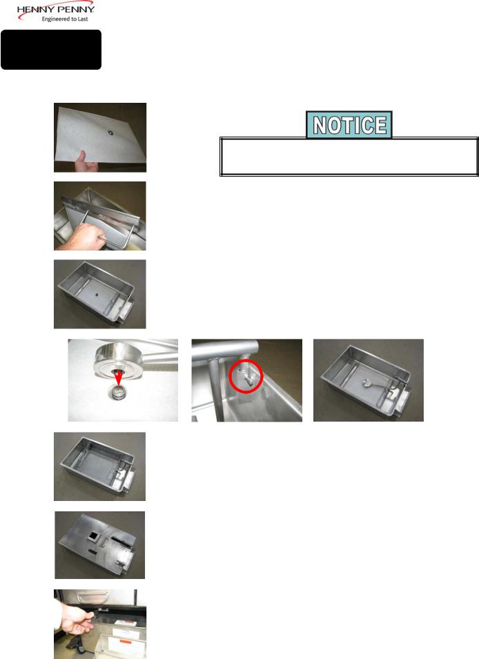
3-7. DRAIN PAN ASSEMBLY
1.Slide a filter envelope onto the filter screen so the plug is protruding through the hole.
During assembly, be sure to apply oil to all O-rings to lubricate to help prevent tears and loss.
2.Slide the two handle clamps onto the ends of the filter screen assembly with the handles facing the same direction of the plug.
3.Place the filter screen into the bottom of the drain pan with the plug side up.
4.Lining up the hole of the pickup tube with the plug of the filter screen, press the tube down.
5.Position the pick up tube so that the guides slide into the notches located on the holder in the front of the drain pan. Press down on the pick up tube to confirm it is fully engaged on the filter screen plug and in the holder.
6.Place the crumb catcher into the drain pan so the legs straddle the filter screen.
7.Place lid onto drain pan.
8.Push the drain pan into place and lock it into place using the locking latch.
9.To remove the drain pan for cleaning, reverse this procedure.
Dec. 2013 |
16 |
 Loading...