


OPERATOR’S
M A N U A L
PRESSURE FRYER (Gas)
MODEL
PFG-690
PFG-692
R E G I S T E R WA R R A N T Y O N L I N E AT W W W. H E N N Y P E N N Y. C O M
This manual should be retained in a convenient location for future reference.
A wiring diagram for this appliance is located on the rear shroud cover of the control panel.
Post in a prominent location, instructions to be followed if user smells gas. This information should be obtained by consulting the local gas supplier.
Do not obstruct the flow of combustion and ventilation air. Adequate clearance must be left all around appliance for sufficient air to the combustion chamber.
The Model PFG-690 pressure fryer is equipped with a continuous pilot. But fryer cannot be operated with out electric power. Fryer will automatically return to normal operation when power is restored.
Keep appliance area free and clear from combustibles.
Improper installation, adjustment, alteration, service or maintenance can cause property damage, injury or death. Read the installation, operating and maintenance instructions thoroughly before installing or servicing this
equipment.
DO NOT STORE OR USE GASOLINE OR OTHER FLAMMABLE VAPORS AND LIQUIDS IN THE VICINITY OF THIS OR ANY OTHER APPLIANCE. FIRE OR EXPLOSION COULD RESULT.
Aug. 2003

|
Technical Data for CE Marked Products |
||
Nominal Heat Input: |
Natural (I2H) = 26,4 kW |
(90,000 Btu/h) |
|
(Net) |
Natural (I2E) = 26,4 kW (90,000 Btu/h) |
||
|
Natural (I2S) = 23,75 kW (81,000 Btu/h) |
||
|
Liquid Propane (I3P) = 27,0 kW |
(92,000 Btu/h) |
|
Nominal Heat Input: |
Natural (I2H) = 29,3 kW |
(100,000 Btu/h) |
|
(Gross) |
Natural (I2E) = 29,3 kW (100,000 Btu/h) |
||
|
Natural (I2S) = 26,4 kW (90,000 Btu/h) |
||
|
Liquid Propane (I3P) = 29,3 kW |
(100,000 Btu/h) |
|
Supply Pressure: |
Natural (I2H) = 20 mbar |
|
|
|
Natural (I2E) = 20 mbar |
|
|
|
Natural (I2S) = 25 mbar |
|
|
|
Liquid Propane (I3P) = 37/50 mbar |
||
Test Point Pressure: |
Natural (I2H) = 8,7 mbar |
|
|
|
Natural (I2E) = 8,7 mbar |
|
|
|
Natural (I2S) = 8,7 mbar |
|
|
|
Liquid Propane (I3P) = 25 mbar |
|
|
Injector Size: |
Natural (I2H) = 2,51 mm |
|
|
Natural (I2E) = 2.51 mm Natural (I2S) = 2.85 mm
Liquid Propane (I3P) = 1,40 mm
This appliance must be installed in accordance with the manufacturer’s instructions and the regulations in force and only used in a suitable ventilated location. Read the instructions fully before installing or using the appliance.
|
Datos Tecnicos Para Products CE |
||
Consumo Calorico Nominal: |
Gas Natural (I2H) = 26,4 kW |
(90,000 Btu/h) |
|
(Neto) |
Gas Natural (I2E) = 26,4 kW (90,000 Btu/h) |
||
|
Gas Natural (I2S) = 23,75 kW (81,000 Btu/h) |
||
|
Propano Licuado (I3P) = 27,0 kW |
(92,000 Btu/h) |
|
Consumo Calorico Nominal: |
Gas Natural (I2H) = 29,3 kW |
(100,000 Btu/h) |
|
(Bruto) |
Gas Natural (I2E) = 29,3 kW (100,000 Btu/h) |
||
|
Gas Natural (I2S) = 26,4 kW (90,000 Btu/h) |
||
|
Propano Licuado (I3P) = 29,3 kW |
(100,000 Btu/h) |
|
Presion De Alimentacion: |
Gas Natural (I2H) = 20 mbar |
|
|
|
Gas Natural (I2E) = 20 mbar |
|
|
|
Gas Natural (I2S) = 25 mbar |
|
|
|
Propano Licuado (I3P) = 37/50 mbar |
||
Presion En Ez Punto De Prueba: |
Gas Natural (I2H) = 8,7 mbar |
|
|
|
Gas Natural (I2E) = 8,7 mbar |
|
|
|
Gas Natural (I2S) = 8,7 mbar |
|
|
|
Propano Licuado (I3P) = 25 mbar |
|
|
Diámetro Boquilla: |
Gas Natural (I2H) = 2,51 mm |
|
|
Gas Natural (I2E) = 2.51 mm Gas Natural (I2S) = 2.85 mm Propano Licuado (I3P) = 1,40 mm
Este equipo debe instalarse únicamente en un recinto adecuadameute ventilado y conforme a las indicaciones del fabricante y a las normas vigentes. Lea completamente las instrucciones antes de instalar o usar este equipo.

HENNY PENNY
8 HEAD GAS PRESSURE FRYER
SPECIFICATIONS
Height |
61” (155 cm) |
Width |
24” (61 cm) |
Depth |
41¾” (106 cm) |
Floor Space |
Approximately 7 sq. ft. (0.65 sq. m.) |
Pot Capacity |
8 head of chicken (24 lbs.) (10.9 kg) |
|
130 lbs. shortening (59 kg) |
Electrical |
120 VAC, 1 Phase, 50/60 Hz, 10 Amp, 3 Wire Service |
|
230 VAC, 1 Phase, 50 Hz, 3 Wire Service |
Heating |
Propane or Natural Gas; 100,000 btu/hr (105 MJ/hr) |
Pressure |
12 psi operating pressure (827 mbar) |
|
14.5 psi safety relief pressure (999 mbar) |
Shipping Weight |
Approximately 935 lbs. (424 kg) |
A data plate, located on the back shroud behind the lid, gives the information of the type of fryer, serial number, warranty date, and other information pertaining to fryer. Also, the serialnumber is stamped on the outside of the frypot. See figure below.

TABLE OF CONTENTS
Section |
|
|
Page |
Section 1. |
INTRODUCTION...................................................................................................... |
3 |
|
|
1-1. |
Pressure Fryer................................................................................................ |
3 |
|
1-2. |
Proper Care.................................................................................................... |
3 |
|
1-3. |
Assistance....................................................................................................... |
3 |
|
1-4. |
Safety............................................................................................................. |
4 |
Section 2. |
INSTALLATION........................................................................................................ |
5 |
|
|
2-1. |
Introduction.................................................................................................... |
5 |
|
2-2. |
Unpacking Instructions.................................................................................. |
5 |
|
2-3. |
Selecting the Location.................................................................................... |
9 |
|
2-4. |
Leveling the Fryer.......................................................................................... |
9 |
|
2-5. |
Ventilation of Fryer........................................................................................ |
10 |
|
2-6. |
Gas Supply..................................................................................................... |
10 |
|
2-7. |
Gas Leak Test................................................................................................. |
13 |
|
2-8. |
Gas Pressure Regulator Setting...................................................................... |
13 |
|
2-9. |
Electrical Requirements................................................................................. |
15 |
Section 3. |
OPERATION INSTRUCTIONS................................................................................ |
17 |
|
|
3-1. |
Operating Components.................................................................................. |
17 |
|
3-2. |
Lid Operation................................................................................................. |
21 |
|
3-3. |
Melt Cycle Operation..................................................................................... |
22 |
|
3-4. |
Controls and Indicators.................................................................................. |
23 |
|
3-5. |
Display Messages........................................................................................... |
24 |
|
3-6. |
Filling or Adding Shortening......................................................................... |
25 |
|
3-7. |
Basic Operation.............................................................................................. |
26 |
|
3-8. |
Care of the Shortening................................................................................... |
28 |
|
3-9. |
Filtering of Shortening................................................................................... |
29 |
|
3-10. |
Changing the Filter Envelope........................................................................ |
31 |
|
3-11. |
Lighting and Shutdown of the Burners.......................................................... |
31 |
|
3-12. |
Cleaning the Frypot........................................................................................ |
32 |
|
3-13. |
Filter Pump Motor Protector-Manual Reset................................................... |
33 |
|
3-14. |
Regular Maintenance Schedule...................................................................... |
33 |
|
3-15. |
Preventive Maintenance................................................................................. |
34 |
|
3-16. |
Programming.................................................................................................. |
40 |
|
3-17. |
Special Program Mode................................................................................... |
42 |
Section 4. |
TROUBLESHOOTING.............................................................................................. |
47 |
|
|
4-1. |
Troubleshooting Guide................................................................................... |
47 |
|
4-2. |
Error Codes..................................................................................................... |
48 |
Distributors List - Domestic and International
June 2012 |
i |

HENNY PENNY
8 HEAD ELECTRIC PRESSURE FRYER
Fryer must be installed and used in such a way to prevent water from contacting the shortening.
This appliance is not intended to be operated by means of an external timer or a separate remote control system.
This appliance is not intended for use by persons (including children) with reduced physical, sensory or mental capabilities, or lack of experience and knowledge, unless they have been given supervision or instruction concerning use of the appliance by a person responsible for their safety.

1-1. PRESSURE FRYER
1-2. PROPER CARE
1-3. ASSISTANCE
SECTION1:INTRODUCTION
The Henny Penny Pressure Fryer is a basic unit of food processing equipment which is used only in institutional and commercial food service operations.
P-H-T
A combination of pressure, heat, and time is automatically controlled to produce the optimum in a tasty, appealing product.
PRESSURE
Pressure is basic to this method of food preparation. The pressure is developed from the natural moisture of the food. The patented lid traps this moisture and uses it as steam. Because the steam builds rapidly, a greater part of the natural juices are retained within the food. A deadweight assembly vents excess steam from the pot and maintains constant live steam pressure.
HEAT
Heat generated is another important factor of the pressure fryer. Energy savings is realized due to the unit’s short frying time, low temperature, and heat retention of the stainless steel frypot.
TIME
Time is important because the shorter time involved in frying foods results in additional economies for the user. Foods are table ready in less time than it would take to fry them in a conventional open-type fryer.
As of August 16, 2005, the Waste Electrical and Electronic Equipment directive went into effect for the European Union. Our products have been evaluated to the WEEE directive. We have also reviewed our products to determine if they comply with the Restriction of Hazardous Substances directive (RoHS) and have redesigned our products as needed in order to comply. To continue compliance with these directives, this unit must not be disposed as unsorted municipal waste. For proper disposal, please contact your nearest Henny Penny distributor.
As in any unit of food service equipment, the Henny Penny Pressure Fryer does require care and maintenance. Requirements for the maintenance and cleaning are contained in this manual and must become a regular part of the operation of the unit at all times.
Should you require outside assistance, call your local independent distributor in your area, call Henny Penny Corp. at 1-800-417-8405 or 1-937-456-8405, or go to Henny Penny online at www.hennypenny.com.
Feb. 2007 |
3 |
1-4. SAFETY
The instructions in this manual have been prepared to aid you in learning the proper procedures for your equipment. Where information is of particular importance or is safety related, the words NOTICE, CAUTION, or WARNING are used. Their usage is described below.
If a problem occurs during the first operation of a new unit, recheck the Installation Section of the Operator’s Manual.
Before troubleshooting, always recheck the Operation
Section of the Operator’s Manual.
Where information is of particular importance or is safety related, the words DANGER, WARNING, CAUTION, or NOTICE are used. Their
usage is described as follows:
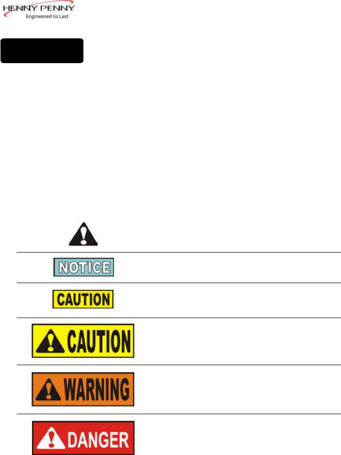
SAFETYALERT SYMBOL is used with DANGER, WARNING or CAUTION which indicates a personal injury type hazard.
NOTICE is used to highlight especially important information.
CAUTION used without the safety alert symbol indicates a potentially hazardous situation which, if not avoided, may result in property damage.
CAUTION used with the safety alert symbol indicates a potentially hazardous situation which, if not avoided, could result in minor or moderate injury.
WARNING indicates a potentially hazardous situation which, if not avoided, could result in death or serious injury.
DANGER INDICATES AN IMMINENTLY HAZARDOUS SITUATIONWHICH,IFNOTAVOIDED,WILLRESULTIN DEATH OR SERIOUS INJURY.
July 2003 |
4 |

2-1. INTRODUCTION
2-2. UNPACKING INSTRUCTIONS
SECTION 2: INSTALLATION
This section provides the installation and unpacking instructions for the Henny Penny PFG-690.
Installation of this unit should be performed only by a qualified service technician.
Do not puncture the fryer with any objects such as drills or screws as electrical shock or component damage could result.
Any shipping damage should be noted in the presence of the delivery agent and signed prior to his or her departure.
1.Cut and remove the plastic bands from the main box.
2.Remove the box lid and lift the main box off the fryer.
3.Remove four corner packing supports.
4.Cut the stretch film from around the carrier/rack box and remove it from the top of the fryer lid.
5.Cut and remove the metal bands holding the fryer to the pallet.
All counterweights must be loaded before unlatching the lid, or personal injury could result.
6. Remove the fryer from the pallet.
Take care when moving the fryer to prevent personal injury. The fryer weighs approximately 935 lbs. (424 kg).
July 2003 |
5 |
2-2. UNPACKING INSTRUCTIONS (CONT.)
CAP
DEAD
 WEIGHT
SHIPPING SUPPORT (DISCARD)
HOUSING
7.Remove the counterweights, which are strapped to the pallet under the fryer, from the pallet.
Do not drop. The counterweights weigh approximately 18 lbs. (8.1 kg) each. Handle with care, or personal injury could result.
8.Remove rear service cover.
9.Load the 7 weights into the counterweight assembly.
10.Replace rear service cover.
To avoid personal injury and assure safe operation of unit, rear service cover must be in place.
11.Cut warning tags from the lid assembly. The lid may now be unlatched.
12.Remove the accessories from inside the filter drain pan.
The fittings for installing the gas line are in a separate box, along with the accessories, in the filter drain pan.
13. Prepare the deadweight valve for operation
The metal shipping support is placed within the deadweight assembly housing to protect the deadweight orifice and deadweight during shipment. This support must be removed prior to installation and start-up.
a.Unscrew the deadweight cap.
b.Remove the deadweight.
c.Remove and discard the shipping support.
d.Clean the deadweight orifice with a dry cloth.
e.Carefully place deadweight over deadweight orifice. Replace deadweight cap, finger tight.
14.Remove the protective paper from the fryer cabinet. Clean exterior surface with a damp cloth.
Dec. 2016 |
6 |

2016 .Dec
ROLL UNIT OFF
PALLET ONTO RAMP.
7
ORIENT CASTERS IN SIDEWAYS
POSITION. RAISE SIDE SLIGHTLY &
KNOCK OUT RUBBER PADS (2). -
TYPICAL BOTH SIDES
PRY OFF RAIL -
EITHER SIDE
PROP UP A RAMP FOR EACH
CASTER ONTHE SELECTED SIDE.
REMOVE REAR COVER - WEIGHT SEGMENTS MUST BE INSTALLED PER INSTRUCTION CONTAINED THEREIN BEFORE ATTEMPTING TO UNLATCH LID.
REMOVE THE ACCESSORIES FROM THE DRAIN PAN.
NOTE: THE FITTINGS FOR GAS LINE ARE HERE!!
REMOVE THE WEIGHTS FROM THE PALLET.
Unloading Ramp Optional

A |
REMOVE 2 BOLTS MARKED |
|
“A” TO RELEASE FRAME |
|
AFTER INSTALLING WEIGHT |
|
SEGMENTS |
A

 INSERT 4TH
INSERT 2ND & 3RD
SEGMENT
INSERT 1ST
SEGMENT
EACH WEIGHT SEGMENT WEIGHS APPROXIMATELY 18 LBS. (8.1 KG) - HANDLE WITH CARE
ALL SEGMENTS ARE IDENTICAL.
 ALL SEGMENTS MUST BE INSTALLED AND SECURED IN THE FRAM BEFORE ATTEMPTING TO UNLATCH LID.
Dec. 2016 |
8 |
2-3. SELECTING THE LOCATION
2-4. LEVELING THE FRYER
The proper location of the fryer is very important for operation, speed, and convenience. Choose a location which will provide easy loading and unloading without interfering with the final assembly of food orders. Operators have found that frying from raw to finish, and holding the product in a warmer provides fast, continuous service. Landing or dumping tables should be
provided next to, at least, one side of the fryer. Keep in mind the best efficiency will be obtained by a straight line operation, i.e., raw in one side and finish out the other side. Order assembly can be moved away with only a slight loss of efficiency. To properly service the fryer, 24 inches (60.96 cm) of clearance is needed
on all sides of the fryer. Access for servicing can be attained by removing a side panel. Also, at least 6 inches (15.24 cm) around the base of the unit is needed for proper air supply to the combustion chamber.
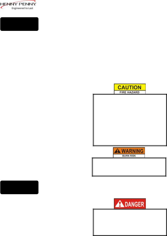
To avoid a fire, install the fryer with minimum clearance from all combustible and noncombustible materials, 6 inches (15.24 cm) from side and 6 inches (15.24 cm) from back. If installed properly, the gas fryer is designed for operation on combustible floors and adjacent to combustible walls.
To avoid fire and ruined supplies, the area under the
690 fryer should not be used to store supplies.
Do not spray aerosols in the vicinity of this appliance while it is in operation.
To prevent severe burns from splashing hot shortening, position and install fryer to prevent tipping or movement. Restraining ties may be used for stabilization.
For proper operation, level the fryer from side to side and front to back, using level on the flat areas around the frypot collar.
FAILURE TO FOLLOW THESE LEVELING
INSTRUCTIONS CAN RESULT IN
SHORTENING OVERFLOWING THE FRYPOT WHICH COULD CAUSE SERIOUS BURNS, PERSONALINJURY, FIRE,AND/OR PROPERTY DAMAGE.
April 2008 |
9 |
2-5.
VENTILATION OF
FRYER
2-6. GAS SUPPLY
.525 in.
1.33 cm
35.277 in.
89.6 cm
July 2003
The fryer must be located with provision for venting into adequate exhaust hood or ventilation system. This is essential to permit efficient removal of the flue gases and frying odors. Special precaution must be taken in designing an exhaust canopy to avoid interference with the operation of the fryer. We recommend you consult a local ventilation or heating company to help in designing an adequate system.
Ventilation must conform to local, state, and national codes. Consult your local fire department or building authorities.
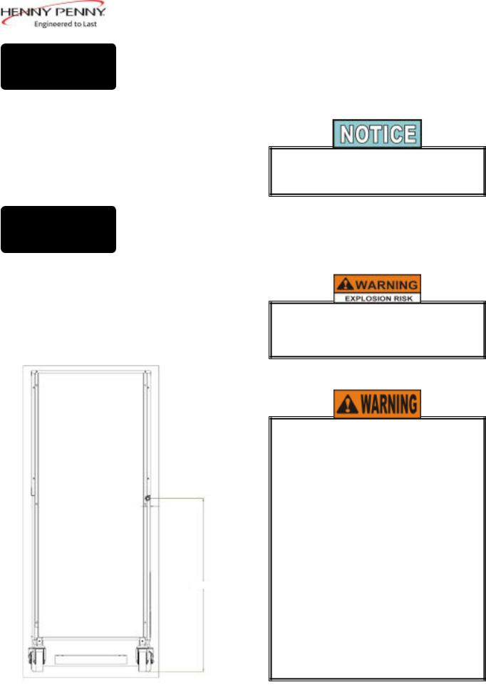
The gas fryer is factory available for either natural or propane gas. Check the data plate on the right side panel of the cabinet to determine the proper gas supply requirements. The minimum supply for natural gas is 7 inches water column (1.74 kPa), and 10 inches water column (2.49 kPa) for propane.
Do not attempt to use any gas other than that specified on the data plate. Incorrect gas supply could cause a fire or explosion resulting in severe injuries and/or property damage.
Please refer below for the recommended hookup of the fryer to main gas line supply.
To avoid possible serious personal injury:
•Installation must conform with local, state, and national codes, and be
in accordance with Canadian Gas Authority Standard CSA B149-& 2, Installation Codes - Gas Burning Appliances and in accordance with Australian Gas Association current edition of AS5601 Gas Installations.
•The fryer and its manual shutoff valve must be disconnected from the gas supply piping system during any pressure testing of that system at test
pressures in excess of 1/2 psig (3.45kPa) (34.47mbar)
(continued to next page)
10
2-6. GAS SUPPLY
(CONT.)
July 2003
•The fryer must be isolated from the gas supply piping system by closing its manual shutoff valve during any pressure testing of the gas supply piping system at test pressures equal to or less than 1/2 psig (3.45 kPa)(34.47 mbar).
•A standard 3/4 inch, black steel pipe and malleable fittings should be used for gas service connections.
•Do not use cast iron fittings.
•Although 3/4 inch size pipe recommended, piping should be of adequate size and installed to provide a supply of gas sufficient to meet the maximum demand without undue loss of pressure between the meter and the fryer. The pressure loss in the piping system should not exceed 0.3 inch water column (0.747 mbar).
Provisions should be made for moving the fryer for cleaning and servicing. This may be accomplished by:
1.Installing a manual gas shutoff valve and disconnect union, or
2.Installing a heavy-duty (min. 3/4 inch) design A.G.A.
certified connector which complies with standard connectors for moveable gas appliances. ANSI Z21.69 or CAN/CSA 6.16. Also, a quick-disconnect coupling which complies with the Standard for Quick-Disconnect Devices for use
with Gas Fuel, ANSI Z21.41 or CAN 1-6.9. Also, adequate means must be provided to limit the movement of the fryer without depending on the connector and any quick-disconnect device or its associated piping to limit the fryer movement.
3.See the illustration on the following page for the proper connections of the flexible gas line and cable restraint.
The cable restraint limits the distance the fryer can be pulled from the wall. For cleaning and servicing the fryer, the cable must be unsnapped from the unit and the flexible
gas line disconnected. This will allow better access to all sides of the fryer. The gas line and cable restraint must be reconnected once the cleaning or servicing is complete.
11

2-6. GAS SUPPLY
(CONT.)
GAS PIPING
MINIMUM PULL of equipment away from wall permissible for accessibility to Quick Disconnect Device
DISCONNECT |
BEFORE |
MAXIMUM PULL |
MINIMUM PULL FOR |
ACCESSIBILITY |
ONLY |
AVOID SHARP BENDS AND KINKS when pulling equipment away from wall. (Maximum pull will kink ends, even if installed properly, and reduce Connector life.)
QUICK DISCONNECT DEVICE still attached while extended at maximum pull
STRESS STRESS
POINTS POINTS
MAXIMUM PULL NOT
ADVISED WHILE
CONNECTED
Couplings and hose should be installed in the same plane as shown at left. DO NOT OFFSET COUPLINGS -- this causes torsional twisting and undue strain causing premature failure
This is the correct way to

 install metal hose vor
 vertical traverse. Note the


 single, natural loop.
 Allowing a sharp bend, as shown at right, strains and
  twists the metal hose to a
point of early failure at the coupling
Maintain the minimum or larger bending diameter between the couplings for longest life.
Closing in the diameter at the coupling, as shown at right, creates double bends causing work work fatigue failure of the fittings.
In all installations where


 “self-draining” is not
necessary, connect metal
hose in a vertical loop. DO NOT CONNECT METAL HOSE HORIZONTALLY...unless
“self-draining” is necessary,
then use support on lower plane as shown at left.
CABLE RESTRAINT
Please refer to the illustration below when installing cable restraint on all moveable gas fryers.
I-bolt is to be secured to the building using acceptable building contruction practices.
DRY WALL CONSTRUCTION
Secure I-bolt to a building stud DO NOT attach to dry wall only. Also, locate the I-bolt at teh same height as the gas service. Preferred installation is approximately six inches to either side of service. Cable restraint must be at least six inches shorter than flexible gas line.
Utilize elbows when necesary to avoid sharp kinks or excessive bending. For ease of movement, install with a “lazy” loop. gas appliance must be disconnected prior to maximum movement. (Minimum movement is permissible for hose disconnection).
12160004
Dec. 2016 |
12 |
 Loading...