


OFE-321

OPERATOR’S
MANUAL
REGISTER WARRANTY ONLINE AT WWW.HENNYPENNY.COM
OPEN FRYER
MODEL
OFE/OFG-321
OFE/OFG-322
OFE/OFG-323
OFE/OFG-324
OEA/OGA-321
OEA/OGA-322
OEA/OGA-323
OEA/OGA-324
ODE/ODG-323

Model OFE/OFG-321,322,323,324
This manual should be retained in a convenient location for future reference.
A wiring diagram for this appliance is located on the inside of the right side panel.
Post in a prominent location, instructions to be followed in event user smells gas. This information shall
be obtained by consulting the local gas supplier.
Do not obstruct the flow of combustion and ventilation air. Adequate clearance must be left all around
appliance for sufficient air to the combustion chamber.
The Model OFG/OGA-32X open fryer is equipped with a continuous pilot. But the open fryer cannot be
operated without electric power. The unit will automatically return to normal operation when power is
restored.
To avoid a fire, keep appliance area free and clear from combustibles.
Improper installation, adjustment, alteration, service, or maintenance can cause property damage,
injury, or death. Read the installation, operating, and maintenance instructions thoroughly before
installing or servicing this equipment.
DO NOT STORE OR USE GASOLINE OR OTHER FLAMMABLE VAPORS
AND LIQUIDS IN THE VICINITY OF THIS OR ANY OTHER APPLIANCE. FIRE OR
EXPLOSION COULD RESULT.

Model OFE/OFG-321,322,323,324
Technical Data for CE/AGA Marked Products
Nominal Heat Input: Natural (I
2H
) = 24.9 KW (85,000 Btu/h)
(Net) Natural (I
2E
) = 24.9 KW (85,000 Btu/h)
Natural (I
2E
+) = 24.9 KW (85,000 Btu/h)
Natural (I
2L
) = 24.9 KW (85,000 Btu/h)
Liquid Propane (I
3P
) = 24.9 KW (85,000 Btu/h)
Nominal Heat Input: Natural (I
2H
) = 27.7 KW (99.70 MJ/h) (94,500 Btu/h)
(Gross) Natural (I
2E
) = 27.7 KW (94,500 Btu/h)
Natural (I
2E
+) = 27.7 KW (94,500 Btu/h)
Natural (I
2L
) = 27.7 KW (94,500 Btu/h)
Liquid Propane (I
3P
) = 27.7 KW (99.70 MJ/h) (94,500 Btu/h)
Supply Pressure: Natural (I
2H
) = 20 mbar (2.0 kPa)
Natural (I
2E
) = 20 mbar
Natural (I
2E
+) = 20/25 mbar
Natural (I
2L
) = 25 mbar
Liquid Propane (I
3P
) = 30 mbar
Liquid Propane (I
3P
) = 37 mbar (3.7 kPa)
Liquid Propane (I
3P
) = 50 mbar (5.0 kPa)
Test Point Pressure: Natural (I
2H
) = 8.7 mbar (0.87 kPa)
Natural (I
2E
) = 8.7 mbar
Natural (I
2E
+) = N/A
Natural (I
2L
) = 10 mbar
Liquid Propane (I3P) = 24.5 mbar (2.5 kPa)
Injector Size: Natural (I
2H
) = 3.26 mm
Natural (I
2E
) = 3.26 mm
Natural (I
2E
+) = 2.70 mm
Natural (I
2L
) = 3.26 mm
Liquid Propane (I
3P
) = 1.99 mm
This appliance must be installed in accordance with the manufacturer’s instructions and the regulations
in force and only used in a suitably ventilated location. Read the instructions fully before installing or
using the appliance.
Noise generated from this equipment is less than 70 dB(A)
Apr. 2013

Model OFE/OFG-321,322,323,324
TABLE OF CONTENTS
Section Page
Section 1. INTRODUCTION.............................................................................................................1-1
1-1. Introduction .............................................................................................................1-1
1-2. Features ...................................................................................................................1-1
1-3. Proper Care .............................................................................................................1-1
1-4. Assistance ...............................................................................................................1-1
1-5. Safety ......................................................................................................................1-2
Section 2. INSTALLATION ..............................................................................................................2-1
2-1. Introduction .............................................................................................................2-1
2-2. Unpacking ............................................................................................................... 2-1
2-3. Selecting the Location .............................................................................................2-2
2-4. Leveling the Open Fryer .........................................................................................2-2
2-5. Ventilation of Open Fryer .......................................................................................2-2
2-6. Gas Supply ..............................................................................................................2-3
2-7. Gas Leak Test ..........................................................................................................2-6
2-8. Gas Pressure Regulator Setting ...............................................................................2-6
2-9. Electrical Requirements OFG-320 Series ...............................................................2-6
2-10. Electrical Requirements OFE-320 Series ...............................................................2-7
2-11. Testing the Fryer .....................................................................................................2-8
2-12. Joining Instructions ................................................................................................2-8
Section 3. OPERATION ....................................................................................................................3-1
3-1. Operating Components C1000 Controls .................................................................3-1
3-2. Operating Components 6 & 12 Button Controls .....................................................3-3
3-3. Clock Set .................................................................................................................3-7
3-4. Filling or Adding Shortening ..................................................................................3-9
3-5. C1000 Operations and Procedures ..........................................................................3-10
3-6. C1000 Programming Instructions ...........................................................................3-11
3-7. C1000 Special Programming ..................................................................................3-12
3-8. Basic Operations and Procedures (6 Product Controls) ..........................................3-13
3-9. Basic Operations and Procedures (12 Product Controls/Auto-Lift) .......................3-15
3-10. Care of Shortening ..................................................................................................3-17
3-11. Filtering of Shortening ............................................................................................3-18
3-12. Filter Pump Problem Prevention .............................................................................3-22
3-13. Filter Pump Motor Protector - Manual Reset .........................................................3-22
3-14. Changing the Filter Envelope .................................................................................3-22
3-15. Cleaning the Frypot .................................................................................................3-24
3-16. Clean-Out Mode ......................................................................................................2-26
3-17. Operating Instructions for Optional Direct-Connect Shortening System ...............3-27
3-18. Lighting and Shutdown of the Burners ...................................................................3-28
3-19. High Temperature Limit Control ............................................................................3-29
3-17. Regular Maintenance ..............................................................................................3-29
Feb. 2011 i

Model OFE/OFG-321,322,323,324
TABLE OF CONTENTS
Section Page
Section 4. PROGRAMMING – 6 & 12 PRODUCT CONTROLS ..................................................4-1
4-1. Introduction .............................................................................................................4-1
4-2. Product Program Mode ...........................................................................................4-1
4-3. Special Program Mode ............................................................................................4-4
4-4. Data Logging, Heat Control, Tech, and Stat Modes ...............................................4-15
Section 5. TROUBLESHOOTING ...................................................................................................5-1
5-1. Troubleshooting Guide ...........................................................................................5-1
5-2. Error Codes .............................................................................................................5-2
Section 6. INFORMATION MODE .................................................................................................6-1
GLOSSARY ....................................................................................................................G-1
Distributors List - Domestic and International
I Mar, 2008
Model OFE/OFG-321,322,323,324
SECTION 1. INTRODUCTION
1-1. INTRODUCTION The Henny Penny Open Fryer is a basic unit of food
equipment designed to cook foods better and easier. The
microcomputer-based design helps make this possible. This
unit is used only in institutional and commercial food service
operations.
As of August 16, 2005, the Waste Electrical and
Electronic Equipment directive went into effect for the
European Union. Our products have been evaluated to
the WEEE directive. We have also reviewed our
products to determine if they comply with the
Restriction of Hazardous Substances directive (RoHS)
and have redesigned our products as needed in order to
comply. To continue compliance with these directives,
this unit must not be disposed as unsorted municipal
waste. For proper disposal, please contact your nearest
Henny Penny distributor.
1-2. FEATURES • Easily cleaned
• Full frypot 65 lbs. (29.5 kg.) shortening capacity
• Split frypot 25 lbs. (11.3 kg.) shortening cap. (elec. only)
• 2 Half size baskets per well (or full size baskets)
• Stainless steel construction
• Manual reset high limit control
• Self-diagnostic system built into controls
• Built in filter (handles all 3 wells)
• Propane or natural gas; 85,000 btu/pot (26.38 kw)
• Energy Save Mode upon activation for gas fryers
• Many combinations of split frypot/full frypot fryers
• Simplistic electronic Computron 1000 controls available,
or more diverse multifunctional controls available
1-3. PROPER CARE As in any unit of food servicing equipment, the open fryer
does require care and maintenance. Requirements for the
maintenance and cleaning are contained in this manual and
must become a regular part of the operation of the unit at all
times.
1-4. ASSISTANCE Should you require outside assistance, call your local
independent Henny Penny distributor in your area, call
Henny Penny Corp. at 1-800-417-8405 or 1-937-456-8405, or
go to Henny Penny online at www.hennypenny.com.
Jan. 2008 1-1

Model OFE/OFG-321,322,323,324
1-5. SAFETY The Henny Penny Open Fryer has many safety features
incorporated. However, the only way to ensure safe
operation is to fully understand the proper installation,
operation, and maintenance procedures. The instructions in
this manual have been prepared to aid you in learning the
proper procedures.
This appliance is not intended for use by persons (including
children) with reduced physical, sensory or mental capabilities, or
lack of experience and knowledge, unless they have been given
supervision or instruction concerning use of the appliance by a
person responsible for their safety.
Where information is of particular importance or is safety
related, the words DANGER, WARNING, CAUTION, or
NOTE are used. Their usage is described below:
1-2 June 2011
DANGER INDICATES AN IMMINENTLY
HAZARDOUS SITUATION WHICH, IF NOT
AVOIDED, WILL RESULT IN DEATH OR
SERIOUS INJURY.
WARNING indicates a potentially hazardous
situation which, if not avoided, could result in death
or serious injury.
CAUTION used with the safety alert symbol indicates a
potentially hazardous situation which, if not avoided,
could result in minor or moderate injury.
CAUTION used without the safety alert symbol indicates
a potentially hazardous situation which, if not avoided,
may result in property damage.
NOTICE is used to highlight especially important
information.
SAFETY ALERT SYMBOL is used with
DANGER, WARNING or CAUTION which
indicates a personal injury type hazard.
Model OFE/OFG-321,322,323,324
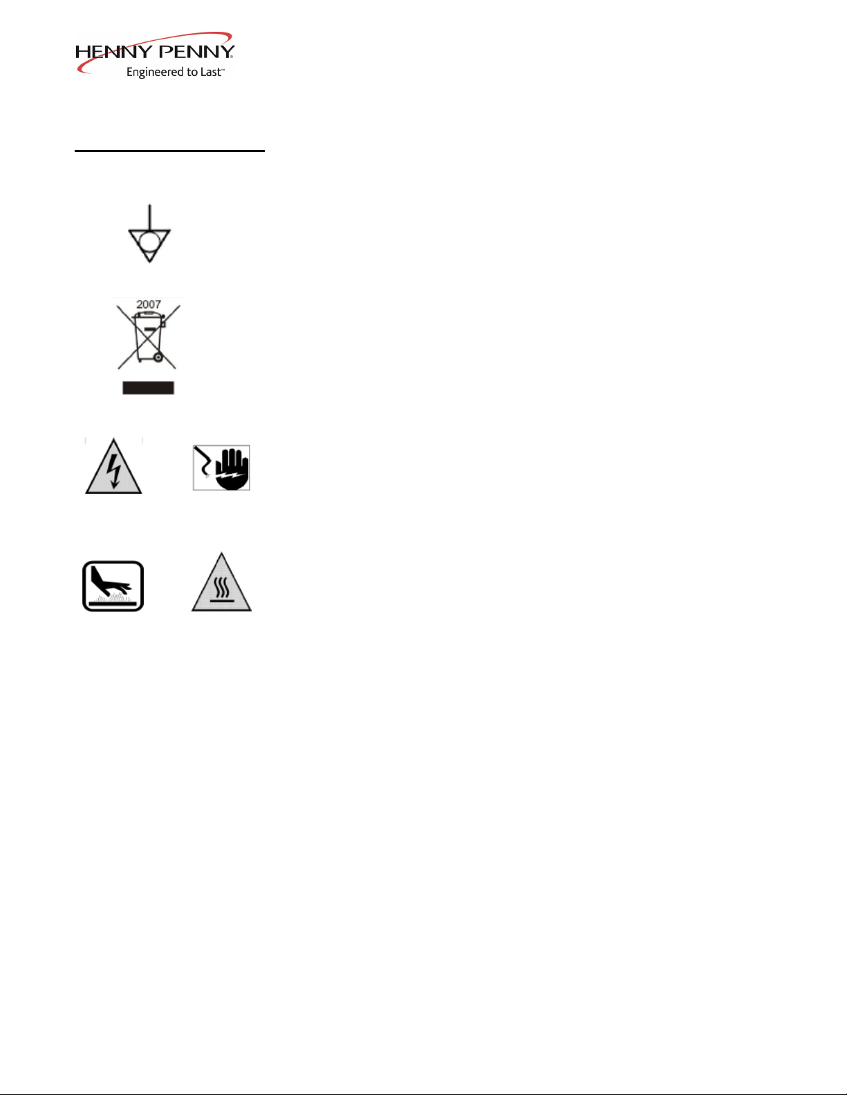
1-5. SAFETY (Continued)
Equipotential Ground Symbol
Waste Electrical and Electronic Equipment (WEEE) Symbol
Shock Hazard Symbols
or
Hot Surface Symbols
or
July 2011 1-3

Model OFE/OFG-321,322,323,324
Model OFE/OFG-321,322,323,324
SECTION 2. INSTALLATION
2-1. INTRODUCTION This section provides the installation instructions for
the Henny Penny Open Fryer.
Installation of the unit should be performed only by a
qualified service technician.
Do not puncture the unit with any objects such as
drills or screws as component damage or electrical
shock could result.
2-2. UNPACKING The Henny Penny Open Fryer has been tested, inspected, and
expertly packed to ensure arrival at its destination in the best
possible condition. The unit is banded to a wooden skid and
then packed inside a heavy cardboard carton with sufficient
padding to withstand normal shipping treatment.
Any shipping damage should be noted in the presence
of the delivery agent and signed prior to his or her
departure.
1. Carefully cut bands from cardboard carton.
2. Lift carton from the unit.
3. Cut and remove the metal bands holding the fryer to the
pallet.
4. Remove the fryer from the pallet.
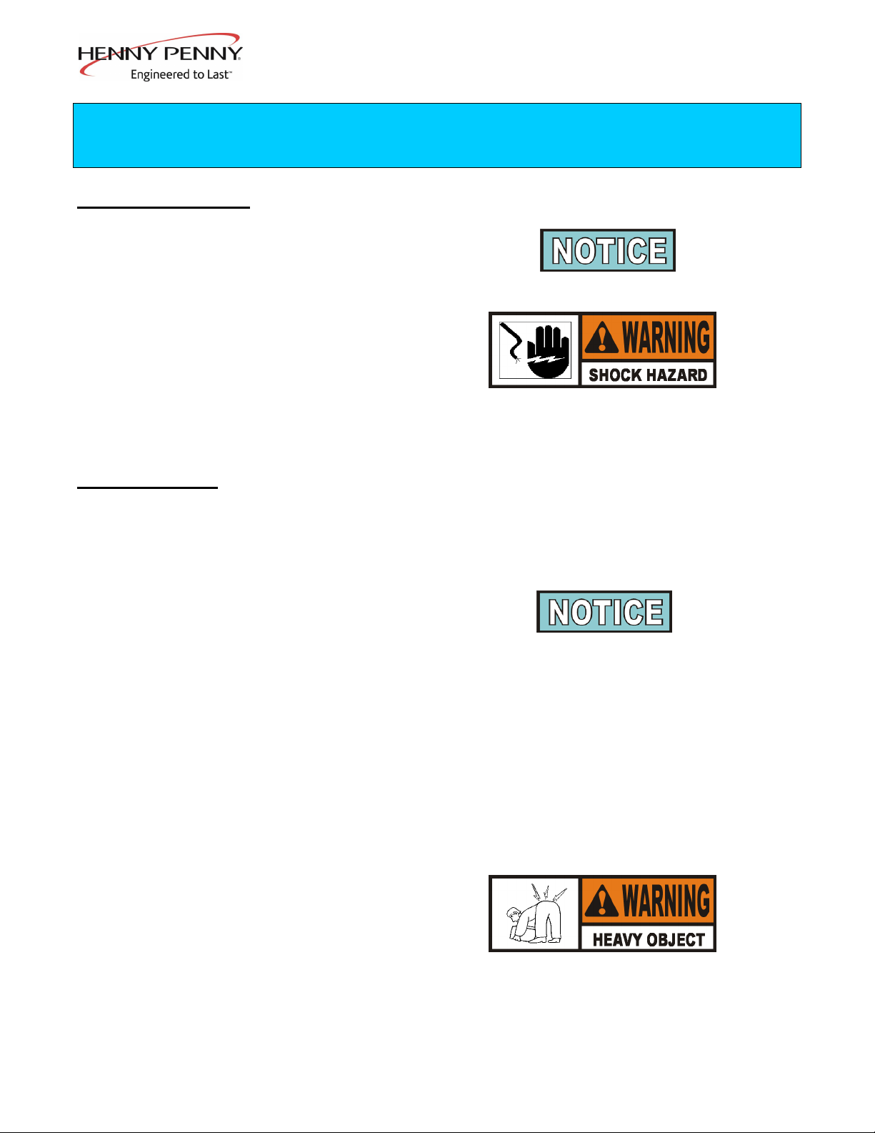
Take care when moving the fryer to prevent
personal injury. The fryer can weigh between
305 lbs. (138 kg) and 616 lbs. (279 kg).
July 2003 2-1
Model OFE/OFG-321,322,323,324
2-3. SELECTING THE The proper location of the open fryer is very important for
LOCATION the duration, speed, and convenience. The location of the
open fryer should allow clearances for servicing and proper
operation. Choose a location which will provide easy
loading and unloading without interfering with the final
assembly of food orders. Operators have found that frying
from raw to finish, and holding the product in warmers
provides fast continuous service. Keep in mind, the best
efficiency will be obtained by a straight line operation, i.e.,
raw in one side and finished out the other side. Order
assembly can be moved away with only a slight loss of
efficiency.
To prevent severe burns from splashing hot
shortening, position and install fryer to prevent
tipping or movement. Restraining ties may be used
for stabilization.
To avoid fire, install the open fryer with minimum
clearance from all combustible and noncombustible
materials, 4 inches (10.16 cm) from the side and 4
inches (10.16 cm) from the back. If installed properly,
the open fryer is designed for operation on combustible
floors and adjacent to combustible walls.
Do not spray aerosols in the vicinity of this appliance
while it is in operation.
2-4. LEVELING THE OPEN For proper operation, the open fryer should be level from
FRYER side to side and front to back. Using a level placed on the
flat areas around the frypot collar, on the middle well, adjust
the casters until the unit is level.
2-5. VENTILATION OF OPEN The open fryer should be located with provision for venting
FRYER into an adequate exhaust hood or ventilation system. This is
essential to permit efficient removal of the steam exhaust and
frying odors. Special precaution must be taken in designing
an exhaust canopy to avoid interference with the operation of
the open fryer. We recommend you consult a local
ventilation or heating company to help in designing an
adequate syste
2-2 Feb. 2011
Model OFE/OFG-321,322,323,324
Ventilation must conform to local, state, and national
codes. Consult your local fire department or building
authorities.
When installing the gas open fryer, do not attach an
extension to the gas flue exhaust stack. This may impair
proper operation of the burner, causing malfunctions
and possible negative back draft.
2-6. GAS SUPPLY The gas open fryer is factory available for either natural or
propane gas. Check the data plate inside the front door of the
cabinet to determine the proper gas supply requirements. The
minimum supply for natural gas is 7 inches water column
(1.7 kPa), and 10 inches water column (2.49 kPa) for propane.
Do not attempt to use any gas other than that specified
on the data plate. Incorrect gas supply could cause a fire
or explosion resulting in severe injuries and/or property
damage.
Please refer below for the recommended hookup of the fryer to
main gas line supply.
To avoid possible serious personal injury:
• Installation must conform with local, state, and national
codes, the American National Standard Z223.1-(the latest
edition) National Fuel Gas Code, and the local
municipal building codes. In Canada, installation must be
in accordance with Standard CAN/CSA B 149.1 &
Installation Codes - Gas Burning Appliances and local codes.
In Australia, in accordance with Australian Gas
Authority rules AS5601.1/2-2010.
June 2011 2-3
2-5. VENTILATION OF OPEN
FRYER
(Continued)

Model OFE/OFG-321,322,323,324
2-6. GAS SUPPLY • The fryer and its manual shutoff valve must be disconnected
(Continued) from the gas supply piping system during any pressure
testing of that system at test pressures in excess of ½ PSIG
(3.45 kPa) (34.5 mbar).
• The fryer must be isolated from the gas supply piping
system by closing its individual manual shutoff valve
during any pressure testing of the gas supply piping
system at test pressures equal to or less than ½ PSIG
(3.45 kPa) (34.5 mbar).
• A standard one inch (2.54 cm), black steel pipe and
malleable fittings should be used for gas service connections
for 3 well open fryers, 3/4 inch (1.91 cm) for 2 wells, and 1/2
inch (1.27 cm) for single wells.
• Do not use cast iron fittings.
• Although one inch (2.54 cm) size pipe is recommended for
3 wells, 3/4 inch (1.91 cm) for 2 wells, and 1/2 inch (1.27 cm)
for single wells, piping should be of adequate size and
installed to provide a supply of gas sufficient to meet the
maximum demand without undue loss of pressure between
the meter and the open fryer. The pressure loss in the piping
system should not exceed 0.3 in. water column (0.747 mbar).
Provisions should be made for moving the open fryer for
cleaning and servicing. This may be accomplished by:
1. Installing a manual gas shut off valve and a disconnect
union, or
2. Installing a heavy-duty design A.G.A. certified
connector. In order to be able to service this appliance,
which is provided with casters, a connector complying
with ANSI Z21.69 or CAN 1-6.l0m88 and a
quick-disconnect device, complying with ANSI Z21.41
or CAN 1-6.9m70, must be installed. It must also be
installed with restraining means to guard against
transmission of strain to the connector as specified in
the appliance manufacturer's instruction.
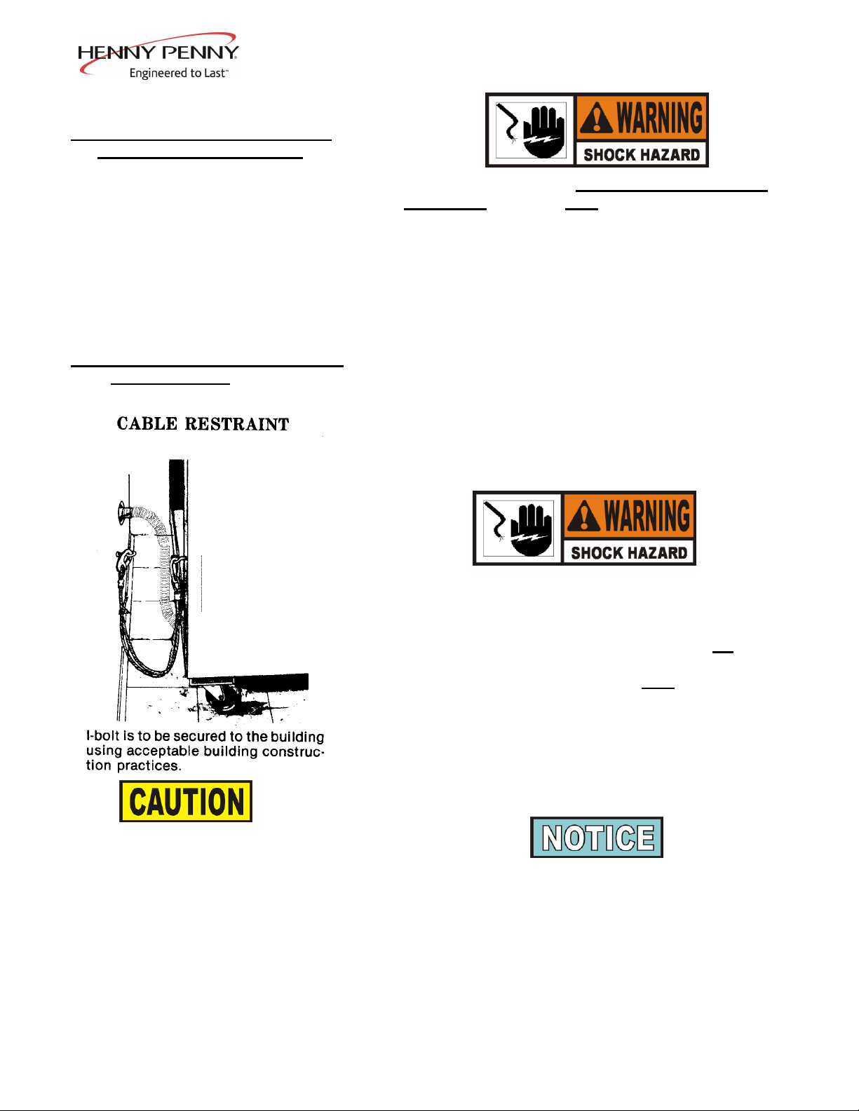
3. See the illustration on the following page for the proper
connection of flexible gas line and cable restraint.
The cable restraint limits the distance the open fryer can
be pulled from the wall. For cleaning and servicing the
unit, the cable must be unsnapped from the open fryer and
the flexible gas line disconnected. This will allow better
access to all sides of the open fryer. The gas line and
cable restraint must be reconnected once the cleaning or
servicing is complete.
2-4 July 2003
Model OFE/OFG-321,322,323,324
For Australia or New Zealand: Where a model is supplied with
castors and is to be connected to a fixed gas supply via a flexible hose
connection, a restraining chain or wire of adequate strength shall be
fixed to the appliance and be suitable to be fixed to the wall within 50
mm of each connection point. The length of the chain or wire shall not
exceed 80% of the length of the hose assembly.
Dec. 2016 2-5
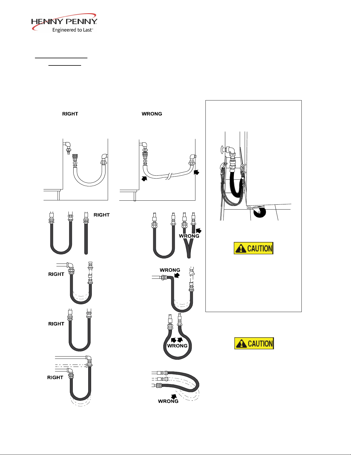
2-6. GAS SUPPLY
(Continued)
Couplings and hose should
be installed in the same
plane as shown at left. DO
NOT OFFSET
COUPLINGS -- this causes
torsional twisting and
undue strain causing
premature failure
This is the correct way to
install metal hose vor
vertical traverse. Note the
single, natural loop.
Allowing a sharp bend, as
shown at right, strains and
twists the metal hose to a
point of early failure at the
coupling
Maintain the minimum or
larger bending diameter
between the couplings for
longest lif e.
Closing in the diameter at
the coupling, as shown at
right, creates double bends
causing work work fatigue
failure of the f ittings.
In all installations where
“self-draining” is not
necessary, connect metal
hose in a vertical loop.
DO NOT CONNECT
METAL HOSE
HORIZONTALLY...unless
“self -draining” is necessary,
then use support on lower
plane as shown at lef t.
CABLE RESTRAINT
Please refer to the illustration below
when installing cable restraint on all
moveable gas fryers.
I-bolt is to be secured to the building
using acceptable building contruction
practices.
DRY WALL CONSTRUCTION
Secure I-bolt to a building stud DO
NOT attach to dry wall only. Also,
locate the I-bolt at teh same height as
the gas service. Preferred installation
is approximately six inches to either
side of service. Cable restraint must
be at least six inches shorter than
flexible gas line.
Utilize elbows when necesary to avoid
sharp kinks or excessive bending. For
ease of movement, install with a
“lazy” loop. gas appliance must be
disconnected prior to maximum
movement. (Minimum movement is
permissible for hose disconnection).
MINIMUM PULL of equipment
away from wall permissible
for accessibility to Quick
Disconnect Device
AVOID SHARP BENDSAND KINKS when
pulling equipment away from wall. (Maximum
pull will kink ends, even if installed properly,
and reduce Connector life.)
GAS PIPING
DISCONNECT
BEFORE
MAXIMUM PULL
MINIMUM PULL FOR
ACCESSIBILITY
ONLY
MAXIMUM PULL NOT
ADVISED WHILE
CONNECTED
QUICK DISCONNECT
DEVICE still attached
while extended at
maximum pull
STRESS
POINTS
STRESS
POINTS
12160004
Model OFE/OFG-321,322,323,324
Prior to turning the gas supply on, be sure the gas valve
knob on the gas control valve is in the OFF position.
Upon initial installation, and after moving the unit, the piping and
fittings should be checked for gas leaks. A simple checking
method is to turn on the gas and brush all connections with a soap
solution. If bubbles occur, it indicates escaping gas. In this event,
the piping connection must be redone.
To avoid fire or explosion, never use a lighted
match or open flame to test for gas leaks.
Ignited gas could result in severe personal
injury and/or property damage.
2-8. GAS PRESSURE REGULATOR The gas pressure regulator on the gas control valve is
SETTING factory set as follows:
• Natural: 3.5 inches water column (0.87 mbar).
• Propane 10.0 inches water column (2.49 mbar).
The gas pressure regulator has been set by Henny
Penny and is not to be adjusted by the user.
• 120 V, 50/60 Hz., 1 PH, 12 A
• 230 V, 50 Hz., 1 PH, 6 A
The 120 V gas open fryer requires a 3 wire grounded (earthed)
service and is supplied with a grounded cord and plug. Any 230
volt plug used on the 230 volt unit must conform to all local,
state, and national codes.
To avoid electrical shock, this appliance must be
equipped with an external circuit breaker which
incorporates a 3mm disconnection in all ungrounded
(unearthed) conductors. The main power switch on this
appliance does not disconnect all line conductors.
2-6 Dec. 2010
2-7. GAS LEAK TEST
2-9. ELECTRICAL REQUIREMENTS
OFG-320 SERIES
Model OFE/OFG-321,322,323,324
To avoid electrical shock, do not disconnect the ground
(earth) plug. This fryer must be adequately and
safely grounded (earthed). Refer to local electrical
codes for correct grounding (earthing) procedures or in
absence of local codes, with The National Electrical
Code, ANSI/NFPA No. 70-(the current edition). In
Canada, all electrical connections are to be made in
accordance with CSA C22.1, Canadian Electrical Code
Part 1, and/or local codes.
Refer to the table below for supply wiring and fusing.
(Per Well)
Volts Phase Kw Amps
200-208 3 14.4 40
220/240 3 14.4 40
440-480 3 14.4 17
380-415 3 14.4 20
To avoid electrical shock, this appliance must be
equipped with an external circuit breaker which will
disconnect all ungrounded (unearthed) conductors.
The main power switch on this appliance does not
disconnect all line conductors.
To avoid electrical shock, this fryer must be
adequately and safely grounded (earthed). Refer to
local electrical codes for correct grounding (earthing)
procedures or in absence of local codes, with The
National Electrical Code, ANSI/NFPA No. 70-(the
current edition). In Canada, all electrical connections are
to be made in accordance with CSA C22.1, Canadian
Electrical Code Part 1, and/or local codes.
CE units require a minimum wire size of 6 mm to be wired
to the terminal block.
Permanently connected electric fryers with casters must be
installed with flexible conduit and a cable restraint, when
installed in the United States. See illustration at left. Holes
are available in the rear fryer frame for securing the cable
restraint to the fryer. The cable restraint does not prevent
the fryer from tipping.
Dec. 2016 2-7
2-10. ELECTRICAL REQUIREMENTS
OFE-320 SERIES
2-9. ELECTRICAL REQUIREMENTS
OFG-320 SERIES (Continued)
DRYWALL CONSTRUCTION
Secure I-bolt to a building stud. Do
not attach to drywall only. Preferred
installation is approximately six
inches to either side of service.
Cable restraint must be at least six
inches shorter than flexible conduit.

Model OFE/OFG-321,322,323,324
Additional CE Electrical Statements:
The supply power cords shall be oil-resistant,
sheathed flexible cable, no lighter than ordinary
polychloroprene or other equivalent synthetic
elastomer-sheathed cord, and must be HO7RN type.
It is recommended that a 30 mA rated protective
device such as a residual current circuit breaker
(RCCB), or ground fault circuit interrupter (GFCI),
be used on the fryer circuit.
(FOR EQUIPMENT WITH CE MARK ONLY!)
To prevent electric shock hazard this appliance
must be bonded to other appliances or touchable
metal surfaces in close proximity to this
appliance with an equipotential bonding
conductor. This appliance is equipped with an
equipotential lug for this purpose. The
equipotential lug is marked with the following
symbol .
2-8 July 2011
2-10. ELECTRICAL REQUIREMENTS
OFE-320 SERIES (Continued)

Model OFE/OFG-321,322,323,324
2-11. TESTING THE FRYER Each Henny Penny pressure fryer was completely checked
and tested prior to shipment. However, it is good practice to
check the unit for proper operation.
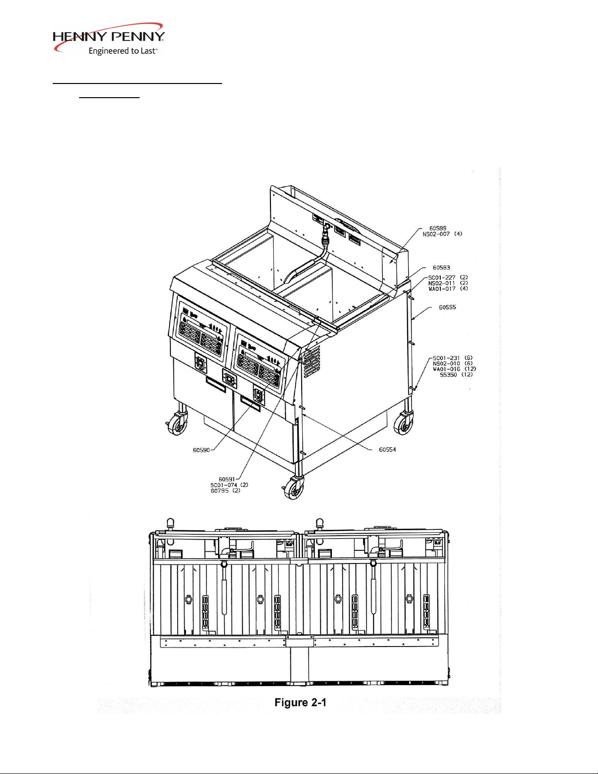
2-12. JOINING INSTRUCTIONS The following instructions are for joining two units together.
The instructions have part numbers in them. Please refer to
figure 2-1 on the following page to visually match the
numbers in the instructions below to the illustration.
1. Remove all hardware from the sides of the two open
fryers.
2. Remove the right control panel assembly from the left
unit and the left control panel assembly from the right
unit.
3. Move the two units side by side with minimal gap.
4. Remove the right front caster from the left unit and the
left rear caster from the right unit. Fasten both casters to
the rear of the unit with wire ties (EF02-041).
5. Position the two open fryers by inserting bolts
(SC01-227) thru the holes in top cover and the pot sides.
Use washer (WA01-017) on both sides of the bolt when
installing. DO NOT TIGHTEN!
6. Position front spacer (60554) between the front of the two
open fryers. Place bolt (SC01-231), backed by washers
(55350 & WA01-016), thru three holes in the frame
capturing the spacer between the frames. Place washers
(55350 & WA01-016) on bolt before installing nuts
(NS02-010). DO NOT TIGHTEN!
7. Repeat with rear spacer (60555).
8. Tighten all fasteners securely.
9. Place cover (60593) over gap between open fryers.
10. Drill out dimples on rear shroud to 0.250 diameter holes.
11. Apply silicon around edge of unfinished side of rear
cover (60599). Install rear cover (60599) with #8 nuts
(NS02-007).
2-9 Feb. 2011
Model OFE/OFG-321,322,323,324
2-12. JOINING INSTRUCTIONS 12. Apply silicon around edge of unfinished side of top cover
(Continued) (60590) and basket rest cover (60591). Position top cover
(60590) on open fryer top cover and install basket rest
cover (60591) using #10 screws and nuts (SC01-074 &
60795).
13. Apply silicon to any gaps that may be left.
Oct. 2005 2-10

Model OFE/OFG-321,322,323,324
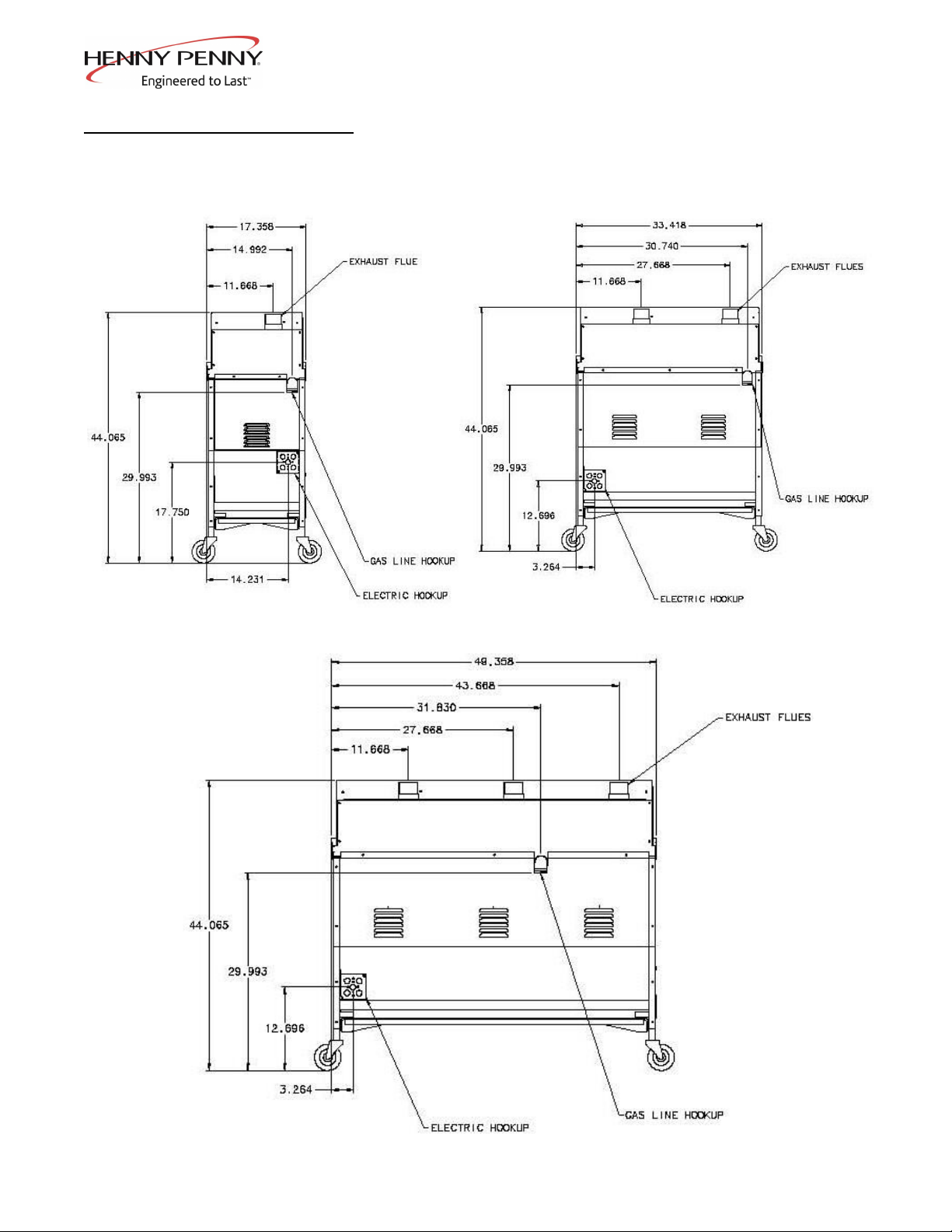
2-13. DIMENSIONS
Feb. 2011 2-11
OFX-321
OFX-322
OFX-323
Model OFE/OFG-321,322,323,324
2-13. DIMENSIONS (Continued)
2-12 Feb. 2011
OFG-321
OFG-322
OFG-32X Flue & Gas Line Dimensions
(All views are from rear of fryers)
OFG-323

Model OFE/OFG-321,322,323,324
SECTION 3. OPERATION
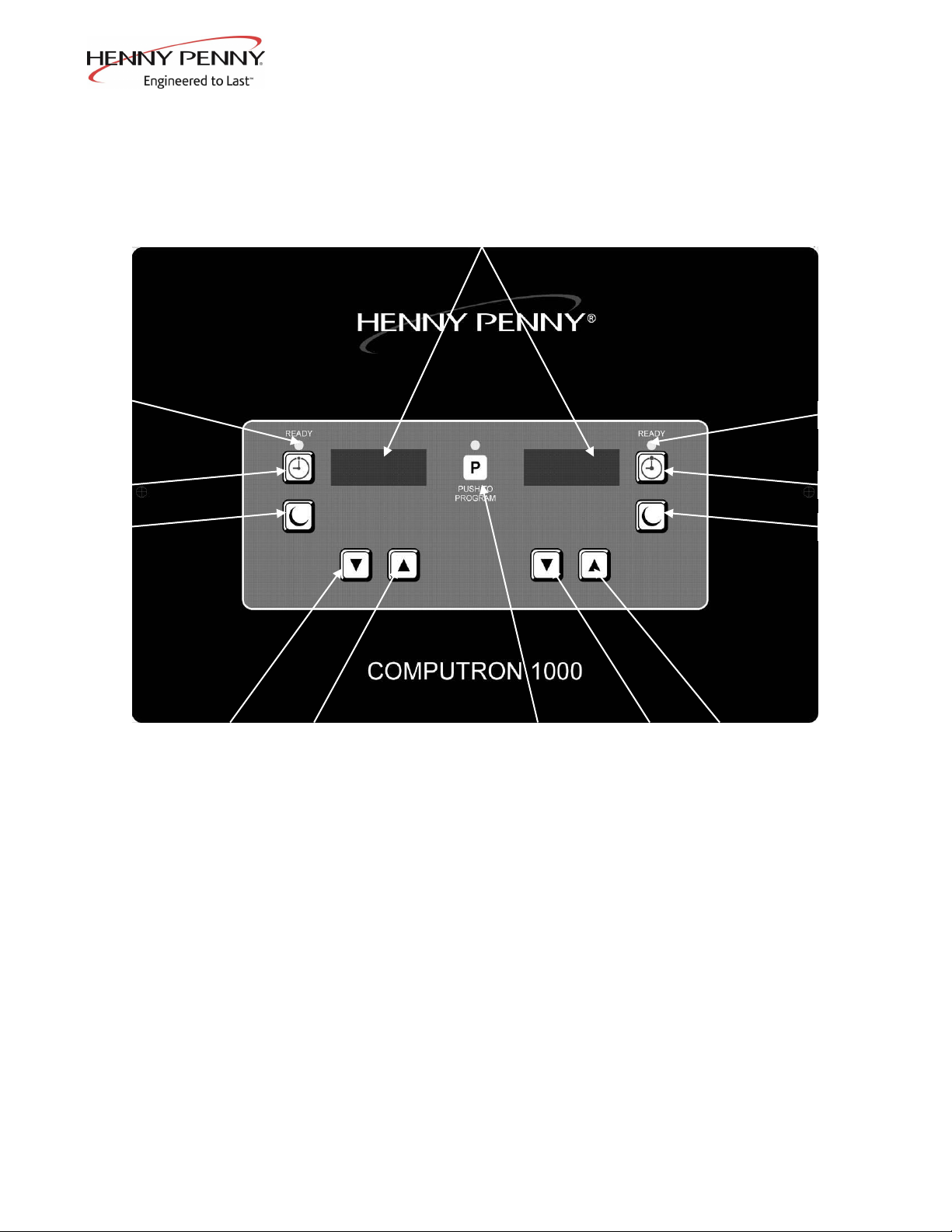
3-1. OPERATING COMPONENTS Reference Figure 3-1.
C1000 CONTROLS
Fig. Item Description Function
No. No.
3-1 1 Digital Display Shows the shortening temperature, the timer countdown in
the Cook Cycle, and the selections in the Program Mode; the
temperature of the shortening can be shown by pressing
once, or twice to view set-point temperature;
if shortening temperature exceeds 425F (218C), the display
reads “E-5, FRYER TOO HOT”
3-1 2 This LED lights when the shortening temperature is within 5
of the setpoint temperature, signaling the operator that the
shortening temperature is now at the proper temperature for
dropping product into the frypot
3-1 3 The timer buttons are used to start and stop Cook Cycles
3-1 4 The idle buttons are used to start an Idle Mode which reduces
the temperature of the shortening during non-use periods;
press and hold to exit the Idle Mode
3-1 5 The program button is used to access the Program Modes;
also, once in the Program Mode, it is used to advance to the
next parameter
3-1 6 & 7 Used to adjust the value of the currently displayed setting
in the Program Mode and to change set-point temperature for the left frypot, or basket
3-1 8 & 9 Used to adjust the value of the currently displayed setting
in the Program Mode and to change set-point temperature for the right frypot, or basket
Proceed onto Section 3-4, Filling or Adding Shortening
Jan. 2008
3-1
Model OFE/OFG-321,322,323,324
Figure 3-1
3-2 Jan. 2008
6
7
5
8
9
Model OFE/OFG-321,322,323,324
3-2. OPERATING COMPONENTS Figure 3-2 shows the function of the 12 button timer control,
6 & 12 BUTTON CONTROLS and Figure 3-3 shows the function of the 6 button timer control.
Fig. Item Description Function
No. No.
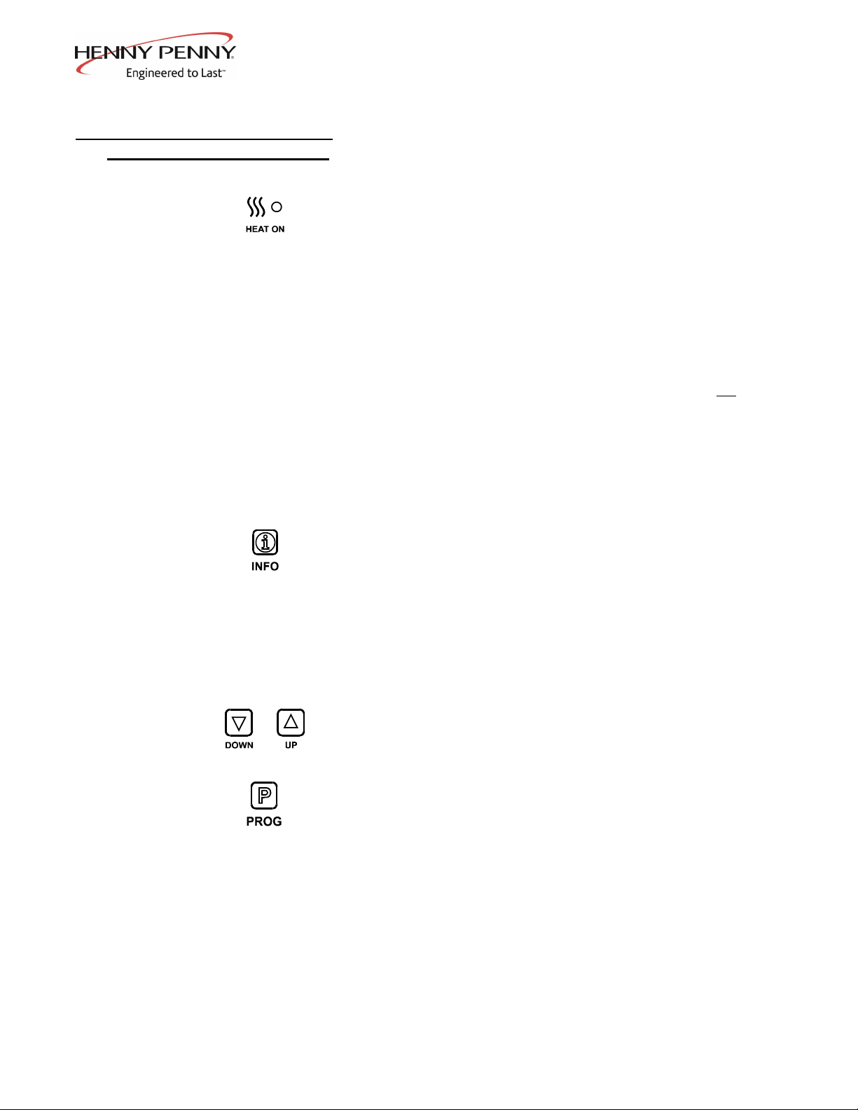
3-1 1 This LED lights when the control calls for heat,
3-2 and the burners come on and heat the shortening
3-1 2 Digital Displays Shows the shortening temperature, the timer countdown in
3-2 the Cook Cycle, and the selections in the Program Mode; the
temperature of the shortening can be shown by depressing
the INFO button; if the temperature exceeds 425F (218C),
the display reads “E-5, FRYER TOO HOT”
3-1 3 WAIT LED Once the open fryer is out of the Melt Cycle, this LED lights,
3-2 signaling the operator that the shortening temperature is not at the
proper temperature for dropping product into the frypot
3-1 4 READY LED This LED lights when the shortening temperature
3-2 is within 5 of the setpoint temperature, signaling the
operator that the shortening temperature is now at the proper
temperature for dropping product into the frypot
3-1 5 Press to display the following fryer information and status:
3-2 a. The temperature of the shortening
b. The temperature setpoint
c. Filter status
d. The number of times filtered today
e. The average no. of filters per day
f. No. of times Cook Cycle was stopped early today
g. No. of times Cook Cycle was stopped early in past week
e. Date and time
3-1 6 & 7 Used to adjust the value of the currently displayed setting
3-2 in the Program Mode
3-1 8 Used to access the Program Modes; also, once in the
3-2 Program Mode, it is used to advance to the next parameter
3-1 9 START/STOP Used to start and stop Cook Cycles; also de-activates
3-2 Button the quality timer at the end of a Hold Mode
3-1 10 Menu Card Displays the food product associated with each product
3-2 Window selection button below; the menu card strip is located
behind the decal
3-1 11 Product Select Used to select which food products are to be cooked
3-2 Buttons (on auto-lift open fryers, the 6 and 12 product buttons are basket
lift buttons)
Oct. 2005 3-3
 Loading...