


OPERATOR’S
M A N U A L
WENDY’S EVOLUTION ELITE™ (Gas)
REDUCED OIL CAPACITY OPEN FRYER
MODEL
EEG-253
EEG-254
R E G I S T E R WA R R A N T Y O N L I N E AT W W W. H E N N Y P E N N Y. C O M
This manual should be retained in a convenient location for future reference.
A wiring diagram for this appliance is located on the inside of the door.
Post in a prominent location, instructions to be followed in event user smells gas. This information shall be obtained by consulting the local gas supplier.
Do not obstruct the flow of combustion and ventilation air.Adequate clearance must be left all around appliance for sufficient air to the combustion chamber.
The Model EEG-10X open fryer is equipped with a continuous pilot. But the open fryer cannot be operated without electric power, and no attempt should be made to operate the fryer during a power outage. The unit will automatically return to normal operation when power is restored.
To avoid a fire, keep appliance area free and clear from combustibles.
Improper installation, adjustment, alteration, service, or maintenance can cause property damage, injury, or death. Read the installation, operating, and maintenance instructions thoroughly before installing or servicing this equipment.
DO NOT STORE OR USE GASOLINE OR OTHER FLAMMABLE VAPORS AND LIQUIDS IN THE VICINITY OF THIS OR ANY OTHER APPLIANCE. FIRE OR EXPLOSION COULD RESULT.
|
Technical Data for CE/AGA Marked Products |
Nominal Heat Input: |
Natural (I2H) = 19,8, kW (67,560 Btu/h) |
(Net) |
Natural (I2E) = 19.8 kW (67,560 Btu/h) |
|
Natural (I2E+) = 19.8 kW (67,560 Btu/h) |
|
Natural (I2L) = 19.8 kW (67,560 Btu/h) |
|
Natural (I2HS) = 19.8 kW (67,560 Btu/h) |
|
Liquid Propane (I3P) = 19,8, kW (67,560 Btu/h) |
Nominal Heat Input: |
Natural (I2H) = 21,98 kW (75,000 Btu/h) (79.13 MJ/h) |
(Gross) |
Natural (I2E) = 21,98 kW (75,000 Btu/h) |
|
Natural (I2E+) = 21,98 kW (75,000 Btu/h) |
|
Natural (I2L) = 21,98 kW (75,000 Btu/h) |
|
Natural (I2HS) = 21,98 kW (75,000 Btu/h) |
|
Liquid Propane (I3P) = 21,98 kW (75,000 Btu/h) (79.13 MJ/h) |
Supply Pressure: |
Natural (I2H) = 20 mbar (2.0 kPa) |
|
Natural (I2E) = 20 mbar |
|
Natural (I2E+) = 20/25 mbar |
|
Natural (I2L) = 25 mbar |
|
Natural (I2HS) = 25 mbar |
|
Liquid Propane (I3P) = 30/37/50 mbar (3.0/3.7/5.0 kPa) |
Test Point Pressure: |
Natural (I2H) = 8.7 mbar (.87 kPa) |
|
Natural (I2E) = 8,7 mbar |
|
Natural (I2E+) = N/A |
|
Natural (I2L) = 8.7 mbar |
|
Natural (I2HS) = 8.7 mbar |
|
Liquid Propane (I3P) = 25 mbar (2.5 kPa) |
Injector Size: |
Natural (I2H) = 2.08 mm |
|
Natural (I2E) = 2.08 mm |
|
Natural (I2E+) = 1.70 mm |
|
Natural (I2L) = 2.30 mm |
|
Natural (I2HS) = 2.30 mm |
|
Liquid Propane (I3P) = 1.30 mm |
This appliance must be installed in accordance with the manufacturer’s instructions and the regulations in force and only used in a suitable ventilated location. Read the instructions fully before installing or using the appliance.
Noise generated from this equipment is less than 70 dB(A)

|
TABLE OF CONTENTS |
|
INTRODUCTION................................................................................................................ |
1 |
|
1-1 |
Safety.................................................................................................................... |
1 |
1-2 |
Introduction.......................................................................................................... |
3 |
1-3 |
Features................................................................................................................ |
3 |
1-4 |
Proper Care........................................................................................................... |
3 |
1-5 |
Assistance............................................................................................................. |
3 |
INSTALLATION.................................................................................................................. |
5 |
|
2-1 |
Introduction.......................................................................................................... |
5 |
2-2 |
Unpacking............................................................................................................ |
5 |
2-3 |
Selecting the Fryer Location................................................................................ |
6 |
2-4 |
Leveling the Fryer................................................................................................ |
6 |
2-5 |
Ventilation of Fryer.............................................................................................. |
6 |
2-6 |
Gas Supply........................................................................................................... |
7 |
2-7 |
Gas Leak Test..................................................................................................... |
10 |
2-8 |
Gas Pressure Regulator Setting.......................................................................... |
10 |
2-9 |
Electrical Requirements..................................................................................... |
10 |
2-10 |
Motor Bearings................................................................................................... |
11 |
2-11 |
Lighting and Shutdown of the Burners.............................................................. |
11 |
2-12 |
Testing the Fryer................................................................................................. |
11 |
2-13 |
Dimensions......................................................................................................... |
12 |
OPERATION...................................................................................................................... |
15 |
|
3-1 |
Operating Components....................................................................................... |
15 |
3-2 |
Set-Up Mode...................................................................................................... |
19 |
3-3 |
Filling or Adding Oil.......................................................................................... |
20 |
3-4 |
Morning Start-Up Procedures............................................................................ |
21 |
3-5 |
Basic Operation.................................................................................................. |
22 |
3-6 |
Idle Mode........................................................................................................... |
22 |
3-7 |
Oil Guardian™ (Auto Top-Off)......................................................................... |
23 |
3-8 |
Selecting a Product with a Different Setpoint.................................................... |
23 |
3-9 |
Replacing the BIB.............................................................................................. |
23 |
3-10 |
Filter - Smart Touch........................................................................................... |
24 |
3-11 |
Auto Daily Filtering........................................................................................... |
26 |
3-12 |
Discarding Oil from Vat Using Optional Discard Shuttle.................................. |
28 |
3-13 |
Discarding Oil from Vat Using Optional Bulk Oil Dispose System.................. |
29 |
3-14 |
Discarding Oil Using Optional Oil Discard Shuttle - ODS-400........................ |
30 |
3-15 |
Discarding Oil Using Optional Oil Discard Shuttle - ODS-450........................ |
33 |
3-16 |
Changing the Filter Pad...................................................................................... |
36 |
3-17 |
Removing and Cleaning Basket Rest................................................................. |
39 |
3-18 |
Clean-Out Mode - Smart Touch......................................................................... |
39 |
3-19 |
Coldsoak Procedure........................................................................................... |
42 |
3-20 |
Check/Replace Filter Drain Pan O-Rings.......................................................... |
43 |
3-21 |
Info Button Stats................................................................................................ |
44 |
3-22 |
Filter Button Stats.............................................................................................. |
44 |
3-23 |
Preventive Maintenance Schedule..................................................................... |
45 |
3-24 |
Clean Blower & Vents........................................................................................ |
46 |
INFORMATION MODE.................................................................................................... |
47 |
|
4-1 |
Information Mode Details.................................................................................. |
47 |
March 2017 |
i |

PRODUCT PROGRAM MODE........................................................................................ |
53 |
|
5-1 |
Modifying Product Settings............................................................................... |
53 |
LEVEL 2 PROGRAMMING............................................................................................. |
57 |
|
6-1 |
Special Program Mode....................................................................................... |
59 |
6-2 |
Do Not Disturb................................................................................................... |
65 |
6-3 |
Clock Set............................................................................................................ |
66 |
6-4 |
Data Logging, Heat Control, Tech, Stat, and Filter Control Mode.................... |
66 |
TROUBLESHOOTING..................................................................................................... |
67 |
|
7-1 |
Troubleshooting Guide....................................................................................... |
67 |
7-2 |
Error Codes........................................................................................................ |
69 |
March 2017 |
ii |
SECTION1:INTRODUCTION
1-1 SAFETY
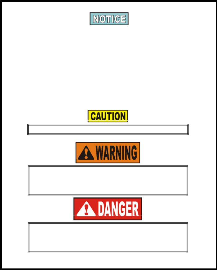
The instructions in this manual have been prepared to aid you in learning the proper procedures for your equipment. Where information is of particular importance or is safety related, the words NOTICE, CAUTION, or WARNING are used. Their usage is described below.
If a problem occurs during the first operation of a new unit, recheck the Installation Section of the Operator’s Manual.
Before troubleshooting, always recheck the Operation
Section of the Operator’s Manual.
Where information is of particular importance or is safety related, the words DANGER, WARNING, CAUTION, or NOTICE are
used. Their usage is described as follows:
SAFETYALERT SYMBOL is used with DANGER,
WARNING or CAUTION which indicates a personal injury type hazard.
NOTICE is used to highlight especially important information.
CAUTION used without the safety alert symbol indicates a potentially hazardous situation which, if not avoided, may result in property damage.
CAUTION used with the safety alert symbol indicates a potentially hazardous situation which, if not avoided, could result in minor or moderate injury.
WARNING indicates a potentially hazardous situation which, if not avoided, could result in death or serious injury.
DANGER INDICATES AN IMMINENTLY HAZARDOUS SITUATION WHICH, IF NOT AVOIDED, WILL RESULT IN DEATH OR SERIOUS INJURY.
March 2017 |
1 |
1-1. SAFETY (CONT.)
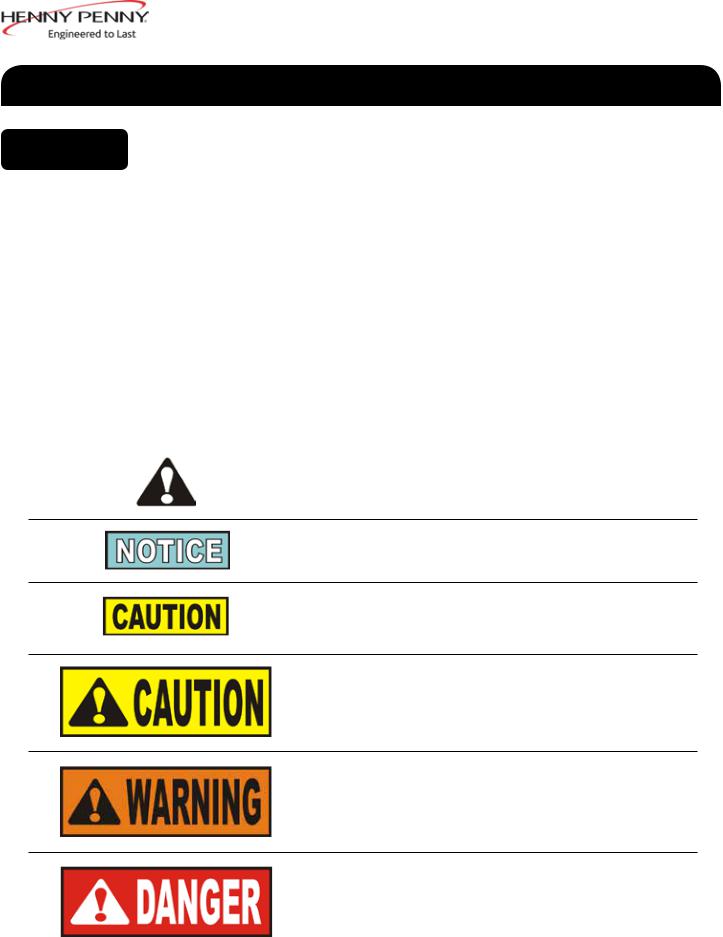
Equipotential Ground Symbol
Waste Electrical and Electronic Equipment (WEEE) Symbol
OR |
Shock Hazard Symbols |
OR |
Hot Surface Symbols |
Aug. 2013 |
2 |

1-2. INTRODUCTION
1-3. FEATURES
1-4. PROPER CARE
1-5. ASSISTANCE
The Henny Penny open fryer is a basic unit of food processing equipment designed to cook foods better and easier. The micro computer-based design helps make this possible. This unit is used only in institutional and commercial food service operations, and operated by qualified personnel.
•As of August 16, 2005, the Waste Electrical and Electronic
Equipment directive went into effect for the European Union. Our products have been evaluated to the WEEE directive. We have also reviewed our products to determine if they comply with the Restriction of Hazardous Substances directive (RoHS) and have redesigned our products as needed in order to comply. To continue compliance with these directives, this unit must not be disposed as unsorted municipal waste. For proper disposal, please contact your nearest Henny Penny distributor.
•Easily cleaned
•Uses 40% less oil
•Full vat or split vat
•Computer control
•Stainless steel construction
•Automatic oil top off
•Self-diagnostic system built into controls
•Built in filter with automatic filtration
•Propane or natural gas; 75,000 BTU/vat (21.97 kw)
As in any unit of food service equipment, the Henny Penny
open fryer does require care and maintenance. Requirements for the maintenance and cleaning are contained in this manual and must become a regular part of the operation of the unit at all times.
Contact a qualified service technician in case of major maintenance or repairs to the unit.
Should you require outside assistance, call your local independent distributor in your area, or call Henny Penny Corp. at 1-800-417-8405 or 1-937-456-8405.
Aug. 2013 |
3 |
|
SECTION 2: INSTALLATION |
2-1. |
This section provides the installation and unpacking instructions for the |
INTRODUCTION |
Henny Penny Evolution Elite® fryer. |
Installation of this unit should be performed only by a qualified service technician.
Do not puncture the fryer with any objects such as drills or screws as component damage or electrical shock could result.
2-2. UNPACKING
Any shipping damage should be noted in the presence of the delivery agent and signed prior to his or her departure.
1.Cut and remove the metal bands from the carton.
2.Remove carton lid and lift the main carton off the fryer.
3.Remove corner packing supports (4).
4.Cut the stretch film from around the carrier/rack box and remove it from the top of the fryer lid.
5.Cut and remove the metal bands holding the fryer to the pallet, and remove fryer from pallet.
Remove filter drain pan and BIB shelf from fryer before removing fryer from pallet or damage to the unit could result. Figure 1.
Take care when moving the fryer to prevent personal injury. The fryer weighs approximately 600 lbs. (272 kg) to 800 lbs. (363 kg).
Aug. 2013 |
5 |
2-3. SELECTING THE FRYER LOCATION
2-4. LEVELING THE FRYER
2-5. VENTILATION OF FRYER
The proper location of the fryer is very important for operation, speed, and convenience. The location of the open fryer should allow clearances for servicing and proper operation. Choose a location which will provide easy loading and unloading without interfering with the final assembly of food orders. Operators have found that frying from raw to finish, and holding the product in warmers provides fast continuous service. Keep in mind, the best efficiency will be obtained by a straight line operation, i.e. raw in one side and finished out the other side. Order assembly can be moved away with only a slight loss of efficiency.
To avoid fire, install the open fryer with minimum clearance from all combustible materials, 2 inches (5.08 cm) from the side and 4 inches (10.16 cm) from the back. Minimum clearance from all non-combustible materials, 0 inches (0.00 cm) from the side and 0 inches (0.00 cm) from the back. If installed properly, the open fryer is designed for operation on non-
combustible floors only
Do not spray aerosols in the vicinity of this appliance while it is in operation.
To prevent severe burns from splashing hot oil, position and install fryer to prevent tipping or movement. Restraining ties may be used for stabilization.
For proper operation, the open fryer should be level from side-to-side and front to back. Using a level placed on the flat areas around the vat collar, on the middle well, and then adjust the casters until the unit is level.
The fryer should be located with provision for venting into an adequate exhaust hood or ventilation system. This is essential to permit efficient removal of the steam exhaust and frying odors. Special precaution must be taken in designing an exhaust canopy to avoid interference with the operation of the fryer. We recommend you consult a local ventilation or heating company to help in designing an adequate system.
Ventilation must conform to local, state, and national codes. Consult your local fire department or building authorities.
Aug. 2013 |
6 |
2-6. GAS SUPPLY
When installing the gas open fryer, do not attach an extension to the gas flue exhaust stack. This may impair proper operation of the burner, causing malfunctions and possible negative back draft.
The gas open fryer is factory available for either natural or propane gas. Check the data plate inside the left front door of the cabinet to determine the proper gas supply requirements. The minimum supply for natural gas is 7 inches water column (1.7 kPa) (17.0 mbar), and 10 inches water column (2.49 kPa) (24.9 mbar) for propane.
Do not attempt to use any gas other than that specified on the data plate. Incorrect gas supply could cause a fire or explosion resulting in severe injuries and/or property damage.
Please refer below for the recommended hookup of the fryer to main gas line supply.
To avoid possible serious personal injury:
•Installation must conform with local, state, and national
codes, the American National Standard Z223.1/NFPA 54 -(the latest edition) National Fuel Gas Code, and the local municipal building codes. In Canada, the Natural
Gas and Propane Installation Code is CSA B149.1 & Installation Codes - Gas Burning Appliances and local codes. In Australia, in accordance with Australian Gas Authority rules AS5601.1/2-2010.
•The fryer and its manual shutoff valve must be disconnected from the gas supply piping system during any pressure testing of that
system at test pressures in excess of 1/2 PSIG (3.45 kPa) (34.5 mbar).
•The fryer must be isolated from the gas supply piping system by closing its individual manual shutoff valve during any pressure testing of the gas supply piping
system at test pressures equal to or less than 1/2 PSIG (3.45 kPa) (34.5mbar).
•A standard one inch (2.54 cm), black steel pipe and
malleable fittings should be used for gas service connections for 3 & 4 well open fryers, and 3/4 inch (1.91 cm) for 2 wells.
•Do not use cast iron fittings.
•Although one inch (2.54 cm) size pipe is recommended for 3 & 4 wells and 3/4 inch (1.91 cm) for 2 wells, piping should be of adequate size and installed to provide a supply of gas sufficient to meet the maximum demand without undue loss of pressure between the meter and the open fryer. The pressure loss in the piping system should not exceed 0.3 in. water column (0.747 mbar).
Aug. 2013 |
7 |
2-6. GAS SUPPLY
(CONT.)
Provisions should be made for moving the open fryer for cleaning and servicing. This may be accomplished by:
1.Installing a manual gas shutoff valve and a disconnect or union.
2.Installing a heavy-duty design CSAcertified connector. In order to be able to service this appliance, which is provided with casters, a connector complying with ANSI Z21.69-CAN 6.16 or CAN
1-6.10m88 and a quick-disconnect device, complying withANSI
Z21.41or CAN 1-6.9m70, must be installed. It must also be installed with restraining means to guard against transmission of strain to the connector as specified in the appliance manufacturer’s instructions.
3.See the illustration on the following page for the proper connection of flexible gas line and cable restraint.
The cable restraint limits the distance the open fryer can be pulled from the wall. For cleaning and servicing the unit, the cable must be unsnapped from the open fryer and the flexible gas line disconnected. This allows better access to all sides of the open fryer. The gas line and cable restraint must be reconnected once the cleaning or servicing is complete.
Aug. 2013 |
8 |

2-6. GAS SUPPLY
(CONT.)
GAS PIPING
MINIMUM PULL of equipment away from wall permissible for accessibility to Quick Disconnect Device
DISCONNECT |
BEFORE |
MAXIMUM PULL |
MINIMUM PULL FOR |
ACCESSIBILITY |
ONLY |
AVOID SHARP BENDS AND KINKS when pulling equipment away from wall. (Maximum pull will kink ends, even if installed properly, and reduce Connector life.)
QUICK DISCONNECT DEVICE still attached while extended at maximum pull
STRESS STRESS
POINTS POINTS
MAXIMUM PULL NOT
ADVISED WHILE
CONNECTED
Couplings and hose should be installed in the same plane as shown at left. DO NOT OFFSET COUPLINGS -- this causes torsional twisting and undue strain causing premature failure
This is the correct way to

 install metal hose vor
 vertical traverse. Note the


 single, natural loop.
 Allowing a sharp bend, as shown at right, strains and
  twists the metal hose to a
point of early failure at the coupling
Maintain the minimum or larger bending diameter between the couplings for longest life.
Closing in the diameter at the coupling, as shown at right, creates double bends causing work work fatigue failure of the fittings.
In all installations where


 “self-draining” is not
necessary, connect metal
hose in a vertical loop. DO NOT CONNECT METAL HOSE HORIZONTALLY...unless
“self-draining” is necessary,
then use support on lower plane as shown at left.
CABLE RESTRAINT
Please refer to the illustration below when installing cable restraint on all moveable gas fryers.
I-bolt is to be secured to the building using acceptable building contruction practices.
DRY WALL CONSTRUCTION
Secure I-bolt to a building stud DO NOT attach to dry wall only. Also, locate the I-bolt at teh same height as the gas service. Preferred installation is approximately six inches to either side of service. Cable restraint must be at least six inches shorter than flexible gas line.
Utilize elbows when necesary to avoid sharp kinks or excessive bending. For ease of movement, install with a “lazy” loop. gas appliance must be disconnected prior to maximum movement. (Minimum movement is permissible for hose disconnection).
12160004
Dec. 2016 |
9 |

2-7.
GAS LEAK TEST
2-8.
GAS PRESSURE REGULATOR
SETTING
2-9. ELECTRICAL REQUIREMENTS
Prior to turning the gas supply on, be sure the gas valve knob on the gas control valve is in the off position.
Upon initial installation, and after moving the unit, the piping and fittings should be checked for gas leaks. A simple checking method is to turn on the gas and brush all connections with a soap solution. If bubbles occur, it indicates escaping gas. In this event, the piping connection must be redone.
To avoid fire or explosion, never use a lighted match or open flame to test for gas leaks. Ignited gas could result in severe personal injury and/ or property damage.
The gas pressure regulator on the gas control valve is factory set as follows:
•Natural: 3.5 inches water column (0.87 kPa) (8.72 mbar).
•Propane 10.0 inches water column (2.49 kPa) (24.9 mbar).
The gas pressure regulator has been set by Henny Penny and is not to be adjusted by the user.
•120 V, 50/60 Hz, 1 PH, 12A
•230 V, 50 Hz, 1 PH, 7 A
The 120 volt gas fryer is factory equipped with a grounded (earthed) cord and plug for your protection against shock, and should be plugged into a three-prong grounded (earthed) receptacle. Do not cut or remove grounding (earthing) prong. Any 230 volt plug used on the 230 volt unit must conform to all local, state, and national codes.
To avoid electrical shock, this appliance must be equipped with an external circuit breaker which incorporates a 3mm disconnection in all ungrounded (unearthed) conductors. The main power switch on this appliance does not disconnect all line conductors.
Aug. 2013 |
10 |
2-9. ELECTRICAL REQUIREMENTS (CONT.)
2-10.
MOTOR BEARINGS
2-11. LIGHTING AND SHUTDOWN OF THE BURNERS
2-12. TESTING THE FRYER
To avoid electrical shock, do not disconnect the ground (earth) plug. This fryer must be adequately and safely grounded (earthed). Refer to local electrical codes for correct grounding (earthing) procedures or in absence of local codes, with The National Electrical Code, ANSI/
NFPA No. 70-(the current edition). In Canada, all electrical connections are to be made in accordance with CSA C22.2, Canadian Electrical Code Part 1, and/or local codes.
Disconnect power supply before a thorough cleaning or servicing the fryer.
The electric motor bearings are permanently lubricated. DO NOT
LUBRICATE.
1.Turn the power switch to the OFF position.
2.Wait at least 5 minutes and then turn power switch to the ON position.
3.Press  button on the controls (left or right).
4.The burner lights and operates in a Melt Cycle until the shortening reaches a preset temperature.
5.Once the display shows a product selection or a double dashes, press the desired product button.
The fryer is equipped with a ignition spark module which has a set ignition safety time (TSA) of 90 seconds.
To shutdown burner:
1.Press  button on the controls (left or right).
2.Turn the power switch to the OFF position. NOTE: This turns off all vats.
Each Henny Penny open fryer was completely checked and tested prior to shipment. However, it is good practice to check the unit for proper operation.
Aug. 2013 |
11 |
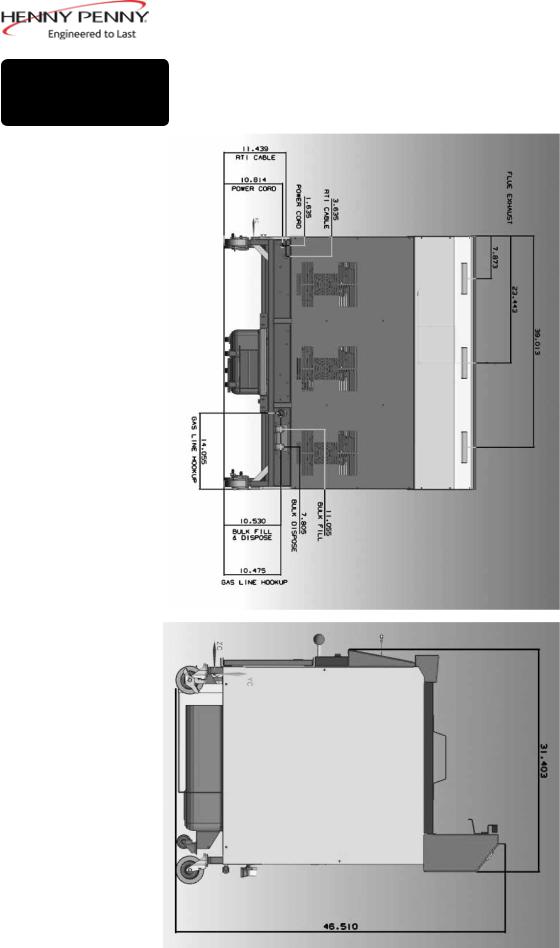
2-13. |
|
DIMENSIONS |
3-WELL |
|
Back
Side
Side dimensions are the same for both 153
& 154 units.
Aug. 2013 |
12 |
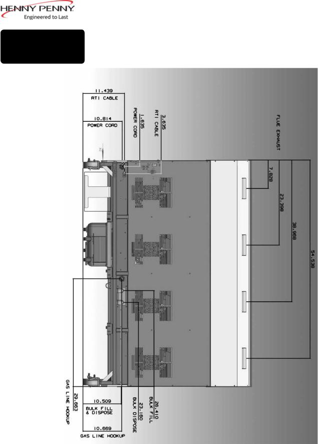
2-13.
DIMENSIONS 4 WELL (CONT.)
Back
Aug. 2013 |
13 |
SECTION 3: OPERATION
3-1. |
Refer to explanations on the next pages. |
OPERATING |
|
COMPONENTS |
|
Figure 3-1
1
2
4 |
3 |
2 |
5 |
6 |
7 |
|
|
|
|
|
1 |
|
|
|
|
|
3 |
8 |
9 |
10 |
8 |
|||
|
|
|
|
13 |
||
11 |
|
|
12 |
|
||
|
|
|
|
|
|
|
|
|
|
|
|
|
|
|
|
|
|
|
|
|
Figure 3-2 |
Figure 3-3 |
|
Figure 3-4
Aug. 2013 |
15 |
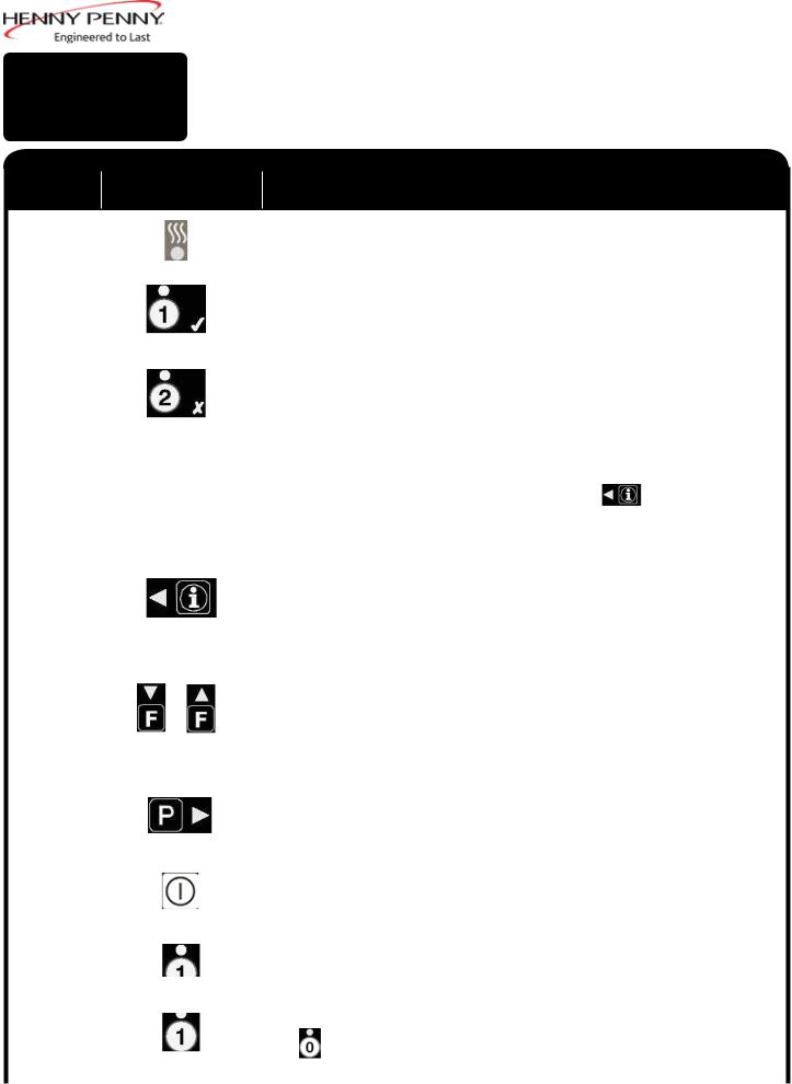
3-1. OPERATING COMPONENTS (CONT.)
Fig. |
Item |
Description |
Function |
|
No. |
||||
|
|
|
|
|
|
This LED lights when the control calls for heat for the left/ right vat, and the |
||
3-1 |
1 |
|
burners ignite and heat the oil |
|
|
|
|
|
|
||
|
|
|
During normal operation, press this button to start and stop cook cycles for the |
||
3-1 |
2 |
|
left basket; press to change displayed product; also used for √ to indicate YES |
||
|
or to confirm |
|
|||
|
|
|
|
||
|
|
|
|
||
|
|
|
During normal operation, press this button to start and stop cook cycles for the |
||
3-1 |
3 |
|
left basket; press to change displayed product; also used for X to indicate NO |
||
|
or cancel |
|
|||
|
|
|
|
||
|
|
|
|
||
|
|
|
Shows the product codes; shows the timer countdown during cook cycles; |
||
|
|
Digital Display |
shows the prompts during the filter modes; shows the selections in the Program |
||
3-1 |
4 |
Mode; shows the temperature of the oil by pressing |
; shows error codes |
||
|
|
|
(also displays in several languages) |
|
|
|
|
|
|
||
|
|
|
Press once to view actual oil temperature; press twice to view oil set-point |
||
|
|
|
temperature; and press three times to view recovery information for each vat |
||
3-1 |
5 |
|
from 250oF-300oF (121oC-149oC). Used in Programming Modes; used as ◄ |
||
|
|
|
button to back-up to a previous parameter in Program and Filter Modes. |
||
|
|
|
|
||
|
|
|
Used to access the Filter Menu; also used for ▲ or ▼ buttons; press once to |
||
|
|
|
view the number of cook cycles before next filter in Global Filter or the mode |
||
3-1 |
6 |
|
or percentage of filter allowance in Mixed Filter; press twice to view the time |
||
|
and date of the most recent filter on each vat; press three times to view the |
||||
|
|
|
|||
|
|
|
number of hours of use of the filter pad presently in the drain pan. |
||
|
|
|
|
||
|
|
|
Used to access the Program Modes; used as ► button to advance to the next |
||
3-1 |
7 |
|
parameters in Program and Filter Modes; press to select 2nd languages and |
||
|
volumes |
|
|
||
|
|
|
|
|
|
|
|
|
|
||
|
|
|
Press to turn on and off the heat system for the left vat(s); on full vats either |
||
3-1 |
8 |
|
button can be used |
|
|
|
|
|
|
||
|
|
|
Each product button LED lights when that particular product has been |
||
3-1 |
9 |
|
selected, or when it is compatible with cook temperature. |
|
|
|
|
|
|
||
|
|
|
Press to select the desired product; press to place the letters under the button, |
||
3-1 |
10 |
|
during naming a product in Program Mode |
|
|
|
The |
can be used to start an Idle Mode if enabled in Special Program Mode |
|||
|
|
|
|||
|
|
|
|
|
|
Aug. 2013 |
16 |

3-1. OPERATING COMPONENTS (CONT.)
Fig. |
Item |
Description |
Function |
|
No. |
||||
|
|
|
|
|
|
AFilter Beacon® is found beside each black drain knob; when lit blue, indicates |
3-2 |
11 |
|
the oil should be filtered at this time; beacon flashes when the drain needs |
|
opened or closed |
||
|
|
|
|
|
|
|
|
|
|
|
When the power switch is turned to the ON position, power is supplied to the |
3-3 |
12 |
|
controls and pumps |
|
|
|
|
|
|
|
For fryers with a bulk oil supply, press this button to fill the BIB |
3-4 |
13 |
|
|
|
|
|
|
Aug. 2013 |
17 |
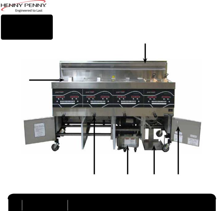
3-1. OPERATING COMPONENTS
(CONT.)
3
4
2 |
1 |
5 |
6 |
Item |
Description |
Function |
|
No. |
|||
|
|
||
1 |
Filter Drain Pan Assy. |
Oil is drained into this pan and then is pumped through filters to help |
|
|
|
prolong the use of the oil |
|
2 |
Drain Valve Knob |
Pull-out on black knobs to open drain valve and oil drains from vat; Push- |
|
|
in to close drain valve and oil can be pumped into vat |
||
|
|
||
3 |
Basket Rest |
The baskets hang on this when not in use, or to drain the product after a |
|
|
cook cycle |
||
|
|
||
4 |
Vat Covers |
Covers the vat when not in use |
|
5 |
BIB Support |
Area that holds the Jug-in-a-Box; holds oil to be pumped into vats to top- |
|
|
off the oil level by the Oil Guardian™ process |
||
|
|
||
6 |
Quick Reference |
Holds operational cards |
|
|
Cards Hook |
|
March 2014 |
18 |
 Loading...