


Computron 8000
Table of contents
 Loading...

Model 8000 Computron
LIMITED WARRANTY FOR HENNY PENNY APPLIANCES
Subject to the following conditions, Henny Penny Corporation makes the following limited warranties to the
original purchaser only for Henny Penny appliances and replacement parts:
NEW EQUIPMENT: Any part of a new appliance, except lamps and fuses, which proves to be
defective in material or workmanship within two (2) years from date of original installation, will be
repaired or replaced without charge F.O.B. factory, Eaton, Ohio, or F.O.B. authorized distributor. To
validate this warranty, the registration card for the appliance must be mailed to Henny Penny within ten
(10) days after installation.
REPLACEMENT PARTS: Any appliance replacement part, except lamps and fuses, which proves to
be defective in material or workmanship within ninety (90) days from date of original installation will be
repaired or replaced without charge F.O.B. factory, Eaton, Ohio, or F.O.B. authorized distributor.
The warranty for new equipment and replacement parts covers only the repair or replacement of the defective
part and does not include any labor charges for the removal and installation of any parts, travel or other expenses
incidental to the repair or replacement of a part.
EXTENDED FRYPOT WARRANTY: Henny Penny will replace any frypot that fails due to manufacturing or
workmanship issues for a period of up to seven (7) years from date of manufacture. This warranty shall not cover
any frypot that fails due to any misuse or abuse, such as heating of the frypot without shortening.
0 TO 3 YEARS: During this time, any frypot that fails due to manufacturing or workmanship
issues will be replaced at no charge for parts, labor, or freight. Henny Penny will either install a
new frypot at no cost or provide a new or reconditioned replacement fryer at no cost.
3 TO 7 YEARS: During this time, any frypot that fails due to manufacturing or workmanship
issues will be replaced at no charge for the frypot only. Any freight charges and labor costs to
install the new frypot as well as the cost of any other parts replaced, such as insulation,
temperature probes, high limits, fittings, and hardware, will be the responsibility of the owner.
Any claim must be presented to either Henny Penny or the distributor from whom the appliance was
purchased. No allowance will be granted for repairs made by anyone else without Henny Penny’s
written consent. If damage occurs during shipping, notify the sender at once so that a claim may be
filed.
THE ABOVE LIMITED WARRANTY SETS FORTH THE SOLE REMEDY AGAINST HENNY PENNY
FOR ANY BREACH OF WARRANTY OR OTHER TERM. BUYER AGREES THAT NO OTHER REMEDY
(INCLUDING CLAIMS FOR ANY INCIDENTAL OR CONSQUENTIAL DAMAGES) SHALL BE
AVAILABLE.
The above limited warranty does not apply (a) to damage resulting from accident, alteration, misuse, or abuse;
(b) if the equipment’s serial number is removed or defaced; or (c) for lamps and fuses. THE ABOVE LIMITED
WARRANTY IS EXPRESSLY IN LIEU OF ALL OTHER WARRANTIES, EXPRESS OR IMPLIED,
INCLUDING MERCHANTABILITY AND FITNESS, AND ALL OTHER WARRANTIES ARE EXCLUDED.
HENNY PENNY NEITHER ASSUMES NOR AUTHORIZES ANY PERSON TO ASSUME FOR IT ANY
OTHER OBLIGATION OR LIABILITY.
FM01-909

Model 8000 Computron
TABLE OF CONTENTS
Section Page
Section 1. OPERATION ................................................................................................................... 1-1
1-1. Introduction ............................................................................................................ 1-1
1-2. Operating Controls ................................................................................................. 1-1
1-3. Clock Set ................................................................................................................ 1-4
1-4. Basic Operations and Procedures ........................................................................... 1-6
1-5. Clean-Out Mode..................................................................................................... 1-9
Section 2. PROGRAMMING .......................................................................................................... 2-1
2-1. Introduction ............................................................................................................ 2-1
2-2. Product Program Mode ..........................................................................................2-1
2-3. Special Program Mode........................................................................................... 2-8
2-4. Data Logging, Heat Control, Tech Mode, and Stat Mode...................................... 2-16
2-5. Program Settings Worksheets ................................................................................2-16
Section 3 ERROR CODES
3-1. Introduction ............................................................................................................ 3-1
3-2. Error Codes Table ..................................................................................................3-1
Section 4 INFORMATION MODE
4-1. Information Mode Functions.................................................................................. 4-1
Section 5 PARTS INFORMATION & WIRING DIAGRAMS
5-1. Introduction ............................................................................................................ 5-1
5-2. Genuine Parts .........................................................................................................5-1
5-3. How to Order.......................................................................................................... 5-1
5-4. Prices......................................................................................................................5-1
5-5. Delivery.................................................................................................................. 5-1
5-6. Warranty................................................................................................................. 5-1
Wiring Diagrams.................................................................................................... 5-4
Distributor Lists - Domestic and International
ii 902

Model 8000 Computron
1-1. INTRODUCTION This section provides basic operating procedures for the
Henny Penny Computron 8000 fryer. See fryer Operator
Manual for more details on fryer operation.
1-2. SAFETY The only way to insure safe operation of the Henny Penny
Computron 8000 fryer is to fully understand the proper
installation, operation and maintenance procedures, found in
the fryer Operator’s Manual. The instructions in this manual
have been prepared to aid you in learning the controls.
Where information is of particular importance or is safety
related, the words NOTICE, CAUTION, or WARNING are
used. Their usage is described below:
SAFETY ALERT SYMBOL is used with DANGER,
WARNING, or CAUTION which indicates a personal
injury type hazard.
NOTICE is used to highlight especially important
information.
CAUTION used without the safety alert symbol
indicates a potentially hazardous situation
which, if not avoided, may result in property damage.
CAUTION indicates a potentially hazardous
situation which, if not avoided, may result in
minor or moderate injury.
WARNING indicates a potentially hazardous
situation which, if not avoided, could result in
death or serious injury.
DANGER INDICATES AN IMMINENTLY
HAZARDOUS SITUATION WHICH, IF NOT
AVOIDED, WILL RESULT IN DEATH OR
SERIOUS INJURY.
103 1-1
SECTION 1. OPERATION
Model 8000 Computron
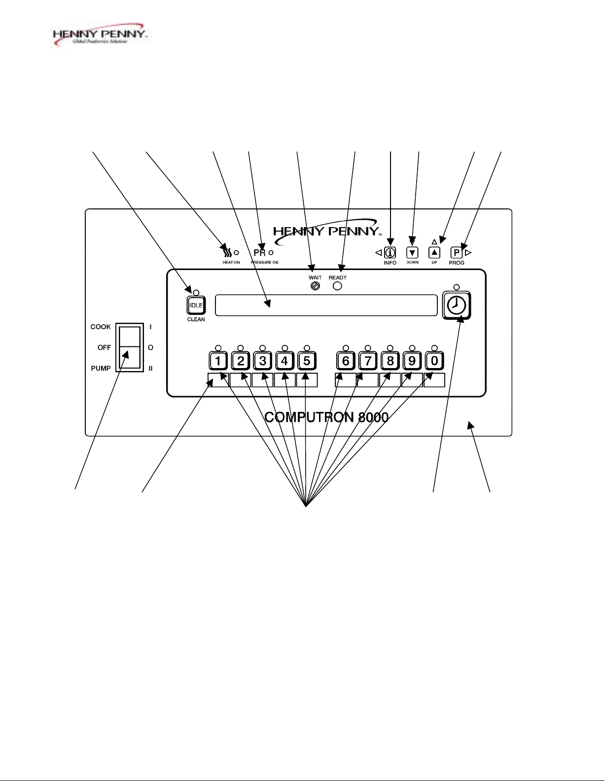
1-3. OPERATING CONTROLS Refer to Figure 1-1.
Fig. Item Description Function
No. No.
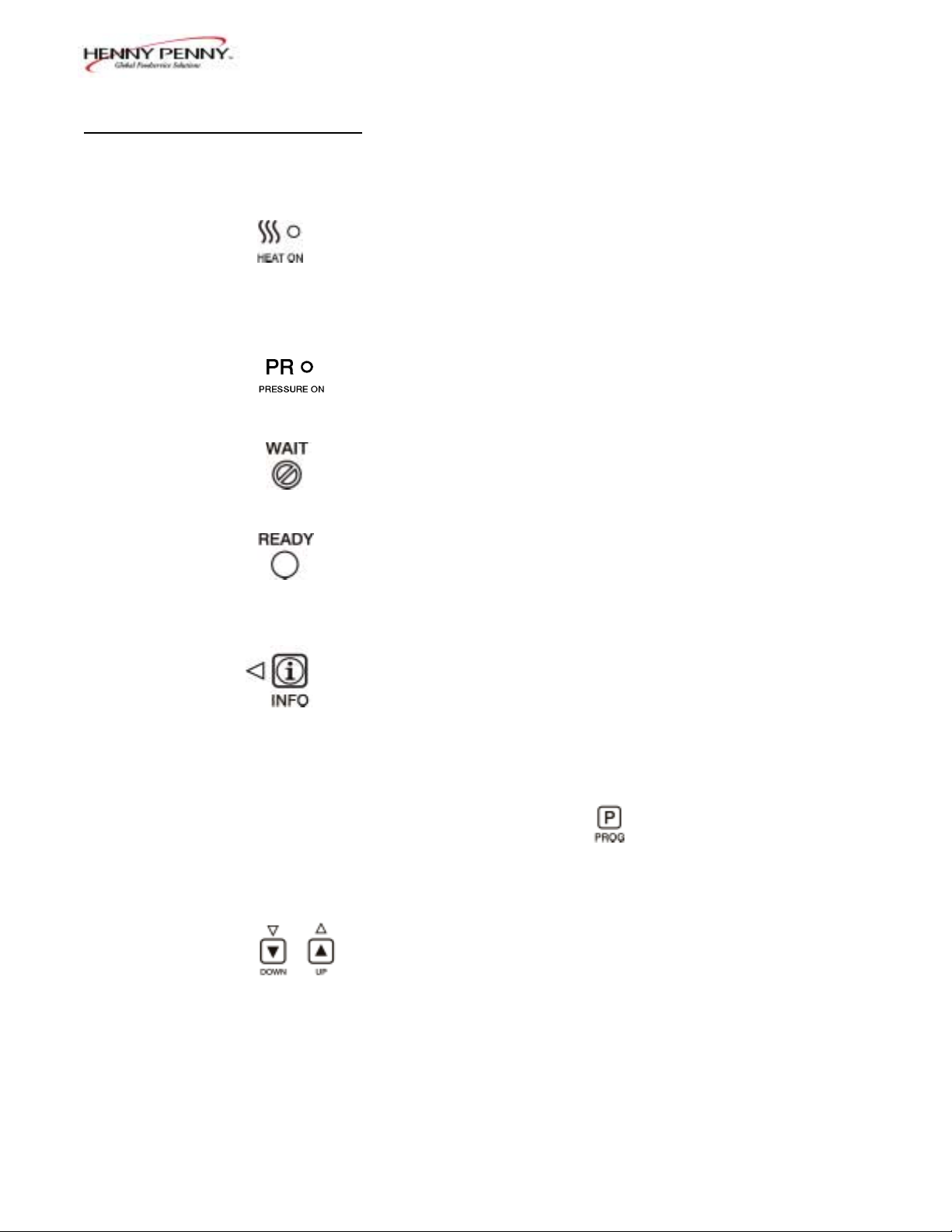
1-1 1 Lights when the control calls for heat. The elements or
burners come on and heat the shortening.
1-1 2 Digital Display Shows all the functions of the cook cycle, program modes,
diagnostic modes, and alarms.
1-1 3 Lights when the solenoid closes and pressure starts to build
inside frypot.
1-1 4 Flashes when the shortening temperature is NOT at the
proper temperature for cooking product.
1-1 5 Lights when the shortening temperature is 5° F below to
15° F above the cooking temperature, signaling the operator
that the shortening temperature IS at the proper temperature
for cooking product.
1-1 6 Press to display the following fryer information and status:
a. The temperature of the shortening
b. The temperature setpoint
c. The number of cook cycles until Filter Lockout
d. Date and Time
If pressed in the Program Mode, shows previous settings.
Pressing this along with accesses the Information
Mode which has historic information on the operator and
fryer’s performance.
1-1 7 & 8 Used to adjust the value of the currently displayed setting in
the Program modes.
1-2 103
Model 8000 Computron
1-3. OPERATING CONTROLS
(Continued)
Fig. Item Description Function
No. No.
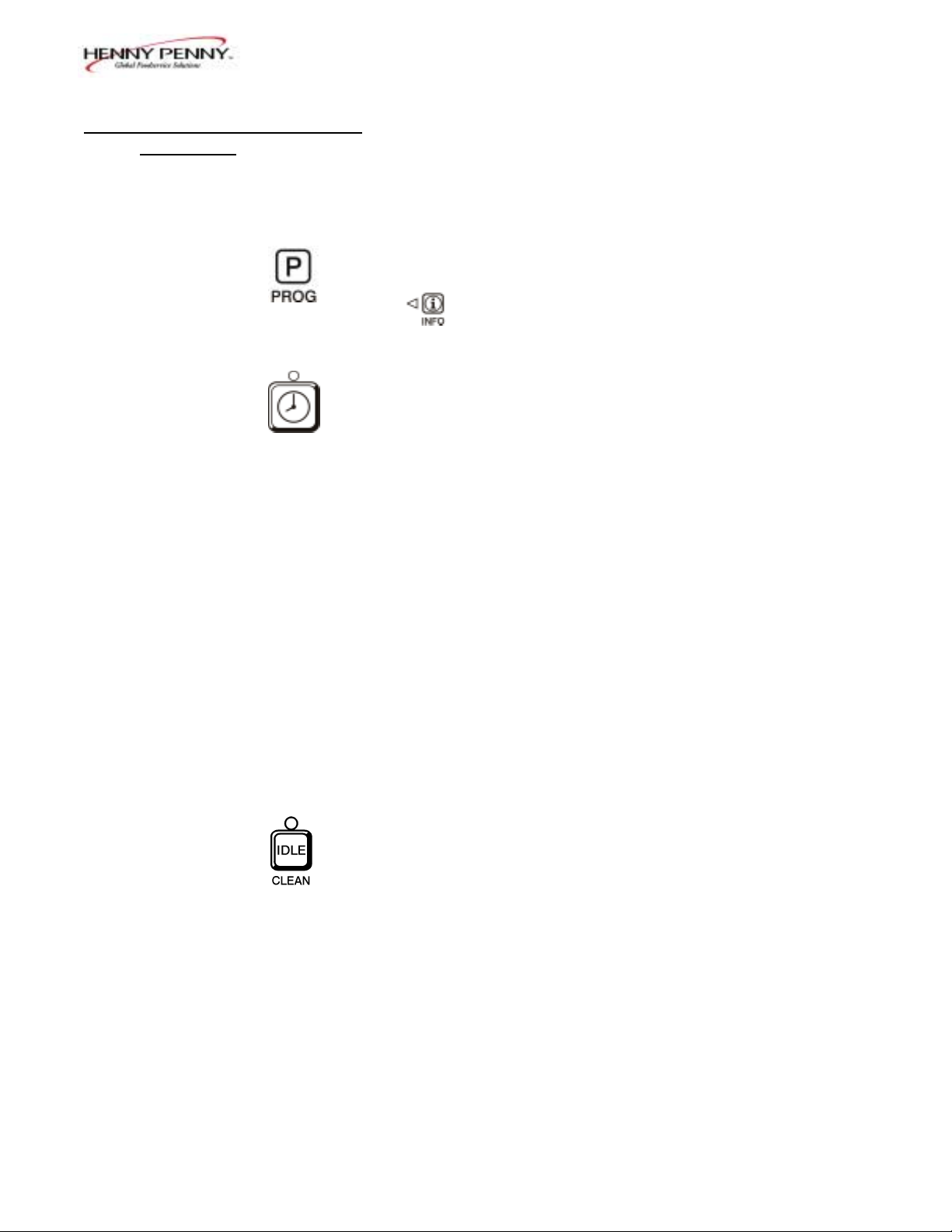
1-1 9 Press to access program modes. Once in the program mode, it
is used to advance to the next setting. If pressed along with
it accesses the Information Mode which has historic
information on the operator and fryer’s performance.
1-1 10 Used to start and stop cook cycles, and to stop the timer at
the end of a holding cycle.
1-1 11 Menu Card The name of the food product associated with each Product
Window Selection button. The menu card strip is located behind the
decal.
1-1 12 Product Select Are used to select the product for cooking.
Buttons To use them to start cook cycles, see section 3, Special
Program Mode item SP-10.
1-1 13 Cook/Pump Switch A 3-way switch with a center OFF position. Turn the switch
to the Cook position to operate the fryer. Turn the switch to
the Pump position to operate the filter pump. Certain
conditions must be met before operating the filter pump.
These conditions are covered later in the Filtering Section of
the fryer manual.
1-1 14 Used to manually enter an Idle Mode, or Clean-out Mode.
103 1-3
Model 8000 Computron
14 1 2 3 4 5 6 7 8 9
13 11 10 15
12
Figure. 1-1
1-4 103
Model 8000 Computron
1-4. CLOCK SET
Upon initial start-up, or PC board replacement, if
“CLOCK SET” automatically appears in the display,
start with step 4.
1. Press and hold for 5 seconds until “LEVEL 2”
shows in display.
2. Press and “CLOCK SET”, “ENTER CODE”
shows in display.
3. Press . .
4. “CS-1, SET, MONTH”, and the month flashes in the
display.
5. Press the to change the month.
6. Press and “CS-2, SET, DATE” shows in the
display, with the date flashing.
7. Press to change the date.
8. Press and “CS-3, SET, YEAR” shows in the
display, along with the year flashing.
9. Press to change the year.
10. Press and “CS-4, SET, HOUR” shows in the
display, with the hour and “AM” or “PM” flashing.
11. Press to change the hour and AM/PM setting.
12. Press and “CS-5, SET, MINUTE” shows in the
display, with the minutes flashing.
13. Press to change the minutes.
103 1-5
Model 8000 Computron
1-4. CLOCK SET 14. Press and “CS-6, CLOCK MODE” shows in the
(Continued)
display, along with “1.AM/PM”.
“1.AM/PM” is 12 hour time, “2.24-HR” is 24 hour
time. Press to change.
15. Press and “CS-7, DAYLIGHT SAVINGS ADJ”
shows in the display, along with “2.US”.
Press to change to the following:
a. “1.OFF” = No automatic adjustments for Daylight
Savings Time.
b. “2.US” = Automatically applies United States
Daylight Savings Time adjustment. DST activated
on the first Sunday in April. DST de-activated on
the last Sunday in October.
c. “3.EURO” = Automatically applies European (CE)
Daylight Saving Time adjustment. DST activated
on the last Sunday in March. DST de-activated on
the last Sunday in October.
16. Press and “CS-8, BEGIN NEW DAY” shows in
display, along with “3:00AM”.
This setting indicates the time of day that statistics start
accumulating for a new day. If set to 3:00AM, for
example, then late night cook cycles and filter
operations from midnight to 3:00AM Tuesday morning,
are accumulated with Monday's statistics.
The CS-8 value can be set from 12:00AM (midnight) to
8:00AM, in half hour increments (12:00 AM,
12:30 AM, 1:00 AM, 1:30 AM, etc.). The default value
for general market software is 3:00 AM.
Press to change the time the “new” day starts.
17. Clock Set is now complete. Press and hold to exit.
1-6 103
Model 8000 Computron
1-5. BASIC OPERATIONS These are just basic procedures. Refer to the Operator’s
AND PROCEDURES 500/600/561 manual for more detailed instructions.
1. Be sure the drain valve is in the closed position.
2. Remove fry basket from frypot and leave lid up.
3. Fill the frypot with shortening.
When using new shortening, it is recommended to melt
the shortening on an outside source before placing
shortening in the frypot. Unless elements are
completely covered in shortening, fire or damage to the
frypot could result.
4. Move power switch to the "COOK" position. Unit
automatically goes into the melt cycle. When the
temperature reaches 230°F (110°C) the control goes
into the heat cycle, and heats the shortening until the
temperature setting is reached.
Bypass the melt cycle, if desired, by pressing a Product
button and holding it for five seconds. The display
shows “EXIT MELT? 1=YES 2=NO”. Press
to exit melt.
Do not bypass the melt cycle unless enough shortening
has melted to completely cover all of the heating
elements, or the curved surface of the gas frypot. If melt
cycle is bypassed before these surfaces are covered,
excessive smoking of the shortening or a fire will result.
5. Once out of the Melt cycle, flashes until
5° before setpoint temperature is reached. Then
illuminates and the selected product shows
in the display.
103 1-7
Model 8000 Computron
1-5. BASIC OPERATIONS 6. Completely stir shortening to stabilize the temperature
AND PROCEDURES throughout the frypot.
(Continued)
7. Once the shortening temperature has stabilized at the
setpoint temperature, place the baskets into the
shortening. Then place product into the basket.
Do not overload, or place product with extreme
moisture content into the basket. 18 lbs. (8.2 kgs.)
for the 561 and 12 lbs. (5.4 kgs.) for the 500 and 600,
is the maximum amount of product per frypot.
Failure to follow these directions can result in
shortening overflowing the frypot. Serious burns or
damage to the frypot could result.
8. Lift the basket slightly out of the shortening and shake
basket to separate pieces.
9. Remove basket handle and close lid quickly, latching
the lid.
10. Tighten the lid spindle clockwise, sealing the lid. Align
red knob on the spindle with red knob on the latch.
LATCH THE LID PROPERLY AND ALIGN THE
RED BALLS OR SEVERE BURNS WILL
RESULT.
11. Press to start a cook cycle.
The display counts down the cooking time.
A different product can be selected during the first
minute of cooking, in case the wrong Product Button
was pressed. To check the shortening temperature
press or to stop a cook cycle, press .
1-8 103

Model 8000 Computron
1-5. BASIC OPERATIONS 12. Within a few minutes, the pressure gauge increases to
AND PROCEDURES the OPERATING ZONE. If not, recheck the install-
(Continued) ation and operation procedures in Operator’s Manual.
13. Near the end of the cook cycle the fryer automatically
depressurizes, an alarm sounds and the display flashes
“DONE”. To stop the alarm, press .
DO NOT ATTEMPT TO OPEN LID UNTIL THE
PRESSURE DROPS TO ZERO. LID IS LOCKED
WHEN FRYER IS UNDER PRESSURE. DO NOT
ATTEMPT TO FORCE THE LID LATCH OR
OPEN THE LID WHILE UNDER PRESSURE.
OPENING THE LID WHEN THE FRYPOT IS
PRESSURIZED ALLOWS HOT SHORTENING
AND STEAM TO ESCAPE FROM THE FRYPOT,
RESULTING IN SEVERE BURNS.
14. After pressure drops to zero, turn the spindle counter-
clockwise.
Do not flip or spin the spindle cross arm when opening
the lid because it could damage the acme nut inside the
cross bar.
15. Unlatch and raise the lid quickly to allow most of the
condensation on the lid to drain through the drain
channel and not into the shortening.
Do not let the lid slam up against the backstop
because damage to the hinge could result.
16. Using the detachable handle, lift the basket and inspect
product for doneness. Dump product into holding pan.
17. If a Quality time (hold time) was programmed, the
controller automatically starts the hold timer. The
display alternately shows the product selected and the
quality time remaining in minutes. If a different
product is selected during the hold cycle, the display
only shows the product selected.
103 1-9

Model 8000 Computron
1-5. BASIC OPERATIONS 18. At the end of the Hold mode, a tone sounds, the
AND PROCEDURES display flashes “QUALITY”, and the product it was
(Continued) timing. Press and release .
In the Cook mode, when "FILTER SUGGESTED”,
shows in the display, the operator has the option to
filter at this time, or to continue cooking. But, if the
operator continues cooking, a Filter Lockout occurs
within the next cook cycle, or two.
When "FILTER LOCKOUT" , then "YOU *MUST*
FILTER NOW........” shows in the display, is the only
button that functions, until the unit is filtered. Follow the
steps in the 500/600/561 Service manual on filtering.
1-6. CLEAN-OUT MODE The Computron 8000 has a Clean-Out Mode to clean the
frypot upon initial start-up and every change of shortening.
Follow the steps in the 500/600/561 Service manual on
Cleaning the Frypot.
When heating the cleaning solution and vinegar solutions,
turn the Cook/Pump switch to “COOK. ” When the fryer
starts the Melt Cycle, press and hold then
“CLEAN-OUT ?”, “1=YES 2=NO”shows in display. Press
to start Clean-Out mode. The fryer displays
“*CLEAN-OUT MODE*” and heats up to a preprogrammed
temperature, then automatically begins a preset timed
countdown. Use the UP and DOWN buttons, if necessary, to
adjust the temperature and keep the cleaning solution from
boiling over.
See Special Program Modes SP-10 and SP-11
to preset the temperature and time.
1-10 103

Model 8000 Computron
1-6. CLEAN-OUT MODE
Continued)
NEVER PRESSURIZE FRYER TO CLEAN. LEAVE
THE LID OPEN. WATER UNDER PRESSURE IS
SUPER HEATED AND CAUSES SEVERE BURNS IF
IT COMES IN CONTACT WITH SKIN.
If the cleaning solution in the frypot starts to foam
and boil over, immediately turn the Cook/Pump
Switch to OFF and do not try to contain it by closing
the fryer lid or severe burns could result.
103 1-11

Model 8000 Computron
2-1. INTRODUCTION The controls are preset from the factory, but desired functions
can be programmed in the field. This section includes the
Product Programming Mode, which are the basic settings,
and the Level 2 programming, which are the more detailed
settings.
2-2. PRODUCT PROGRAM This mode allows the operator to change and set various
MODE parameters for each product.
1. Press and hold for one second until
“PROG” shows in the display, followed by
“ENTER CODE”.
2. Enter code 1, 2, 3. "SELECT PRODUCT…PRESS
PROG” scrolls across the display.
3. Press and release the desired Product button (1 to 10).
Press to copy a product, erase a product, preset a
product, erase all products, or preset all products.
4. Press and release . The name of that product
shows in the display. Ex. “ NAME“FRIES”.
Change Product Names
a. Press and release and the first letter, or digit,
starts flashing.
b. Press and release to change the flashing letter.
c. To continue to the next letter, press . Then press
to change this letter.
d. Repeat step c until up to 7 letters are entered.
103 2-1
SECTION 2. PROGRAMMING
Loading...