

Page 1
User‘s Manual
PROFIBUS-DP
Interface for Encoders
English (en)
12/2012
Page 2

Contents
Contents
List of tables .......................................................................................................................... 5
List of figures ......................................................................................................................... 7
1 General information ....................................................................................................... 8
1. 1 Encoder gateway .................................................................................................... 8
1. 2 Absolute encoders ................................................................................................. 8
1. 3 PROFIBUS technology ........................................................................................... 9
1.3.1 PROFIBUS DP functionality levels ............................................................. 9
1. 4 References ............................................................................................................ 10
1.4.1 Abbreviations ............................................................................................. 10
2 Encoder gateway installation ...................................................................................... 11
2.1 Settings inside the gateway .................................................................................. 11
2.1.1 Node address ............................................................................................ 12
2.1.2 Bus termination ......................................................................................... 13
2.2 Power supply ......................................................................................................... 14
2.3 BUS lines ............................................................................................................... 16
2.4 Shielding philosophy ..............................................................................................18
2.5 GSD file ..................................................................................................................18
2.6 LED indication ........................................................................................................ 19
3 Absolute encoder installation .................................................................................... 20
3.1 Settings inside the encoder ................................................................................. 20
3.1.1 Node address ........................................................................................... 20
3.1.2 Bus termination ........................................................................................ 21
3.2 Connecting the encoder ....................................................................................... 22
3.2.1 Bus lines ................................................................................................... 24
3.3 Shielding philosophy ............................................................................................. 26
3.4 GSD file ................................................................................................................. 26
3.5 LED indication ....................................................................................................... 27
4 Configuration example ................................................................................................ 28
4.1 Device description file installation (GSD-file) ....................................................... 28
4.2 Setting the encoder gateway configuration ......................................................... 29
4.3 Setting encoder gateway parameters .................................................................. 32
4.4 Isochrone mode parameter settings -BUS .......................................................... 34
4.5 Isochrone mode parameter settings DPV2 slave ................................................ 36
2
Page 3

Contents
5 PROFIBUS IO data description ................................................................................... 37
5.1 Encoder profile for PROFIBUS version 4.1 .......................................................... 37
5.2 Application class definition ................................................................................... 38
5.3 Standard signals ................................................................................................... 38
5.4 Standard telegrams .............................................................................................. 39
5.4.1 Standard telegram 81 ............................................................................... 39
5.4.2 Standard telegram 82 ............................................................................... 40
5.4.3 Standard telegram 83 ............................................................................... 41
5.4.4 Standard telegram 84 ............................................................................... 42
5.5 Format of G1_XIST1 and G1_XIST2 ..................................................................... 43
5.6 Format of G1_XIST3 ............................................................................................. 44
5.7 Control word 2 (STW2_ENC) ............................................................................... 45
5.8 Status word 2 (ZSW2_ENC) ................................................................................. 46
5.9 Control word (G1_STW) ....................................................................................... 47
5. 10 Status word (G1_ZSW)......................................................................................... 48
5.11 Isochronous operation .......................................................................................... 49
6 Alarms and warnings ................................................................................................... 51
6.1 Alarm mechanism ................................................................................................ 51
6.2 Channel related diagnosis .................................................................................... 51
6.3 Faults ..................................................................................................................... 52
6.4 Error message ...................................................................................................... 53
7 Acyclic parameter data ................................................................................................ 54
7. 1 Acyclic data exchange .......................................................................................... 54
7. 2 Identification and Maintenance (I&M functions) ................................................. 54
7. 3 Base mode parameter access ............................................................................. 55
7.3.1 General characteristics ............................................................................. 55
7.3.2 Parameter requests and responses ......................................................... 55
7.3.3 Changing the preset value........................................................................ 55
7.3.4 Reading the preset value .......................................................................... 56
7. 4 Detailed description of supported parameters .................................................... 57
7.4.1 Parameter 918, read only ......................................................................... 57
7.4.2 Parameter 922, read only ......................................................................... 57
7.4.3 Parameter 925, read/write ........................................................................ 57
7.4.4 Parameter 964, read only ......................................................................... 57
7.4.5 Parameter 965, read only ......................................................................... 57
7.4.6 Parameter 971, read/write ........................................................................ 57
7.4.7 Parameter 974, read only .......................................................................... 57
7.4.8 Parameter 975, read only ......................................................................... 58
7.4.9 Parameter 979, read only ......................................................................... 58
7.4.10 Parameter 980, read only ......................................................................... 59
7.4.11 Parameter 65000 read/write .................................................................... 59
7.4.12 Parameter 65001, read only ..................................................................... 59
7.4.13 Parameter 65002, read/write ................................................................... 60
7.4.14 Parameter 65003, read only ..................................................................... 60
7. 5 Example of reading and writing to a parameter .................................................. 60
7.5.1 Used blocks .............................................................................................. 61
3
Page 4

Contents
8 Functionality in the PROFIBUS DPV2 device ........................................................... 66
8.1 Code sequence .................................................................................................... 67
8.2 Class 4 functionality ............................................................................................. 67
8.3 G1_XIST1 Preset control ...................................................................................... 68
8.4 Scaling function control ........................................................................................ 68
8.5 Alarm channel control ........................................................................................... 69
8.6 Compatibility mode .............................................................................................. 70
8.7 Preset value .......................................................................................................... 71
8.8 Scaling function parameters ................................................................................ 73
8.8.1 Measuring units per revolution ................................................................ 73
8.8.2 Total measuring range ............................................................................... 74
8.9 Maximum master sign-of-life failures .................................................................. 78
8. 10 Velocity measuring units ...................................................................................... 79
8.11 Encoder profile version ......................................................................................... 80
8.12 Operating time...................................................................................................... 81
8.13 Offset value .......................................................................................................... 81
8.14 Acyclic data ........................................................................................................... 82
8.14.1 PROFIdrive parameters ............................................................................ 82
8.14.2 Encoder parameter numbers ................................................................... 83
8.14.3 Parameters 6500 and 65002 -Preset value ............................................. 84
8.14.4 Parameter 65001 operating status parameter structure ......................... 85
8.14.5 Encoder specific parameter 65003- Operating status 64 bit structure ... 87
8.14.6 I&M functions ........................................................................................... 88
9 Encoder state machine ................................................................................................ 89
9.1 Normal operation state......................................................................................... 90
9.1.1 Profile version 4.x ..................................................................................... 90
9.1.2 Profile version 3.x ..................................................................................... 90
9.1.3 Profile version 3.x and 4.x ........................................................................ 90
9.2 Parking state ......................................................................................................... 90
9.3 Set/shift home position (Preset) ........................................................................... 90
9.3.1 Preset depending on different telegrams ................................................ 90
9.3.2 Absolute preset with negative value ........................................................ 91
9.4 Error state ............................................................................................................. 91
9.5 Error acknowledgement ....................................................................................... 91
9.6 Start up ................................................................................................................. 91
10 Revision history ............................................................................................................ 92
4
Page 5

List of tables
List of tables
Table 1 Termination switch settings ........................................................................ 13
Table 2 Pinning M12 power supply connector ....................................................... 14
Table 3 Pinning M12 bus in/out connectors ........................................................... 16
Table 4 Available GSD file for DPV2 gateway ......................................................... 18
Table 5 LED indication ............................................................................................. 19
Table 6 Terminating switch settings ........................................................................ 21
Table 7 Pinning M12 power supply ......................................................................... 22
Table 8 Pinning M12 bus in/out lines ...................................................................... 24
Table 9 Available GSD file for DPV2 encoder ......................................................... 26
Table 10 LED indication encoder .............................................................................. 27
Table 11 Standard signals .......................................................................................... 38
Table 12 Supported telegrams .................................................................................. 39
Table 13 Format of G1_XIST3 ................................................................................... 44
Table 14 STW2_ENC definition ................................................................................. 45
Tabl e 15 Detailed assignment of control word2 (STW2_ENC) ................................ 45
Table 16 ZSW2_ENC definition ................................................................................. 46
Table 17 Detailed assignment of Status word 2 (ZSW2_ENC) ................................ 46
Table 18 G1_STW implementation requirements .................................................... 47
Table 19 G1_ZSW implementation requirements .................................................... 48
Table 20 Channel related diagnostics ....................................................................... 51
Table 21 Faults ........................................................................................................... 52
Table 22 Sensor status word..................................................................................... 53
Table 23 Write of preset value .................................................................................. 55
Table 24 Read of preset value, parameter request .................................................. 56
Table 25 Read of preset value, parameter response ............................................... 56
Table 26 Used hardware components ...................................................................... 60
Table 27 Used software components ....................................................................... 60
Table 28 Parameters of SFB52 ................................................................................. 64
Table 29 Parameters of SFB53 ................................................................................. 64
Table 30 Supported functions ................................................................................... 66
Tabl e 31 Code sequence attributes .......................................................................... 67
Table 32 Class 4 functionality attributes ................................................................... 67
Table 33 G1_XIST1 Preset control attributes ............................................................ 68
Table 34 Scaling function control attributes .............................................................. 68
Table 35 Alarm channel control attributes ................................................................. 69
Table 36 Compatibility mode attributes .................................................................... 70
Table 37 Compatibility mode definition .................................................................... 70
Table 38 Preset value parameters ............................................................................. 72
Table 39 Single turn scaling parameters ................................................................... 73
5
Page 6

List of tables
Table 40 Total measuring range ................................................................................. 74
Table 41 Maximum master sign-of-life parameter ................................................... 78
Table 42 Parameter Velocity measuring unit............................................................. 79
Table 43 Coding of velocity measuring units ............................................................ 79
Table 44 Encoder profile version parameter ............................................................. 80
Table 45 Operating time parameter .......................................................................... 81
Table 46 Offset value parameter ............................................................................... 81
Table 47 Supported PROFIdrive parameters ............................................................ 82
Table 48 Encoder specific parameter ....................................................................... 83
Table 49 Structure of parameter 65000 Preset value .............................................. 84
Table 50 Structure of 65002 Preset value 64 bit ...................................................... 84
Table 51 Structure of 65001 Encoder operating status ............................................ 85
Table 52 Detailed structure of 65001 Operating status ........................................... 85
Table 53 Parameter 65001 Sub index 1: Operating status ....................................... 86
Table 54 Structure of 65003 Operating status 64 bit ............................................... 87
Table 55 Structure of 65003 Operating status 64 bit ............................................... 87
Table 56 Supported I&M functions ........................................................................... 88
Table 57 Revision history .......................................................................................... 92
6
Page 7

List of figures
List of figures
Figure 1 Placement of screws ................................................................................... 11
Figure 2 PCB-view of a cable gland PROFIBUS gateway ........................................ 12
Figure 3 Orientation of M12 power supply connector ............................................. 14
Figure 4 Terminal connections of power supply cables ........................................... 15
Figure 5 Orientation of M12 bus connectors ........................................................... 16
Figure 6 PCB-view of a cable gland encoder ........................................................... 20
Figure 7 Orientation of M12 power supply connector ............................................. 22
Figure 8 Terminal connections of power supply cables ........................................... 23
Figure 9 Orientation of M12 bus connectors ........................................................... 24
Figure 10 Terminal connections of bus line cables .................................................... 25
Figure 11 Overview of encoder profiles ..................................................................... 37
Figure 12 Absolute value in G1_XIST1 ....................................................................... 43
Figure 13 Absolute value in G1_XIST2 ....................................................................... 43
Figure 14 Sequence of the DP-cycle in isochronous mode ....................................... 49
Figure 15 DB1, request data block ............................................................................. 61
Figure 16 DB2, response data block .......................................................................... 61
Figure 17 DB3, instance data block of SFB52 ............................................................ 62
Figure 18 DB4, instance data block of SFB53 ............................................................ 62
Figure 19 OB1, read and write operation ................................................................... 63
Figure 20 Diagnostic address of slot 1 ....................................................................... 65
Figure 21 Variable table ............................................................................................... 65
Figure 22 Cyclic scaling ............................................................................................... 75
Figure 23 Non-cyclic scaling G1_XIST 1 Preset control enabled ............................... 76
Figure 24 Non-cyclic scaling G1_XIST 1 Preset control disabled ............................... 77
7
Page 8

General information
1 General information
This manual describes the installation procedures and
configuration of HEIDENHAIN absolute encoders and encoder
gateways with PROFIBUS DPV2 functionality.
1.1 Encoder gateway
The advantages of the gateway concept is that it allows the use
of small and very robust EnDat encoders, which make the
encoder gateway solution suitable in applications where very high
ambient temperature is a limiting factor. The encoder gateway
supports singleturn encoders with up to 31 bit resolution and
multiturn encoders with up to 37 bits resolution with the
limitations described in this manual.
1.2 Absolute encoders
With an absolute encoder each angular position is assigned a
coded position value generated by a code disc equipped with
several parallel fine graduations tracks which are scanned
individually. On singleturn encoders, i.e. an encoder producing
absolute positions within one revolution, the absolute position
information repeats itself with every revolution. So called multiturn
encoders can also distinguish between revolutions. The numbers
of unique revolutions is determined by the resolution of the
multiturn scanning and repeats itself after the total resolution is
reached.
8
Page 9

1.3 PROFIBUS technology
PROFIBUS is a powerful and versatile 2-wire non-proprietary open
field bus standard defined by several international standards such
as EN 50170, IEC 61158 together with different device profiles.
There are 3 different PROFIBUS versions available today, DP, FMS
and PA. HEIDENHAIN products support the Decentralized
Peripherals (DP) version. In addition to manufacturer-specific
functions, the HEIDENHAIN devices described in this manual
supports application class 3 and 4 according to the encoder profile
3.162 v4.1. The encoder device profile describing encoder
functionality and additional information about PROFIBUS can be
ordered from PROFIBUS User Organization, PNO.
PROFIBUS User Organization
Haid-und-Neu Straβe 7
D 76131 Karlsruhe
Tel: +49 721 96 58 590
Fax: + 49 721 96 58 589
www.profibus.com
Web:
1.3.1 PROFIBUS DP functionality levels
The main functions of the different levels are as follows:
DPV0: Supports the basic functionality for the PROFIBUS
protocol. In principal this means the cyclical I/O communication
and diagnostics. HEIDENHAIN have a separate manual for DPV0
devices.
DPV1: The most important benefits with DPV1 are the expanded
functions for the acyclical data communication and alarm
handling. This is a precondition for parameterization and calibration
of field devices over the bus in runtime.
DPV2: In addition to the functionality above, DPV2 includes
expansions that are required for time critical applications such as
motion control. This means functions such as slave-to-slave
communications and isochronous data exchange (time
synchronization).
General information
9
Page 10

General information
PROFIBUS
Process Field Bus
PI
PROFIBUS and Profinet International
PNO
PROFIBUS Nutzerorganisation e.V.
GSD
German term "Gerätestammdaten". A GSD is the
device database file, also called device datasheet.
DP
Decentral Periphery
Input data
Data which the master receives from the encoder
Output data
Data which the encoder receives from the master.
I&M
Identification and Maintenance
MS1 AR
PROFIBUS MS1 AR (Acyclic data exchange between
master (class1) and slave)
MS2 AR
PROFIBUS MS2 AR (Acyclic data exchange between
master (class2) and slave)
OB
Organization Block
1.4 References
1.4.1 Abbreviations
Profile Encoder V4.1, Order No. 3.162
Profile Drive Technology, PROFIdrive V4.1, Profibus International,
Order Nr: 3.172
PROFIBUS Guidelines, Part 1: Identification & Maintenance
Functions V1.1, Profibus International, Order Nr: 3.502
PROFIBUS Guidelines, Part 3: Diagnosis, Ala rms and Time
Stamping V1.0, Profibus International, Order No. 3.522
PROFIBUS Guidelines: PROFIBUS Interconnection Technology
V1.1, Profibus International, Order No. 2.142
10
Page 11
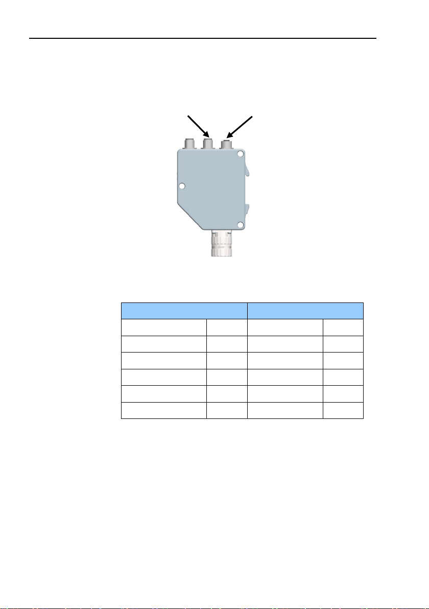
2 Encoder gateway installation
2.1 Settings inside the gateway
The encoder gateway addressing switches and bus termination
must be configured during commissioning of the device. This is
done by removing the back cover, i.e. screwing off the three
screws at the rear of the gateway.
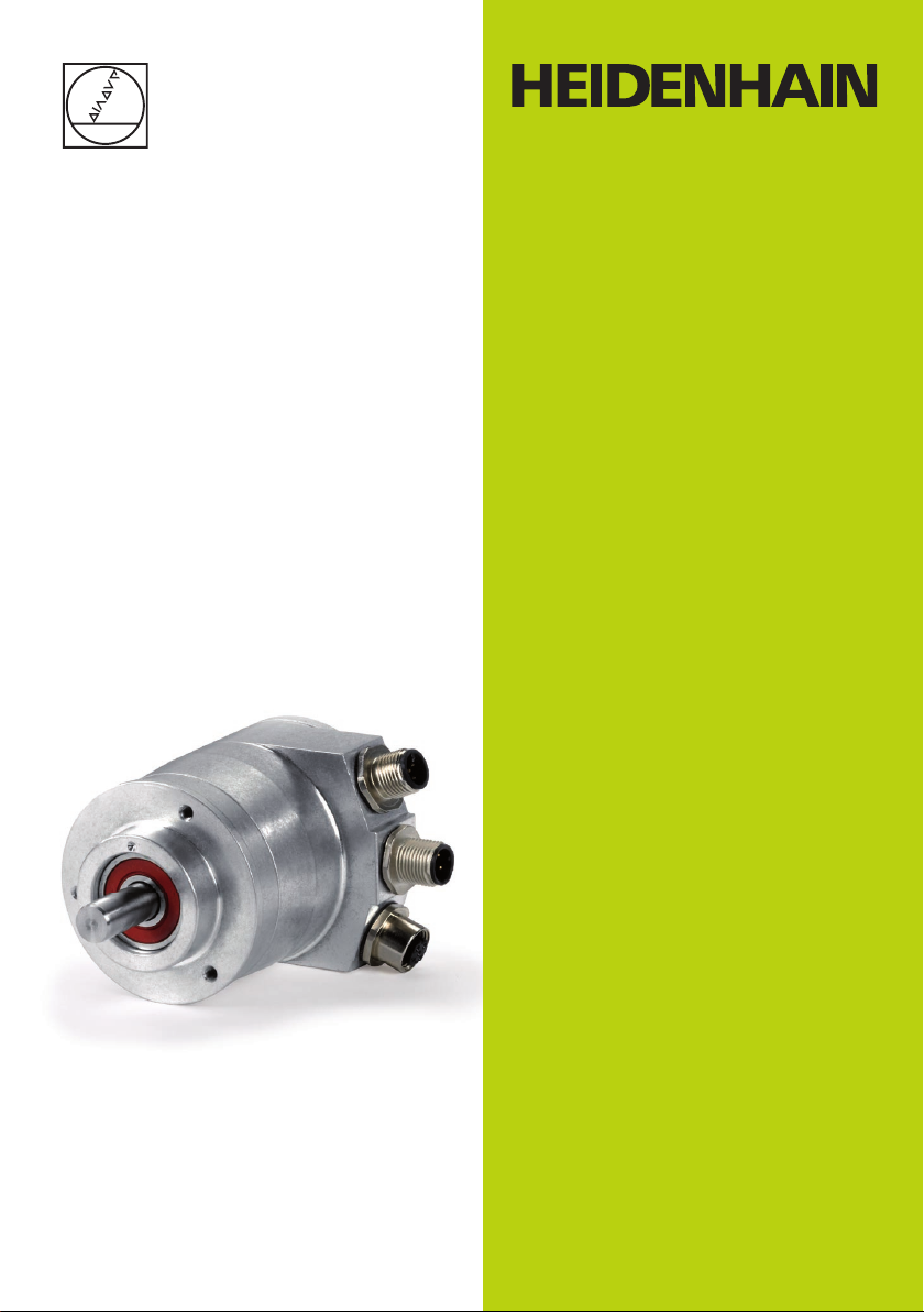
Figure 1 Placement of screws
Encoder gateway installation
Screws to remove
back cover
11
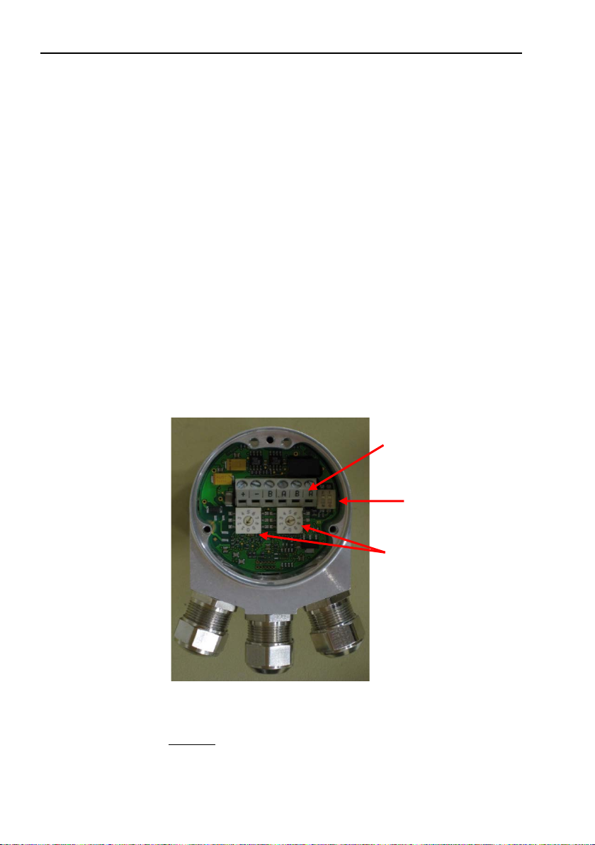
Page 12
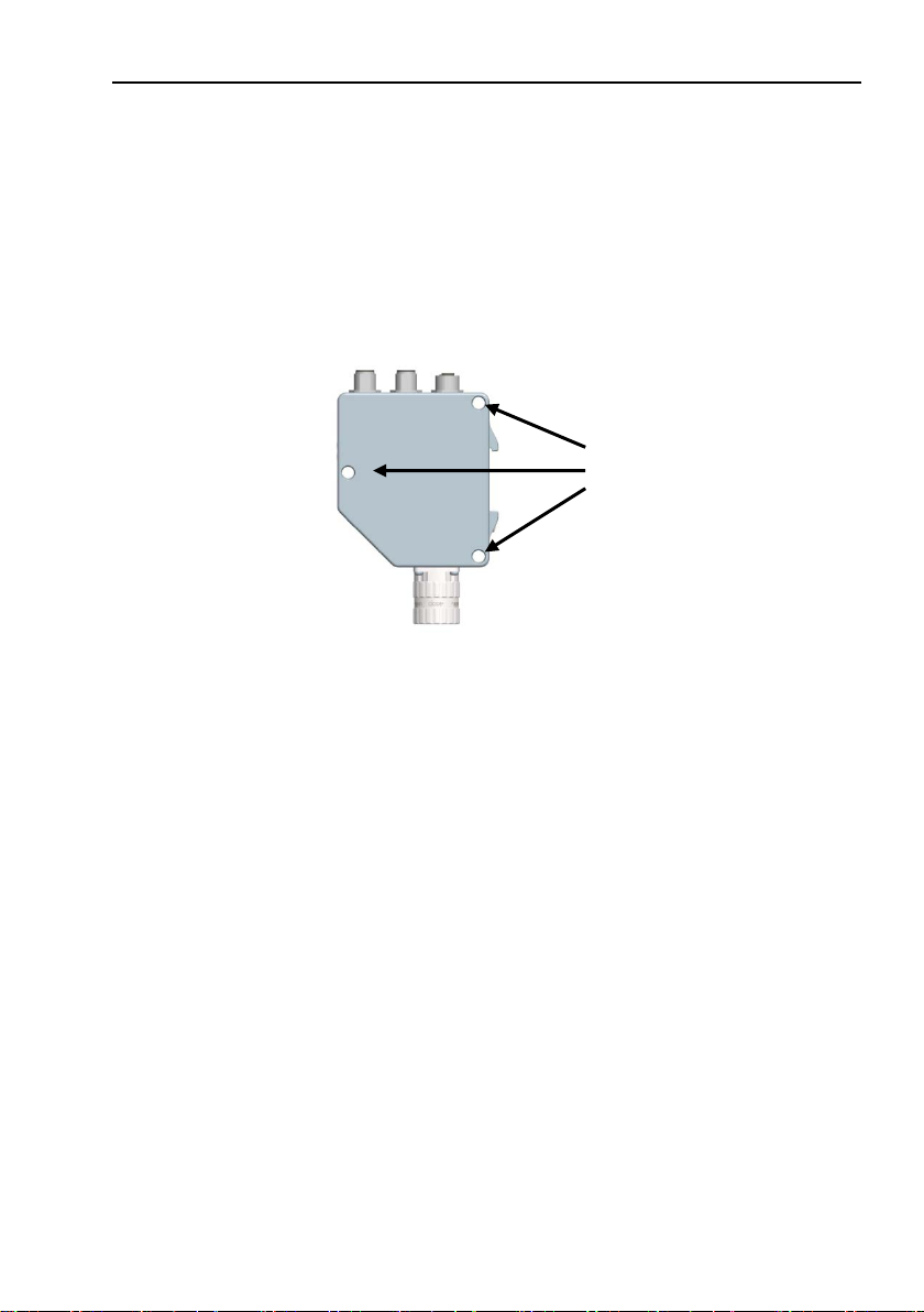
Encoder gateway installation
Screw terminals
Bus termination
switch (on/off)
Node address
switches
2.1.1 Node address
The node address of the encoder gateway can be set via three
decimal rotary switches located inside the back cover. The
weighting, x100, x10 and x1 are specified on the circuit board
besides the switches. Permissible address range is between 0
and 126 but the lower addresses 0 to 2 are usually used by the
master and not recommended to be used by the device. Each
address used in a PROFIBUS network must be unique and may
not be used by other devices.
The device address is only read and adopted when the gateway
power supply is switched on. A restart of the gateway is therefore
required in order to adopt changes done to the address settings.
Figure 2 PCB-view of a cable gland PROFIBUS gateway
Example: To set the node address to 115, the switch to the left
12
(x100) shall be set to 1, the switch in the middle(x10)
should also be set to 1 and the switch to the right(x1)
shall be set to 5.
Page 13

2.1.2 Bus termination
Bit1
Bit2
Effect
On
On
There is a 220ohms resistor between bus A
and bus B line.
On
Off
Not a valid setting
Off
On
Not a valid setting
Off
Off
There is no resistor between bus A and
bus B line.
In a PROFIBUS net, all devices are connected in a bus structure.
Up to 32 devices (master and/or slaves) can be connected in one
segment. When more devices are needed repeaters should be
used to amplify the signals between segments. An active
termination must be added in the beginning and the end of each
bus segment in order to ensure error-free operation. In case of the
gateway with cable glands such terminators are integrated inside
the back cover and can be activated via dip switches as shown in
figure 2. If the device is un-powered the A and B lines are
internally terminated by a 220 Ω resistor.
Table 1 Termination switch settings
When encoder gateways with M12 connectors are used the
termination should be done using a M12 terminating resistor plug.
Note: When M12 terminating resistor plugs are used, the
internal terminating switch shall not be activated.
Encoder gateway installation
13
Page 14
Encoder gateway installation
Power supply M12 version
Function
Pin
+E Volt (9-36V)
1
Not connected
2
0 Volt
3
Not connected
4
Power supply
2.2 Power supply
The power supply connection of M12 equipped gateways are
constituted by a male A-coded 4 pin M12 connector.
Figure 3 Orientation of M12 power supply connector
14
Table 2 Pinning M12 power supply connector
Page 15

Encoder gateways equipped with cable glands are delivered with
a dust protection foil from the factory. The protection foil needs to
be removed prior to installing the cables.
It is recommended that gateways equipped with cable glands are
equipped with a shielded power supply cable with conductor area
between 0,34 mm
is ø 6 mm to ø 8 mm for the power supply cable. The power
supply screw terminal is located inside the back cover of the
ga te way.
In the case were the gateway is the last node in the bus-structure
and only the cable glands for Supply and Bus-in is in use, the Bus
out cable gland should be replaced with a M16 filler plug to
ensure proper sealing.
The +E terminal shall be used to connect +E Volt (9-36Vdc).
The 0V terminal shall be used to connect 0 Volt.
Figure 4 Terminal connections of power supply cables
Note: Tighten all screws in the terminal, even if no cable has
been attached.
Note: The two +E terminals are connected to each other and
the two 0V terminals are also connected to each other,
i.e it does not matter to which pair the +E Volt and
0Volt are connected to.
Encoder gateway installation
2
to 1.5 mm2. Permissible outer cable diameter
15
Page 16
Encoder gateway installation
Bus in line
Bus out line
Function
Pin
Function
Pin
Not connected
1
VP 1 A 2 A
2
Not connected
3
DGND
3 B 4 B 4
Chassis
5
Chassis
5
Bus in
Bus out
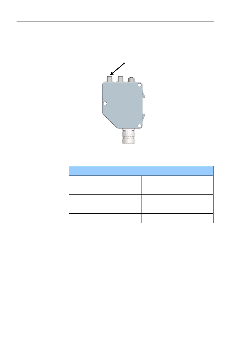
2.3 BUS lines
The PROFIBUS bus line connections of the M12 equipped
devices are constituted by a male B-coded 5 pin M12 connector
(bus in), and a female B-coded 5 pin M12 connector (bus out).
Figure 5 Orientation of M12 bus connectors
16
Table 3 Pinning M12 bus in/out connectors
Page 17

The cable gland gateway shall be equipped with twisted pair
shielded cable in accordance with EN 50170 and PROFIBUS
guidelines. The guidelines recommend a conductor area higher
than 0,34 mm
10 mm for the bus lines cables. Located inside the back cover are
four screw terminals containing the required bus line terminals
marked A and B. Cable glands not used, should be replaced with
a M16 filler plug to ensure proper sealing.
Note: Tighten all screws in the terminal, even if no cable has
been attached.
Note: The two A terminals are internally connected to each
other and the two B terminals are also connected to
each other so it does not matter to which the bus lines
are connected to.
Encoder gateway installation
2
. Permissible outer cable diameter is ø 8 mm to ø
17
Page 18

Encoder gateway installation
GSD file
Gateway functionality
GSD file
Gateway PROFIBUS DPV2
(For rotary encoders)
ENC_OB21
Gateway PROFIBUS DPV2 (For
linear encoders)
ENC_0918
2.4 Shielding philosophy
To achieve the highest possible noise immunity and resistance
against other EMI related disturbances the bus and power supply
cables shall always be shielded. The screen should be connected
to ground on both ends of the cable. In certain cases
compensation current might flow over the screen. Therefore a
potential compensation wire is recommended.
2.5 GSD file
In order to start using the PROFIBUS DP gateway, a device
description file needs to be downloaded and imported to the
configuration software. The device description file is called a
Generic Station Description file and contains the necessary
implementation parameters needed for a PROFIBUS DP device.
Available GSD files can be downloaded from
www.heidenhain.com
18
Table 4 Available GSD file for DPV2 gateway
The GSD data is saved in the PROFIBUS master and transferred
once to the gateway when the system is powered on. If the
gateway has been started with one GSD file and a new GSD file
with a different ID-number shall be used, the gateway needs to be
restarted before it can use the new GSD file.
Page 19

2.6 LED indication
Bus status
Module
Meaning
Cause
Off
Off
No power
Red
Green
No connection to other
exchange
- Bus disconnected
available/switched off
Red 2)
Red 2)
No connection to other
PROFIBUS PCB.
No connection to EnDat
Blinking 1)
Green
Parameterization or
- Configuration received
parameterization.
Green
Red
System failure
- Diagnosis exists, slave in
data exchange mode.
Green
Green
Data exchange and encoder
function properly.
Encoder gateway installation
In order to determine the status of the gateway two LEDs are
visible on the front of the gateway. The module LED indicates
status of the module itself. The bus LED indicates the status of
the bus. The table below defines the diagnostic messages using a
bi-colored red/green LED for bus and module.
Table 5 LED indication
1. The blinking frequency is 0.5 Hz. Minimal indication time is
2. Position error is when an alarm occurs in the encoder or if the
device. Criteria: No data
device. No connection
- Master not
encoder at power up.
between EnDat encoder and
configuration fault
differs from the supported
configuration.
- Parameter error in the
3 sec.
EnDat encoder is disconnected from the PROFIBUS interface
PCB.
19
Page 20
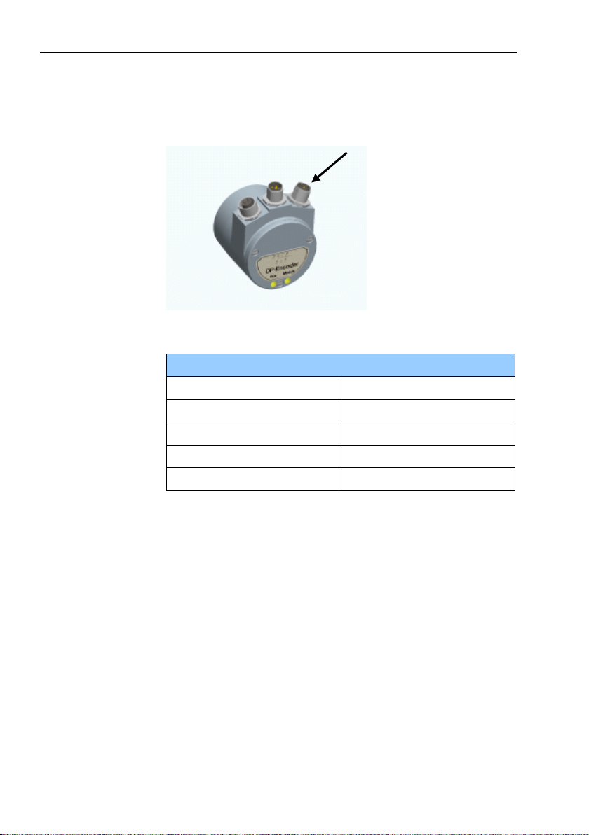
Absolute encoder installation
Screw terminals
Bus termination
Node address
switches
3 Absolute encoder installation
3.1 Settings inside the encoder
The encoder node address and bus termination must be
configured during commissioning of the device. This is done by
removing the back cover, i.e. screwing off the three screws at the
rear of the encoder.
3.1.1 Node address
The node address of the encoder can be set via two decimal
rotary switches located inside the back cover. The weighting, x10
or x1 are specified beside the switches. Permissible address
range is between 0 and 99 but the lower addresses 0 to 2 are
usually used by the master and not recommended to be used by
the device. Each address used in a PROFIBUS network must be
unique and may not be used by other devices.
The device address is only read and adopted when the encoder
power supply is switched on. A restart of the encoder is therefore
required in order to adopt changes done to the address settings.
Figure 6 PCB-view of a cable gland encoder
Example: If the node address shall be set to 85, the left(x10)
switch shall be set to 8 and the right(x1) switch shall be set to 5.
20
switch (on/off)
Page 21

3.1.2 Bus termination
Bit1
Bit2
Effect
On
On
There is a 220ohms resistor between bus A
and bus B line.
On
Off
Not a valid setting
Off
On
Not a valid setting
Off
Off
There is no resistor between bus A and bus
B line.
In a PROFIBUS net, all devices are connected in a bus structure.
Up to 32 devices (master and/or slaves) can be connected in one
segment. When more devices are needed repeaters should be
used to amplify the signals between segments. An active
termination must be added in the beginning and end of each bus
segment in order to ensure error-free operation.
In case of the encoder with cable glands such terminators are
integrated inside the back cover and can be activated via dip
switches as shown in figure 6. If the device is un-powered the A
and B lines are internally terminated by a 220Ω resistor.
Table 6 Terminating switch settings
When encoders with M12 connectors are used the termination
should be done using a terminating resistor plug.
Note: When encoders with M12 terminating resistor plugs
are used, the internal terminating switch shall not be
activated.
Absolute encoder installation
21
Page 22
Absolute encoder installation
Power supply M12 version
Function
Pin
+E Volt (9-36V)
1
Not connected
2
0 Volt
3
Not connected
4
Power supply
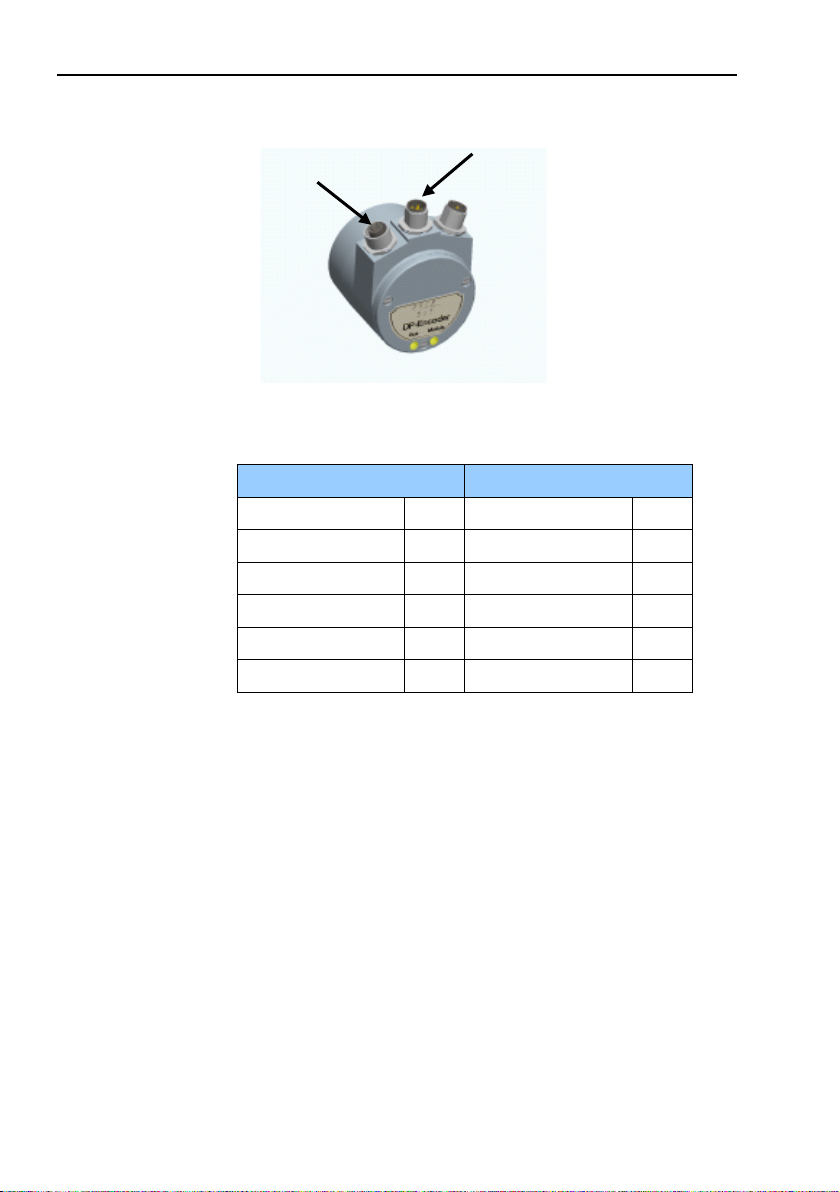
3.2 Connecting the encoder
The power supply connection of M12 equipped encoders are
constituted by a male A-coded 4 pin M12 connector.
Figure 7 Orientation of M12 power supply connector
22
Table 7 Pinning M12 power supply
Page 23

Encoders equipped with cable glands are delivered with a dust
protection foil from the factory. The protection foil needs to be
removed prior to install the cables.
It is recommended that encoders with cable gland are equipped
with a shielded power supply cable with conductor area between
2
0,34 mm
t o 1.5 mm2. Permissible outer cable diameter is
ø 6 mm to ø 8 mm for the power supply cable. Located inside the
back cover are two screw terminals containing the required power
supply terminals marked (+) and (-). In the case were the encoder
is the last node in the bus-structure and only the cable glands for
Supply and Bus-in is in use, the Bus out cable gland should be
replaced with a M16 filler plug to ensure proper sealing.
The (+) terminal shall be used to connect the +EV-line (9-36 Vdc).
The (-) terminal shall be used to connect the 0 V-line.
Figure 8 Terminal connections of power supply cables
Note: Tighten all screws in the terminal, even if no cable has
been attached.
Absolute encoder installation
23
Page 24
Absolute encoder installation
Bus in line
Bus out line
Function
Pin
Function
Pin
Not connected
1
VP
1
A 2 A
2
Not connected
3
DGND
3 B 4 B 4
Chassis
5
Chassis
5
Bus in
Bus out
3.2.1 Bus lines
Figure 9 Orientation of M12 bus connectors
24
Table 8 Pinning M12 bus in/out lines
Page 25

The cable gland encoders shall be equipped with twisted pair
shielded cable in accordance with EN 50170 and PROFIBUS
guidelines. The guidelines recommend a conductor area higher
than 0,34 mm
ø 10 mm for the bus line cables. Located inside the back cover are
four screw terminals containing the required bus line terminals
marked (A) and (B). Cable glands not used should be replaced
with a M16 filler plug to ensure proper sealing.
The (A) terminal shall be used to connect the A-line.
The (B) terminal shall be used to connect the B-line.
Figure 10 Terminal connections of bus line cables
Note: Tighten all screws in the terminal, even if no cable has
been attached.
Note: The two A terminals are internally connected to each
other and the two B terminals are also connected to
each other so it does not matter to which terminal the
bus lines are connected to.
Absolute encoder installation
2
. Permissible outer cable diameter is ø 8 mm to
25
Page 26

Absolute encoder installation
GSD file
Gateway functionality
GSD file
Absolute encoder PROFIBUS DPV2
Enc_0aaa
3.3 Shielding philosophy
To achieve the highest possible noise immunity and resistance
against other EMI related disturbances the bus and power supply
cables shall always be shielded. The screen should be connected
to ground on both ends of the cable. In certain cases
compensation current might flow over the screen. Therefore a
potential compensation wire is recommended.
3.4 GSD file
In order to start using an absolute encoder with PROFIBUS DP
interface, a device description file needs to be downloaded and
imported to the configuration software.
The device description file is called a Generic Station Description
file and contains the necessary implementation parameters
needed for a PROFIBUS DP device.
Available GSD files can be downloaded from
www.heidenhain.com.
Table 9 Available GSD file for DPV2 encoder
The GSD data is saved in the PROFIBUS master and transferred
once to the encoder when the system is powered on. If the
encoder has been started with one GSD file and a new GSD file
with a different ID-number shall be used, the encoder needs to be
restarted before it can use the new GSD file.
26
Page 27

3.5 LED indication
Bus status
Module
Meaning
Cause
Off
Off
No power
Red
Green
No connection to other
exchange
- Bus disconnected
switched off
Red 2)
Red 2)
No connection to other
and PROFIBUS PCB.
No connection to EnDat
Blinking 1)
Green
Parameterization or
- Configuration received
parameterization.
Green
Red
System failure
- Diagnosis exists, slave in
- Position error
Green
Green
Data exchange. Slave and
operation OK
Absolute encoder installation
In order to determine the status of the encoder two LEDs are
visible from the rear end of the encoder. The module LED
indicates status of the module itself. The bus LED indicates the
status of the bus. The table below defines the diagnostic
messages using a red (BUS) and a bicolor, Red/Green, LED
(MODULE).
device. Criteria :No data
device. No connection
between EnDat encoder
configuration fault
Table 10 LED indication encoder
1. The blinking frequency is 0.5 Hz. Minimal indication time is
3 sec.
2. Position error is when an alarm occurs in the encoder or if the
EnDat encoder is disconnected from the PROFIBUS interface
PCB.
- Master not available/
encoder at power up.
differs from the supported
configuration.
- Parameter error in the
data exchange mode.
27
Page 28
Configuration example
4 Configuration example
This chapter will illustrate how to set up and configure an encoder
gateway with PROFIBUS DPV2 in isochronous operation. In the
example below a Siemens Step 7 PLC and SIMATIC MANAGER
was used.
4.1 Device description file installation (GSD-file)
In order to start using an encoder gateway with PROFIBUS
interface, a device description file needs to be downloaded and
imported to the configuration software.
The latest available GSD file can be downloaded from
www.heidenhain.com.
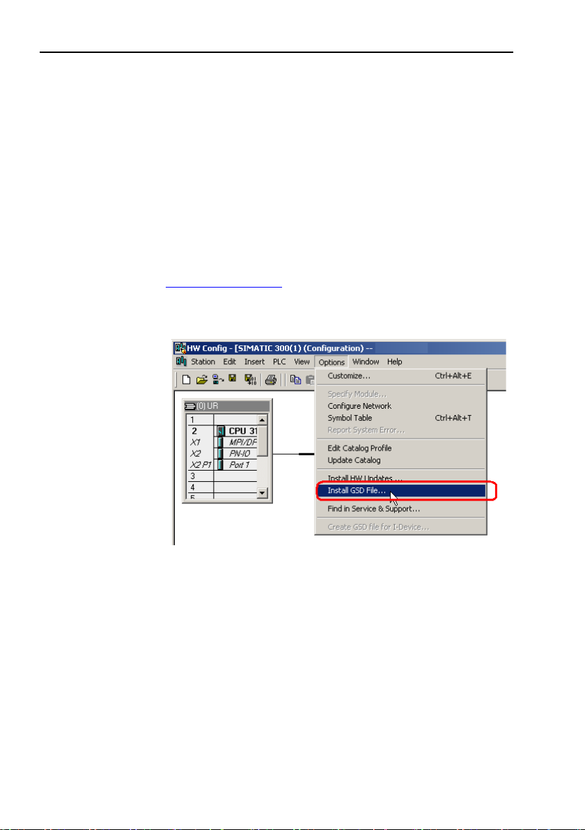
Installation of GSD-files in SIMATIC MANAGER
28
1. Select Options -> Install GSD File and click the Browse button
to navigate to the location of the GSD file. If a bitmap picture
representing the encoder is requested, make sure that the
bitmap file is located in the same folder as the GSD file. A
bitmap file is included in the zip-file avaliable from
www.heidenhain.com.
2. Select the GSD file and click the Install button to start installing
the selected GSD file.
Page 29

4.2 Setting the encoder gateway configuration
Once the GSD file has been installed, the encoder gateway can
be found in the SIMATIC MANAGER-> HW Config under
PROFIBUS DP ->Additional Field Devices->Encoders. Select the
appropriate device to be configured. Drag and drop the device
onto the PROFIBUS DP system as shown in the picture below. In
the example below, the HEIDENHAIN DPV2 Gateway was
chosen. If more than one device is connected and is to be
configured, then the following steps need to be performed once
for each connected device.
Configuration example
When dropping the encoder on the BUS a PROFIBUS address
must be assigned, naturally this address must be the same as
assigned on the hardware address switches located inside the
unit.
29
Page 30

Configuration example
If appropriate enter a name for the device.
If double clicking on the unit on the bus, the properties window
will open.
The next step is to choose the data length and the type of data
that is to be sent to and from the controller. This is done by
choosing different telegrams.
30
Page 31

Configuration example
Available telegrams for the HEIDENHAIN DPV2 Gateway can be
found by expanding the device. In the example below, standard
telegram 81 is used. Drag and drop the telegram onto slot 1 as
shown in the picture below. For more information regarding the
different telegrams refer to chapter 5.4.
Note: The steps described above needs to be performed for each
connected device.
31
Page 32

Configuration example
4.3 Setting encoder gateway parameters
To set the parameter data, choose the device and then double
click on the line according to below.
In the Properties windows that opens, open the Parameter
Assignment tab.
To set the parameter data, change the value
of the different parameters by clicking on the Value field for the
respective parameter. Please note that the parameter Class 4
Functionality must be enabled in order to use some of the
available parameters. For more information regarding this, see
chapter 8.2.
32
Page 33

Once the configuration and parameterization of the device has
been completed, the settings need to be saved and compiled.
This is done by clicking on the Save and Compile option under the
Station tab.
The settings then need to be downloaded to the controller. This is
done by clicking on the Download option under the PLC Ta b.
Configuration example
33
Page 34

Configuration example
4.4 Isochrone mode parameter settings -BUS
The Isochronous mode settings of the BUS are accessed by
double clicking on the bus in the BUS structure view. Then the
properties for DP master system will open.
Click on the Properties button.
Choose the Network Settings tab. For highest performance make
sure that 12 Mbps baud rate and DP profile is chosen. Then, click
on the options Button.
34
Page 35

Configuration example
In this view the DP cycle time as well as the time parameters can
be set. If the Slave Synchronization button is marked all slaves on
the bus will have the same time parameters. In this mode all
slaves on the BUS will sample data at the same time and the real
isochronous mode is obtained. To activate the clock synchronous
operation, mark the check boxes according to below.
Note: The steps described above needs to be performed for
each connected device.
35
Page 36

Configuration example
4.5 Isochrone mode parameter settings DPV2 slave
Double click on the slave device to open the properties window
and open the Isochronous Mode tab to change the settings.
Activate the clock synchronous operation by marking the check
box according to below.
36
The different time parameter can be set whereas the time base
parameters are controlled by the master. The individual DP slave
isochronous mode settings enable individual data sample time as
the TI can be set uniquely for each slave.
Page 37

5 PROFIBUS IO data description
5.1 Encoder profile for PROFIBUS version 4.1
The functionality of this profile is divided in two application
classes, Class 3 and
Class 4. The use of the name application class is new in this
profile and conforms to the Encoder class in the DPV0 profile.
For further information regarding the encoder functionality refer to
the device profile. The profile and PROFIBUS technical information
can be ordered at PNO in Karlsruhe, Germany
(www.profibus.com).
PROFIBUS IO data description
Figure 11 Overview of encoder profiles
37
Page 38

PROFIBUS IO data description
Significance
Abbreviation
Length (Bits)
Data type
Velocity value A
NIST_A
16
Signed
Velocity value B
NIST_B
32
Signed
Control word
G1_STW
16
Unsigned
Status word
G1_ZSW
16
Unsigned
Position value 1
G1_XIST1
32
Unsigned
Position value 2
G1_XIST2
32
Unsigned
Position value 3
G1_XIST3
64
Unsigned
Control word 2
STW2_ENC
16
Unsigned
Status word 2
ZSW2_ENC
16
Unsigned
5.2 Application class definition
HEIDENHAIN´s PROFIBUS devices can be configured as class 3
or class 4 PROFIBUS DP device according to the encoder profile
v.4.1. Class 3 offers the basic functionality and Class 4 offers the
basic functionality and additional full scaling and preset
functionality.
CLASS 3 Device with base mode parameter access and limited
CLASS 4 Device with scaling, preset and base-mode parameter
5.3 Standard signals
The table below describes the standard signals that are used to
configure the IO data.
parameterization of the device functionality.
Isochronous mode is not supported.
access. Isochronous mode is supported.
Table 11 Standard signals
38
Page 39

5.4 Standard telegrams
Telegram
Encoder gateway
Absolute encoder
Standard telegram 81
Supported
Supported
Standard telegram 82
Supported
Not supported
Standard telegram 83
Supported
Not supported
Standard telegram 84
Supported
Not supported
IO Data (word)
1 2 Set point
STW2_ENC
G1_STW
IO Data (word)
1 2 3 4 5 6 Actual value
ZSW2_ENC
G1_ZSW
G1_XIST1
G1_XIST2
Configuration of the devices is made by choosing different
telegram structures. The telegrams are used to specify the data
length and which type of data that are sent to and from the
master. The supported telegrams for the different devices are
shown in table 12 below.
Table 12 Supported telegrams
5.4.1 Standard telegram 81
Standard telegram 81 uses 4 bytes for output data from the
master to the device and 12 bytes of input data from the device to
the master.
Output data from the master:
2 bytes Control word 2 (STW2_ENC)
2 bytes Control word (G1_STW)
PROFIBUS IO data description
Input data to the master:
2 bytes Status word 2 (ZSW2_ENC)
2 bytes Status word (G1_ZSW)
4 bytes Position value 1 (G1_XIST1)
4 bytes Position value 2 (G1_XIST2)
39
Page 40

PROFIBUS IO data description
IO Data (word)
1
2
Set point
STW2_ENC
G1_STW
IO Data (word)
1 2 3 4 5 6 7
Actual value
ZSW2_ENC
G1_ZSW
G1_XIST1
G1_XIST2
NIST_A
5.4.2 Standard telegram 82
Standard telegram 82 uses 4 bytes for output data from the
master to the encoder gateway and 14 bytes of input data from
the encoder gateway to the master.
Output data from the master:
2 bytes Control word 2 (STW2_ENC)
2 bytes Control word (G1_STW)
Input data to the master:
2 bytes Status word 2 (ZSW2_ENC)
2 bytes Status word (G1_ZSW)
4 bytes Position value 1 (G1_XIST1)
4 bytes Position value 2 (G1_XIST2)
2 bytes Velocity value A (NIST_A)
Note: Telegram 82 is only supported by the encoder gateway.
It is not supported by the absolute encoder.
40
Page 41

5.4.3 Standard telegram 83
IO Data (word)
1
2
Set point
STW2_ENC
G1_STW
IO Data (word)
1 2 3 4 5 6 7
8
Actual value
ZSW2_ENC
G1_ZSW
G1_XIST1
G1_XIST2
NIST_B
Standard telegram 83 uses 4 bytes for output data from the
master to the encoder gateway and 16 bytes of input data from
the encoder gateway to the master.
Output data from the master:
2 bytes Control word 2 (STW2_ENC)
2 bytes Control word (G1_STW)
Input data to the master:
2 bytes Status word 2 (ZSW2_ENC)
2 bytes Status word (G1_ZSW)
4 bytes Position value 1 (G1_XIST1)
4 bytes Position value 2 (G1_XIST2)
4 bytes Velocity value B (NIST_B)
Note: Telegram 83 is only supported by the encoder gateway.
It is not supported by the absolute encoder.
PROFIBUS IO data description
41
Page 42

PROFIBUS IO data description
IO Data (word)
1
2
Set point
STW2_ENC
G1_STW
IO Data (word)
1 2 3 4 5 6 7 8 9
10
Actual value
ZSW2_ENC
G1_ZSW
G1_XIST3
G1_XIST2
NIST_B
5.4.4 Standard telegram 84
Standard telegram 84 uses 4 bytes for output data from the
master to the encoder gateway and 20 bytes of input data from
the encoder gateway to the master.
Output data from the master:
2 bytes Control word 2 (STW2_ENC)
2 bytes Control word (G1_STW)
Input data to the master:
2 bytes Status word 2 (ZSW2_ENC)
2 bytes Status word (G1_ZSW)
8 bytes Position value 3 (G1_XIST3)
4 bytes Position value 2 (G1_XIST2)
4 bytes Velocity value B (NIST_B)
Note: Telegram 84 is only supported by the encoder gateway.
It is not supported by the absolute encoder.
Note: In standard telegram 84, G1_XIST2 is used to transfer
error codes and optionally position values if the
measuring length exceeds 64 bits.
42
Page 43

5.5 Format of G1_XIST1 and G1_XIST2
The G1_XIST1 and G1_XIST2 signals consist of the absolute
position value in binary format. By default the G1_XIST 1 signal is
equal to the G1_XIST2 signal. The format of the actual position
values in G1_XIST1 and G1_XIST2 is shown below.
Format definition for G1_XIST1 and G1_XIST2:
• All values are presented in binary format
• The shift factor is always zero (right aligned value) for both
G1_XIST1 and G1_XIST2.
• The setting in the encoder parameter data affects the position
value in both G1_XIST1 and G1_XIST2.
• G1_XIST2 displays the error message instead of the position
value if an error occurs. See also chapter 6.4 Error Message.
Example: 25 bit multi turn absolute encoder with gateway (8192
steps per revolution, 4096 distinguishable revolutions)
M = Multi turn value (Distinguishable revolutions)
S = Single turn value (number of steps per revolutions)
PROFIBUS IO data description
Figure 12 Absolute value in G1_XIST1
Figure 13 Absolute value in G1_XIST2
43
Page 44

PROFIBUS IO data description
IO Data (word)
1 2 3
4
Format
64 bit position value
5.6 Format of G1_XIST3
G1_XIST3 is a 64 bit position value which is used to support
encoders with a resolution exceeding 32 bits.
Format definition for G1_XIST3:
• Binary format
• The actual position value is always right aligned, a shifting
factor is not used.
• The settings in the encoder parameter data affect the position
value in G1_XIST3 if Class 4 is enabled.
Table 13 Format of G1_XIST3
44
Page 45

5.7 Control word 2 (STW2_ENC)
Bit
Function
0...6
Reserved
7
Fault acknowledge
8,9
Reserved
10
Control by PLC
11
Reserved
12...15
Controller sign-of-life
Bit
Valu e
Significance
Comments
7
1
Fault acknowledge (0->1)
The fault signal is acknowledged with a
a fault depends on the type of fault.
0
No significance
10
1
Control by PLC
Control via interface. EO IO is valid.
0
No control by PLC
EO IO data not valid, except sign-of-life
12-15
Controller sign-of-life
The control word 2 (ZSW2_ENC) is referred to as the master sign
of life and it includes the fault buffer handling and Control by PLC
mechanism from PROFIdrive STW1 and the Controller Sign-OfLife mechanism from PROFIdrive STW2. This signal is mandatory
for controlling the clock synchronization.
Table 14 STW2_ENC definition
PROFIBUS IO data description
positive edge. The encoder reaction to
Table 15 Detailed assignment of control word2 (STW2_ENC)
45
Page 46

PROFIBUS IO data description
Bit
Function
0...2
Reserved
3
Fault present/No fault
4,8
Reserved
9
Control requested
10,11
Reserved
12...15
Encoder sign-of-life
Bit
Valu e
Significance
Comments
3
1
Fault present
Unacknowledged faults or currently not
fault numbers are in the fault buffer.
0
No fault
9
1
Control requested
The automation system is requested to
assume control.
0
No control requested
Control by automation system is not
by another interface.
12-15
Encoder sign-of-life
5.8 Status word 2 (ZSW2_ENC)
The status word 2 (ZSW2_ENC) is referred to as the slave’s sign
of life and it includes the fault buffer handling and Control by PLC
mechanism from PROFIdrive ZSW1 and the Slave Sign-Of-Life
mechanism from PROFIdrive ZSW2. This signal is mandatory for
controlling the clock synchronization.
Table 16 ZSW2_ENC definition
acknowledged faults are present. The
fault reaction is fault-specific and devicespecific. The acknowledging of a fault
may only be successful if the fault case
has disappeared or has been removed
before. If the fault has been removed the
encoder returns to operation. The related
Table 17 Detailed assignment of Status word 2 (ZSW2_ENC)
46
possible, only possible at the device or
Page 47

5.9 Control word (G1_STW)
Bit
Function
0...7
Function requests: Reference mark search,
measurement on the fly
8..10
Reserved
11
Home position mode (absolute/relative)
12
Request set/shift of home position (Preset)
13
Request absolute value cyclically
14
Activate parking sensor
15
Acknowledging a sensor error
The control word controls the functionality of major encoder
functions.
Table 18 G1_STW implementation requirements
Note: If the sensor parking is activated (bit 14=1) the device
is still on the bus with the slave sign of life active and
encoder error and diagnostics switched off.
PROFIBUS IO data description
47
Page 48

PROFIBUS IO data description
Bit
Function
0...7
Function status: Reference mark search,
measurement on the fly
8
Probe 1 deflected
9
Probe 2 deflected
10
Reserved, set to zero
11
Requirement of error acknowledgement detected.
12
Set/shift of home position executed
13
Transmit absolute value cyclically
14
Parking sensor active
15
Sensor error
5.10 Status word (G1_ZSW)
The status word defines encoder states, acknowledgements,
error messages of major encoder functions.
Table 19 G1_ZSW implementation requirements
Note: If bit 13 Transmit absolute value cyclically or bit 15
Sensor error is not set there is no valid value or error
code transferred in G1_XIST2.
Note: Bit 13 Transmit absolute value cyclically cannot be set
at the same time as bit 15 Sensor error as these bits
are used to indicate either a valid position value
transmission (bit 13) or the error code transmission
(bit 15) in G1_XIST2.
48
Page 49

PROFIBUS IO data description
5.11 Isochronous operation
Clock Synchronous Operation at PROFIBUS DP is done by using
the PROFIBUS DP-V2 Isochronous Mode. Clock cycle
synchronous operation in the PROFIBUS DP Isochronous Mode is
implemented by using an isochronous clock signal. This cyclic,
isochronous clock signal is transmitted as Global Control telegram
from the DP-master (class 1) to all PROFIBUS slaves. Thus, the
slaves supporting isochronous operation may synchronies their
applications (internal/Slave Clock) with the Master Clock.
Figure 14 Sequence of the DP-cycle in isochronous mode
TI (Input time)
This is the time for actual value acquisition. The time TI refers to
the end of the DP-Cycle. The minimum time for TI is 375 µs for the
gateway and 125µs for the absolute encoder. There has to be a
minimum time of 125µs between TI and TO.
TO (Output time)
Time TO refers to the start of the DP-cycle. The time TO is the
time for setpoint transfer . For the encoder and the gateway the
time TO is insignificant.
TJ (Jitter Time)
TJ mirrors the time in which the clock jitter lasts. The clock jitter is
the shifting of the Global Control (GC) telegram with respect to
time.
TDX (Data_Exchange Time)
This time is the sum of the transmission times of all
Data_Exchange telegrams for all slaves.
49
Page 50

PROFIBUS IO data description
TMSG (Message Time)
The times TMSG may elapse to handle all acyclic services
between the master and slave. These acyclic services shall be
executed after the cyclic services. To ensure an Isochronous DP
cycle this part shall be limited.
TDP (DP-Cycle Time)
TDP is the time a DP cycle lasts.
Content of a DP cycle:
SYNCH: Global_Control telegram for synchronization. The end of
the Global_Control (GC) telegram marks the beginning of a new
DP cycle.
DX: Data_Exchange
With the service Data_Exchange, user data exchange between
master and slave 1-n is executed sequentially.
MSG: acyclic services. After cyclic transmission the master may
transmit an acyclic service. e.g. parameter request via MS1/MS2
AR.
RES: Reserve
The reserve consists of the "active spar time" which is used as an
active rest (master transmits to itself) and the "passive spar time".
50
Page 51

6 Alarms and warnings
Diagnostic function
data type
Valu e
Comments
Octet
number
Header
Unsigned8
0x81
Identifier x
1
Channel
Unsigned8
0x40
Input
channel 0
2
Type of diagnosis
Unsigned8
See 6.3
3
6.1 Alarm mechanism
There are three ways to get diagnosis information from the
PROFIBUS encoder:
• By a read parameter access to the Parameter 65001 where
information on the current status of the Faults and Warnings
and the support of the individual diagnosis functions can be
read out.
• By the evaluation of the Error bit in the Sensor Status word
G1_ZSW and additionally the evaluation of the Error code
transmitted in G1_XIST2.
• By the use of the Extended Diagnosis in the Diagnosis
telegram where the diagnosis objects are transmitted by the
Channel Diagnosis mechanism further described in this
chapter.
6.2 Channel related diagnosis
The encoder diagnosis is reported to the master as channel
related diagnosis if the alarm channel control bit is set. If the
Alarm channel is switched of only the first 6 bytes of the
diagnostic telegram are realized
(Diag.Ext_Diag = 0): Station_status_1, Station_status_2,
Station_status_3,
Diag_Master_Add and Ident_Number.
The diagnostic reason is entered in turns and the length of each
entry is 3 octets
Alarms and warnings
Table 20 Channel related diagnostics
51
Page 52

Alarms and warnings
Definition
Error type
Position error
22
Memory error
24
6.3 Faults
If a fault occurs, the corresponding identifier is signaled in a
diagnostic telegram. Faults can be cleared after the sensor error is
acknowledged by the controller by setting bit 15 in the Control
word (G1_STW). A fault is only cleared when the functionality is
within the specification and the position value correct. A going
fault is indicated by a diagnostic telegram without the previously
sent fault.
Table 21 Faults
Error type: 22
Definition: Position value error
GSD entries:
Channel_Diag (22) = "Position value error"
Channel_Diag_Help (22) = The encoder has an internal error and is
not able to provide an accurate position value, change encoder"
Error type: 24
Definition: Memory error
GSD entries:
Channel_Diag (24) = "Memory error"
Channel_Diag_Help (24) = "The encoder has an internal error and
is not able to provide an accurate position value, change encoder"
52
Page 53

6.4 Error message
Supported diagnosis
Error code in
G1_XIST2
Description
Sensor group error
0x0001
The encoder fails to read the correct
position value
Memory error
0x 1001
The encoder fails to read the stored
volatile memory.
Command not supported
0x0F01
User parameter data assignment error
G1_STW and STW2_ENC.
Masters sign-of-life fault
0x0F02
The number of permissible failures the
controllers life sign was exceeded.
Diagnosis information can be obtained by monitoring of the Error
bit in the Status word G1_ZSW (bit 15) and evaluation of the error
code transmitted in G1_XIST2.
Table 22 Sensor status word
Alarms and warnings
offset or preset values from the non
or command error in commands word
53
Page 54

Acyclic parameter data
7 Acyclic parameter data
7.1 Acyclic data exchange
In addition to the cyclic data exchange, the PROFIBUS encoder
also supports acyclic data exchange. The acyclic data exchange is
transferred over the non-real time channel and is used to read out
and write status information from and to the slave device. The
acyclic data exchange is conducted in parallel to the cyclic data
communication.
Example of acyclic data:
• Reading of diagnostic
• Reading of I&M functions
• Reading of PROFIdrive parameters
7.2 Identification and Maintenance (I&M functions)
Encoders according to the encoder profile 3.162 also support I&M
functionality. The main purpose of I&M functions is to support the
end user if the device is acting faulty or missing some of its
functionality. I&M functions could be seen as an electronic
nameplate containing common information regarding the device
and its manufacturer.
According to the PROFIBUS specification all IO-devices must at
least support the following I&M functions:
• Order ID
• Hardware Version
• Software Version
• Product type
• Manufacturer ID
For more information regarding additional I&M supported
functions refer to chapter 8.14.6.
54
Page 55

7.3 Base mode parameter access
Write of Preset value, parameter 65000 parameter request
Request reference
0x00
Request ID
0x02
0x02->Change value,
0x 01->read value
DO-ID (axis)
0x 01
Drive object ID
No of parameters
0x 01
Attribute
0x 10
0x 10->value
No of elements
0x00
Parameter number
0xFDE8
Parameter 65000
Sub index
0x0000
Format
0x04
Data type integer 32
Number of values
0x 01
7.3.1 General characteristics
A single acyclic parameter can be transmitted in one access. A
parameter access can be up to 240 bytes long.
7.3.2 Parameter requests and responses
Request header: Request ID, DO-ID and number of parameters of
the access.
Parameter address: One address for each parameter, if several
parameters are accessed.
Parameter value: If the Request ID is 0x02 (change value) the
value is set in the request and if the Request ID is 0x01 (request
value), the value appears in the reply.
7.3.3 Changing the preset value
The table below shows the structure of a change value request.
Acyclic parameter data
Table 23 Write of preset value
55
Page 56

Acyclic parameter data
Read of preset value, parameter 65000, parameter request
Request reference
0x00
Request ID
0x 01
0x 01->read value
DO-ID (axis)
0x 01
Drive object ID
No of parameters
0x 01
0x01 Read one parameter
Attribute
0x 10
0x 10->value
No of elements
0x00
Parameter number
0xFDE8
Parameter 65000
Sub index
0x0000
Read of preset value, parameter 65000, parameter response
Request reference
0x00
mirrored
Response ID
0x 01
0x 01->read value
DO-ID (axis)
0x 01
mirrored
No of parameters
0x 01
Format
0x04
0x04=data type unsigned 32
No of values
0x 01
Values or errors
0x00,0x00x,
0x00,0x64
Preset value 100
7.3.4 Reading the preset value
The tables below show the structure of a read value request.
Table 24 Read of preset value, parameter request
Table 25 Read of preset value, parameter response
56
Page 57

7.4 Detailed description of supported parameters
7.4.1 Parameter 918, read only
918 unsigned int, presents the node address of the device.
7.4.2 Parameter 922, read only
922 unsigned int, presents which telegram is used. Telegram
81, 82, 83 or 84 is possible.
7.4.3 Parameter 925, read/write
925 unsigned int, maximum allowed MLS (Master sign-of-life)
error. Parameter 925 may be used to set a maximum on how
many consecutive Sign-of-life failures may occur.
7.4.4 Parameter 964, read only
964 unsigned int, Device indentification
964[0] = Manufacturer Id. This is set during manufacturing of the
encoder.
964[1] = 0 DU Drive unit type, always set to 0.
964[2] = 201 Software version
964[3] = 2009 Software year
964[4] = 2805 Software day and month
964[5] = 1 Number of drive objects (D
7.4.5 Parameter 965, read only
965 OctetString 2, Encoder profile number
965[0] =0x3D Encoder profile number
965[1] = 31 or 41 Encoder profile version, set by customer
(user_parameters)
7.4.6 Parameter 971, read/write
971 unsigned int, Store the local parameter set to a non volatile
memory. Preset value is saved when writing value 1 and is set to
0 by the encoder firmware when finished. This means that the
preset value has been saved when reading back value 0.
7.4.7 Parameter 974, read only
9 74 unsigned int
974[0] = 96 Max array length supported by parameter channel.
974[1] = 1 Numbers of multi parameters, 1 = no support of
multi parameters.
974[2] = 1000 max time to process parameter request,
n x 10 ms.
Acyclic parameter data
57
Page 58

Acyclic parameter data
7.4.8 Parameter 975, read only
975 unsigned int, Encoder object identification
975[0] = Manufacturer Id, Set in the production.
975[1] = 7011 DO type
975[2] = 201 Software version
975[3] = 2009 Software year
975[4] = 2805 Software day and month
975[5] = 0x0005 Profidrive DO type class 5 = encoder interface
975[6] = 0x8000 Profidrive SUB class 1, Encoder application
class 4 supported.
975[7] = 0x0001 Drive object Id (DO ID).
7.4.9 Parameter 979, read only
979 unsigned long, Sensor format
979[0] = 0x00005111 Number of index describing encoders,
Numbers of described encoders, Version of parameter structure
979[1] = 0x80000000 Sensor type
Bit 31 = 1 if configuration and parameterization is OK
Bit 0 = 0 Rotary encoder, Bit 0 = 1 linear encoder
Bit 1 = 0 always set to 0
Bit 2 = 0 32 bit data, Bit 2 = 1 64 bit data
979[2] = 8192 Encoder scaled resolution
979[3] = 0 Shift factor for G1_XIST1. Always set to 0.
979[4] = 0 Shift factor for G1_XIST2. Always set to 0.
979[5] = 1 or 4096 Singleturn = 1, Multiturn = 4096
979[6] = 0
979[7] = 0
979[8] = 0
979[9] = 0
979[10] = 0
58
Page 59

7.4.10 Parameter 980, read only
980[0] = 918
980[8] = 979
980[16] = 65002
980[1] = 922
980[9] = 61000
980[17] = 65003
980[2] = 925
980[10] = 61001
980[3] = 964
980[11] = 61002
980[4] = 965
980[12] = 61003
980[5] = 971
980[13] = 60004
980[6] = 974
980[14] = 65000
980[7] = 975
980[15] = 65001
65001[0] = 0x000C0101
Header, Version of parameter structure and numbers of
indexdescribing the encoder.12 index and version 1.01
65001[1] = Operating status
(Bit 4 alarm channel control is always set with profile
version 4.x)
65001[2] = Alarm
65001[3] = Supported alarms
65001[4] = Warning
65001[5] = Warnings supported
65001[6] = 0x00000401
Encoder profile version. Always set to this value.
65001[7] = Operating time
65001[8] = Offset value
65001[9] = Singleturn value,
Scaled value
65001[10] =
Total measuring length, scaled value (Linear = 1)
65001[11] =
Velocity measuring unit, see chapter 8.10.
This parameter shows the supported parameters
980 unsigned int
7.4.11 Parameter 65000 read/write
Used with telegram 81-83
65000 signed long, preset value 32 bit.
7.4.12 Parameter 65001, read only
Used with telegram 81-84
65001 unsigned long
Acyclic parameter data
59
Page 60

Acyclic parameter data
65003[0]=
0x0000000000040101 Header Version of parameter structure and
numbers of index describing encoder. 4 index and version 1.01
65003[1]=
Offset value 64 bit
65003[2]=
Singleturn value 64 bit, scaled value
65003[3]=
total measuring range in measuring units 64 bit, scaled value (Linear =1)
Hardware components
Master
SIEMENS S7F-CPU
CPU 315F-2 PN/DP
Slave device
PROFIBUS encoder
Software components
SIMATIC STEP 7
V5.4 + SP5
GSD file for absolute
encoder
GSD Enc_0aaa.gsd
7.4.13 Parameter 65002, read/write
Used with telegram 84
65002 signed long long, Preset value 64 bit.
7.4.14 Parameter 65003, read only
Used with telegram 84
65003 unsigned long long,
7.5 Example of reading and writing to a parameter
This is an example of S7 blocks used for reading and writing to
parameter 65000 (preset value). Experience with S7
programming and Statement List programming language STL is
required.
Table 26 Used hardware components
Table 27 Used software components
60
Page 61

7.5.1 Used blocks
Acyclic parameter data
Write record block SFB53 WRREC
Read record block SFB52 RDREC
Instance data blocks DB3 and DB4
Request data block DB1
Response data block DB2
Organization blocks OB1, OB82 and OB86
SFB52
SFB52 is standard S7 block for reading parameters.
SFB53
SFB53 is standard S7 block for writing parameters.
DB1
DB1 is the request data block.
Figure 15 DB1, request data block
DB2
DB2 is the response data block.
Figure 16 DB2, response data block
61
Page 62

Acyclic parameter data
DB3
DB3 is the instance data block SFB52
Figure 17 DB3, instance data block of SFB52
DB4
DB4 is the instance data block of SFB53
Figure 18 DB4, instance data block of SFB53
62
Page 63

Acyclic parameter data
OB1
OB1 controls the read and write operation
Figure 19 OB1, read and write operation
63
Page 64

Acyclic parameter data
Parameter
Declaration
Data type
Description
REQ
INPUT
BOOL
REQ=1 Enables data transfer
ID
INPUT
DWORD
Logical address of the PROFIBUS
module address 2039)
MLEN*
INPUT
INT
Maximum length of the record
information in bytes.
VALID
OUTPUT
BOOL
New record has been received
and is valid
BUSY
OUTPUT
BOOL
Busy=1 during read operation
ERROR
OUTPUT
BOOL
Error=1 read error
STATUS
OUTPUT
DWORD
Block status or error code
LEN*
OUTPUT
INT
Length of record information
RECORD
IN_OUT
ANY
Target area for the record
Parameter
Declaration
Data type
Description
REQ
INPUT
BOOL
REQ=1 Enables data transfer
ID
INPUT
DWORD
Logical address of the PROFIBUS
module address 2039)
LEN*
INPUT
INT
Length of the record information
in bytes.
DONE
OUTPUT
BOOL
Data record was transferred
BUSY
OUTPUT
BOOL
Busy=1 during write operation
ERROR
OUTPUT
BOOL
Error=1 write error
STATUS
OUTPUT
DWORD
Block status or error code
RECORD
IN_OUT
ANY
Data record
Parameters of SFB52
Table 28 Parameters of SFB52
Parameters of SFB53
DP module or sub module (PAP-
Table 29 Parameters of SFB53
64
DP module or sub module (PAP-
Page 65

Acyclic parameter data
Diagnostics address of slot 1
Figure 20 Diagnostic address of slot 1
Variable table
With the variable table the user can monitor and modify variables.
Figure 21 Variable table
65
Page 66

Functionality in the PROFIBUS DPV2 device
Function
Note/Remarks
Code sequence
Class 4 functionality
G1_XIST1 Preset control
Scaling function control
Alarm channel control
Compatibility mode
Preset value
Preset value 64 bit
Only supported by the
encoder gateway
Measuring units per revolution
Total measuring range
Measuring units per revolution 64 bit
Only supported by the
encoder gateway
Total measuring range 64 bit
Only supported by the
encoder gateway
Maximum master sign-of-life failures
Velocity measuring unit
Only supported by the
encoder gateway in DPV1
Encoder profile version
Operating time
Supported by absolute
only in DPV1
Offset value
Offset value 64 bit
Only supported by the
encoder gateway
8 Functionality in the PROFIBUS DPV2 device
This chapter describes the functions that have been implemented
in PROFIBUS DPV2 devices from HEIDENHAIN. The table below
shows the supported functions and if there are any limitations.
Table 30 Supported functions
66
encoder and encoder gateway
Page 67

8.1 Code sequence
Attribute
Meaning
Valu e
CW
Increasing position values with clockwise
rotation (seen from shaft side)
0
CCW
Increasing position values with counter
clockwise rotation (seen from shaft side)
1
Attribute
Meaning
Valu e
Enable
Scaling/Preset/ code sequence control
enabled
1
Disable
Scaling/Preset/ code sequence control
disabled
0
The code sequence defines whether the absolute position value
should increase during clockwise or counter clockwise rotation of
the encoder shaft seen from flange side. The code sequence is by
default set to increase the absolute position value when the shaft
is turned clockwise (0).
Table 31 Code sequence attributes
Note: The position value will be affected when the code
sequence is changed during operation. It might be
necessary to perform a preset after the code sequence
has been changed.
Note Code sequence for the linear scale is not supported by
the gateway.
8.2 Class 4 functionality
This parameter enables or disables the measuring task functions
Scaling, Preset and Code sequence. If the function is enabled,
scaling and Code sequence control affects the position value in
G1_XIST1, G1_XIST2 and G1_XIST3. A preset will in this case
always affect G1_XIST2 and G1_XIST3 but if the parameter
G1_XIST1 Preset control is disabled the preset will not affect the
position value in G1_XIST1.
Functionality in the PROFIBUS DPV2 device
Table 32 Class 4 functionality attributes
67
Page 68

Functionality in the PROFIBUS DPV2 device
Attribute
Meaning
Valu e
Enable
G1_XIST1 is affected by a preset
command
0
Disable
Preset does not affect G1_XIST1
1
Attribute
Meaning
Valu e
Enable
Scaling function is enabled
1
Disable
Scaling function is disabled
0
8.3 G1_XIST1 Preset control
This parameter controls the effect of a preset on the G1_XIST1
actual value.
If Class 4 functionality is activated and G1_XIST1 Preset control is
disabled, the position value in G1_XIST1 will not be affected by a
Preset.
Table 33 G1_XIST1 Preset control attributes
Note: This parameter is disabled by setting the value to 1.
Note: There is no functionality of this parameter if the class 4
functionality parameter is disabled.
8.4 Scaling function control
This parameter enables or disables the Scaling function of the
encoder.
Table 34 Scaling function control attributes
Note: Class 4 functionality must be enabled to use this
parameter
68
Page 69

Functionality in the PROFIBUS DPV2 device
Attribute
Meaning
Valu e
Enable
Profile specific diagnosis is switched on
1
Disable
No profile specific diagnosis(default)
0
8.5 Alarm channel control
This parameter enables or disables the encoder specific Alarm
channel transferred as Channel Related Diagnosis. This
functionality is used to limit the amount of data sent in
isochronous mode.
If the value is zero (default value) only the communication related
alarms are sent via the alarm channel. If the value is one (1) also
encoder profile specific faults and warnings are sent via the alarm
channel.
Table 35 Alarm channel control attributes
69
Page 70

Functionality in the PROFIBUS DPV2 device
Attribute
Meaning
Valu e
Enable
Compatibility with encoder profile v3.1
0
Disable
No backward compatibility (default)
1
Function
Compatibility mode enabled
(=0)
Compatibility mode disabled
(=1)
Control by PLC
Ignored, the control word
supported and is set to 0.
Supported
User parameter
Supported
Not supported, one sign-of-life
life sign monitoring.
User parameter
Supported
Not supported, the application
parameter
P965 Profile version
31 (v3.1)
41 (v4.1)
8.6 Compatibility mode
This parameter defines if the encoder should run in a mode
compatible to Version 3.1 of the Encoder Profile. See below for an
overview of functions affected when the compatibility mode is
enabled.
Table 36 Compatibility mode attributes
(STW2_ENC)
(G1_STW) and setpoint values
are always valid. Control
requested (ZSW2_ENC) is not
Maximum master
sign-of-life failures
Alarm channel
control
Table 37 Compatibility mode definition
failure tolerated. PROFIdrive
P925 is optional to control the
alarm channel is active and
controlled by a PROFIdrive
70
Page 71

8.7 Preset value
The preset value function enables adaptation of the position value
from the encoder to a known mechanical reference point of the
system. The preset function sets the actual position of the
encoder to zero (= default value) or to the selected preset value. A
preset value can be set more than once and it can be stored to
the non-volatile memory using PROFIdrive parameter 971.
The preset function has an absolute and a relative operating mode
selectable by bit 11 in the Control word (G1_STW). Bit 11 and bit
12 in the Control word controls the preset in the following way.
Normal operating mode: Bit 12=0
In this mode, the encoder will make no change in the output
value.
Preset mode absolute: Bit 11 =0, Bit 12 = 1
In this mode, the encoder reads the current position value and
calculates an internal offset value from the preset value and the
current position value. The position value is then shifted with the
calculated offset value to get a position value equal to the preset
value. No preset will be made if a negative preset value is used
while trying to initiate an absolute preset.
Preset mode relative: Bit 11 =1, Bit 12 = 1
In this mode the position value is shifted by the preset value,
which could be a negative or a positive value set by encoder
parameter 65000 or 65002.
Functionality in the PROFIBUS DPV2 device
71
Page 72

Functionality in the PROFIBUS DPV2 device
Parameter
Meaning
Data type
Preset value
The preset value for encoders with a
measuring range of maximum 32 bits
Integer32
Preset value 64
The preset value for encoders with a
measuring range exceeding 32 bits
Integer64
The steps below should be followed from the master when
modifying the Preset value parameters:
• Read the requested Preset value parameter and check if the
returned value meets the application requirements. If not,
proceed with the following steps.
• Write the Preset value into the individual parameter.
• Store the value in the non volatile memory by PROFIdrive
parameter 971 if the value should be valid also after the next
power on sequence.
Table 38 Preset value parameters
Note: The preset function should only be used at encode
standstill
Note: The number of possible preset cycles is unlimited.
Note: If scaling is used the preset function shall be used after
the scaling function to ensure that the preset value is
entered in the current measuring unit.
Note: There is no preset activated when the preset value is
written to the encoder. The preset function is controlled
by bits in the control and status words (G1_STW and
G1_ZSW) and bit in the operating parameters. The
preset value is used when a preset is requested by bit
12 in the Control word (G1_STW).
72
Page 73

8.8 Scaling function parameters
Parameter
Meaning
Data type
Measuring units per
revolution
The single turn resolution in
measuring steps
Unsigned 32
Measuring units per
The single turn resolution in
resolution exceeding 32 bits.
Unsigned 64
The scaling function converts the encoder’s physical absolute
position value by means of software in order to change the
resolution of the encoder. The scaling parameters will only be
activated if the parameter Class 4 functionality and Scaling
function control are enabled. The permissible value range for the
scaling is limited by the resolution of the encoder.
Singleturn encoders up to 31 bit and multiturn encoders up to 37
bits resolution are
supported by the encoder gateway. When using encoders with
higher resolution than 31 bits together with the encoder gateway,
telegram 84 must be used.
8.8.1 Measuring units per revolution
This parameter sets the singleturn resolution of the encoder. In
other words it is the number of different measuring steps during
one revolution of the encoder.
Example: For a 13-bit encoder with a single turn resolution of
13 bits the permissible value range for "Measuring
units per revolution" is between 20 and 213 (8192).
Functionality in the PROFIBUS DPV2 device
revolution 64 bit
Table 39 Single turn scaling parameters
measuring steps for encoders with a
Note: The parameter Measuring units per revolution 64 bit is
only supported by the encoder gateway.
Note: After downloading new scaling parameters, the preset
function must be used to set the encoder starting
point to absolute position 0 or to any required starting
position within the scaled operating range.
73
Page 74

Functionality in the PROFIBUS DPV2 device
Parameter
Meaning
Data type
Total measuring range
in measuring units
The total measuring range in
measuring steps
Unsigned 32
Total measuring range
64 bit
The total measuring range for
32 bits
Unsigned 64
8.8.2 Total measuring range
This parameter sets the total measuring range of the encoder. The
total measuring range is calculated by multiplying the single turn
resolution with the number of distinguishable revolutions.
in measuring units
encoders with a range exceeding
Table 40 Total measuring range
Note: The parameter Total measuring range in measuring
units 64 bit is only supported by the encoder gateway.
Example: The total measuring range for a 25 bit multi turn
encoder with a 13 bit single turn resolution and a 12 bit
multi turn resolution, the permissible value range for
the "Total measuring range" is between 2
(33 554 432).
The total measuring range is calculated as below:
Measuring units per revolution x Total
measuring range = 8192
If the encoder gateway is used and the total measuring range is
higher than 31 bit, telegram 84 and acyclic encoder parameter
65002 and 65003 must be used. In this case the 64 bit values are
used and the 32 bit values are set to zero (0) by the encoder.
Note: Telegram 84 and parameter 65002 and 65003 are only
supported by the encoder gateway.
0
and 225
(213) x 4096 (212) = 33554432
74
Page 75

Functionality in the PROFIBUS DPV2 device
The devices have two different operating modes, depending on
the specified measuring range. When the device receives a
parameter message, it checks the scaling parameters if a binary
scaling can be used. If binary scaling can be used, the device
selects operating mode A (see following explanation). If not,
operating mode B is selected.
A. Cyclic operation (Binary scaling)
Cyclic operation is used when operating with 2X number of turns
(2, 4, 8, 16, 32, 64, 128, 256, 512, 1024, 2048. 4096.. number of
turns). If the desired total measuring range is equal to the
specified single turn resolution * 2X (where x<= 12) the encoder
operates in endless cyclic operation (0 - max - 0 -max..). If the
position value increases above the maximum value by rotating the
encoder shaft, the encoder continues from 0.
Example of a cyclic scaling:
Total measuring range= Measuring units per revolution x number
of revolutions
Measuring units per revolution = 1000
Number of revolutions= 32(=25=2x2x2x2x2)
(32 equals 25 means that a binary scaling will be used)
Total measuring range = 1000 x 32 =32000
Figure 22 Cyclic scaling
75
Page 76

Functionality in the PROFIBUS DPV2 device
B. Non-cyclic operation
If the desired total measuring range is not equal to the specified
single turn resolution * 2X (where x<= 12) the encoder operates
in non-cyclic operation. The non-cyclic operation is affected by the
parameter G1_XIST 1 Preset control as described below.
G1_XIST1 Preset control=Enabled
If the position value increases or decreases outside the maximum
value or below 0 with the parameter G1_XIST 1 Preset control
enabled, the device outputs the maximum position value within
the scaled total range for both position values G1_XIST 1 and
G1_XIST 2.
Example of non-cyclic scaling with G1_XIST 1 Preset control
enabled:
Total measuring range= Measuring units per revolution x number
of revolutions
Measuring units per revolution = 10 0
Number of revolutions= 50
(=50 is not equal to 2X where x<=12 means that a non cyclic
scaling will be used)
Total measuring range = 100 x 50 = 5000
Figure 23 Non-cyclic scaling G1_XIST 1 Preset control enabled
76
Page 77

Functionality in the PROFIBUS DPV2 device
G1_XIST1 Preset control = disabled
With the parameter G1_XIST 1 preset control disabled, and if the
position value increases or decreases outside the maximum value
or below 0, the device will output the maximum position value
within the scaled total range for the position value G1_XIST 2. The
position value G1_XIST 1 is not limited to the scaled total range.
For the position value G1_XIST 1, the device will continue to
output a position value within the encoder’s total measuring range
(up to 33554432 positions for a 25 bit encoder)
Example of non-cyclic scaling G1_XIST 1 Preset control
disabled:
Measuring units per revolution = 10 0
Total measuring range = 5000
(number of revolutions 50)
Figure 24 Non-cyclic scaling G1_XIST 1 Preset control disabled
77
Page 78

Functionality in the PROFIBUS DPV2 device
Parameter
Meaning
Valu e
Maximum master
sign-of-life failures
The number of permissible failures of
the masters life sign
1..255
LSB
MSB
Handling 64 bits data
Siemens hardware configuration tool does not support 64 bit data
type, so when writing larger numbers than 32 bit into the
configuration tool, this needs to be done according to below:
Example:
Total measuring range in measuring units = 2
36
= 6871947673610 = 0x00000010 00000000
2
4 byte 4 byte
Take the 4 least significant bytes (LSB) above and convert to
decimal:
0x00 00 00 00 = 0 = Total measuring range LSB
Then take the 4 most significant bytes (MSB) above and convert
to decimal:
0x00 00 00 10 = 16 = Total measuring range MSB
In the configuration software enter the decimal values:
Total measuring range LSB = 0
Total measuring range MSB = 16
8.9 Maximum master sign-of-life failures
With this parameter the number of allowed failures of the
master´s sign of life is defined. The default value is one (1).
36
Table 41 Maximum master sign-of-life parameter
Note: This parameter is only supported in compatibility
mode.
78
Page 79

Functionality in the PROFIBUS DPV2 device
Parameter
Meaning
Valu e
Velocity measuring
units
Definition of the units for the encoder
velocity value
See table 41.
Velocity measuring units
Valu e
Steps/s
0
Steps/100ms
1
Steps/10 ms
2
RPM
3
8.10 Velocity measuring units
This parameter defines the coding of the velocity measuring units
used to configure the signals NIST_A and NIST_B which are
included in Telegram 82-84. Standard telegram 81 has no velocity
information included and the encoder does not use the velocity
unit information in this case. The encoder gateway supports
Telegram 82, 83 and 84 and needs a declaration of the velocity
measuring unit.
Table 42 Parameter Velocity measuring unit
Table 43 Coding of velocity measuring units
79
Page 80

Functionality in the PROFIBUS DPV2 device
Bits
Meaning
0..7
Profile version, least significant number (value range:0-99),
decimal coding
8..15
Profile version, most significant number (value range:0-99),
decimal coding
16..31
Reserved
The velocity calculations are made with a maximum of 19 bits
resolution. If the resolution is higher than 219, the value used for
velocity calculations is automatically reduced to 2
Example: For an encoder gateway used with a 37 bit multi turn
encoder with a 2
multi turn resolution, the maximum single turn value
for velocity calculations will be 2
encoder the maximum resolution can be up to 31 bit,
but the value used for velocity calculations will in this
case also be 2
Note: In case of the step/s unit, an average is made over
200ms and the value is multiplied by 5.
Note If scaling has been set on the device the velocity
calculation is based on the scaled position value.
Consequently the accuracy of the velocity value is
dependent of the scaling set to the device.
Note: The velocity function is only supported when using the
encoder gateway and DPV1 functionality.
8.11 Encoder profile version
The encoder Profile Version is the version of the encoder profile
document implemented in the encoder. This parameter is not
affected by the Compatibility mode settings.
25
single turn resolution and a 2
19
. For a single turn
19
.
19
.
12
Table 44 Encoder profile version parameter
80
Page 81

8.12 Operating time
Parameter
Meaning
Data type
Operating time
The accumulated power on time
Unsigned32
Parameter
Meaning
Data type
Offset value
The offset value for encoders with a
measuring range of maximum 32 bits
Integer32
Offset value 64 bit
The offset value for encoders with a
measuring range exceeding 32 bits.
Integer64
The operating time monitor stores the operating time for the
device in operating hours. The operating time is saved every six
minutes in the non-volatile memory in the device. This happens as
long as the device is powered on.
If the operating time function is not used the operating time value
is set to the maximum value (0xFFFF FFFF).
Table 45 Operating time parameter
Note: The parameter Operating time is only supported by
the absolute encoder and encoder gateway in DPV1.
8.13 Offset value
The offset value is calculated in the preset function and shifts the
position value with the calculated value. The offset value is stored
in a non volatile memory and can be read from the encoder at any
time. The data type for the offset value is a 32 bit or 64 bit binary
value with sign, whereby the offset value range is equal to the
measuring range of the device.
The preset function is used after the scaling function. This means
that the offset value is indicated according to the scaled resolution
of the device.
Functionality in the PROFIBUS DPV2 device
Table 46 Off set value parameter
Note: The offset value is read only and cannot be modified
by a parameter write access.
81
Page 82

Functionality in the PROFIBUS DPV2 device
Prm.No
Significance
Data type
Read/Write
918
Node address
Unsigned16
R
922
Telegram selection
Unsigned16
R
925
Number of Controller sign-of-life
failures which may be tolerated
Unsigned16
R/W
964
Device identification
Array [n]
Unsigned16
R
965
Encoder profile number
Octet string 2
R
971
Transfer to non-volatile memory
Unsigned16
W
9 74
Base mode parameter access
service identification
Array[n]
Unsigned16
R
975
Encoder object identification
Array[n]
Unsigned16
R
979
Sensor format
Array[n]
Unsigned32
R
980
List of supported parameters
Array[n]
Unsigned16
R
8.14 Acyclic data
HEIDENHAIN PROFIBUS DPV2 devices support the following
acyclic data exchange functions.
8.14.1 PROFIdrive parameters
The encoder profile V4.1 has adopted certain standard PROFIdrive
parameter. The HEIDENHAIN devices support the following
PROFIdrive parameters:
Table 47 Supported PROFIdrive parameters
82
Page 83

8.14.2 Encoder parameter numbers
Prm.No
Significance
Data type
Read/
Write
Note
65000
Preset value
Integer32
R/W
65001
Operating status
Array[n]
Integer32
R 65002
Preset value 64 bit
Integer64
R/W
Only supported by
the encoder gateway
65003
Operating status 64 bit
Array[n]
Integer64
R
Only supported by
the encoder gateway
The table below specifies the encoder specific parameter that is
supported by the HEIDENHAIN PROFIBUS DPV2 devices.
Table 48 Encoder specific parameter
Note: The parameters 65000 and 65003 are not supported by
the absolute encoder.
Functionality in the PROFIBUS DPV2 device
83
Page 84

Functionality in the PROFIBUS DPV2 device
PNU
65000
Significance
Preset value
Data type
Integer32
Access
Read and write
Validity range
Profile specific
Explanation
The preset value sets the value for the preset function. The
start up if stored.
PNU
65002
Significance
Preset value 64 bit
Data type
Integer64
Access
Read and write
Validity range
Profile specific
Explanation
The preset value sets the value for the preset function. The
start up if stored.
8.14.3 Parameters 6500 and 65002 -Preset value
The parameter 65000 and 65002 sets the value for the preset
function. The parameter 65002 should be used if the preset value
exceeds 32 bits. For more information regarding the Preset
function control, see chapter 8 . 7.
preset value can be stored in the non-volatile memory by
PROFIdrive parameter 971 and will be reloaded at each
Table 49 Structure of parameter 65000 Preset value
preset value can be stored in the non-volatile memory by
PROFIdrive parameter 971 and will be reloaded at each
Table 50 Structure of 65002 Preset value 64 bit
84
Page 85

Functionality in the PROFIBUS DPV2 device
PNU
65001
Significance
Encoder operating status
Data type
Array[n] Integer32
Access
Read
Validity range
Profile specific
Explanation
The operating status displays the status of the encoder.
Sub index
Meaning
Note/limitations
0
Header
1
Operating status
2 Faults
3
Supported Faults
4 Warnings
5 Supported warnings
6
Encoder profile version
7
Operating time
Only supported in DPV1 for
absolute encoder
8
Offset value
9
Measuring units per revolution
10
Total measuring range in measuring
units
11
Velocity measuring unit
Only supported in DPV1 for
the encoder gateway
8.14.4 Parameter 65001 operating status parameter structure
This parameter structure is a read only structure where
information on the Encoder operating status can be found. It is a
complement to the PROFIdrive parameter 979 described in the
Profile for Drive Technology, PROFIdrive V4.1, order nr 3.172
available from PROFIBUS and PROFINET International.
Table 51 Structure of 65001 Encoder operating status
Table 52 Detailed structure of 65001 Operating status
the encoder gateway and the
85
Page 86

Functionality in the PROFIBUS DPV2 device
Bits
Definition
0
Code sequence
1
Class 4 functionality
2
G1_XIST1 Preset control
3
Scaling function control
4
Alarm channel control
5
Compatibility mode
6..7
Reserved for the encoder manufacturer
8..31
Reserved for future use
Sub index 1: Operating status
In sub index 1 the status of different encoder functions can be
read out. The mapping of the respective functions is according to
the table below.
Table 53 Parameter 65001 Sub index 1: Operating status
86
Page 87

Functionality in the PROFIBUS DPV2 device
PNU
65003
Significance
Encoder operating status 64 bit
Data type
Array[n] Integer64
Access
Read
Validity range
Profile specific
Explanation
The operating status displays the status of the encoders
Sub index
Meaning
0
Header
1
Offset value 64 bit
2
Measuring units per revolution 64 bit
3
Total measuring range in measuring units 64 bit
8.14.5 Encoder specific parameter 65003- Operating status 64 bit structure
The parameter structure 65003 is only supported by the encoder
gateway and is a read only structure where information on the 64
bit parameter values can be found.
Table 54 Structure of 65003 Operating status 64 bit
Table 55 Structure of 65003 Operating status 64 bit
Note: The parameter 65003 is only supported by the encoder
gateway.
87
Page 88

Functionality in the PROFIBUS DPV2 device
I&M parameter
Octets
Comment
Header
Manufacturer specific
10
Not used
I&M block
MANUFACTURER_ID
2
Manufacturer Id
ORDER_ID
20
Encoder part number
SERIAL_NUMBER
16
Encoder serial number
HARDWARE_REVISION
2
Not used
SOFTWARE_REVISION
4
Software revision
REVISION_COUNTER
2
Not used
PROFILE_ID
2
Encoder profile number
PROFILE_SPECIFIC_TYPE
2
Type of encoder
IM_VERSION
2
Version of the I&M profile
IM_SUPPORTED
2
Value=0 means support of I&M
8.14.6 I&M functions
In addition to the PROFIdrive parameter 964, Device identification,
I&M functions are supported by the devices. The I&M functions
can be accessed with data set index 255. The following I&M
functions are supported.
Table 56 Supported I&M functions
88
Page 89

Encoder state machine
9 Encoder state machine
89
Page 90

Encoder state machine
9.1 Normal operation state
9.1.1 Profile version 4.x
If using encoder complying with encoder profile v4.1, then bit 10
Control by PLC in Control word 2 needs to be set before the data
in Control word is valid. If not set, Control word is not used by the
encoder firmware.
9.1.2 Profile version 3.x
If using encoders complying with encoder profile 3.x, the data in
Control word is always valid and bit 9 Control requested in Status
word 2 is always cleared.
9.1.3 Profile version 3.x and 4.x
When using telegram 81-83 and Control word bit 13 Request
absolute value cyclically is set, then Status word bit 13 Transmit
absolute value cyclically is set. Status word bit 13 is cleared (bit
13=0) when Control word bit 13 is cleared. Status word bit 13 is
always cleared, when using telegram 84 due to the fact that no
absolute value is sent in G1_XIST2.
9.2 Parking state
This state can be reached from any other state. The position value
in G1_XIST1, G1_XIST2 and G1_XIST3 are set to zero. Errors are
cleared and alarms are disabled in parking mode.
9.3 Set/shift home position (Preset)
The Set/shift home position is initiated when Control word bit 12
Request set/shift of home position is set. In this case the Status
word bit 12 Set/shift of home position executed is set to 1. In
order to initiate a set/shift home position, Class 4 functionality
must be enabled (see chapter 8.2), otherwise there will be an
error in G1_XIST2.
9.3.1 Preset depending on different telegrams
When using standard telegram 81-83, the acyclic encoder
parameter 65000 Preset value 32 bit shall be used to set a preset
value (<=32 bit) for the encoder. If the acyclic encoder parameter
65002 Preset value 64 bit is used in this case, an error message
on the acyclical parameter channel will be returned. With telegram
81-83, the operating status must be read by encoder parameter
65001 Operating status 32 bit.
90
Page 91

9.3.2 Absolute preset with negative value
Preset data sent with acyclic encoder parameter 65000 or 65002
are signed values. The relative preset mode uses signed preset
values, but with the absolute preset mode no preset will be made
if a negative preset value (set with encoder parameter 65000 or
65002) is used while trying to initiate an absolute preset.
9.4 Error state
This state is reached when an error has occurred. The encoder
can enter this state from both the normal operation state and the
set/shift home position state. If an error occurs, the Status word
bit 15 Sensor error is set, and the error code is displayed in
G1_XIST2 instead of the position value.
9.5 Error acknowledgement
This state is reached when an error has occurred, and Control
word bit 15 Acknowledging a sensor error has been set. The
Status word bit 11 Requirement of error acknowledgment
detected and Status word bit 15 Sensor error are set to 1.
9.6 Start up
This state is only reached when Control word bit 14 Activate
parking sensor are cleared (=0). Once the Control word bit 14 are
cleared, it takes about 500ms before the Status word bit 14
Parking sensor active are set to zero (=0). The reason for the delay
is that before the encoder goes to normal operation mode, an
initializing of the encoder is made.
Encoder state machine
91
Page 92

Revision history
Revision
Date
changes
Rev. 1.0
2011-12-23
First release
10 Revision history
Table 57 Revision history
92
Page 93

DR. JOHANNES HEIDENHAIN GmbH
Dr.-Johannes-Heidenhain-Straße 5
83301 Traunreut, Germany
{ +49 8669 31-0
| +49 8669 5061
E-mail: info@heidenhain.de
www.heidenhain.de
749176-21 · 01 · A · 02 · 12/2012 · PDF
 Loading...