

Page 1
Harman Kardon
COAX AC-3
DIGITAL PRO LOGIC
3-STEREO
HALL 1 HALL 2 THEATER TEST TONE SURR. OFFPRESETTUNNING
Mute
RLMaxMinMaxMin
Bass Treble Balance
Volume
Speaker Channel Dig. Select Delay
Set
VIDEO 3
Video Audio RL
AVR45
Audio/V ideoReceiver
Récepteur Audio/V idéo
Owner’s Manual
Manuel de l’Utilisateur
Page 2

Owner’s Manual
AVR45 Audio/Video Receiver
Table of Contents
Introduction. . . . . . . . . . . . . . . . . . . . . . . . . . . . . . . . . . . . . . . . . 1
Safety Information . . . . . . . . . . . . . . . . . . . . . . . . . . . . . . . . . 2–3
Front Panel Controls . . . . . . . . . . . . . . . . . . . . . . . . . . . . . . . 4–6
Front Panel Information Display. . . . . . . . . . . . . . . . . . . . . . 7–8
Rear Panel Connections. . . . . . . . . . . . . . . . . . . . . . . . . . . . 9–10
Remote Control Functions . . . . . . . . . . . . . . . . . . . . . . . . . 11–13
Installation and Connections. . . . . . . . . . . . . . . . . . . . . . . 14–15
System Configuration. . . . . . . . . . . . . . . . . . . . . . . . . . . . . 16–21
Operation. . . . . . . . . . . . . . . . . . . . . . . . . . . . . . . . . . . . . . . 22–27
Source Selection . . . . . . . . . . . . . . . . . . . . . . . . . . . . . . 22
Surround Mode Selection. . . . . . . . . . . . . . . . . . . . 22–24
Surrond Mode Chart . . . . . . . . . . . . . . . . . . . . . . . . . . . 23
Digital Audio Playback. . . . . . . . . . . . . . . . . . . . . . 24–26
Tuner Operation . . . . . . . . . . . . . . . . . . . . . . . . . . . . . . 26
Tape Recording. . . . . . . . . . . . . . . . . . . . . . . . . . . . 26–27
Output Level Trim Adjustment . . . . . . . . . . . . . . . . . . . 27
Six-Channel Direct Input . . . . . . . . . . . . . . . . . . . . . . . 27
Programming the Remote . . . . . . . . . . . . . . . . . . . . . . . . . 28–40
Direct Code Entry. . . . . . . . . . . . . . . . . . . . . . . . . . . . . . 28
Auto Search Method . . . . . . . . . . . . . . . . . . . . . . . . 28–29
Code Readout. . . . . . . . . . . . . . . . . . . . . . . . . . . . . . . . . 29
Programmed Device Functions . . . . . . . . . . . . . . . 29–30
Macro Programming . . . . . . . . . . . . . . . . . . . . . . . 30–31
Volume Punch-Through. . . . . . . . . . . . . . . . . . . . . . . . 31
Re-Assigning Device Control Selectors . . . . . . . . . . . . . 31
Function List. . . . . . . . . . . . . . . . . . . . . . . . . . . . . . 32–33
Setup Code Tables: TV. . . . . . . . . . . . . . . . . . . . . . . 34–36
Setup Code Tables: VCR . . . . . . . . . . . . . . . . . . . . . 37–38
Setup Code Tables: CD . . . . . . . . . . . . . . . . . . . . . . . . . 39
Setup Code Tables: AUX (DVD). . . . . . . . . . . . . . . . . . . 39
Setup Code Tables: Cable . . . . . . . . . . . . . . . . . . . . . . . 40
Setup Code Tables: SAT . . . . . . . . . . . . . . . . . . . . . . . . . 40
Troubleshooting Guide . . . . . . . . . . . . . . . . . . . . . . . . . . . . . . . 41
Technical Specifications . . . . . . . . . . . . . . . . . . . . . . . . . . . . . . 42
250 Crossways Park Drive
Woodbury, NY 11797
©1998 Harman Kardon, Incorporated
Page 3

Staple or clip original invoice here. ▼
Page 4

Introduction
1
Congratulations! With the purchase
of the Harman Kardon AVR45 you are
about to begin many years of listening
enjoyment. The AVR45 has been custom
designed to provide all the excitement
and detail of movie sound tracks and
every subtle nuance of musical selections. With on-board Dolby*Digital
Decoding, the AVR45 delivers six discrete
channels of audio that take advantage of
the digital sound tracks from the latest
DVD and LV releases, as well as future
HDTV broadcasts.
While complex digital systems are hard
at work within the AVR45 to make all of
this happen, hookup and operation are
simple. Color-keyed connections and a
comprehensive programmable remote
control make the AVR45 easy to use.
To obtain maximum enjoyment from
your new receiver, we urge you to take a
few minutes to read through this manual.
This will ensure that connections to
speakers, source playback units and other
external devices are made properly . In
addition, a few minutes spent learning
the functions of the various controls will
enable you to take advantage of all the
power the AVR45 is able to deliver.
If you have any questions about this
product, its installation or operation,
please contact your dealer. They are your
best local source of information.
Description and Features
The AVR45 is a full-featured A/V receiver,
incorporating a wide variety of listening
options. In addition to Dolby Digital
decoding, Dolby Pro Logic*and Dolby 3
Stereo are available for compatibility
with the tens of thousands of movies and
television programs encoded with analog
surround information. A choice of Hall
and Theater modes is also available for
use with both encoded sources and traditional two-channel stereo recordings.
A total of four audio/video inputs, as
well as two additional audio-only inputs,
and an FM stereo/FM/AM tuner are available for the utmost flexibility. Frontpanel A/V inputs simplify connections to
video games or camcorders.
The AVR45’s powerful amplifiers use
traditional Harman Kardon High-Current
Design philosophies to meet the wide
dynamic range of any program selection.
Harman Kardon invented the highfidelity receiver more than forty-five years
ago. With state-of-the-art features and
time-honored circuit designs, the AVR45 is
one of the finest receivers ever offered by
Harman Kardon.
■ On-Board Dolby Digital Decoding
■ Coax and Optical Digital Inputs
■ Five Analog Surround Modes
■ Pre-Programmed Learning
Remote Control With Backlit Buttons
■ Composite Video Switching
■ Six-Channel Direct Input Enables
Seamless Integration of Future
Decoding Systems
■ Preamp Output for ALL Channels
Permits Ease of Expansion
Page 5
Safety Information
CAUTION:
TO REDUCE THE RISK OF ELECTRIC SHOCK, DO NOT REMOVE
COVER (OR BACK). NO USER-SERVICEABLE PARTS INSIDE. REFER
SERVICING TO QUALIFIED SERVICE PERSONNEL.
WARNING:
TO REDUCE THE RISK OF FIRE OR ELECTRIC SHOCK,
DO NOT EXPOSE THIS APPLIANCE TO RAIN OR MOISTURE.
CAUTION:
TO PREVENT ELECTRIC SHOCK, MATCH WIDE
BLADE OF PLUG TO WIDE SLOT, FULLY INSERT.
ATTENTION:
POUR EVITER LES CHOCS ELECTRIQUES, INRODUIRE LA
LAME LA PLUS LARGE DE LA FICHE DANS LA BORNE CORRESPONDANTE DE
LA PRISE ET POUSSER JUSQU'AU FOND.
The lightning flash with arrowhead
symbol, within an equilateral triangle, is
intended to alert the user to the
presence of uninsulated “dangerous voltage”
within the product’s enclosure that may be of
sufficient magnitude to constitute a risk of
electric shock to persons.
The exclamation point within an
equilateral triangle is intended to
alert the user to the presence of
important operating and maintenance
(servicing) instructions in the literature
accompanying the appliance.
CAUTION
RISK OF ELECTRIC SHOCK
DO NOT OPEN
2
Important Safety Information
CATV or Antenna Grounding
If an outside antenna or cable system is
Verify Line Voltage Before Use
YourAVR45has beendesigned for use
with 120-voltAC current.Connection to a
line voltageother thanthat for whichit
is intendedcan createa safety andfire
hazard, andmay damagethe unit.
connected to this product, be certain that
it is grounded so as to provide some protection against voltage surges and static
charges. Section 810 of the National
Electrical Code, ANSI/NFPA No. 70-1984,
provides information with respect to
proper grounding of the mast and supIf you have any questions about the voltage requirements for your specific model,
or about the line voltage in your area,
contact your selling dealer before plugging the unit into a wall outlet.
porting structure, grounding of the lead-
in wire to an antenna discharge unit,
size of grounding conductors, location of
antenna discharge unit, connection to
grounding electrodes and requirements
of the grounding electrode.
Do Not Use Extension Cords
To avoid safety hazards, use only the
power cord attached to your unit. We do
not recommend that extension cords be
used with this product. As with all electrical devices, do not run power cords under
rugs or carpets or place heavy objects on
them. Damaged power cords should be
replaced immediately with cords meeting
factory specifications.
NOTE TO CATV SYSTEM INSTALLER:
This reminderis provided tocall the
CATV(Cable TV)system installer’satten-
tion toarticle 820-40 ofthe NEC that
provides guidelinesfor proper grounding
and, inparticular,specifies that thecable
ground shallbe connected tothe ground-
ing systemof the building,as close tothe
point ofcable entry aspossible.
Handle the AC Power Cord Gently
When disconnecting the power cord from
an AC outlet, always pull the plug, never
pull the cord. If you do not intend to use
the unit for any considerable length of
time, disconnect the plug from the AC
outlet.
Do Not Open the Cabinet
There are no user-serviceable components inside this product. Opening the
cabinet may present a shock hazard, and
any modification to the product will void
your guarantee. If water or any metal
object such as a paper clip, wire or
staple accidentally falls inside the unit,
disconnect it from the AC power source
immediately, and consult an authorized
service station.
Installation Location
■ To assure proper operation, and to
avoid the potential for safety hazards,
place the unit on a firm and level surface. When placing the unit on a shelf,
be certain that the shelf and any
mounting hardware can support the
weight of the product.
■ Make certain that proper space is pro-
vided both above and below the unit
for ventilation. If this product will be
installed in a cabinet or other enclosed
area, make certain that there is sufficient air movement within the cabinet.
Under some circumstances a fan may
be required.
■ Do not place the unit directly on a
carpeted surface.
■ Avoid installation in extremely hot or
cold locations, or an area that is
exposed to direct sunlight or heating
equipment.
■ Avoid moist or humid locations.
■ Do not obstruct the ventilation slots on
the top of the unit, or place objects
directly over them.
Page 6

Safety Information
3
Cleaning
When the unit gets dirty, wipe it with a
clean, soft, dry cloth. If necessary, wipe it
with a soft cloth dampened with mild
soapy water, then a fresh cloth with clean
water. Wipe dry immediately with a dry
cloth. NEVER use benzene, aerosol
cleaners, thinner, alcohol or any other
volatile cleaning agent. Do not use
abrasive cleaners, as they may damage
the finish of metal parts. Avoid spraying
insecticide near the unit.
Moving the Unit
Before moving the unit, be certain to disconnect any interconnection cords with
other components, and make certain
that you disconnect the unit from the AC
outlet.
Important Information For the User
NOTE: This equipment has been tested
and found to comply with the limits for
a Class-B digital device, pursuant to Part
15 of the FCC Rules. The limits are
designed to provide reasonable protection
against harmful interference in a
residential installation. This equipment
generates, uses and can radiate radiofrequency energy and, if not installed and
used in accordance with the instructions,
may cause harmful interference to radio
communication. However, there is no
guarantee that harmful interference will
not occur in a particular installation.
If this equipment does cause harmful
interference to radio or television reception, which can be determined by turning
the equipment off and on, the user
is encouraged to try to correct the interference by one or more of the following
measures:
■ Reorient or relocate the receiving
antenna.
■ Increase the separation between the
equipment and receiver.
■ Connect the equipment into an outlet
on a circuit different from that to
which the receiver is connected.
■ Consult the dealer or an experienced
radio/TV technician for help.
This device complies withPart 15 ofthe
FCCRules. Operation issubject to the
following two conditions: (1)this device
maynot cause harmfulinterference, and
(2) this device mustaccept interference
received, includinginterference thatmay
cause undesired operation.
NOTE: Changes or modifications may
cause this unit to fail to comply with
Part 15 of the FCC Rules and may void
the user’s authority to operate the
equipment.
Unpacking
The carton and shipping materials used
to protect your new receiver during ship-
ment were specially designed to cushion
it from shock and vibration. We suggest
that you save the carton and packing
materials for use in shipping if you move,
or should the unit ever need repair .
To minimize the size of the carton in
storage, you may wish to flatten it. This
is done by carefully slitting the tape
seams on the bottom and collapsing the
carton down to a more two-dimensional
appearance. Other cardboard inserts may
be stored in the same manner. Packing
materials that cannot be collapsed
should be saved along with the carton in
a plastic bag.
If you do not wish to save the packaging
materials, please note that the carton
and other sections of the shipping protection are recyclable. Please respect the
environment and discard those materials
at a local recycling center.
Typographic Conventions
In order to help you use this manual
with the remote control, front panel
controls and rear panel connections,
certain conventions have been used.
EXAMPLE – (bold type) indicates a
specific remote control or front panel
button, or rear panel connection jack
EXAMPLE – (OCR type) indicates a
message that is visible on the front panel
information display
EXAMPLE – (bold type) indicates a lit
indicator in the front panel information
display
1 – (number in a square) indicates a
specific front panel control
a – (number in an oval) indicates a
button or indicator on the remote
¡ – (number in a circle) indicates a
rear panel connection
A – (letter in a square) indicates an
indicator in the front panel display
Page 7
Front Panel Controls
AVR 45
CDTAPE DVD VID 1 VID 2 VID 3 6 CHANNEL AM/FM PRESET SCAN FM MODE
DIGITAL PRO LOGIC
3-STEREO
HALL 1 HALL 2 THEATER TEST TONE SURR. OFFPRESETTUNNING
Phones
Power
Mute
RLMaxMinMaxMin
Bass Treble Balance
Volume
Speaker Channel Dig. Select Delay
Set
VIDEO 3
Video Audio RL
TUNED
SLEEP MONO STEREO AUTO MEMORY PRESET
MUTE
BYPASS
ANALOG
DIGITAL
OPT COAX
PRO LOGIC
AC-3 PCM MULTI NIGHT DISPLAY
THEATERHALL 2HALL 13
-
STEREO
9
) ! @ #$ % ^ &
Ó
3
4 5 6 7 8
1
2
(*Ô Ò ÚÛ
Ù¸¯ıˆ
˘˜
4
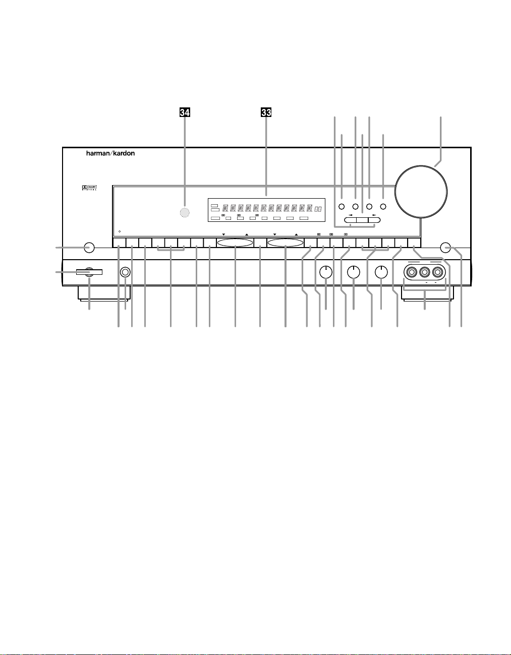
1 Main Power Switch
2 System Power Control
3 Power Indicator
4 Headphone Jack
5 Bass Control
6 Treble Control
7 Balance Control
8 Video 3 Inputs
9 Tape Selector
) CD
! DVD Input
@ Video Input Selectors
# 6-Channel Direct Selector
$ AM/FM
% Tuning Button
^ Preset Scan
& Preset Stations Selector
* FM Mode
( Dolby Digital Selector
Ó Dolby Pro Logic Selector
Ô Dolby 3 Stereo Selector
Analog Surround Mode Selectors
Ò Test Tone
Ú Surround Off
Û Mute
Ù Volume Control
ı Delay
ˆ Digital Input Selector
˜ Set Button
¯ Channel Select
˘ Speaker Select Button
¸ Selector Buttons
33
Information Display
34
Remote Sensor Window
Page 8

Front Panel Controls
5
1 Main Power Switch: Press this
button to apply power to the AVR45.
When the switch is pressed in the
unit is placed in a Standby mode, as
indicated by the amber LED 3 surrounding the System Power control
2. This button MUST be pressed in
to operate the unit. To turn the unit
off and prevent the use of the remote
control, this switch should be press
this switch until it pops out from the
front panel so that the word “OFF”
may be read at the top of the switch.
NOTE: In normal operation this
switch is left in the “ON” position.
2 System Power Control:When
the Main Power Switch1is “ON,”
press this button to turn on the
AVR45; press it again to turn the unit
off. Note that the Power Indicator
surrounding the switch 3will turn
green when the unit is on.
3 Power Indicator: This LED will
illuminate in amber when the unit is
in the Standby mode to signal that
the unit is ready to be turned on.
When the unit is in operation, the
indicator will turn green.
4 Headphone Jack: This jack may
be used to listen to the AVR45’s output through a pair of headphones.
Be certain that the headphones
have a standard 1⁄4" stereo phone
plug.
5 Bass Control: Turn this control to
modify the low-frequency output of
the left/right channels by as much as
±10dB. Set this control to a suitable
position for your taste and room
acoustics.
6 Treble Control:Turn this control
to modify the high-frequency output
of the left/right channels by as much
as ±10dB. Set this control to a
suitable position for your taste and
room acoustics.
7 Balance Control: Turn this
control to change the relative volume
for the front left/right channels.
NOTE: For proper operation of the
surround modes this control should
be at the midpoint, or “12 o’clock”
position.
8 Video 3 Inputs: These
audio/video inputs may be used for
temporary connectiion of video
games, camcorders, digital still
cameras or portable audio products.
To select a source connected to
these jacks, press the Vid 3 Input
Selector @.
9 Tape Selector: Press this button
to select the device connected to
the Tape Monitorjacks c as the
listening source. The previously
selected source will continue to
show in the Information Display
33
, and the red LED above the
button will illuminate to remind you
that you are listening to the tape
monitor output.
) CD: Press this button to select
the device connected to the CD
Input jacks § as the listening
source.
! DVD Input: Press this button to
select the device connected to the
DVD Play jacks ¶ as the listening
and viewing source.
@ Video Input Selectors: Press
one of these buttons to select a
source connected to the rear panel
Audio/Video inputs £fl, or the
front panel Audio/Video input 8.
# 6-Channel Direct Selector:
Press this button to select the output
of an optional, external 6-channel
decoder connected to the 6 Ch
Direct inputs ∞ as the listening
source.
$ AM/FM: Press this button to
select the tuner as the AVR45’s input
source. When it is first pressed the
last station tuned will be heard.
Press it again to change between
AM and FM bands.
% Tuning Button: Press the left
side of the button to tune lower
frequency stations and the right side
of the button to tune higher frequency
stations. When a station with a strong
signal is tuned, the TUNED indicator
R will illuminate in the Information
Display 33. A brief (1/2 second)
press of the button will manually
tune to the next frequency increment, while pressing and holding
the button for a longer period will
automatically tune to the next station
with a signal strong enough for
acceptable reception.
^ Preset Scan: Press this button
to automatically scan through the
stations that have been programmed
in the AVR45’s memory. The tuner
will play five seconds of each station
before moving to the next preset
station. To stop the scan when the
desired station is heard, press the
button again. (See page 26 for more
information on the tuner memory
system.)
Page 9

Front Panel Controls
6
& Preset Stations Selector: Press
this button to select stations that
have been entered into the preset
memory. (See page 26 for more
information on tuner programming.)
* FM Mode: Press this button to
select the stereo or mono mode for
FM tuning. In the STEREO mode a
Stereo indicator P will illuminate in
the information display , and stereo
reception will be provided when stations are transmitting stereo signals.
In the MONO mode the left and right
signals from stereo broadcasts will
be mixed together and reproduced
through all channels. Select MONO
for better reception of weak signals.
( Dolby Digital Selector: Press
this button to select the Dolby Digital
surround mode when listening to a
program that carries the Dolby
Digital information. (See pages
22–25 for more information on
surround modes and digital audio.)
Ó Dolby Pro Logic Selector: Press
this button to select the Dolby Pro
Logic surround mode when listening
to an analog program that is encoded
with surround-sound information. (See
pages 22–25 for more information on
surround modes.)
Ô Dolby 3 Stereo Selector: Press
this button to select the Dolby 3
Stereo listening mode. This mode is
used primarily when a program has
surround information when a center
channel speaker, but no surround
speakers, is installed. (See pages
22–25 for more information on
surround modes.)
Analog Surround Mode
Selectors: Press one of these
buttons to select the analog surround modes. These modes may
be used with any analog program
source to create a pleasing surround
effect. (See pages 22–25 for more
information on surround modes.)
Ò Test T one: Press this button to
begin the sequence of steps used to
set the AVR45’s output levels. When
this button is pressed, a test tone will
replace the currently selected listening source. (See page 19 for more
information on using the test tone to
set the output levels.)
Ú Surround Off: Press this button
to turn off all surround processing,
and to listen to a program in traditional stereo from the left front and
right front speakers only.
Û Mute: Press this button to
momentarily silence the speaker
output of the AVR45.
Ù Volume Control: Turn the knob
clockwise to increase volume,
counterclockwise to decrease the
volume.
ı Delay: Press this button to begin
the sequence of steps required to
enter delay time settings. (See page
20 for more information on delay
times.)
ˆ Digital Input Selector: When
playing a source that has a digital
output, press this button to select
between the Optical · and Coaxial
° Digital inputs. (See pages 22–25
for more information on digital audio.)
˜ Set Button: When making
choices during the setup and configuration process, press this button
to enter the desired setting, as
shown in the Information Display
33
, into the AVR45’s memory. (See
pages 17–24 for more information on
setup and configuration.)
¯ Channel Select: Press this
button to begin the process of
selecting and configuring the
AVR45’s output channels. (See
pages 17–24 for more information on
setup and configuration.)
˘ Speaker Select Button: Press
this button to begin the process of
selecting the speaker positions that
are used in your listening room. (See
pages 17–24 for more information on
setup and configuration.)
¸ Selector Buttons: When you are
establishing the AVR45’s configuration settings, use these buttons to
select between the choices available, as shown in the Information
Display 33.
33
Information Display: This
display delivers messages and
status indications to help you
operate the receiver. (See page 7
for a complete explanation of the
Information Display.)
34
Remote Sensor Window: The
sensor behind this window receives
infrared signals from the remote control. Aim the remote at this area and
do not block or cover it unless an
external remote sensor is installed.
Page 10
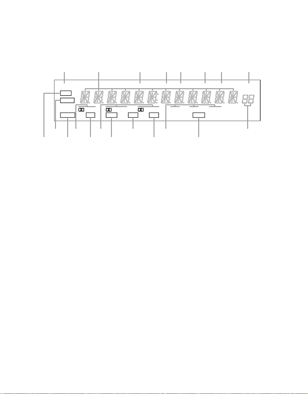
Front Panel Information Display
TUNED
SLEEP MONO STEREO AUTO MEMORY PRESET
MUTE
BYPASS
ANALOG
DIGITAL
OPT COAX
PRO LOGIC
AC-3 PCM NIGHT
THEATERHALL 2HALL 13
-
STEREO
A
B
CEG
L
K
J
TRQPONMS
DF H
I
7
A Mute
B Bypass
C Analog
D Dolby Digital Indicator
E Optical Source
F Analog Dolby Surround Mode Indicators
G Coax Source
H AC-3 Indicator
I PCM Indicator
J Analog Surround Mode Indicators
K Night Indicator
L Preset Number
M Preset Indicator
N Memory
O Auto
P Stereo Indicator
Q Mono Indicator
R Tuned Indicator
S Main Information Display
T Sleep Indicator
Page 11

Front Panel Information Display
8
A Mute: This indicator illuminates
to remind you that the AVR45’s output has been silenced by pressing
the Mute button Ûd. Press the
Mute button again to return to the
previously selected output level.
B Bypass: This indicator illumi-
nates when the surround processing
has been disabled by pressing the
Surround Off button Ú. When this
indicator is lit, the A VR45 will play traditional stereo sound using the front
left and front right speakers only.
C Analog: This indicator illuminates
when an analog input source is in use.
D Dolby Digital Indicator: This
indicator illuminates when a Dolby
Digital source is being played.
E Optical Source: This indicator
illuminates when a digital source
is in use via a connection to the
Optical Digital input ·.
F Analog Dolby Surround Mode
Indicators: These indicators illumi-
nate when one of the analog (matrix)
Dolby Surround modes is in use.
G Coax Source: This indicator illu-
minates when a digital source is in
use via a connection to the Coaxial
Digital input °.
H AC-3* Indicator: This indicator
illuminates when the AVR45 is
decoding a Dolby Digital input
source.
I PCM Indicator: This indicator
illuminates to show that a standard
PCM (SP/DIF) digital audio signal
is being decoded by the digital-toanalog converter.
J Analog Surround Mode
Indicators: These indicators illumi-
nate when one of the DSP generated
analog surround modes is in use
with an analog input source.
K Night Indicator: This indicator
lights when the AVR45 is in the Night
mode, which prevents the AVR45
from loud playback when digital
sources are in use.
L Preset Number: This two-digit
display indicates the station preset
number that is currently in use, or
that is being entered.
M Preset Indicator: This indicator
illuminates when one of the stations
entered into the preset memory is
tuned. The number that appears
below the indicator is the preset
station’s memory.
N Memory: This indicator flashes
when entering presets and other
information into the tuner’s memory.
O Auto: This indicator illuminates
when the “Auto” mode is in use for
FM tuning.
P Stereo Indicator: This indicator
illuminates when an FM station is
being tuned in stereo.
Q Mono Indicator: This indicator
illuminates when the tuner has been
placed in the monaural mode by
pressing the FM Mode button *.
Set the tuner for mono listening to
cut noise and improve the quality of
distant stereo signals.
R Tuned Indicator: This indicator
illuminates when a station is being
received with sufficient signal
strength to allow for acceptable
listening quality.
S Main Information Display: This
display shows messages relating to
the status, input source, surround
mode, tuner, volume level or other
aspects of unit’s operation.
T Sleep Indicator: This indicator is
illuminated when the Sleep function
is in use. The number that appears
above the indicator is the number of
minutes remaining before the AVR45
will return to the Standby mode.
Page 12
Rear Panel Connections
UNSWITCHED
TOTAL 100W MAX.
SWITCHED
TOTAL 50W MAX.
(120V.60Hz)
TOTAL 150W MAX
MODEL NO. AVR-45
HARMAN KARDON
NORTHRIDGE
CALIFORNIA, USA
MADE IN CHINA
FM
(75Ω)
AM
ANTENNA
GND
AC 120V 60 Hz
IN
OUT
TAPE
MONITOR
RIGHT
SPEAKERS 8 Ohms SPEAKER 8 Ohm
LEFT CENTER
VIDEO
2
PLAY
IN
REC
OUT
VIDEO
1
DVD
CD
SL
FLCENTER
SR FRSUB WOOFER
6 CH. DIRECT
FRONT
CENTER
SERIAL NO.
AC OUTLETS
RIGHT
SPEAKERS 8 Ohms
LEFT
SURROUND
AVIS: RISQUE DE CHOC
ELECTRIQUE - NE PAS OUVRIR
CAUTION
RISK OF ELECTRIC SHOCK
DO NOT OPEN
OUT
IN
TV
MONITOR
OUT
VIDEO 2
IN
OUT
DVD
VIDEO 1
SURR.
FRONT
OPTICAL
COAXIAL
CENTER SUB WOOFER
DIGITAL INPUT
PRE OUT
VIDEO
REMOTE CONTROL
·abcdflfl‡°¢¶£fi
›
‹
¤
⁄
‚
ª
•
¶
§
∞
¢
£
™
¡
9
l
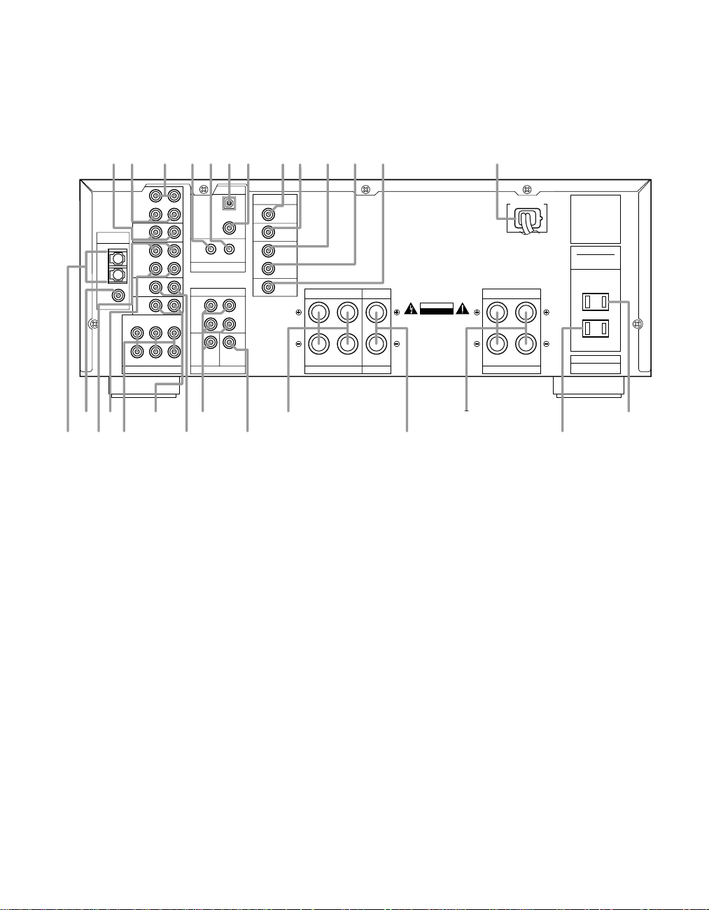
¡ AM Antenna
™ FM Antenna
£ Video 1 Inputs
¢ Video 1 Outputs
∞ 6-Channel Direct Inputs
§ CD Inputs
¶ DVD Inputs
• Pre-Outs
¡ AM Antenna: Connect the AM
loop antenna supplied with the
receiver to these terminals. If an
external AM antenna is used, make
connections to the AM and GND
terminals in accordance with the
instructions supplied with the
antenna.
™ FM Antenna: Connect an indoor
or external FM antenna to this
terminal.
ª Subwoofer Pre-Out
‚ Front
⁄ Center
l
Surround
‹ Unswitched AC Outlet
› Switched AC Outlet
fi Power Cable
‡ TV Monitor Video Output
° AC-3/PCM Coaxial Input
· AC-3/PCM Optical Input
a Remote IR In
b Remote IR Out
c Tape Monitor In
d Tape Monitor Out
fl Video 2 Inputs
£ Video 1 Inputs: Connect these
jacks to the audio and video
PLAY/OUT jacks of a VCR.
¢ Video Outputs 1: Connect these
jacks to the audio and video
RECORD/IN jacks of a VCR.
∞ 6-Channel Direct Inputs: If an
external digital audio decoder is
used for 5.1 (Dolby AC-3) audio,
connect the outputs of that decoder
to these terminals.
§ CD Inputs: Connect these jacks
to the output of a compact disc
player or CD changer.
¶ DVD Inputs: Connect the analog
audio outputs and composite video
output of a DVD or LV player to these
jacks.
• Pre-Outs: If external power
amplifiers are used for any channels,
connect them to these jacks.
Page 13

Rear Panel Connections
10
ª Subwoofer Pre-Out: Connect
this jack to the line level input of a
powered subwoofer. If an external
subwoofer amplifier is used, connect
this jack to the subwoofer amplifier
input.
‚ Front: Connect these terminals to
the front left/right speakers.
⁄ Center: Connect these terminals
to the center speaker.
l
Surround: Connect these terminals
to the surround speakers.
‹ Unswitched AC Outlet: This
outlet may be used to power any AC
device. The power will remain on at
this outlet regardless of whether the
AVR45 is on or off.
NOTE: The power consumption of
the device plugged into each of
these outlets should not exceed
100 watts.
› Switched AC Outlet: This outlet
may be used to power any device
that you wish to have turn on when
the unit is turned on with the System
Power Control switch 2.
fi Power Cable: Connect the AC
plug to a non-switched AC wall
output
fl Video 2 Inputs: Connect these
jacks to the audio and video outputs
of a TV Tuner, Cable TV converter
box, satellite receiver or any other
audio/video source.
‡ TV Monitor Video Output:
Connect this jack to the standard
(composite) video input of a TV
monitor or video projector to view
the on-screen menus and the
output of any standard video source
selected by the receiver’s video
switcher.
° AC-3/PCM Coaxial Input:
Connect the coax digital output from
a DVD player, HDTV receiver, LV
player or CD player to this jack. The
signal may be either a Dolby Digital
(AC-3) signal or a standard PCM
digital source.
· AC-3/PCM Optical Input:
Connect the optical digital output
from a DVD player, HDTV receiver,
LV player or CD player to this jack.
The signal may be either a Dolby
Digital (AC-3) signal or a standard
PCM digital source.
a Remote IR In: If the AVR45’s front
panel IR sensor is blocked due to
cabinet doors or other obstructions,
an external IR sensor may be used.
Connect the output of the sensor to
this jack.
b Remote IR Out: This connection
permits the IR sensor in the receiver
to serve other remote controlled
devices. Connect this jack to the “IR
IN” jack on Harman Kardon or other
compatible equipment.
c Tape Monitor In: Connect these
jacks to the PLAY/OUT jacks of an
audio recorder.
d Tape Monitor Out: Connect these
jacks to the RECORD/INPUT jacks of
an audio recorder.
Page 14
a
y
v
t
r
d
f
i
k
m
o
b
c
e
g
j
h
l
n
p
q
s
u
x
w
z
`
Remote Control Functions
11
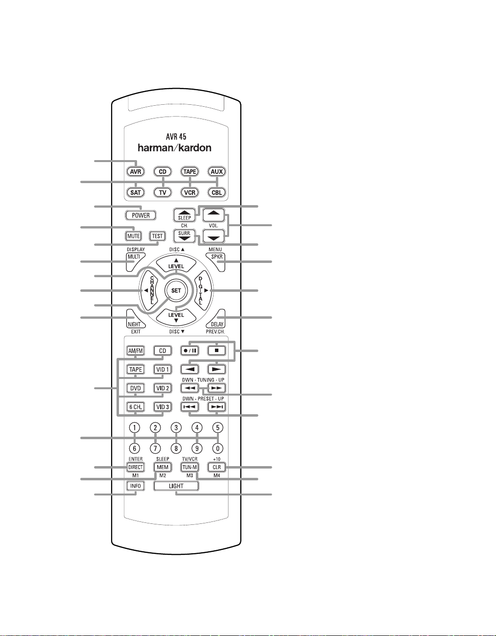
a AVR Selector
b Device Control Selectors
c Power Button
d Mute
e Test
f Display/Multiroom
⁄/¤
Buttons
g
‹
/Channel Button
h
i Set Button
j Night Mode
k Source Selectors
l Numeric Keys
m Direct/Enter
n Memory Button
o Info Button
p Light Button
q Tuner Mode
r Clear Button
s Preset Up/Down
t Tuning Up/Down
u Transport Controls
v Delay/Prev Ch.
›
/Digital Button
w
x Speaker Configuration
y Surround Mode Selector
z Volume
` Sleep Button
Page 15

Remote Control Functions
12
IMPORTANT NOTE: The AVR45’s
remote may be programmed to control up to eight devices, including
the AVR45. Before using the remote,
it is important to remember to press
the Device Control Selector button
abthat corresponds to the unit
you wish to operate. In addition, the
AVR45’s remote is shipped from
the factory to operate the AVR45
and Harman Kardon CD players
and cassette decks. The remote is
also capable of operating a wide
variety of other products using the
control codes that are part of the
remote. Before using the remote with
other products, follow the instructions on pages 28–29 to program the
proper codes for the products in
your system.
It is also important to remember that
many of the buttons on the remote
take on different functions, depending on the product selected using
the Device Control Selectors. The
descriptions shown here primarily
detail the functions of the remote
when it is used to operate the
AVR45. (See pages 28–31 for information about alternate functions for
the remote’s buttons.)
a AVR Selector: Press this button
to use the remote control for operation
of the AVR45. Note that the button will
briefly turn red after it has been
pressed to confirm your selection.
b Device Control Selectors:
Press one of these buttons to use
the remote to control the functions
of another audio/video device. Note
that the button will briefly turn red
after it has been pressed to confirm
your selection. (See pages 28–29 for
information on programming the
AVR45’s remote to operate these
devices.)
c Power Button: Press this button
to turn the currently selected device
on or off.
d Mute: Press this button to
momentarily silence the AVR45 or TV
set being controlled, depending on
which device has been selected.
When the AVR45 r emote is being pr ogrammed to operate another device,
this button is pressed with the Device
Control Selector button b to
begin the programming process.
(See page 28 for more information
on programming the remote.)
e Test: Press this button to begin
the sequence used to calibrate the
AVR45’s output levels. (See page 19
for more information on calibrating
the AVR45.)
f Display/Multiroom Button:
This button does not function with
the AVR45, but it is available for use
with other devices.
¤
g⁄/
purpose buttons. They will be used
most frequently to select a surround
mode. To change the surround mode,
first press the SURR/CH¤button
y. Next press these buttons to
scroll up or down through the list of
surround modes that appear in the
Information Display 33. (See page
24 for more information.) These
buttons are also used to increase
or decrease output levels used to
lower the AVR45’s output levels when
configuring the unit with either the
internal test tone or and external
source. (See pages 19 and 26 for
more information.) They are also used
to enter delay time settings after the
Delay button v has been pressed.
(See page 20 for more information.)
h
button is used to start the process of
setting the AVR45’s output levels to an
external source. Once this button is
pressed, use the ⁄/¤buttons g to
select the channel being adjusted,
then press the Set button i, followed by the ⁄/¤buttons again to
change the level letting. (See page 27
for more information.)
Buttons: These are multi-
‹
/Channel Button: This
i Set Button: This button is used
to enter settings into the AVR45’s
memory. It is also used in the setup
procedures for delay time, speaker
configuration and channel output
level adjustment. (See pages 17–21
for complete information.)
j Night Mode: Press this button
to activate the “Night” mode, preventing loud playback when the
digital modes are in use without
altering the dynamic range of the
output signal.
When the AVR45 r emote is being pr ogrammed to operate other devices,
this button is pressed to begin a
readout of a programmed code. (See
page 28 for more information.)
k Source Selectors: Press these
buttons to select an input source for
the AVR45. The AM/FMbutton is also
used to switch between frequency
bands when the tuner is in use.
NOTE: Pressing one of these buttons
selects the source only. In order to
control the actual source machine
using the remote you must press the
Device Control Selector button b
for the desired product.
l Numeric Keys: These buttons
serve as a ten-button numeric keypad to enter tuner preset positions.
They are also to be used to select
channel numbers when TV has been
selected on the remote, or to select
track numbers on a CD, DVD or LD
player, depending on how the
remote has been programmed.
NOTE: The 0 button has a dual func-
tion. It also serves as the CLEAR
button for use in programming the
tuner or clearing the system memory.
m Direct/Enter: Press this button
to select a radio station by entering
its frequency using the Numeric
Keys l. (See page 26 for more
information.)
Page 16

Remote Control Functions
90
min80min70min60min50min40min
30
min20min10min5min1min
OFF
13
n Memory Button: Press this
button to enter a radio station into
the AVR45’s preset memory. After
pressing the button the MEMORY
indicator N will flash, and you then
have five seconds to enter a present
memory location using the Numeric
Keys l. (See page 26 for more
information.)
NOTE: Although the word “Sleep”
appears above this button, it refers
to control of devices other than the
AVR45. Use the Sleepbutton ` to
control the A VR45’s Sleep function.
o Info Button: This button does
not function with the A VR45, but it is
available for use with other devices.
p Light Button: Press this button
to activate the remote’s built-in backlight for better legibility of the buttons
in a darkened room.
q Tuner Mode:Press this button
when the tuner is in use to select
between automatic tuning and
manual tuning. When the button is
pressed so that the AUTO indicator
O goes out, pressing the Tuning
buttons t will move the frequency
up or down in single-step increments. When the FM band is in
use, pressing this button when a
station’s signal is weak will change
to monaural reception, as indicated
by the MONO indicator Q. (See page
26 for more information.)
r Clear Button: This button does
not function with the A VR45, but it is
available for use with other devices.
s Preset Up/Down: When the
tuner is in use, these buttons scroll
through the stations that have been
programmed into the AVR45’s memory. When many source devices,
such as CD players, VCRs and cassette decks, are selected using the
Device Control Selectors b,
these buttons will normally function
as chapter step or track advance.
t Tuning Up/Down:When the
tuner is in use, these buttons will
tune up or down through the selected frequency band. If the Tuner
Mode button q has been pressed
so that the AUTO indicator O is illuminated, pressing these buttons will
cause the tuner to seek the next station with acceptable signal strength
for quality reception. When the AUTO
indicator O is NOT illuminated,
pressing these buttons will tune stations in single-step increments. (See
page 26 for more information.)
u Transport Controls: These controls do not control any functions of
the AVR45, but they are used extensively when operating a wide variety
of CD players, cassette decks and
VCRs. (See page 28 for information
on programming the remote to utilize
these buttons.)
v Delay/Prev Ch.: Press this button to begin the process for setting
the delay times used by the AVR45
when processing surround sound.
After pressing this button the delay
times are entered by pressing the
Set button i, and then using the
⁄/¤
buttons g to change the setting. Press the Set button again to
complete the process. (See page 20
for more information.)
›
w
/Digital Button: This button is
used to select the type of digital input
used with any one of the input sources
connected to the AVR45. After pressing this button, use the ⁄/¤buttons
g to make your selection between
OPTICAL E or COAXIAL G digital.
Press the Set button i to enter
your choice. (See page 24 for more
information.)
x Speaker Configuration: Press
this button to begin the process of
configuring the AVR45’s Bass
Management System for use with
the type of speakers used in your
system. Once the button has been
pressed, use the ⁄/¤buttons g to
select the channel you wish to set up.
Press the Set button i, and then
select another channel to configure.
When all adjustments have been
completed, press the Set button
twice to exit the settings and return
to normal operation. (See page 17
for more information.)
y Surround Mode Selector: Press
this button to begin the process of
changing the surround mode. After
the button has been pressed, use
the ⁄/¤buttons g to select the
desired surround mode. (See page
24 for more information.) Note that this
button is also used to tune channels
when the TV is selected using the
Device Control Selector b.
When the AVR45 r emote is being pr ogrammed for the codes of another
device, this button is also used in the
“Auto Search” process. (See page 28
for more information on programming
the AVR45 r emote.)
z Volume: Press these buttons to
raise or lower the system volume.
` Sleep Button: Press this button
to place the unit in the Sleep mode.
After the time shown in the display,
the AVR45 will automatically go into
the Standby mode. Each press of
the button changes the time until
turn-off in the following order:
Note that this button is also used
to change channels on your TV
when the TV is selected using the
Device Control Selector b.
When the AVR45 r emote is being pr ogrammed for the codes of another
device, this button is also used in the
“Auto Search” process. (See page 28
for more information on programming
the AVR45 r emote.)
Page 17
Installation and Connections
14
System Installation
After unpacking the unit, and placing it
on a solid surface capable of supporting
its weight, you will need to make the
connections to your audio and video
equipment. These steps need to be done
only when the receiver is first installed,
or when a change is made to the input
source equipment.
Audio Equipment Connections
We recommend that you use high-quality
interconnect cables when making connections to source equipment and recorders
to preserve the quality of the signals.
When making connections to audio
source equipment or speakers it is always
a good practice to unplug the unit from
the AC wall outlet. This prevents any possibility of accidentally sending audio or
transient signals to the speakers that may
damage them.
1. Connect the analog output of a CD
player to the CD inputs §.
NOTE: When the CD player has both
fixed and variable audio outputs it is best
to use the fixed output unless you find
that the input to the receiver is so low
that the sound is noisy, or high that the
signal is distorted.
2. Connect the Play/Out jacks of a cassette deck, MD or other audio recorder to
the Tape Monitor Injacks c. Connect
the Record/In jacks on the recorder to
the Tape Monitor Outjacks d on
the AVR45.
3. Connect the output of any digital
sources to be used to the appropriate
connections on the AVR45 rear panel.
Note that the Optical and Coaxial
digital inputs ·°may be used with
either a Dolby Digital (AC-3) source
or the output of a conventional CD or
LV player’s PCM (SP/DIF) output.
4. Assemble the AM Loop Antenna supplied with the unit as shown below.
Connect it to the AM and GNDscrew
terminals ¡.
5. Connect an FM antenna to the
FM (75 ohm) connection ™. The
FM antenna may be an external roof
antenna, an inside powered or wire lead
antenna or a connection from a cable
TV system. Note that if the antenna or
connection uses 300-ohm twin-lead
cable, you must use the 300-ohm-to75-ohm adapter supplied with the unit
to make the connection.
6. Connect the front, center and
surround speaker outputs ‚⁄
to the respective speakers.
To assure that all the audio signals are
carried to your speakers without loss of
clarity or resolution, we suggest that you
use high-quality speaker cable. Many
brands of cable are available, and the
choice of cable may be influenced by the
distance between your speakers and this
receiver, the type of speakers you use,
personal preferences and other factors.
l
Your dealer or installer is a valuable
resource to consult in selecting the
proper cable.
Regardless of the brand of cable selected,
we recommend that you use a cable constructed of fine, multistrand copper with a
gauge of 14 or smaller. Remember that in
specifying cable, the lower the number ,
the thicker the cable.
Cable with a gauge of 16 may be used for
short runs of less than ten feet. We do not
recommend that you use cables with an
AWG equivalent of 18 or higher due to
the power loss and degradation in
performance that will occur.
Cables that are run inside walls should
have the appropriate markings to indicate
listing with UL, CSA or other appropriate
testing agency standards. Questions about
running cables inside walls should be
referred to your installer or a licensed
electrical contractor who is familiar with
the NEC and/or the applicable local
building codes in your area.
When connecting wires to the speakers,
be certain to observe proper polarity.
Remember to connect the “negative” or
“black” wire to the same terminal on the
receiver and the speaker. Similarly, the
“positive” or “red” wire should be connected to the like terminal on the AVR45
and speaker.
We also recommend that the length of
cable used to connect speaker pairs be
identical. For example, use the same
length piece of cable to connect the front
left and front right or surround left and
surround right speakers, even if the
speakers are a different distance from
the AVR45.
Page 18

Installation and Connections
15
NOTE: While most speaker manufacturers
adhere to an industry convention of using
black terminals for negative and red ones
for positive, some manufacturers may
vary from this configuration. To assure
proper phase, and optimal performance,
consult the identification plate on your
speaker , or the speaker’s manual to verify
polarity . If you do not know the polarity
of your speaker , ask your dealer for
advice before proceeding, or consult
the speaker’s manufacturer.
7. Connections to a subwoofer are made
via a line level audio connection from
the Subwoofer Output ª to the line
level input of a subwoofer with a built-in
amplifier. If a passive subwoofer is used,
the connection first goes to a power
amplifier, which will be connected to one
or more subwoofer speakers.
Video Equipment Connections
Video equipment is connected in a fashion
similar to audio components. Again, the
use of high-quality interconnect cables is
recommended to preserve signal quality.
1. Connect a VCR’s audio and video
Play/Out jacks to the Video 1 In jacks
£ on the rear panel. The audio and
Record/Out jacks on the VCR should be
connected to the Video 1 Out jacks ¢
on the AVR45.
2. Connect the audio and video outputs
of a satellite receiver, cable TV converter
or television set or any other video source
to the Video 2 In jacks fl.
3. Connect the audio and video outputs
of a DVD or laser disc player to the DVD
jacks ¶.
4. Connect the TV Monitor Out ‡
jacks on the receiver to the video
input of your television monitor or
video projector.
System and Power Connections
The AVR45 is designed for flexible use
with external control components and
power amplifiers. These connections are
easy to make during an initial installation, or at a later date should you choose
to upgrade your system.
Remote Control Extension
If the receiver is placed behind a solid or
smoked glass cabinet door, the obstruction may prevent the remote sensor from
receiving commands. In this event, an
optional remote sensor may be used.
Connect the output of the remote sensor
to the Remote Cont. In jack a.
If other components are also prevented
from receiving remote commands, only
one sensor is needed. They may use this
unit’s sensor or a remote eye by running
a connection from the Remote Cont.
Out jack b to the Remote In jack on
Harman Kardon or other compatible
equipment.
External Audio Power Amplifier
Connections
If desired, optional external power audio
power amplifiers may be used with the
AVR45. Connections to these amplifiers
are made by using audio interconnect
cables connected to both the Preamp
Outputs • on the rear panel and
the audio input jacks of the external
amplifiers.
External Audio Decoder Connection
To provide for the ultimate flexibility,
the AVR45 may be used in conjunction
with optional, external decoders for
digital audio systems other than the
AVR45’s own built-in Dolby Digital
system. If an external decoder is used,
connect the output jacks of the decoder
to the 6-Channel Direct inputs ∞,
making sure to match channels.
These jacks may also be used for connections to devices usch as DVD players or
High Definition Television (HDTV) sets or
decoders that feature built-in digital surround decoders. Although the digital
decoding system in the AVR45 will typically
provide audio performance that is superior
to other decoders, you may use these jacks
to provide an additional 6-channel input
for connection to a DVD player or HDTV
set with a built-in decoder and discrete
6-channel analog outputs.
AC Power Connections
This unit is equipped with two accessory
AC outlets. They may be used to power
accessory devices, but they should not be
used with high-current draw equipment
such as power amplifiers. The total power
draw may not exceed 50W to each outlet.
The Switched › outlet will receive
power only when the unit is on. This is
recommended for devices that have no
power switch, or a mechanical power
switch that may be left in the “ON”
position.
NOTE: Devices with electronic power
switches may only go into a Standby
mode when plugged in here.
The Unswitched ‹ outlet will receive
power as long as the unit is plugged into
a powered AC outlet.
Finally, when all connections are complete, plug the power cord into a nonswitched120-volt AC wall outlet. You’re
almost ready to enjoy the AVR45!
Page 19
System Configuration
Right Front
Speaker
Left Front
Speaker
No more
than 24"
Center Front Speaker
Center Front
Speaker
Optional Rear Wall Mounting
TV or Projection Screen
Right Front
Speaker
Left Front
Speaker
No more than 6 feet
when rear-mounted
speakers are used
At least 2 feet
At least 6 inches from ceiling
16
When all audio, video and system connections have been made, there are a few
configuration adjustments to be made. A
few minutes spent to correctly configure
and calibrate the unit will greatly add to
your listening experience.
Speaker Selection and Placement
The placement of speakers in a multichannel-home-theater system can have
a noticeable impact on the quality of
sound reproduced.
No matter which type or brand of speakers
is used, the same model or brand of
speaker should be used for the front left,
center and right speakers. This creates a
seamless front soundstage, and eliminates the possibility of distracting sonic
disturbances that occur when a sound
moves across mismatched front channel
speakers.
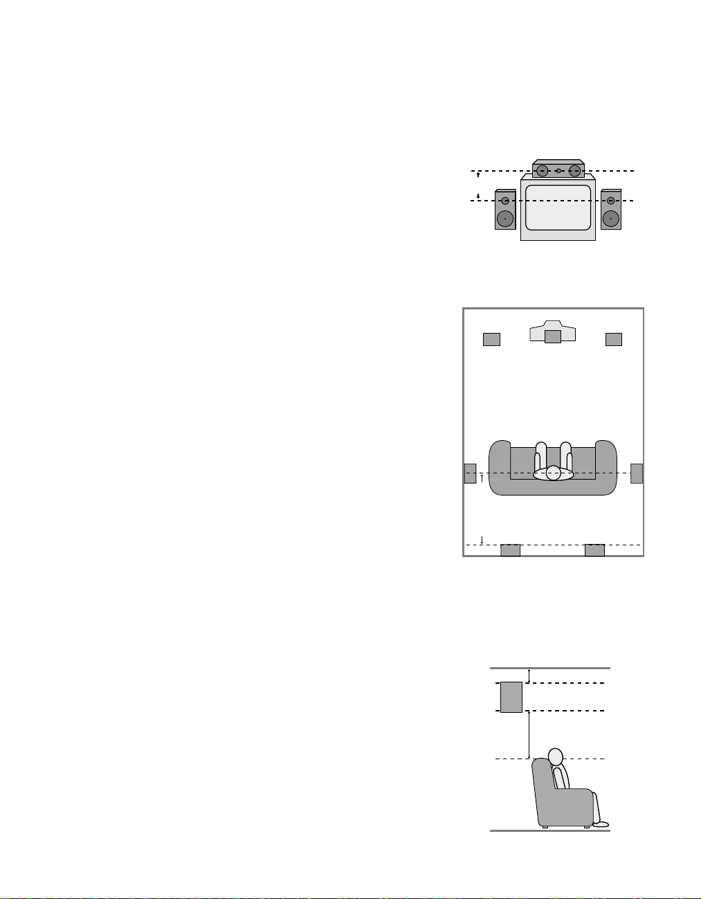
Speaker Placement
Depending on the type of center channel
speaker in use and your viewing device,
place the center speaker directly above or
below your TV or in the center behind a
perforated front projection screen.
Once the center channel speaker is
installed, position the left and right
front speakers so that they are as far
away from one another as the center
channel speaker is from the preferred
listening position. Ideally, the front
channel speakers should be placed so
that their tweeters are no more than 24"
off center from the tweeter in the center
channel speaker.
Depending on the specifics of your room
acoustics and the type of speakers in use,
you may find that imaging is improved
by moving the front left and right speakers slightly forward of the center channel
speaker. If possible, adjust all front
loudspeakers so that they are aimed at
ear height when you are seated in the
listening position.
Using these guidelines, you’ll find that it
takes some experimentation to find the
correct location for the front speakers in
your particular installation. Don’t be
afraid to move things around until the
system sounds correct. Optimize your
speakers so that pans across the front of
the room sound smooth, and that sounds
from all speakers appear to arrive at the
listening position at the same time without delay from the center speaker as
opposed to the left and right speakers.
Surround speakers should be placed on
the side walls of the room, at or slightly
behind the listening position. The center
of the speaker should face into the room.
The speakers should be located so that
the bottom of the cabinet is at least two
feet higher than the listeners’ ears when
seated in the desired area.
If side wall mounting is not practical, the
speakers may be placed on a rear wall,
behind the listening position. Again, they
should be located so that the bottom of
the cabinet is at least two feet higher
than the listeners’ ears. The speakers
should be no more than six feet behind
the rear of the seating area.
Subwoofers produce non-directional
sound, so they may be placed almost
anywhere in a room. Subwoofer placement is highly influenced by room size
and shape, and the type of subwoofer
used. Follow the instructions of the subwoofer’s manufacturer, or experiment
with the best location for a subwoofer in
your listening room.
A) Front Channel Speaker Installation
with Direct-View TV Sets or Rear-Screen
Projectors
B) The distance between the left and right
speakers should be equal to the distance
from the seating position to the viewing
screen.You may also experiment with
placing the left and right speakers slightly
forward of the center speaker.
Page 20

System Configuration
17
System Setup
Once the speakers have been placed in the
room and connected, the final step in the
setup process is to enter the settings that
configure the AVR45’s bass management
system for the type of speakers used in
your system, the calibration of the output
levels and the delay times used by the surround sound processor. Before proceeding
further, this is a good time to review the
installation section of the manual to
make certain that all connections are
properly made.
You are now ready to power up the AVR45
to begin these final adjustments.
1. Plug the Power Cablefl to an
unswitched AC outlet.
2. Press the Main Power Switch1
in so that it latches in with the “OFF”
wording on the top of the switch
inside the front panel. Note that the
Power Indicator3 will turn
amber, indicating that the unit is in
the Standby mode.
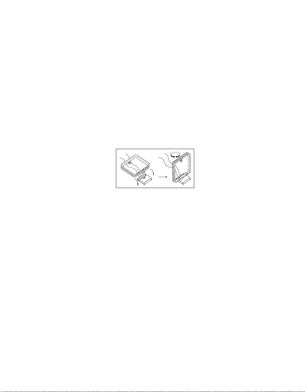
3. Install the four supplied AAA batteries
in the remote as shown. Be certain to
observe the (+) and (–) polarity
indicators shown in the bottom of the
battery compartment.
4. Turn the AVR45 on either by pressing
the System Power Control3 on
the front panel, or via the remote by
first pressing the AVR Selectora,
and then pressing the Powerbutton
c. The Power Indicator 3 will
turn green to confirm that the unit is
on, and the Information Display ˝
will also light up.
Speaker Configuration
The first few adjustments tell the AVR45,
which type of speakers are in use. This is
important as it adjusts the settings that
determine which speakers receive lowfrequency (bass) information. For each
of these settings use the LARGE setting if
the speakers for a particular position are
traditional full-range loudspeakers that
are capable of reproducing sounds
below 100Hz. Use the SMALL setting for
smaller, frequency-limited satellite
speakers that do not reproduce sounds
below 100Hz. Note that when “small”
speakers are used, a subwoofer is
required to reproduce low-frequency
sounds. Remember that the “large” and
“small” descriptions do not refer to the
actual physical size of the speakers, but
their ability to reproduce low-frequency
sounds. If you are in doubt as to which
category describes your speakers, consult
the specifications in the speakers’ owner’s
manual, or ask your dealer.
With the AVR45 turned on, follow these
steps to configure the speakers:
1. Put the AVR45 in the Dolby Pro Logic
mode by pressing the Dolby Pro
Logic Selector Ó on the front
panel or by pressing the Surround
Mode Selector yon the remote,
followed by the
⁄/¤
buttons g
until PRO LOGIC appears in the
Main Information Display S and
the PRO LOGIC indicator F lights.
2. Press the Speaker button x˘on
the remote or front panel. The words
FRNT SPEAKER will appear in the
Main Information DisplayS .
3. Press the Set button i˜.
4. Press the
⁄/¤
buttons g on the
remote or the Selector buttons¸
on the front panel until either
LARGE or SMALL appears to match
the type of speakers you have at the
left front and right front positions, as
described by the definitions shown
below.
When SMALL is selected, lowfrequency sounds will be sent to the
subwoofer output only. Note that if
you choose this option, and there is
no subwoofer connected, you will
not hear any low-frequency sounds
from the front channels.
Page 21

System Configuration
18
When LARGE is selected, a fullrange output will be sent to the
front left and right outputs, and
NO low-frequency signals will be
sent to the subwoofer output.
5. When you have completed your
selection for the front channel, press
the Set button i˜, and then
press the
⁄/¤
buttons g on the
remote or the Selector buttons¸
on the front panel to change the display to CEN SPEAKER.
6. Press the Set button i˜again,
and use the
⁄/¤
buttons g on
the remote, or the Selector buttons
¸ on the front panel, to select the
option that best describes your system
based on the speaker definitions
shown above.
When CEN SP SMALL is
selected, low-frequency center
channel sounds will be sent to the
subwoofer output only. Note that if
you choose this option and there is
no subwoofer connected, you will
not hear any low-frequency sounds
from the center channel speaker.
When CEN SP LARGE is
selected, a full-range output will be
sent to the center speaker output,
and NO center channel signal will
be sent to the subwoofer output.
When CEN SP NONE is selected,
no signals will be sent to the center
channel output. The receiver will
operate in a “phantom” center
channel mode and center channel
information will be sent to the left
and right front channel outputs.
7. When you have completed your
selection for the center channel, press
the Set button i˜, and then
⁄/¤
press the
buttons g on the
remote or the Selector buttons¸
on the front panel to change the
display to SUR SPEAKER.
8. Press the Set button i˜again,
and then use the
⁄/¤
buttons g
on the remote or the Selector
buttons¸ on the front panel to
select the option that best describes
your system based on the speaker
definitions shown above.
When SUR SP SMALL is
selected, low-frequency surround
channel sounds will be sent to the
subwoofer output only. Note that if
you choose this option and there is
no subwoofer connected, you will
not hear any low-frequency sounds
from the surround speaker.
When SUR SP LARGE is selected,
a full-range output will be sent to the
surround channel outputs, and NO
surround channel signals will be sent
to the subwoofer output.
When SUR SP NONE is selected,
surround sound information will be
split between the front left and front
right outputs. Note that for optimal
performance when no surround
speakers are in use, the Dolby 3
Stereo mode should be used instead
of Dolby Pro Logic.
9. When you have completed your
selection for the surround channel,
press the Set button i˜, and
then press the
⁄/¤
buttons g on
the remote or the Selector buttons¸
on the front panel to change the display
to SÐW SPEAKER.
10. Press the Set button i˜, and
then press the
⁄/¤
buttons g on
the remote or the Selector buttons¸
on the front panel to select the option
that best describes your system.
Select S-W SP ON if a subwoofer
is connected to your system.
Select S-W SP OFF if a subwoofer is
NOT connected to your system. Note
that when no subwoofer is selected,
low-frequency sounds below 100Hz
will be sent to the front left/right
speakers, provided that the selection
in step 4, above, has been set to
LARGE. Otherwise, no low-frequency
sounds will be heard. This option is
not available when the front, center or
surround speakers are set to SMALL.
Page 22

System Configuration
19
11. When all speaker selections have
been made, press the Set button i
˜ to return to normal operation.
Output Level Adjustment
Output level adjustment is a key part of
the configuration process for any surround sound product. It is particularly
important for a Dolby Digital receiver
such as the AVR45, as correct outputs will
ensure that you hear sound tracks in their
proper place with the proper intensity .
IMPORTANT NOTE: Many listeners
areoften confused about theoperation
ofthe surround channels.While some
assumethat sound shouldalways be
comingfrom each speaker, mostof the
timethere will belittle orno soundin
thesurround channels. Thisis because
theyare only usedwhen amovie director
orsound mixer specificallyplaces sound
thereto create ambiance, aneffect or to
continue action from the front of the
room to the rear. When theoutput levels
areproperly set it isnormal forrear/
surround speakers tooperate only
occasionally. Artificially increasingthe
volumeto the rearspeakers maydestroy
theillusion of anenveloping soundfield
thatduplicates the wayyou hearsound
ina movie theateror concerthall.
Before beginning the adjustment process
make certain that all speaker connections
have been properly made. The system
volume should be set to the level that
you will use during a typical listening
session. Finally, make certain that the
Balance Control7 is set to the center
“12 o’clock” position.
To adjust and calibrate the output levels,
follow these steps. For accurate calibration,
it is a good idea to make these adjustments
from the location in your room that is
your favorite listening position:
1. Put the AVR45 in the Dolby Pro Logic
mode by pressing the Dolby Pro
Logic Selector Ó on the front
panel or by pressing the Surround
Mode Selector yon the remote,
followed by the
⁄/¤
buttons g
until PRO LOGIC appears in the
Main Information Display S and
the PRO LOGIC indicator F lights.
2. Press the Test T onebutton eÒ
on the remote or front panel. The
words T-TFL 0dBwill appear
in the Main Information Display
S , and the letters FL will flash once
each second.
3. At this point, the test noise will begin
to circulate among all the speakers in
a clockwise rotation.
NOTE: This is a good time to verify
that the speakers have been properly
connected. As the test noise circulates,
listen to make certain that the sound
comes from the speaker position
shown in the Main Information
Display. If the sound from a speaker
location does NOT match the position
indicated in the display, turn the
AVR45 off and check the speaker
wiring to make certain that each
speaker is connected to the correct
output terminal.
4. After checking for speaker placement,
let the test noise circulate again, and
listen to see which channels sound
louder than the others. Using the
front left (FL in the display) speaker
as a reference, press the
g on the remote or the Selector
⁄/¤
buttons
buttons¸ on the front panel on
each channel to begin to bring them
to the same level. Note that when one
of the buttons is pushed, the test noise
circulation will pause on the channel
being adjusted to give you time to
make the adjustment. When you
release the button, the circulation
will resume.
5. Continue to adjust the individual
speakers until they all have the same
volume. Note that adjustments
should be made with the
⁄/¤
buttons g on the remote or the
Selector buttons¸ on the front
panel only, NOT the main volume
controls. Then press the Set button
i˜to memorize the change. If
you are using a sound pressure (SPL)
meter for precise level adjustment, set
the volume so that the meter reads
75dB, C-Weighting Slow.
NOTE: The subwoofer output level is not
adjustable using the test tone. To change
the subwoofer level, follow the steps for
Output Level Trim Adjustment on page
27.
6. When you have adjusted the outputs
so that all channels have the same
level, press the Test T onebutton
eÒon the remote or front panel
to complete the adjustment.
Page 23

System Configuration
20
Delay Settings
One aspectof the surroundmodes is the
delay ofaudio signals betweenthe front
speakers andthe rear speakers.Each
surround modeis factory presetwith a
specific delaytime, but itis possible to
individually adjustthe delay timingto
custom tailorthe sound toyour individual tasteand the acousticconditions in
your listeningroom or hometheater.
The factorysetting is appropriatefor
most rooms,but some installations
create anuncommon distance between
the frontand surround speakersthat may
cause thearrival of frontchannel sounds
to becomedisconnected from surround
channel sounds.
Toresynchronize thefront and surround
channels, followthese steps:
1. Measure thedistance from the
listening/viewing positionto the
front speakers.
2. Measure thedistance from the
listening/viewing positionto the
surround speakers.
3. Subtract thedistance to thesurround
speakers fromthe distance tothe
front speakers.
a. When setting the delay time for the
Dolby Digital surround mode, the
optimal delay time is the resulting
figure. For example, if the front
speakers are ten feet away and the
surround speakers are five feet
away, the optimal delay time is
figured as 10–5=5. Thus, in this
example, the delay should be set at
five milliseconds.
b. When setting the delay time for
the Pro Logic mode, take the result
of the subtraction and add 15 to
obtain the optimal delay time. For
example, if the front speakers are
ten feet away and the surround
speakers are five feet away, the
optimal delay time is figured
as 10–5+15=20. Thus, in this
example, the delay should be set
at twenty milliseconds.
The Dolby Digital mode also provides a
separate setting for the center channel
delay mode, since the discrete nature
of Dolby Digital signals makes the
location of the center channel speaker
more critical. To calculate the delay for
the center channel, measure the distance
from the preferred listening position in
the center of the room to both the center
channel speaker and either the left or
right speaker.
NOTE: The Theater, Hall 1 and Hall 2
modes use a fixed, non-adjustable
delay time.
If the distances are equal no further
adjustment is required and the center
delay should be set to zero. If the distance
to the front speakers is greater than the
distance to the center speaker you may
wish to reposition the speakers by moving
the front left/right speakers closer to the
listening position or the center speaker
further away from the listening position.
If repositioning of the speakers is not
possible, adjust the center delay time so
that you add one millisecond of center
channel delay for each foot that the
distance to the center speaker lags
behind the front speakers. For example,
if the front left/right speakers are each
10 feet from the listening position and
the center channel speaker is 8 feet
away, the delay is figured as 10–8=2,
suggesting an optimal center delay of
2 milliseconds.
To set the delay times, follow these steps:
1. Put the AVR45 in the Dolby Pro Logic
mode by pressing the Dolby Pro
Logic Selector Ó on the front
panel, or by pressing the Surround
Mode Selector yon the remote,
followed by the
⁄/¤
buttons g
until PRO LOGIC appears in the
Main Information Display S and
the PRO LOGIC indicator F lights.
2. Press the Delay button vı on
the remote or front panel. The words
S DELAY TIME will appear in the
Main Information DisplayS .
Page 24

System Configuration
21
3. Press the Set button i˜.
4. Adjust the delay time by pressing the
⁄/¤
buttons g on the remote or
the Selector buttons¸ on the front
panel until the delay time figure calculated using the formula entered
above appears in the display.
5. If no adjustment is needed for
the center channel delay, press the
Set button i˜to enter the
setting into the AVR45’s memory.
If the calculations outlined above
for the center channel delay require
an adjustment, proceed with the
following steps:
6. Select a digital input by pressing
the Digital button wˆ. Press
⁄/¤
the
buttons g on the remote
or the Selector buttons¸ on the
front panel until either COAX or
DIGITAL appear in the Main
Information Display S . Note that
for this adjustment, either input may
be selected.
7. Press the Set button i˜.
8. Select the Dolby Digital mode either
by pressing the front panel Dolby
Digital Selector( or by pressing
the Surround Mode Selector y
on the remote, and then pressing the
⁄/¤
buttons g on the remote
until DOLBY AC-3 appears in the
Main Information Display S .
Ignore any “NO DATA” message
that may appear.
9. Press the Delay button vı on
the remote or front panel. The words
S DELAY TIME appears in the
Main Information Display S .
10. Press the
⁄/¤
buttons g on the
remote once, so that C DELAY
TIME appears in the Main
Information Display S .
11. Press the Set button i˜.
12. Press the
⁄/¤
buttons g on
the remote until the desired delay
time for the center channel appears
in the display.
13. Press the Set button i˜to enter
the setting into the AVR45’s memory.
Congratulations! You have now completed
the setup, adjustment and calibration of
the A VR45. You are now ready to enjoy the
finest in music and home theater listening.
Page 25

Operation
90
min80min70min60min50min40min
30
min20min10min5min1min
OFF
22
Basic Operation
Once you have completed the setup and
configuration of your new receiver, it is
simple to operate and enjoy. The following instructions will provide the steps
needed to enjoy the AVR45:
• When using the AVR45 for the first
time, it is necessary to press the Main
Powerbutton
turn the unit on. This places the unit in a
standby mode, as indicated by the amber
color of the Power Indicator3. Once
the unit is in standby, you may begin a
listening session by pressing the System
Power Control
the Powerbutton con the remote.
Note that the Power Indicator3will
turn green. This will turn the unit on and
return it to the input source that was last
used. The unit may also be turned on
from standby by pressing any of the
Source Selectorbuttons on the remote
k
or front panel
To turn the unit off at the end of a listening session simply press the System
Power Control2 on the front panel
or the Power button con the remote.
Power to any equipment plugged into
the rear panel Switched AC Outlet
› will be shut off and the Power
Indicator 3 will turn amber.
When the remote is used to turn the unit
“off” it is actually placing the system in a
standby mode, as indicated by the amber
color of the Power Indicator3.
When you will be away from home for
an extended period of time it is always
a good idea to completely turn the
1
on the front panel to
2
on the front panel or
9)!@#$
unit off using the front panel Main
PowerSwitch
1
. Note that all preset
memories are lost if the unit is left
turned off with the Main Power
1
Switch
for more than two weeks.
Source Selection
• To select a source at any time, press
any of the Source Selector buttons on
the remote kor front panel
@#$
• The front panel Video 3 Inputs
may be used to connect a device such as
a video game or camcorder to your home
entertainment system on a temporary
basis.
• When an audio source is selected the
last video input used remains routed to
the Video Outputs 1 ¢ and TV
Monitor Output ‡. This permits
simultaneous viewing and listening to
different sources.
.
• During a listening session you may
wish to adjust the Bass 5and Treble
6
• Adjust the volume to a comfortable
level using the front panel Volume
Control Ù or remote Volume
Up/Down
• To temporarily silence all speaker
outputs press the Mute button
This will cut the output to all speakers,
but it will not effect any recording or
dubbing that may be in progress. When
the system is muted the MUTE indicator
A will light in the Information
Display
Û
.
controls to suit your listening tastes.
z
buttons.
˝
. Press the Mute button
again to return to normal operation.
9)!
8
dÛ
d
• For private listening, plug the 1/4"
stereo phone plug from a pair of stereo
headphones into the front panel
Headphone jack
4
.
• When a Video Input source is selected
the video signal for that input will be
routed to the TV Monitor Video Output
jack ‡ and will be viewable on a TV monitor connected to the A VR45. Make certain
that your TV is set to the proper input to
view the signal.
• To program the AVR45 for automatic
turn off, press the Sleep button`on
the remote. Each press of the button will
increase the time before shut down in the
following sequence:
The sleep time will be displayed in the
Information Display and it will count
down until the time has elapsed.
When the programmed time has elapsed
the unit will automatically turn off. Note
that the front panel display will dim to
one half brightness when the Sleep function is programmed. To cancel the Sleep
function, press the Sleep button
until the information display returns to
normal brightness and the Sleep
indicator numbers disappear.
.
Surround Mode Selection
One of the most important features of
the AVR45 is its ability to reproduce a full
multichannel surround sound field from
Dolby Digital sources, analog matrix
surround encoded programs and standard stereo programs. In all a total of
seven listening modes are available on
the AVR45.
`
Page 26

Operation
23
Selection of a surround mode is based on
personal taste, as well as the type of program source material being used. For
example, motion pictures or TV programs
bearing the logo of one of the major surround encoding processes, such as Dolby
Surround, DTS†Stereo or UltraStereo
††
may be played in either the Dolby Digital,
Dolby Pro Logic or Movie Surround
depending on the source material.
Surround Mode Chart
MODE
DOLBY DIGITAL
DOLBY PRO LOGIC
FEATURES
This mode is available only when the source material is encoded with Dolby Digital
(AC-3) data. It provides up to five separate main audio channels and a special dedicated Low-Frequency Effects channel.
Dolby Pro Logic is the standard mode for analog surround sound decoding. It uses
information encoded in a two-channel stereo recording to produce four distinct
channels: Left, Center, Right and Surround. Use this mode for accurate reproduction
of programs bearing the Dolby Surround, DTS Stereo, UltraStereo or other
“Surround” logos. Surround encoded programs include videocassette, DVD and LD
movies, TV and cable programs, radio programs and audio CDs. Dolby Pro Logic
processing may also be used to provide a pleasing surround effect with some
stereophonic source material that does not carry surround encoding.
NOTE: Once a program has been
encoded with surround information, it
retains the surround matrix as long as
the program is broadcast in stereo. Thus,
movies with surround sound will carry
surround information when they are
broadcast via conventional TV stations,
cable, pay TV and satellite transmission.
In addition, a growing number of madefor-television programs, sports broadcasts, radio dramas and music CDs are
also recorded in surround sound. You
may obtain a list of these programs and
discs from the Dolby Laboratories web
site at www.dolby.com
When a program is not listed as carrying
intentional surround information, you
may find that Pro Logic or Dolby 3-Stereo
modes often deliver enveloping surround
presentations through the use of the
natural information present in all stereo
recordings. However, for stereo, but nonsurround programs, we suggest that you
try the Hall 1, Hall 2 or Theater modes.
DELAY TIME RANGE
Center: 0 ms –5 ms
Surround: 0 ms –15 ms
15 ms – 30 ms
Initial Setting = 20 ms
DOLBY 3 STEREO
THEATER
HALL 1 and HALL 2
STEREO
Dolby 3 Stereo uses the information contained in a surround encoded or two-channel
stereo program to create center channel information. In addition, the information
that is normally sent to the rear channel surround speakers is carefully mixed in with
the front left and right channels for increased realism. Use this mode when you have a
center channel speaker, but no surround speakers.
Theater Surround processing uses matrix surround decoding to simulate a standard
movie or stage theater.
These modes are designed for use with stereo recordings. They provide a sound-field
effect that simulates the complex combination of direct and reflected sounds that
create the rich reverberant atmosphere of a medium-sized concert hall (Hall 1) or a
larger concert hall (Hall 2).
This mode turns off all surround processing and presents the pure left and right
channel presentation of two channel stereo programs.
No Surround Channels
27.3 ms
Hall 1 – 41.6 ms
Hall 2 – 67.4 ms
No Surround Channels
Page 27

Operation
24
Surround modes are selected using either
the front panel controls or the remote. To
select a surround mode from the front
panel, simply press the button that corresponds to the desired mode
. To select a surround mode using the
(ÓÔ
remote, press the Surround Mode
Selector y, and then press the ⁄/
¤
buttons g to change the mode. As
you press the buttons, the surround
mode name will appear in the Main
Information Display S, and an
individulal mode indicator will also
light up D /F /J.
Note that the Dolby Digital Mode may
only be selected when a Dolby Digital
source is playing. For more information
on Dolby Digital, see the following section
of this manual.
To listen to a program in traditional twochannel stereo, using the front left and
front right speakers only (plus the subwoofer if installed and configured), press
the Surround Off buttonÚ on the
front panel, or follow the insturctions
shown above for using the remote until
SURR OFF appears in the Main
Information Display S. When the
AVR45’s surround circuits are turned off,
and it is in the Stereo mode, the BYPASS
indicator B will illuminate in the
Information Display
˝
.
Digital Audio Playback
Dolby Digital
Dolby Digital (also known as AC-3) is the
latest advancement in surround-sound
technology, delivering up to five fullrange surround channels (left, center,
right, left surround and right surround)
plus a special dedicated Low-Frequency
Effects (LFE) channel. This represents a
major advancement over traditional
analog surround in that each surround
channel is fully discrete and capable of
full bandwidth reproduction. Dolby
Digital is available on DVD and LV discs,
and it will be a part of the new highdefinition television (HDTV) system
when digital broadcasting begins in
1998. Dolby Digital for the home is based
on the same system used to deliver digital
audio sound tracks in movie theaters,
enabling true cinema reproduction in
your home.
To utilize the Dolby Digital mode you
must have a digital source properly
connected to the AVR45. Connect the
Digital datastream outputs from DVD
players, HDTV receivers and CD players to
the AC-3/PCM Coaxial or Optical
inputs on the rear panel °·. In order
to provide a backup signal and a source
for recording, the analog outputs provided on digital source equipment should
also be connected to their appropriate
inputs on the AVR45 rear panel (e.g.,
connect the analog stereo audio output
from a DVD to the DVD inputs ¶ on
the rear panel when you connect the
digital outputs.)
When playing back a digital source, first
select the input using the remote or front
panel controls as outlined above. Next
select the digital source by pressing the
appropriate Digital Input button w
ˆ and then using the ⁄/
¤
buttons g
on the remote or the Selector buttons
¸ on the front panel to choose either
COAXIAL or DIGITAL, as it
appears in the Main Information
Display S. Press the Set button i
˜ to enter the desired choice. When
the digital source is playing, the AVR45
will automatically detect if it is a multichannel Dolby Digital source or a conventional PCM signal, which is the
standard output from CD players. An
indicator will light in the Information
Display to confirm the digital signal is
AC-3 H or PCM I and if the source is
OPTICAL E or COAX G.
When an AC-3 source is playing, the
AVR45 will automatically switch to the
Dolby Digital surround mode. It is important to note, however, that not all AC-3
sources are encoded with the full complement of five channels plus LFE. When a
digital source is playing, the Main
Information DisplayS will change to
show the input source and digital type
(OPTICAL or COAX). When a source with
Dolby Digital encoding is playing, the
input source name will appear in the
Information Display, followed by a
numeric key to the type and number
of channels being decoded as follows:
Page 28

Operation
25
3/2.1: This message appears
when a full complement of Dolby
Digital signals is present: 3 front
channels (left, center and right),
2 surround channels (surround
left and surround right) and “1”
channel, which is the dedicated Low
Frequency Effects (LFE) channel.
3/1: This message indicates the
AC-3 system is decoding a standard
Dolby Pro Logic signal with left,
center and right front channels and
a signal mono surround channel.
2/0: This message indicates that
the AC-3 system is decoding a traditional two-channel stereo signal and
that no center, surround or LFE
signals are present.
1+1: This is a monaural signal
that plays the same information in
both the left front and right front
speakers. There is no sound sent to
the center or surround speakers.
1/0: This is a monaural signal
that plays through the center channel
speaker only. There is no sound at the
front left/right or surround speakers.
Night Mode
A special feature of Dolby Digital is the
Night mode, which enables AC-3 input
sources to be played back with their full
range while reducing the minimum peak
level by 1/4 to 1/3. This prevents abruptly
loud transitions from causing disturbances without reducing the impact of
the digital source. The Night mode is
available only when AC-3 signals with
special data are being played.
To engage the Night mode, press the
Night buttonj on the remote and
note that the NIGHT indicator K will
illuminate in the Information Display.
IMPORTANT NOTES ON
DOLBY DIGITAL PLAYBACK:
1. When the digital playback unit is in a
pause, fast forward or chapter search
mode the digital audio data may
momentarily stop, causing a NO
DATA message to be displayed. This is
normal and does not indicate a problem
with either the AVR45 or the source
machine. The AVR45 will return to Dolby
Digital/AC-3 playback as soon as the data
is available when the machine is in a
standard play mode.
2. The AVR45 will decode digital audio
sources with a sampling frequency of
32kHz, 44.1kHz and 48kHz. Although
this will enable it to decode virtually all
DVD movies and HDTV sources, it is possible that some future digital sources
may not be compatible with the AVR45.
NOTE: In order to play the Dolby Digital
signals that are recorded on laser discs,
you must have both a laser disc player
with an RF output, and an optional,
outboard RF-to-data demodulator. To
listen to Dolby Digital LV discs, connect
the AC-3/RF output of the player to the
demodulator, and connect the output
of the demodulator to the Coaxial or
Optical inputs °·on the rear panel
of the AVR45. DO NOT connect the
AC-3/RF output of a laser disc player
directly to the AVR45.
3. Note that not all programs recorded in
Dolby Digital contain full 5.1 channel
audio. Consult the program guide that
accompanies the DVD or laser disc to
determine which type of audio has been
recorded on the disc. The AVR45 will
automatically sense the type of digital
surrround encoding used on an AC-3
program source and adjust to
accommodate it.
4. When a Dolby Digital source is
playing, you may not select any of the
analog surround modes.
5. It is not possible to record the output
of a Dolby Digital program.
PCM Audio Playback
PCM (Pulse Code Modulation) is the
non-compressed digital audio system
used for compact discs and non-AC-3
laser discs. The digital circuits in the
AVR45 are capable of high-quality digitalto-analog decoding, and they may be
connected directly to the digital audio
output of your CD or LV player.
Connections should be made to the
AC-3/PCM Optical or Coaxial inputs
°·on the rear panel, using whichever
input is not occupied by an AC-3 source
such as a DVD player.
To listen to a PCM digital source, first
select the input for the desired source
(e.g., CD). Next press the Digital button
wˆand then using the ⁄/
g on the remote or the Selector
¤
buttons
buttons¸ on the front panel until the
desired choice of either COAXIAL or
DIGITAL, as it appears in the Main
Information Display S. Press the Set
button i˜to enter the desired choice.
Page 29

Operation
26
When a PCM source is playing, the PCM
indicator I will light, and the Main
Information Display will show the input
source and the digital type. During PCM
playback you may select any surround
mode except Dolby Digital.
Tuner Operation
The AVR45’s tuner is capable of tuning
AM, FM and FM Stereo broadcast stations.
Stations may be tuned manually , or they
may be stored as favorite station presets
and recalled from a 30 position memory .
Station Selection
1. Press the AM/FM button
select the tuner as an input.
2. Press the AM/FM button
to switch between AM and FM so that the
desired frequency band is selected.
3. Press the FM Mode button
select manual or automatic tuning.
When the AUTO indicator O is illuminated in the Main Information Display the
tuner will only stop at those stations that
have a strong enough signal to be
received with acceptable quality.
When the MONO indicator Q is illuminated, the tuner is in a manual mode and
will stop at each frequency increment in
the selected band.
4. To select stations press the Tuning
%t
button
O is illuminated each press will cause
. When the AUTO indicator
the tuner to search for the next highest
or lowest frequency station that has an
acceptable signal. When tuning FM stations in the Auto mode, the tuner will
only select Stereo stations. To tune to the
$k
$k
*q
to
again
to
next station, press the button again. If
the MONO indicator Q is illuminated,
tap the Tuning button
%t
to
advance one frequency increment at a
time, or press and hold it to locate a specific station. When the TUNED indicator
R illuminates, the station is properly
tuned and should be heard with clarity.
5. Stations may also be tuned directly
by pressing the Direct button m, and
then pressing the Numeric Keys
l
that correspond to the station’s frequency.
The desired station will automatically
be tuned.
NOTE: When the FM reception of a
station is weak, audio quality will be
increased by switching to Mono mode
by pressing the FM Mode button
q
until the STEREO indicator P
*
goes out.
Preset Tuning
Up to 30 stations may be stored in the
AVR45’s memory for easy recall using the
front panel controls or the remote.
To enter a station to the memory, first
tune the station using the steps outlined
above. Then:
1. Press the Memory button non
the remote. Note that MEMORY indicator
N will illuminate and flash in the
Information Display.
2. Within five seconds, press the
Numeric Keys
l
corresponding to
the location where you wish to store this
station’s frequency.
3. Repeat the process after tuning any
additional stations to be preset.
Recalling Preset Stations
• To manually select a station previously
entered in the preset memory, press the
Numeric Keys
l
that correspond to
the desired station’s memory location.
• To manually tune through the list of
stored preset stations one by one, press
the Preset buttons
&s
on the front
panel or remote.
• To automatically scan through the stations entered in the preset memory, press
the Preset Scan button ^on the front
panel. The tuner will run through the list
of preset stations, stopping for five seconds
at each one. Press the button again to stop
the scan at your desired station.
Tape Recording
In normal operation, the audio or video
source selected for listening through the
AVR45 is sent to the record outputs.
This means that any program you are
watching or listening to may be recorded
simply by placing machines connected
to the outputs for Tape Monitor d or
Video One ¢ in the record mode.
When a tape recorder with separate record
and playback heads is used, you may
monitor the output of the recording by
selecting the Tape Selector
Note that a red LED will illuminate in the
front panel above the Tape Selector
to remind you that you are listening to
the record playback instead of the actual
input source being recorded.
NOTE: It is not possible to record the
output of Dolby Digital programs.
9k
.
9
Page 30

Operation
27
IMPORTANT NOTE:Please make certain that you are aware of the copyright
restrictions on any material you copy.
Unauthorized duplication of copyrighted
materials is prohibited by Federal law.
Output Level Trim Adjustment
Normal output level adjustment for the
AVR45 is established using the Test Tone,
as outlined on page 19. In some cases,
however, it may be desirable to adjust the
output levels using program material
such as a test disc, or a selection you are
familiar with. Additionally, the output
level for the subwoofer may only be
adjusted using this procedure.
To adjust the output levels using program material, first set the reference
volume for the front left/right channels
or the
Ùz
⁄/¤
. If
h
⁄/¤
using the Volume Control
you wish to vary the difference between
the left and right channels, use the
Balance Control 7.
Once the reference level has been set,
press the Channel Select button
¯
and note that FRONT L LEV
will appear in the Main Information
Display S. To change the level, first
press the Set button ˜, and then use
the Selector buttons ¸or the
buttons gto raise or lower the level.
DO NOT use the volume control, as this
will alter the reference setting.
Once the change has been made, press
the Set button ˜and then press the
Selector buttons
¸
buttons gto select the next output
channel location that you wish to adjust.
To adjust the subwoofer level, press the
Selector buttons
¸
or the
⁄/¤
buttons guntil S-WOOFER LEV
appears in the Main Information
Display S.
Press the Set button ˜when the name
of the desired channel appears in the
Main Information Display S, and
follow the instructions shown above to
adjust the level.
Repeat the procedure as needed until all
channels requiring adjustment have
been set. When all adjustments have
been made, the AVR45 will return to normal operation when no adjustments are
made for five seconds.
Six-Channel Direct Input
The AVR45 is equipped for future
expansion through the use of optional,
external adapters for formats that the
AVR45 may not be capable of processing.
When an adapter is connected to the
6-Channel Direct Inputs ∞, you
may select it by pressing the 6 CH Input
Selector
k#
.
Note that when the 6-Channel Direct
input is in use, you may not select a surround mode, as the external decoder
determines processing. In addition, there
is no signal at the record outputs when
the 6-Channel Direct input is in use.
Memory Backup
This product is equipped with a memory
backup system that preserves tuner presets and system configuration information if the unit is accidentally unplugged
or subject to a power outage. This memory will last for approximately two weeks,
after which time all information must
be reentered.
Processor Reset
In the rare case where the unit’s operation or the displays seem abnormal, the
cause may involve the erratic operation of
the system’s memory or microprocessor.
To correct this problem, first unplug the
unit from the AC wall outlet and wait at
least three minutes. After the pause,
reconnect the AC power cord and check
the unit’s operation. If the system still
malfunctions, a system reset may clear
the problem.
To clear the AVR45’s entire system
memory, including tuner presets, output
level settings, deley times and speaker
configuration data, first turn the unit off
by pressing and releasing the Master
Power Switch1 so that it pops out
from its normal recessed position. Next,
press and hold the AM/FM $ and the
Dolby Pro Logic Ó buttons while
pushing the Master Power Switch
1 in to turn the unit back on. Note
that once you have cleared the memory
in this manner, it is necessary to reestablish all system configuration
settings and tuner presets.
If the system is still operating incorrectly,
there may have been an electronic
discharge or severe AC line interference
that has corrupted the memory or
microprocessor.
If these steps do not solve the problem,
consult an authorized Harman Kardon
service depot.
Page 31

Programming the Remote
28
The AVR45 is equipped with a powerful
remote control that will control not only
the receiver’s functions, but also most CD
players and cassette decks manufactured
by Harman Kardon. For increased flexibility, the remote also contains the codes
for most popular brands of audio and
video equipment, including CD players,
cassette decks, TV sets, cable boxes, VCRs,
satellite receivers and other home-theater
equipment. Once the AVR45’s remote is
programmed with the codes for the products you own, it is possible to eliminate
most other remotes and replace them
with the convenience of a single, backlit
universal remote control.
Programming the Remote
As shipped from the factory, the remote
is fully programmed for all AVR45 functions, as well as those of most Harman
Kardon CD changers, CD players and cassette decks. In addition, by following one
of the methods below, you may program
the remote to operate a wide range of
devices from other manufacturers.
Direct Code Entry
This method is the easiest way to
program your remote to work with
different products.
1. Use the tables in the following pages
to determine the three-digit code or
codes that match both the product
type (e.g., VCR, TV), but also the
specific brand name. If there is more
than one number for a brand, make
note of the different choices.
2. Turn on the unit you wish to program
into the AVR45 remote.
3. Press and hold both the Device
Control Selector b for the type
of product to be entered (e.g., VCR,
TV) and the Mute button d at the
same time. Hold both buttons until
the red light under the button stays
lit. Note that the next step must take
place while the red light is on, and it
must begin within 20 seconds after
the light illuminates.
4. Point the AVR45’s remote towards the
unit to be programmed, and enter the
first three-digit code number using the
Numeric buttons l. If the unit
turns off, the correct code has been
entered. Press the Device Control
Selector b again, and note that
the red light will flash twice to confirm
the entry before going dark.
5. If the device to be programmed in
does NOT turn off, continue to enter
the three-digit code numbers until
the equipment turns off. At this point,
the correct code has been entered.
Press the Device Control Selector
b again, and note that the red
light will flash twice to confirm the
entry before going dark.
6. Try all of the functions on the remote
to make certain that the product
operates. Keep in mind that many
manufacturers use a number of different combinations of codes, and it
is a good idea to make certain that
not only the Power control works, but
the volume, channel and transport
controls, as appropriate. If all functions do not work properly, you may
need to use a different remote code.
7. If a code cannot be entered to turn the
unit off, if the code for your product
does not appear in the tables in this
manual, or if not all functions operate properly, try programming the
remote with the Auto Search Method.
Auto Search Method
If the unit you wish to include in the
AVR45’s remote is not listed in the code
tables in this manual, or if the code does
not seem to operate properly, you may
wish to program the correct code using
the Auto Search method as shown below.
1. Turn on the unit that you wish to
include in the AVR45 remote.
2. Press the Device Control Selector
b for the type of product to be
entered (e.g., VCR, TV) and the Mute
button d at the same time. Hold
both buttons until the red light under
the button stays lit. Note that the next
step must take place while the red
light is on, and it must begin within
20 seconds after the light illuminates.
3. Point the AVR45 remote towards the
unit to be programmed, and press
and hold the Surround Mode
Selector y or the Sleep button
`. This will send out a series of
codes from the remote’s built-in data
base, with each flash of the red light
under the Device Control Selector
indicating that a code has been sent.
When the device to be programmed
turns off, IMMEDIATELY release the
Surround Mode or Sleep button.
Page 32

Programming the Remote
29
4. Press the Device Control Selector
again, and note that the red light will
flash twice to confirm the entry before
going dark.
5. Try all of the functions on the
remote to make certain that the
product operates. Keep in mind that
many manufacturers use a number
of different combinations of codes,
and it is a good idea to make certain
that that not only the Power control
works, but the volume, channel and
transport controls, as appropriate. If
all functions do not work properly,
you may need to Auto-Search for a
different code, or enter a code via the
Direct Code Entry method.
Code Readout
When the code has been entered using the
Auto Search method, it is always a good
idea to find out the exact code so that it
may be easily reentered if necessary . You
may also read the codes to verify which
device has been programmed to a specific
Control Selector button.
1. Press and hold both the Device
Control Selector b for the type
of product to be entered (e.g., VCR,
TV) and the Mute button d at the
same time. Hold both buttons until
the red light under the button stays
lit. Note that the next step must take
place while the red light is on, and it
must begin within 20 seconds after
the light illuminates.
2. Press the Night button j. The red
light under the Device Control
Selector b will blink in a
sequence that corresponds to the
three-digit code, with a one-second
pause between each digit. Count the
number of blinks between each pause
to determine the digit of the code.
One blink is the number 1, two blinks
is the number 2, and so forth. Ten
blinks are used to indicate a “0”.
Example: One blink, followed by a onesecond pause, followed by six blinks, followed by a one-second pause, followed by
ten blinks indicates that the code has
been set to 160.
For future reference enter the Setup Codes
for the equipment in your system here:
CD TAPE
AUX SAT
TV VCR
CBL
Programmed Device Functions
Once the AVR45’s remote has been programmed for the codes of other devices,
press the appropriate Device Control
Selector b to change the remote
from control over the AVR45 to the additional product. When you press any of the
Device Control Selectors, it will
briefly flash in red to indicate that you
have changed the device being controlled.
When operating a device other than the
AVR45, the controls may not correspond
exactly to the function printed on the
remote or button. Some commands, such
as the volume control, are the same as
with the AVR45. Other buttons will
change their function so that they correspond to a secondary label on the remote.
For example, the Sleep and Surround
Mode selector buttons also function as the
Channel Up and Channel Down buttons
when operating most TV sets, VCRs or
cable boxes. The Channel Up/Down indication is printed directly on the remote.
The same is true for standard CD player ,
cassette deck, VCR and DVD functions,
which follow the standard function icons
printed on top of the buttons.
For some products, however, the function
of a particular button does not follow the
command printed on the remote. In
order to see which function a button controls, consult the Function List tables
printed in this manual. To use those
tables, first check the type of device being
controlled (e.g., TV, VCR). Next, look at
the remote control diagram pictured on
the following page. Note that each button
has a number on it.
Page 33

Programming the Remote
123
74
8
56
12
141615
9
10 11
13
17
21 22 23 24
28272625
29
33 34 35 36 37
42
43 44 45 46
4847
41403938
30 31 32
18 19 20
30
To find out what function a particular
button has for a specific device, find
the button number on the Function List
and then look in the column for the
device you are controlling. For example,
button number 5 is the Test Tone button
for the AVR45, but it is the “Favorite”
button for many VCRs and Satellite
receivers. Button number 31 is the
Preset Tune Down button for the AVR45,
the “Reverse Skip” button for CD players
and the “Page Down” button for some
cable boxes.
Notes on Using the AVR45 Remote With
Other Devices.
• Manufacturers may use different code
sets for the same product category. For
that reason, it is important that you
check to see if the code set you have
entered operates as many controls as
possible. If it appears that only a few
functions operate, check to see if
another code set will work with more
buttons.
• When a button is pressed on the AVR45
remote, the red light under the
Device Control Selector b for
the product being operated should
flash briefly. If the Device Control
Selector flashes for some, but not all
buttons for a particular product, it
does NOT indicate a problem with the
remote, but rather that no function is
programmed for the button being
pushed.
Macro Programming
The Power button may be programmed to
send out a sequence of up to eight commands when it is pushed. This enables
you to turn on a number of products,
and to have a program source turn to a
favorite channel or any other command.
To program a macro into the Power
button, follow these steps:
1. Press any of the Device Control
Selectors b and the Mute
button d at the same time until
the red light under the Device Control
Selector turns on.
2. Press the Powerbutton c and
note that the Device Control Selector
will blink once.
3. Enter up to eight macro steps, by
pressing the Device Control button
and then the function button for each
step you wish to enter. To enter the
“Power On/Off” command during
macro programming, press the Mute
button d. DO NOT press the actual
Power Button.
4. When the eight steps have been
entered, press the Sleep button `
to enter the commands. The red light
under the Device Control Selector
will blink and then turn off.
Example: To program your TV,
Cable Box and the AVR45 to turn on
when the Power button is pressed,
first press-and-hold the AVR a
and Mute buttons d until the
red light comes on under the AVR
button. Next, press the Mute button
d to enter the Power command
for the A VR. Press the TV Device
Control Selector b to select
the TV mode, and then press the
Mute button d again, to select
TV Power . Finally, press the CBL
Device Control Selector b
followed by the Mute button d to
select Cable Power . Press the Sleep
button ` to enter the commands.
Page 34

Programming the Remote
31
After following these steps, each time
you press the Powerbutton c, the
remote will send the Power On/Off
command each time the Power
button is pressed.
To remove a macro program, follow steps
1, 2 and 4 above, but do not follow step
three. For example, to erase the macro
just entered, press the Device Control
Selector b and the Mute button
d at the same time until the red light
under the Device Control Selector turns
on. Press the Powerbutton c, and
then press the Sleep button `. The
red light under the Device Control
Selector will blink twice to confirm the
data entry and then turn off.
Volume Punch-Through
The A VR45’s remote may be programmed
to operate the V olume Contr olz
from either the TV or the AVR to operate in
conjunction with any of the eight devices
controlled by the remote. For example,
since the A VR45 will likely be used as the
sound system for TV viewing, you may
wish to have the A VR’s volume activated
although the remote is set to run the TV.
Either the A VR or TV volume control may
be associated with any of the remote’s
devices. To program the remote for Volume
Punch-Through, follow these steps:
1. Press the Device Control Selector
b for the unit you wish to have asso-
ciated with the volume control and the
Mute button d at the same time
until the red light illuminates under
the Device Control Selector.
2. Press the V olume Upbutton z.
3. Press either the AVR a or the
TV Device Control Selector
b, depending on which system’s
volume control you wish to have
attached for the punch-through mode.
Note that the red light under the
Device Control Selectorwill blink
twice and then go out to confirm the
data entry .
Example: To have the AVR’s volume control be activated even
though the remote is set to control
the TV, first press the TV Device
Control Selector b, and the
Mute button d at the same time.
Next, press the V olume Upbutton
z, followed by the A VR De vice
Control Selector a.
NOTE: Should you wish to return the
remote to the original configuration after
entering a Volume Punch-Through, you
will need to repeat the steps shown above.
However , press the sameDevice Control
Selector in steps one and three.
Re-Assigning Device Control
Selectors
Although each of the seven Device
Control Selectorsb is normally
assigned to the category of product shown
on the remote, it is possible to re-assign
one of these buttons to operate a second
device of another type. For example, if you
have two VCRs, but no satellite receiver,
you may program the “SAT” button to
operate a second VCR. Before following
the normal programming steps for either
Three-Digit entry or Auto Search code
entry , you must first re-assign the button
with the following steps:
1. Press the Device Control Selector
b you wish to re-assign and the
Mute button d at the same time
until the red light illuminates under
the Device Control Selector.
2. Press the Device Control Selector
b for the function you wish to
program into the re-assigned button.
3. Enter the three-digit code for the specific model you wish the re-assigned
button to operate.
4. Press the same Device Control
Selector pressed in Step 1 again to
store the selection.
Example: To use the SAT button to
operate a second VCR, first press the
SA T De vice Control Selector
b, and the Mute button d at
the same time until the red light
glows under the SAT button. Press
the VCR button, followed by the
three-digit code for the specific
model you wish to control. Finally,
press the SAT button again.
Page 35

Programming the Remote
32
Function List
No. Button Name CD Tape Aux (DVD) TV VCR CBL SAT
1 Power On/Off Power Power On/Off Power On/Off Power On/Off Power On/Off
2 Sleep Skip+ CH+ CH+ CH+
3 Vol UP Vol+ Vol+ Vol+ Vol+ Vol+
4 Mute Mute Mute Mute Mute
5 Test Tone Fav Fav
6 Surr Skip– CH– CH– CH–
7 Vol Down Vol– Vol– Vol– Vol– Vol–
8 Multiroom Guide Display Guide Guide
9 Speaker Intro Scan Menu Menu Menu Menu
10 Night Clear Exit Exit Exit
11 Delay Open/Close Return Prev CH Prev CH Prev CH
12 Level +/UP Disk Skip + Up Up Up Up
13 Level –/Down Disk Skip – Down Down Down Down
14 Digital Right Right Right Right
15 Channel Left Left Left Left
16 Set Select Select Select Select
17 AM/FM Sub On/Off Music Alt
18 CD
19 Rec/Pause Pause Record/Pause Rec
20 Stop Stop Stop Stop Stop
21 Tape Open/Close
22 Vid 1
23 Rev Play
24 Fwd Play
25 DVD
26 Vid 2
27 Tuning Down
28 Tuning Up
29 6 CH
30 Vid 3
31 Preset Down
32 Preset Up
33 1 1111
34 2 2222
35 3 3333
36 4 4444
37 5 5555
38 6 6666
39 7 7777
40 8 8888
41 9 9999
42 0 0000
43 Direct Time Enter Enter Enter Enter
44 Memory Repeat Sleep PPV
45 FM Mode Random Play TV/VCR TV/VCR Switch TV/SAT
46 Clear + 10 Bypass Next
47 Info
48 Light Display Info Info
fi
fl
·
Play Fwd Play Play Play
Rev Play
‚
Rev Search Rew Search – Rew Day –
—
Fwd Search FF Search + FF Day
‡
Rev Skip Page –
Fwd Skip Pause Pause Page +
Page 36

123
74
8
56
12
141615
9
10 11
13
17
21 22 23 24
28272625
29
33 34 35 36 37
42
43 44 45 46
4847
41403938
30 31 32
18 19 20
Reference for Function List
Programming the Remote
33
Page 37

Programming the Remote
34
Setup Code Tables: TV
Manufacturer/Brand Setup Code Number
A MARK 112
ADMIRAL 072 081 161
AKAI 001 167
AMPRO 073 167
ANAM 043 054 055 056 080 104 108 112 118 121
AOC 001 004 058 112
CANDLE 001 002 003 004
CAPEHART 058
CENTRONIC 043
CITIZEN 001 002 003 004 101 143
CLASSIC 043
CONCERTO 004
CONTEC 043 051
CORONADO 143
CRAIG 054
CROWN 143
CURTIS MATHES 001 004 101 143
CXC 043
DAEWOO 004 055 103 111 114 127 143
DAYTRON 004 143
DWIN 177
DYNASTY 043
DYNATECH 062
ELECTROHOME 024 143
EMERSON 001 004 005 028 043 047 048 051 096 143 151 153 154 155
FISHER 007 057
FUNAI 028 043
FUTURETECH 043
GE 004 008 009 034 056 073 074 091 130 144 155 160 161
GOLDSTAR 004 106 110 112 113 119 127 143
HALL MARK 004
HITACHI 004 007 010 011 012 023 075 143 158 163
INFINITY 164
INKEL 129
JBL 164
JCP 001
Page 38

Programming the Remote
35
Setup Code Tables: TV (Continued)
Manufacturer/Brand Setup Code Number
JC PENNY 004 008 024 030 065 101 143 160
JENSEN 013
JVC 034 038 070 083
KENWOOD 001 070
KLOSS 002 059
KTV 043 143 154
LODGENET 072
LOGIK 072
LUXMAN 004
LXI 007 015 052 081 160 164
MAGNAVOX 001 003 004 022 059 060 061 063 064 127 164
MARANTZ 001 164
MATSUI 164
MEMOREX 004 007 072
METZ 088
MGA 001 004 024 042
MINERVA 088
MITSUBISHI 004 024 040 042 109 146
MTC 001 004 062 101
NAD 015 025
NEC 001 019 024 040 056 130 134
NIKEI 043
ONKING 043
ONWA 043
OPTONICA 019 081
PANASONIC 034 056 080 164
PHILCO 001 003 004 024 056 059 060 063 064 127 143 164
PHILIPS 001 003 004 005 038 059 093 164
PIONEER 004 018 023 025 135 176
PORTLAND 004 143
PROSCAN 144 160 161 167
PROTON 004 058 143 171 173
QUASAR 034 056
RADIO SHACK 004 019 047 127 143
RCA 001 004 023 024 056 065 074 144 152 156 160 161
Page 39

Programming the Remote
36
Setup Code Tables: TV (Continued)
Manufacturer/Brand Setup Code Number
REALISTIC 007 019 047
RUNCO 072 169
SAMPO 001 004 058
SAMSUNG 004 101 127 133 143 160
SANYO 007 020 021 033 053 057 082
SCOTT 004 028 043 048 143
SEARS 004 007 015 028 030 057 082 094 143 160
SHARP 004 014 019 022 028 143 175
SIGNATURE 072
SONY 070 085 126 139
SOUNDESIGN 003 004 028 043
SPECTRICON 112
SSS 004 043
SUPRE MACY 002
SYLVANIA 001 003 059 060 063 064 127 160 164
SYMPHONICS 052
TANDY 081
TATUNG 056 062
TECHNICS 034 080
TECHWOOD 004
TENIKA 002 003 004 028 043 072 101 143
TELERENT 072
TERA 172
TMK 004
TOSHIBA 015 030 040 062 101
TOTEVISION 143
UNIVERSAL 008 009
VIDEO CONCEPTS 146
VIDIKRON 174
VIDTECH 004
WARDS 004 008 009 019 028 060 061 063 064 072 074 164
YAMAHA 004
YORK 004
YUPITERU 043
ZENITH 072 073 095 103
ZONDA 112
Page 40

Programming the Remote
37
Setup Code Tables: VCR
Manufacturer/Brand Setup Code Number
AIWA 034
AMPRO 072
ANAM 031 103
AUDIO DYNAMICS 012 023 043
BROKSONIC 035 037 129
CANON 028 031
CAPEHART 108
CRAIG 001 040 135
CURTIS MATHES 031 041
DAEWOO 007 010 017 065 108 111
DAYTRON 108
DBX 012 023 043
DYNATECH 034 053
ELECTROHOME 059
EMERSON 006 017 025 027 029 031 034 035 036 037 046 101 129 131 138 153
FISHER 001 008 009 010
FUNAI 034
GE 031 063 072 107 109 144 147
GO VIDEO 132 136
GOLDSTAR 004 012 020 101
HARMAN KARDON 012 045
HITACHI 018 026 034 043 063 137 150
INSTANTREPLAY 031
JCL 031
JC PENNY 004 012 040 101
JENSEN 043
JVC 012 031 043 046 055 060 130 150 152
KENWOOD 014 034 048
LLOYD 034
LXI 001 004 009 017 034
MAGIN 040
MAGNAVOX 031 034 041 067 068
MARANTZ 012 031 067 069
MARTA 101
MATSUI 027 030
MEI 031
MEMOREX 001 010 014 031 034 040 053 072 101 134 139
MGA 045 046 059
MINOLTA 004 020
MITSUBISHI 004 020 046 051 059 061 142
MTC 034 040
MULTITECH 024 034
NEC 012 023 043 048
MORDMENDE 043
Page 41

Programming the Remote
38
Setup Code Tables: VCR (Continued)
Manufacturer/Brand Setup Code Number
OPTONICA 053 054
PANASONIC 070 133 140
PENTAX 004 020 031 063
PHILCO 031 034 067
PHILIPS 031 034 054 067 101
PILOT 101
PIONEER 004 021 048
PORTLAND 108
PULSAR 072
QUARTZ 014
RCA 004 020 034 040 041 107 109 140 144 147
REALISTIC 001 008 010 014 031 034 040 053 054 101
RICO 058
RUNCO 072
SALORA 014
SAMSUNG 017 040 107 109 113 115 124
SANSUI 043 048 135
SANYO 001 007 010 014 040 134
SCOTT 017 037 129 131
SEARS 001 004 008 009 010 014 017 020 081 101
SHARP 031 054
SHINTOM 024
SONY 001 009 031 052 056 057 058
SOUNDESIGN 034
STS 004
SYLVANIA 031 034 059 067
SYMPHONIC 034
TANDY 010 034
ATATUNG 043
TEAC 034 043
TECHNICS 031 070
TEKNIKA 031 034 101
THOMAS 034
TMK 006
TOSHIBA 004 008 017 059 082 131
TOTEVISION 040 101
UNITECH 040
VECTOR RESEARCH 012
VICTOR 048
VIDEO CONCEPTS 012 034 046 141
VIDEOSONIC 040
WARDS 001 004 017 024 031 034 040 053 054 131
YAMAHA 012 034 043
ZENITH 034 048 056 058 072 080 101
Page 42

Programming the Remote
39
Setup Code Tables: CD
Manufacturer/Brand Setup Code Number
ADCOM 062 042
AIWA 187 170
AKAI 202 195
CARVER 003 167 041 135 138 139 050 203
DENON 205 226
HARMAN KARDON 047 033 208 001 002
JVC 022 136 163
KENWOOD 007 055 023 137 072 142
MARANTZ 107 044
MONDIAL 147
NAD 215 005
NAKAMICHI 217 218 219
ONKYO 038 168 030
OPTIMUS 049 085
PANASONIC 068
PIONEER 010 020 174
REALISTIC 181 187 102
RCA 012 150
SHARP 013 051 066 031
SHERWOOD 166 112 115 119 093
SONY 225 097 126 133 081
TEAC 062 131 015 182
TECHNICS 068 200 008 060
YAMAHA 012 054 024
Setup Code Tables: AUX (DVD)
Manufacturer/Brand Setup Code Number
DENON 001
LG 010
MAGNAVOX 012
MITSUBISHI 002
PANASONIC 003
PHILIPS 012
PIONEER 004
PROSCAN 005
RCA 006
SAMSUNG 011
SONY 007
TOSHIBA 008
YAMAHA 009
Page 43

Programming the Remote
40
Setup Code Tables: CABLE
Manufacturer/Brand Setup Code Number Remote Control Model
PIONEER 001 BR-200
AMERICAST 005
JERROLD 006 RT-J22 (CFT2200)
JERROLD 007 RT-J550C
PIONEER 002 BR-95
PIONEER 003 RT-P81/82
SCIENTIFIC-ATLANTIC 004 RT-S6X/USV86
TOCOM 010 RT-T7/T8
ZENITH 008 MN2500
ZENITH 009 RT-ZPMV
Setup Code Tables: SAT
Manufacturer/Brand Setup Code Number
GE 001
ALPHASTAR 007
ECHOSTAR 006
HITACHI 001 012
HUGHES 003
PANASONIC 013
PRIMESTAR 002
PRIMESTAR 005
RCA 001
SONY 004
TOSHIBA 008
UNIDEN 009 010
Page 44

Troubleshooting Guide
Troubleshooting Guide
41
SYMPTOM
No front panel lights when power
switch is pressed
Display lights, but no sound
or picture
No sound from any speaker.
Light around power switch is red
No sound from surround or
center speakers
Unit does not respond to
remote commands
Intermittent buzzing in tuner
CAUSE
• No AC Power
• Intermittent input connections
Mute is on
•
• Volume control is down
• Amplifier is in protection mode
due to possible short
• Amplifier is in protection mode
due to internal problems
• Incorrect surround mode
• Input is monaural
• Incorrect configuration
• Stereo or Mono program material
• Weak batteries in remote
• Wrong device selected
• Remote sensor is obscured
• Local interference
SOLUTION
• Make certain AC power cord is plugged into
a live outlet
• Check to see if outlet is switch controlled
• Make certain that all input and speaker connections
are secure
• Press
Mute button
• Turn up volume control
• Check speaker-wire connections
at receiver and speaker ends for shorts
• Contact your local Harman Kardon service depot
• Select a mode other than Stereo
• There is no surround information from mono sources
• Check speaker mode
• The surround decoder may not create center or rear
channel information from non-encoded programs
• Change remote batteries
• Press the
• Make certain front panel sensor is visible to remote
• Move unit or antenna away from computers, fluorescent
AVR selector
or connect remote sensor
lights, motors or other electrical appliances
Page 45

Technical Specifications
42
Audio Section
Stereo Mode
Continuous Average Power (FTC)
65 Watts per channel 20Hz–20kHz:
@ < 0.07% THD, both channels driven into 8 ohms
Five-Channel Surround Mode
Power Per Individual Channel
Front L&R channels:
55 Watts per channel,
@ < 0.07% THD, 20Hz–20kHz into 8 ohms
Center channel:
55 Watts, @ < 0.07% THD, 20Hz–20kHz into 8 ohms
Surround channels:
55 Watts per channel,
@ < 0.07% THD, 20Hz–20kHz into 8 ohms
Input Sensitivity/Impedance
Linear (High Level) 200mV/47 kohms
Signal-to-Noise Ratio (IHF-A) 95dB
Surround System Adjacent Channel Separation
Analog Decoding (Pro Logic, etc.) 40dB
Dolby Digital (AC-3) 55dB
Frequency Response
@ 1W (+0dB, –3dB) 8Hz–80kHz
High Instantaneous
Current Capability (HCC) ±35 Amps
Transient Intermodulation
Distortion (TIM) Unmeasurable
Rise Time 16 µsec
Slew Rate 40V/µsec
FM Tuner Section
Frequency Range 87.5–108MHz
Usable Sensitivity IHF 1.3 µV/13.2dBf
Signal-to-Noise Ratio Mono/Stereo 70/68dB
Distortion Mono/Stereo 0.3/0.5%
Stereo Separation 40dB @ 1kHz
Selectivity ±400kHz, 65dB
Image Rejection 80dB
IF Rejection 90dB
Tuner Output Level 1kHz, ±75kHz Dev 500mV
AM Tuner Section
Frequency Range 520–1710kHz
Signal-to-Noise Ratio 45dB
Usable Sensitivity Loop 500µV
Distortion 1kHz, 50% Mod 0.8%
Selectivity ±10kHz, 30dB
Video Section
Video Format NTSC
Input Level/Impedance 1Vp-p/75 ohms
Output Level/Impedance 1Vp-p/75 ohms
Video Frequency Response 10Hz–8MHz (–3dB)
General
Power Requirement AC 120V/60Hz
Power Consumption 72W idle, 332W maximum
(2 channels driven)
Dimension (Max)
Width 17.3 inches (440mm)
Height 6.5 inches (165mm)
Depth 17.1 inches (435mm)
Weight 29lbs. (13.2 kg)
Depth measurement includes knobs, buttons and terminal connections.
Height measurement includes feet and chassis.
All features and specifications are subject to change without notice.
*Manufactured under license from Dolby Laboratories.
“Dolby”, “Pro Logic” and the Double-D symbol are
trademarks of Dolby Laboratories. Confidential Unpublished
©
Works.
1992–1997 Dolby Laboratories, Inc. All rights reserved.
†
DTS is a trademark of Digital Theater Systems.
††
UltraStereo is a trademark of UltraStereo Corp.
Page 46

Notes
43
. . . . . . . . . . . . . . . . . . . . . . . . . . . . . . . . . . . . . . . . . . . . . . . . . . . . . . . . . . . . . . . . . . . . . . . . . . . . . . . . . . . .
. . . . . . . . . . . . . . . . . . . . . . . . . . . . . . . . . . . . . . . . . . . . . . . . . . . . . . . . . . . . . . . . . . . . . . . . . . . . . . . . . . . .
. . . . . . . . . . . . . . . . . . . . . . . . . . . . . . . . . . . . . . . . . . . . . . . . . . . . . . . . . . . . . . . . . . . . . . . . . . . . . . . . . . . .
. . . . . . . . . . . . . . . . . . . . . . . . . . . . . . . . . . . . . . . . . . . . . . . . . . . . . . . . . . . . . . . . . . . . . . . . . . . . . . . . . . . .
. . . . . . . . . . . . . . . . . . . . . . . . . . . . . . . . . . . . . . . . . . . . . . . . . . . . . . . . . . . . . . . . . . . . . . . . . . . . . . . . . . . .
. . . . . . . . . . . . . . . . . . . . . . . . . . . . . . . . . . . . . . . . . . . . . . . . . . . . . . . . . . . . . . . . . . . . . . . . . . . . . . . . . . . .
. . . . . . . . . . . . . . . . . . . . . . . . . . . . . . . . . . . . . . . . . . . . . . . . . . . . . . . . . . . . . . . . . . . . . . . . . . . . . . . . . . . .
. . . . . . . . . . . . . . . . . . . . . . . . . . . . . . . . . . . . . . . . . . . . . . . . . . . . . . . . . . . . . . . . . . . . . . . . . . . . . . . . . . . .
. . . . . . . . . . . . . . . . . . . . . . . . . . . . . . . . . . . . . . . . . . . . . . . . . . . . . . . . . . . . . . . . . . . . . . . . . . . . . . . . . . . .
. . . . . . . . . . . . . . . . . . . . . . . . . . . . . . . . . . . . . . . . . . . . . . . . . . . . . . . . . . . . . . . . . . . . . . . . . . . . . . . . . . . .
. . . . . . . . . . . . . . . . . . . . . . . . . . . . . . . . . . . . . . . . . . . . . . . . . . . . . . . . . . . . . . . . . . . . . . . . . . . . . . . . . . . .
. . . . . . . . . . . . . . . . . . . . . . . . . . . . . . . . . . . . . . . . . . . . . . . . . . . . . . . . . . . . . . . . . . . . . . . . . . . . . . . . . . . .
. . . . . . . . . . . . . . . . . . . . . . . . . . . . . . . . . . . . . . . . . . . . . . . . . . . . . . . . . . . . . . . . . . . . . . . . . . . . . . . . . . . .
. . . . . . . . . . . . . . . . . . . . . . . . . . . . . . . . . . . . . . . . . . . . . . . . . . . . . . . . . . . . . . . . . . . . . . . . . . . . . . . . . . . .
. . . . . . . . . . . . . . . . . . . . . . . . . . . . . . . . . . . . . . . . . . . . . . . . . . . . . . . . . . . . . . . . . . . . . . . . . . . . . . . . . . . .
. . . . . . . . . . . . . . . . . . . . . . . . . . . . . . . . . . . . . . . . . . . . . . . . . . . . . . . . . . . . . . . . . . . . . . . . . . . . . . . . . . . .
. . . . . . . . . . . . . . . . . . . . . . . . . . . . . . . . . . . . . . . . . . . . . . . . . . . . . . . . . . . . . . . . . . . . . . . . . . . . . . . . . . . .
. . . . . . . . . . . . . . . . . . . . . . . . . . . . . . . . . . . . . . . . . . . . . . . . . . . . . . . . . . . . . . . . . . . . . . . . . . . . . . . . . . . .
. . . . . . . . . . . . . . . . . . . . . . . . . . . . . . . . . . . . . . . . . . . . . . . . . . . . . . . . . . . . . . . . . . . . . . . . . . . . . . . . . . . .
. . . . . . . . . . . . . . . . . . . . . . . . . . . . . . . . . . . . . . . . . . . . . . . . . . . . . . . . . . . . . . . . . . . . . . . . . . . . . . . . . . . .
. . . . . . . . . . . . . . . . . . . . . . . . . . . . . . . . . . . . . . . . . . . . . . . . . . . . . . . . . . . . . . . . . . . . . . . . . . . . . . . . . . . .
Page 47

Notes
44
. . . . . . . . . . . . . . . . . . . . . . . . . . . . . . . . . . . . . . . . . . . . . . . . . . . . . . . . . . . . . . . . . . . . . . . . . . . . . . . . . . . .
. . . . . . . . . . . . . . . . . . . . . . . . . . . . . . . . . . . . . . . . . . . . . . . . . . . . . . . . . . . . . . . . . . . . . . . . . . . . . . . . . . . .
. . . . . . . . . . . . . . . . . . . . . . . . . . . . . . . . . . . . . . . . . . . . . . . . . . . . . . . . . . . . . . . . . . . . . . . . . . . . . . . . . . . .
. . . . . . . . . . . . . . . . . . . . . . . . . . . . . . . . . . . . . . . . . . . . . . . . . . . . . . . . . . . . . . . . . . . . . . . . . . . . . . . . . . . .
. . . . . . . . . . . . . . . . . . . . . . . . . . . . . . . . . . . . . . . . . . . . . . . . . . . . . . . . . . . . . . . . . . . . . . . . . . . . . . . . . . . .
. . . . . . . . . . . . . . . . . . . . . . . . . . . . . . . . . . . . . . . . . . . . . . . . . . . . . . . . . . . . . . . . . . . . . . . . . . . . . . . . . . . .
. . . . . . . . . . . . . . . . . . . . . . . . . . . . . . . . . . . . . . . . . . . . . . . . . . . . . . . . . . . . . . . . . . . . . . . . . . . . . . . . . . . .
. . . . . . . . . . . . . . . . . . . . . . . . . . . . . . . . . . . . . . . . . . . . . . . . . . . . . . . . . . . . . . . . . . . . . . . . . . . . . . . . . . . .
. . . . . . . . . . . . . . . . . . . . . . . . . . . . . . . . . . . . . . . . . . . . . . . . . . . . . . . . . . . . . . . . . . . . . . . . . . . . . . . . . . . .
. . . . . . . . . . . . . . . . . . . . . . . . . . . . . . . . . . . . . . . . . . . . . . . . . . . . . . . . . . . . . . . . . . . . . . . . . . . . . . . . . . . .
. . . . . . . . . . . . . . . . . . . . . . . . . . . . . . . . . . . . . . . . . . . . . . . . . . . . . . . . . . . . . . . . . . . . . . . . . . . . . . . . . . . .
. . . . . . . . . . . . . . . . . . . . . . . . . . . . . . . . . . . . . . . . . . . . . . . . . . . . . . . . . . . . . . . . . . . . . . . . . . . . . . . . . . . .
. . . . . . . . . . . . . . . . . . . . . . . . . . . . . . . . . . . . . . . . . . . . . . . . . . . . . . . . . . . . . . . . . . . . . . . . . . . . . . . . . . . .
. . . . . . . . . . . . . . . . . . . . . . . . . . . . . . . . . . . . . . . . . . . . . . . . . . . . . . . . . . . . . . . . . . . . . . . . . . . . . . . . . . . .
. . . . . . . . . . . . . . . . . . . . . . . . . . . . . . . . . . . . . . . . . . . . . . . . . . . . . . . . . . . . . . . . . . . . . . . . . . . . . . . . . . . .
. . . . . . . . . . . . . . . . . . . . . . . . . . . . . . . . . . . . . . . . . . . . . . . . . . . . . . . . . . . . . . . . . . . . . . . . . . . . . . . . . . . .
. . . . . . . . . . . . . . . . . . . . . . . . . . . . . . . . . . . . . . . . . . . . . . . . . . . . . . . . . . . . . . . . . . . . . . . . . . . . . . . . . . . .
. . . . . . . . . . . . . . . . . . . . . . . . . . . . . . . . . . . . . . . . . . . . . . . . . . . . . . . . . . . . . . . . . . . . . . . . . . . . . . . . . . . .
. . . . . . . . . . . . . . . . . . . . . . . . . . . . . . . . . . . . . . . . . . . . . . . . . . . . . . . . . . . . . . . . . . . . . . . . . . . . . . . . . . . .
. . . . . . . . . . . . . . . . . . . . . . . . . . . . . . . . . . . . . . . . . . . . . . . . . . . . . . . . . . . . . . . . . . . . . . . . . . . . . . . . . . . .
. . . . . . . . . . . . . . . . . . . . . . . . . . . . . . . . . . . . . . . . . . . . . . . . . . . . . . . . . . . . . . . . . . . . . . . . . . . . . . . . . . . .
Page 48

Manuel de l’Utilisateur
Récepteur Audio/Vidéo AVR45
Table des Matières
Introduction. . . . . . . . . . . . . . . . . . . . . . . . . . . . . . . . . . . . . . . . . 1
Consignes de sécurité. . . . . . . . . . . . . . . . . . . . . . . . . . . . . . . . 2–3
Commandes et autres éléments du panneau avant. . . . . . . . 4–6
Ecran d’affichage du panneau avant . . . . . . . . . . . . . . . . . . . 7–8
Connexions du panneau arrière. . . . . . . . . . . . . . . . . . . . . . 9–10
Fonctions de la télécommande. . . . . . . . . . . . . . . . . . . . . . 11–13
Installation et raccordements . . . . . . . . . . . . . . . . . . . . . . . 14–15
Configuration du système . . . . . . . . . . . . . . . . . . . . . . . . . . 16–21
Utilisation . . . . . . . . . . . . . . . . . . . . . . . . . . . . . . . . . . . . . . 22–27
Sélection d’une source . . . . . . . . . . . . . . . . . . . . . . . . . . 22
Sélection du mode Surround (réverbation). . . . . . . 22–24
Diagramme du mode Surround. . . . . . . . . . . . . . . . . . . 23
Lecture audio numérique . . . . . . . . . . . . . . . . . . . . 24–26
Fonctionnement du tuner. . . . . . . . . . . . . . . . . . . . . . . . 26
Enregistrement sur bande . . . . . . . . . . . . . . . . . . . . 26–27
Ajustement du niveau de sortie. . . . . . . . . . . . . . . . . . . . 27
Entrée directe 6 voies (Six-Channel Direct Input). . . . . 27
Programmation de la télécommande. . . . . . . . . . . . . . . . . 28–40
Entrée directe des codes. . . . . . . . . . . . . . . . . . . . . . . . . . 28
Méthode Auto Search . . . . . . . . . . . . . . . . . . . . . . . . 28–29
Relecture de Code . . . . . . . . . . . . . . . . . . . . . . . . . . . . . . 29
Fonctions des appareils programmés. . . . . . . . . . . . 29–30
Programmation Macro. . . . . . . . . . . . . . . . . . . . . . . 30–31
Commande “Volume Punch-Through”. . . . . . . . . . . . . 31
Réassignement des sélecteurs Device Control. . . . . . . . . 31
Liste des fonctions. . . . . . . . . . . . . . . . . . . . . . . . . . . 32–33
Tableaux des codes de réglage: TV. . . . . . . . . . . . . . 34–36
Tableaux des codes de réglage:
Magnétoscopes (VCR). . . . . . . . . . . . . . . . . . . . . . . . 37–38
Tableaux des codes de réglage: CD . . . . . . . . . . . . . . . . . 39
Tableaux des codes de réglage: AUX (DVD) . . . . . . . . . . 39
Tableaux des codes de réglage: CABLE. . . . . . . . . . . . . . 40
Tableaux des codes de réglage: SAT . . . . . . . . . . . . . . . . 40
Guide de dépannage. . . . . . . . . . . . . . . . . . . . . . . . . . . . . . . . . . 41
Caractéristiques techniques. . . . . . . . . . . . . . . . . . . . . . . . . . . . 42
250 Crossways Park Drive
Woodbury, NY 11797
©1998 Harman Kardon, Incorporated
Page 49

Attacher la facture originale ici avec agrafe ou trombone. ▼
Page 50

Introduction
1
Félicitations!En achetant Harman Kardon
A VR45, vous allez bénéficier de plusieurs
années de plaisir d’écoute. L’AVR45 a été
spécialement conçu pour donner toute la
passion et tous les détails des bandes sonores
cinématographiques, ainsi que tous les détails
subtiles des sélections musicales. Avec Dolby
Digital Decoding (le décodage numérique
*
) sur carte, l’AVR45 délivre six canaux
Dolby
audio discrets qui profitent des bandes sonores
numériques des dernières versions DVD et LV,
ainsi que des diffusions HDTV à venir.
Alors que des systèmes numériques complexes
sont en pleine activité au sein de l’AVR45 pour
mener à bien tout cela, le branchement et la
mise en route sont très simples. Les codes de
couleur repérant les connexions et une
télécommande programmable complète
facilitent l’utilisation de l’AVR45.
Pour retirer un plaisir maximal de votre
nouveau récepteur, nous vous recommandons
de consacrer quelques minutes à la lecture
de ce manuel. Ceci vous permettra de vous
assurer que les raccordements des hautsparleurs, des unités sources de lecture et
d’autres dispositifs externes sont effectués
correctement. De plus, le fait de réserver
quelques minutes à étudier les fonctions des
diverses commandes vous permettra de
profiter de toute la puissance potentielle de
l’A VR45.
En cas de questions relatives à ce produit, à
son installation ou à son utilisation, n’hésitez
pas à contacter votre fournisseur. Ce dernier
constitue votre meilleure source locale
d’informations.
*
Description et caractéristiques
L ’AVR45 est un récepteur A/V complet,
qui incorpore une grande variété d’options
d’écoute. En plus du Dolby Digital decoding
(décodage numérique Dolby), Dolby Pro
*
et Dolby 3 Stereo sont disponibles pour
Logic
la compatibilité avec le codage des dizaines de
milliers de films et de programmes télévisés à
l’aide d’informations périphériques. Le choix
des modes Hall et Theater est également
disponible pour l’utilisation lors des
enregistrements stéréo double-voie de
sources codées et ordinaires.
Pour une flexibilté maximale, on y trouve
également un ensemble de quatre
entrées audio/ vidéo, avec deux entrées
supplémentaires audio, et un tuner FM
stéréo/FM/AM. Le panneau avant des entrées
A/V simplifie les raccordements des jeux vidéo
et des caméscopes.
Les puissants amplificateurs de l’AVR45
utilisent la conception traditionnelle des
courants de haute puissance de Harman
Kardon (High-Current Design) pour répondre
aux besoins d’une grande plage dynamique
pour la sélection de tout programme.
Harman Kardon inventa le récepteur haute
fidélité il y a plus de quarante ans. Intégrant
des fonctions modernes et des conceptions de
circuits prenant en considération le facteur
temps, l’A VR45 est l’un des récepteurs les plus
intéressants jamais offerts par Harman
Kardon.
■ Décodage numérique Dolby Digital
sur carte
■ Entrées Coaxiales et numériques
optiques
■ Cinq modes de réverbation analogique
(Surround Modes)
■ Apprentissage préprogrammé
Télécommande dotée de touches à
éclairage de fond
■ Commutation de vidéo composite
■ Entrée directe à six-canaux permettant
une intégration étroite des futurs
systèmes de décodage
■ Sortie préampli pour l’ensemble des
canaux permettant une extension facile
Page 51

Consignes de sécurité
AVERTISSEMENT : POUR PRÉVENIR LES RISQUES D’INCENDIE OU DE CHOC
ÉLECTRIQUE, ÉVITER D’EXPOSER CET APPAREIL A LA PLUIE OU A L’HUMIDITÉ.
CAUTION:
TO PREVENT ELECTRIC SHOCK, MATCH WIDE
BLADE OF PLUG TO WIDE SLOT, FULLY INSERT.
ATTENTION:
POUR EVITER LES CHOCS ELECTRIQUES, INRODUIRE LA
LAME LA PLUS LARGE DE LA FICHE DANS LA BORNE CORRESPONDANTE DE
LA PRISE ET POUSSER JUSQU'AU FOND.
Le symbole de l’éclair dans un triangle
permet d’avertir l’utilisateur de la
présence d’une “ tension dangereuse ”
non isolée à l’intérieur du boîtier, qui pourrait être
suffisamment élevée pour constituer un risque
de choc électrique.
Le point d’exclamation à
l’intérieur d’un triangle permet
d’avertir l’utilisateur qu’il y a
des instructions importantes sur le
fonctionnement et l’entretien de l’appareil
dans la documentation qui accompagne
le produit.
MISE EN GARDE
RISQUE DE CHOC ÉLECTRIQUE
NE PAS OUVRIR
MISE EN GARDE :
AFIN DE RÉDUIRE LES RISQUES DE CHOC ÉLECTRIQUE,
ÉVITER D’ENLEVER LE COUVERCLE (OU LA PARTIE ARRIERE).
CET APPAREIL NE COMPORTE AUCUNE PIECE RÉPARABLE PAR L’UTILISATEUR.
CONFIER TOUTE RÉPARATION A DU PERSONNEL QUALIFIÉ.
2
Consignes de sécurité
importantes
Mise à la terre du câble TV ou de l’antenne
Si une antenne extérieure ou un câble TV est
raccordé(e) à cet élément, s’assurer qu’il ou
Vérifier la tension de secteur avant
l’utilisation
Votre appareil AVR45 a été conçu pour être
utilisé avec une tension alternative de 120
volt. Tout branchement à une tension
différente de celle recommandée peut
provoquer un incendie ou endommager
l’appareil.
qu’elle soit mis(e) à la terre de sorte à instaurer
une protection contre les surtensions et les
charges électrostatiques. La section 810 du
Code National des Installations électriques
(National Electrical Code, ANSI/NFPA No. 70-
1984), donne les renseignements nécessaires
relatifs à la mise à la terre du mât et de la
structure du support, la mise à la terre du câble
directeur menant vers l’unité de décharge
Pour toute question relative à la tension de
votre secteur ou celle requise pour votre
appareil, consulter votre détaillant avant de
brancher l’appareil à la prise murale.
d’antenne, les dimensions des conducteurs de
mise à la terre, l’endroit de l’unité de décharge
d’antenne, le raccordement aux électrodes de
mise à la terre, et les caractéristiques de
l’électrode de mise à la terre.
Ne pas utiliser de rallonges
Par mesure de sécurité, utiliser uniquement
le câble d’origine accompagnant votre unité.
L ’utilisation des rallonges n’est pas
recommandée. Comme pour tout appareil
électrique, éviter de faire passer le fil sous un
tapis ou de le placer sous une lourde charge.
Tout fil d’alimentation endommagé doit être
immédiatement remplacé par un fil
répondant aux spécifications du fabricant.
REMARQUE A L’ATTENTION DE
L ’INST ALLATEUR DU SYSTEME DE CABLE
TV:Ce rappel est destiné à attirer l’attention de
l’installateur du système du câble TV à propos
de l’article 820-40 du code NEC qui donne les
instructions relatives à une installation correcte
de la mise à la terre, et qui en particulier
précise que le câble de mise à la terre doit être
raccordé au système de mise à la terre de
l’immeuble, ausi près que possible du point
Manipuler le fil d’alimentation avec soin
d’entrée du câble.
Au moment de débrancher l’appareil de la
prise murale, tirer sur la fiche. Ne jamais
tirer sur le fil. De plus, si aucune utilisation
prochaine de l’appareil n’est prévue,
débrancher ce dernier du secteur.
Ne pas ouvrir le boîtier de l’appareil
L ’appareil ne comporte aucune pièce
réparable par l’utilisateur. L’ouverture du
boîtier peut présenter un risque de choc
électrique. De plus, toute modification
apportée au produit annule la garantie.
Si de l’eau ou tout objet métallique tel un
trombone, un fil électrique ou une agrafe
tombe par inadvertance dans l’appareil,
débrancher immédiatement celui-ci et
appeler un centre de dépannage agrée.
Emplacement de l’installation
■ Afin d’assurer le bon fonctionnement
de l’appareil et pour éviter les risques
d’accidents, placer l’appareil sur une
surface plane et solide. Si l’appareil est
placé sur une étagère, s’assurer que cette
dernière, ainsi que toute pièce de montage,
peuvent supporter le produit.
■ S’assurer également qu’il existe un espace
suffisant sous l’appareil et au-dessus de
celui-ci pour permettre sa ventilation.
Si l’appareil est installé dans une armoire
ou tout endroit fermé, faire en sorte que
la circulation d’air soit suffisante. Dans
certains cas, un ventilateur peut être requis.
■ Eviter de placer l’appareil directement sur
le tapis.
■ Ne pas installer l’appareil dans des endroits
trop chauds ou trop froids, et/ou exposés au
soleil ou à des appareils de chauffage.
■ Eviter les endroits humides.
■ Ne permettre aucune obstruction des fentes
situées sur le ventilateur, ni placer des
objets directement au-dessus d’eux.
Page 52

Consignes de sécurité
3
Nettoyage
Si l’extérieur de l’appareil est sale, nettoyer
avec un chiffon doux, propre et sec. Si
nécessaire, utiliser un chiffon imbibé d’eau
savonneuse, puis ensuite un chiffon imbibé
d’eau fraîche. Essuyer immédiatement avec
un autre chiffon sec. NE JAMAIS utiliser des
produits comme le benzène, les produits à
aérosol, les solvants, l’alcool ou tout autre
produit volatil d’entretien et de nettoyage.
Eviter également les produits abrasifs qui
pourraient endommager le fini. Ne pas
vaporiser d’insecticide près de l’appareil.
■ Réorienter ou déplacer l’antenne
réceptrice.
■ Augmenter la distance entre l’appareil
et le récepteur.
■ Brancher l’appareil sur un circuit différent
de celui auquel le récepteur est connecté.
■ Consulter un revendeur ou un technicien
de radio/télévision expérimenté.
Cet appareil est conforme à l’alinéa 15 de
la FCC Rules (réglementation de la FCC).
Le fonctionnement est assujetti aux deux
conditions suivantes : (1) il ne doit produire
Déplacement de l’appareil
Avant de déplacer l’appareil, s’assurer que
l’on a débranché ce dernier de la prise murale
ainsi que tout autre élément qui serait relié à
aucune interférence parasite, et (2) il doit
pouvoir recevoir des interférences, y compris
celles qui peuvent nuire au bon
fonctionnement de l’appareil.
l’appareil.
REMARQUE:toute modification apportée à
Notes importantes destinées à l’utilisateur
REMARQUE: cet appareil a été contrôlé et
satisfait aux valeurs imposées pour les Class-B
digital device (unités numériques de Classe
B), conformément à l’alinéa 15 de la FCC
Rule (réglementation FCC). Ces limites sont
destinées à assurer une protection
raisonnable contre les interférences dans un
environnement résidentiel. Ce produit génère,
utilise et peut émettre de l’énergie haute
fréquence; s’il n’est pas installé et utilisé
conformément au manuel d’utilisation, il
peut provoquer des interférences dans la
communication radio. Cependant, il n’y a
aucune garantie contre la production
d’interférences parasites dans une installation
particulère. Si cet appareil provoque des
interférences lors de la réception d’émissions
de radio ou de télévision (il suffit, pour s’en
rendre compte, d’allumer et d’éteindre
successivement l’appareil), l’utilisateur devra
prendre toutes mesures nécessaires pour
corriger l’interférence en appliquant une des
mesures suivantes ou plus:
cet appareil pourrait le rendre non conforme
à l’alinéa 15 de la FCC Rules (réglementation
de la FCC) et est par là-même susceptible de
retirer à l’usager son droit d’utiliser
l’équipement.
Déballage et Installation
Le carton et autres matériaux utilisés pour
l’expédition de l’appareil neuf ont été
spécialement conçus pour le protéger des
chocs et vibrations. Nous suggérons à
l’utilisateur de conserver ces matériaux en
vue d’une utilisation ultérieure dans
l’éventualité de réparation(s) ou d’un
déménagement.
Afin de réduire la taille de ce carton, il peut
être nécessaire de le plier à plat. Pour ce faire,
enlever le scotch au fond du carton, puis le
replier sur lui-même. Les autres matériaux
peuvent être conservés de la même manière.
Les matériaux difficiles à plier peuvent être
conservés avec la boîte dans un sac en
plastique.
Si vous ne désirez pas conserver le matériel
d’emballage, merci de noter que le carton et
d’autres sections de ce matériel est recyclable.
Veuillez le déposer dans un centre de
recyclage local afin de protéger votre
environnement.
Conventions typographiques
Afin de faciliter l’usage de ce manuel
en ce qui concerne l’utilisation de la
télécommande, les commandes situées à
l’avant et les connexions du panneau arrière,
certaines conventions ont été adoptées.
EXEMPLE – (caractères gras) désignent
une touche particulière de la télécommande,
du panneau avant ou une prise de
raccordement située à l’arrière.
EXEMPLE – (caractères O.C.R.) désignent
une information visible sur l’écran
d’affichage situé sur le panneau avant.
EXEMPLE – (caractères gras) désignent un
voyant lumineux situé sur l’écran d’affichage
du panneau avant.
1 – (chiffre dans un carré) désigne une
commande particulière située à l’avant de
l’appareil.
a – (chiffre dans un ovale) désigne une
touche ou un indicateur situé(e) sur la
télécommande.
¡ – (chiffre dans un cercle) désigne un
branchement à l’arrière.
A – (Lettre dans un carré) désigne un
voyant lumineux situé sur l’écran d’affichage
du panneau avant.
Page 53

Commandes et autres éléments du panneau avant
AVR 45
CDTAPE DVD VID 1 VID 2 VID 3 6 CHANNEL AM/FM PRESET SCAN FM MODE
DIGITAL PRO LOGIC
3-STEREO
HALL 1 HALL 2 THEATER TEST TONE SURR. OFFPRESETTUNNING
Phones
Power
Mute
RLMaxMinMaxMin
Bass Treble Balance
Volume
Speaker Channel Dig. Select Delay
Set
VIDEO 3
Video Audio RL
TUNED
SLEEP MONO STEREO AUTO MEMORY PRESET
MUTE
BYPASS
ANALOG
DIGITAL
OPT COAX
PRO LOGIC
AC-3 PCM MULTI NIGHT DISPLAY
THEATERHALL 2HALL 13
-
STEREO
9
) ! @ #$ % ^ &
Ó
3
4 5 6 7 8
1
2
(*Ô Ò ÚÛ
Ù¸¯ıˆ
˘˜
4
1 Interrupteur principal Power
(Mise en route/Arrêt)
2 Commande de tension du système
3 Indicateur de présence tension
(ou de mise en marche)
4 Prise pour écouteur
5 Commande des sons graves
6 Commande des sons aigus
7 Commande de la balance
8 3 entrées vidéo
9 Sélecteur cassette
) CD
! Entrée DVD
@ Sélecteurs entrée vidéo
# Sélecteur direct à 6 canaux
$ AM/FM
% Bouton d’accord
^ Balayage préréglé
& Sélecteur des stations préréglées
* Mode FM
( Sélecteur numérique Dolby
Ó Sélecteur Dolby Pro Logic
Ô Sélecteur Dolby 3 Stereo
Sélecteurs Analog Surround Mode
(Mode de réverbation analogique)
Ò Signal audio de contrôle
(pour test audio)
Ú Arrêt Surround
Û Touche Mute (suppression du son)
Ù Commande du volume
ı Temporisation (retards)
ˆ Sélecteur Digital Input
˜ Touche Set (réglage)
¯ Sélection du canal
˘ T ouche de sélection de l’enceinte
acoustique
¸ Touches “Selector”
33
Ecran d’affichage des informations
34
Fenêtre de la cellule de réception des
signaux de la télécommande
Page 54

Commandes et autres éléments du panneau avant
5
1 Interrupteur principal P o wer
(Mise en route/Arrêt): Appuyer sur
cette touche pour mettre l’AVR45 sous
tension. Lorsqu’on appuie sur la
touche, l’appareil est mis en veille
(mode standby) ; ceci est indiqué par
la lampe témoin orange 3 entourant
la commande de mise sous tension
System Power 2. On DOIT appuyer
sur cette touche pour mettre en route
l’appareil. Pour arrêter l’unité et
empêcher l’utilisation de la
télécommande, appuyer sur cette
touche jusqu’à ce qu’elle ressorte du
panneau avant de manière à ce que le
mot “OFF” apparaisse au-dessus de
l’interrupteur .
REMARQUE:durant le fonctionnement
normal, cette touche doit se trouver sur
la position “ON”.
2 Commande de mise sous
tension System Power: lorsque
l’interrupteur Main Power Switch
est sur “ON,” appuyer sur ce bouton
pour allumer le AVR45 ; appuyer
de nouveau sur cette touche pour
éteindre l’unité. Remarquer que
la lampe témoin PowerIndicator
entourant le bouton 3passe au vert
lorsque l’unité est en marche.
3 Lampe-témoin P o wer:cette
lampe-témoin s’allume en orange
lorsque l’unité est en mode de veille
(Standby) pour indiquer que l’unité est
prête à la mise en marche. Lorsque
l’unité se trouve en marche, la lampetémoin passe au vert.
4 Prise pour écouteurs: cette prise
peut être utilisée pour écouter les
sons de l’AVR45 au moyen d’une
paire d’écouteurs. S’assurer que les
écouteurs sont dotés de prises audio
normalisées 1/4”.
5 Commande des sons graves: agir
sur cette commande pour modifier la
sortie basse-fréquence des canaux
gauche et droit sur une plage de
±10dB. Régler cette commande sur
une position adéquate correspondant
à votre goût et aux caractéristiques
acoustiques du local.
1
6 Commande des sons aigus: agir
sur cette commande pour modifier la
sortie haute-fréquence des canaux
gauche et droit sur une plage de
±10dB. Régler cette commande sur
une position adéquate correspondant
à votre goût et aux caractéristiques
acoustiques du local.
7 Contrôle de la balance: agir sur
cette commande pour modifier le
volume correspondant des canaux
avant gauche et droit.
REMARQUE: pour un fonctionement
correct des modes Surround, cette
commande doit se trouver au milieu,
c’est-à-dire sur la position 12 du cadre
horaire.
8 Entrées Vidéo 3: ces entrées
audio/video peuvent être utilisées pour
des raccordements provisoires de jeux
vidéo, caméscopes, appareils-photo
numériques ou produits audio
portables. Pour choisir une source
raccordée à ces prises, appuyer sur le
sélecteur Vid 3 Input Selector @.
9 Sélecteur cassette (Tape):
appuyer sur cette touche pour
sélectionner l’appareil raccordé
aux prises de commande du
magnétophone (Tape Monitor)c
en tant que source d’écoute. La
source sélectionnée pécédemment
continuera d’apparaître dans l’écran
Information Display (d’affichage
des informations) 33, et la diode
électroluminescente située au-dessus
de la touche s’allume pour rappeler
que l’on est en train d’écouter la sortie
magnétophone.
) CD: appuyer sur ce bouton pour
sélectionner l’appareil raccordé aux
prises CD Input (d’entrée CD) §
comme source d’écoute.
! T ouche DVD Input: appuyer sur
ce bouton pour sélectionner l’appareil
raccordé aux prises DVD Play ¶,
comme source d’écoute et de
visualisation.
@ Sélecteurs d’entrée vidéo (Video
Input): appuyer sur l’une de ces
touches pour sélectionner une source
raccordée aux entrées Audio/Video
£fldu panneau arrière ou à l’entrée
8 Audio/Videodu panneau avant.
# Sélecteur 6-Channel Direct:
appuyer sur cette touche pour
sélectionner la sortie d’un décodeur
optionnel extérieur à 6 canaux
raccordé aux entrées 6 Ch Direct ∞
comme source d’écoute.
$ AM/FM: appuyer sur cette touche
pour sélectionner le tuner (radio) en
tant que source d’entrée de l’AVR45.
A la première pression, on écoutera
la station réglée lors de la dernière
opération d’accord. Appuyer de
nouveau sur cette touche pour passer
de la bande AM à la bande FM et
inversement.
% T ouche d’accord: appuyer sur
le côté gauche de la touche pour
descendre en fréquence et sur le
côté droit pour monter en fréquence.
Lorsqu’une station émettant un signal
fort est captée, la lampe-témoin TUNED
R s’allume dans l’écran Information
Display (d’affichage des informations)
33
. Une brève pression (1/2 seconde)
sur la touche effectuera un accord
manuel vers la fréquence suivante,
alors qu’en maintenant la touche
appuyée plus longtemps, on
provoquera l’accord automatique sur
la station suivante ayant un signal
suffisant pour une réception
acceptable.
^ T ouche de balayage des stations
préréglées (Preset Scan): appuyer
sur cette touche pour le balayage
automatique des stations déjà
programmées dans la mémoire de
l’AVR45. Le tuner pr ocèdera à l’écoute
de chaque station durant 5 secondes
en passsant de chaque station à la
station suivante programmée. Pour
interrompre le balayage, appuyer de
nouveau sur la touche lorsqu’on capte
la station désirée. (Voir page 26 pour
plus de détails sur la programmation
du tuner .)
Page 55

Commandes et autres éléments du panneau avant
6
& Sélecteur des stations
préréglées: appuyer sur cette touche
pour sélectionner les stations qui ont
été programmées dans la mémoire de
préréglage. (Voir page 26 pour plus de
détails sur la programmation du tuner.)
* Mode FM: appuyer sur cette
touche pour sélectionner le mode
mono ou stéréo pour l’accord FM.
En mode STEREO, une lampe-témoin
Stereo P s’allume sur l’écran
d’affichage, et la réception stéréo
s’effectuera lorsque les stations
émettront des signaux stéréo. En
mode MONO, les signaux gauche et
droit de la diffusion stéréo seront
mélangés ensemble et reproduits à
travers l’ensemble des canaux
Sélectionner MONO pour mieux capter
les signaux de faible puissance.
( Sélecteur Dolby Digital: appuyer
sur cette touche pour sélectionner le
mode surround Dolby Digital lorsqu’on
écoute un programme portant des
informations Dolby Digital. (Voir pages
22–25 pour plus de détails sur les
modes surround et les sons
numériques.)
Ó Sélecteur Dolby Pr o Logic:
appuyer sur cette touche pour
sélectionner le mode surroud Dolby
Pro Logic lors de l’écoute d’un
programme analogique intégrant un
codage d’informations son-surround.
(Voir pages 22–25 pour plus de
détails sur les modes surround.)
Ô Sélecteur Dolby 3 Stereo:
appuyer sur cette touche pour
sélectionner le mode d’écoute Dolby 3
Stereo. Ce mode est utilisé
principalement lorsqu’un programme
contient des informations surround
dans le cas d’installation d’un hautparleur sur la voie centrale, et non de
hauts-parleurs surround. (Voir pages
22–25 pour plus de détails sur les
modes surround.)
Sélecteurs Analog Surr ound
Mode: appuyer sur ces touches pour
sélectionner les modes surround
analogiques. Ces modes peuvent être
utilisés avec n’importe quelle source
de programme analogique pour créer
un effet surround agréable. (Voir
pages 22–25 pour plus de détails sur
les modes surround.)
Ò T ouche Test T one (T est Taudio):
appuyer sur cette touche pour
commencer la séquence des pas
utilisés pour régler les niveaux de
sortie de l’AVR45. Lorsqu’on appuie
sur cette touche, un signal-test audio
remplace la source d’écoute
sélectionnée. (Voir page 19 pour plus
de détails sur l’utilisation du signal-test
audio pour le réglage des niveaux de
sortie.)
Ú T ouche Surround Off: appuyer sur
cette touche pour mettre hors-service
tout le traitement surround, et pour
écouter un programme en stéréo
ordinaire à partir des seuls hautsparleurs avants gauche et droit.
Û T ouche Mute (suppression du
son): appuyer sur cette touche pour
supprimer momentanément le son de
sortie des hauts-parleurs de l’AVR45.
Ù Bouton Volume (Commande du
V olume):tourner le bouton dans le
sens horaire pour augmenter le son,
et dans le sens anti-horaire pour le
baisser .
ı T ouche Delay: appuyer sur cette
touche pour commencer la séquence
des phases requises pour la
programmation de la temporisation.
(Voir page 20 pour plus de détails sur
la temporisation.)
ˆ Sélecteur Digital Input: lorsqu’une
source ayant une sortie numérique est
en cours de lecture, appuyer sur cette
touche pour choisir entre les entrées
numériques Optical · et Coaxial °
Digital (optique/coaxiale). (Voir pages
22–25 pour plus de détails sur le son
numérique.)
˜ T ouche de régla ge Set:lors du
choix durant les opérations de mise
au point et de configuration, appuyer
sur cette touche pour programmer le
réglage désiré, comme indiqué sur
l’écran Information Display
(d’affichage des informations) 33,
dans la mémoire de l’A VR45. (Voir
pages 17–24 pour plus de détails sur
la mise au point et la configuration.)
¯ Channel Select (Sélection de
canaux): appuyer sur cette touche
pour commencer l’opération de
sélection et de configuration des
canaux de sortie de l’AVR45. (Voir
pages 17–24 pour plus de détails sur
la mise au point et la configuration.)
˘ T ouche Speaker Select (Sélection
des hauts-parleurs): appuyer sur
cette touche pour commencer
l’opération de sélection des positions
des hauts-parleurs qui sont utilisées
dans le local d’écoute. (Voir pages
17–24 pour plus de détails sur la mise
au point et la configuration.)
¸ Boutons du sélecteur (Selector):
lors des réglages de configuration de
l’AVR45, utiliser ces boutons pour
choisir entre les variantes offertes,
comme indiqué sur l’écran
Information Display (d’affichage
des informations) 33.
33
Ecran d’affichage des
informations: cet écran affiche les
messages et les indications des états
pour faciliter l’utilisation du récepteur.
(Voir page 7 pour obtenir des
explications détaillées sur l’écran
d’affichage.)
34
Fenêtre de la cellule de réception
de télécommande: la cellule de
réception située derrière cette fenetre
reçoit les signaux émis à partir de
la télécommande. Pointer la
télécommande sur cette zone, et ne
pas bloquer ou couvrir cette dernière à
moins qu’une cellule de réception
externe ne soit installée.
Page 56

Ecran d’affichage du panneau avant
TUNED
SLEEP MONO STEREO AUTO MEMORY PRESET
MUTE
BYPASS
ANALOG
DIGITAL
OPT COAX
PRO LOGIC
AC-3 PCM NIGHT
THEATERHALL 2HALL 13
-
STEREO
A
B
CEG
L
K
J
TRQPONMS
DF H
I
7
A Suppression du son (Mute)
B Bypass de l’effet surround
C Analogique
D Témoin Dolby Digital
E Source optique
F Témoins mode Analog Dolby Surround
G Source Coax (coaxiale)
H Témoin AC-3
I Témoin PCM
J Témoins mode Analog Dolby Surround
K Témoin Night (mode Nocturne)
L Fréquence préréglée
M Témoin de fréquence préréglée
N Mémoire
O Accord FM automatique
P Témoin stéréo
Q Témoin mono
R Témoin Tuned (accordé)
S Ecran principal d’affichage des
T Témoin Sleep (mode veilleuse)
informations
Page 57

Ecran d’affichage du panneau avant
8
A Témoin Mute (suppression du
son): cette lampe-témoin s’allume
pour rappeler que la sortie de l’AVR45
a été supprimée par la pression sur la
touche Mute Ûd. Appuyer de
nouveau sur la touche Mute pour
retourner au niveau de sortie
sélectionné précédemment.
B Témoin Bypass: cette lampe-
témoin s’allume lorsque le traitement
surround a été supprimé par la
pression sur la touche Surround Off
Ú. Lorsque cette lampe-témoin est
allumée, l’AVR45 délivrera le son
stéréo ordinaire à travers les seuls
hauts-parleurs gauche et droit de
l’avant.
C Témoin Analog (entrée
analogique): cet indicateur s’allume
lorsqu’une source d’entrée analogique
est en cours d’utilisation.
D Témoin Dolby Digital: cette
lampe-témoin s’allume lorsqu’une
source Dolby Digital est en cours de
lecture.
E Témoin Optical Source (source
optique): cette lampe-témoin s’allume
lorsqu’une source numérique est en
cours d’utilisation à travers un
raccordement à une source d’entrée
Optical Digital (numérique optique) ·.
F Témoins de mode Analog Dolby
Surround: ces lampes-témoins
s’allument lorsque l’un des modes
analogiques (grille) Dolby Surround
est en cours d’utilisation.
G Témoin Coax (source coaxiale):
cette lampe-témoin s’allume lorsqu’une
source numérique est en cours
d’utilisation à travers un raccordement
à une source d’entrée Coaxial Digital
(numérique coaxiale) °.
H Témoin AC-3*: cette lampe-témoin
s’allume lorsque l’AVR45 est en train
de décoder une source d’entrée Dolby
Digital (source numérique Dolby).
I Témoin PCM: cette lampe-
témoin s’allume pour indiquer qu’un
signal audio numérique standard
PCM (SP/DIF) est en cours de
décodage par le convertisseur
numérique/analogique.
J Témoins de mode Analog
Surround: ces lampes-témoins
s’allument lorsque l’un des modes
surround analogiques générés par le
DSP est en cours d’utilisation avec une
source d’entrée analogique.
K Témoin Night (Mode nocturne):
cette lampe-témoin s’allume lorsque
l’AVR45 se tr ouve dans le mode Night
(nocturne), qui empêche l’appareil de
fonctionner avec un volume élevé lors
de l’utilisation de sources numériques.
L Fréquence de préréglage: cet
affichage de deux chiffres indique le
nombre désignant la fréquence de la
station en cours d’utilisation, ou de
celle que l’on est en train de
programmer.
M Témoin Preset: cette lampe-
témoin s’allume lorsque l’accord
s’effectue sur l’une des stations
programmées dans la mémoire.
Le nombre qui s’affiche sous la
lampe-témoin est celui de la mémoire
de la station préprogrammée.
N Témoin Memory (entrée en
mémoire): cette lampe-témoin
clignote lors de l’introduction des
informations de préprogrammation
ainsi que d’autres informations dans
la mémoire du tuner.
O Auto (accor d FM automatique):
cette lampe-témoin s’allume lorsque le
mode “Auto” est utilisé pour l’accord
sur la bande FM.
P Témoin Stereo (stéréo): cette
lampe-témoin s’allume lorsque
l’accord est en train de s’effectuer
sur une station FM stéréo.
Q Témoin Mono: cette lampe-témoin
s’allume lorsque le tuner a été réglé
sur le mode monaural en appuyant sur
la touche du Mode FM *. Régler le
tuner sur le mode d’écoute mono
pour éliminer les bruits et améliorer la
qualité des signaux stéréo lointains.
R Témoin T uned: cette lampe-témoin
s’allume lorsqu’une station est reçue à
travers un signal d’une puissance
suffisante pour assurer une qualité
d’écoute acceptable.
S Ecran principal d’affichage
des informations: cet écran indique
les messages relatifs à certaines
informations (état, source d’entrée,
mode de réverbation, tuner, niveau
du volume) ou à d’autres aspects du
fonctionnement de l’unité.
T Témoin Sleep (veilleuse):
cette lampe-témoin s’allume lors
de l’utilisation de la fonction Sleep
(veilleuse). Le nombre qui s’affiche
au-dessus de la lampe-témoin est le
nombre de minutes restant pour que
l’AVR45 r etourne au mode Standby.
Page 58

Connexions du panneau arrière
UNSWITCHED
TOTAL 100W MAX.
SWITCHED
TOTAL 50W MAX.
(120V.60Hz)
TOTAL 150W MAX
MODEL NO. AVR-45
HARMAN KARDON
NORTHRIDGE
CALIFORNIA, USA
MADE IN CHINA
FM
(75Ω)
AM
ANTENNA
GND
AC 120V 60 Hz
IN
OUT
TAPE
MONITOR
RIGHT
SPEAKERS 8 Ohms SPEAKER 8 Ohm
LEFT CENTER
VIDEO
2
PLAY
IN
REC
OUT
VIDEO
1
DVD
CD
SL
FLCENTER
SR FRSUB WOOFER
6 CH. DIRECT
FRONT
CENTER
SERIAL NO.
AC OUTLETS
RIGHT
SPEAKERS 8 Ohms
LEFT
SURROUND
AVIS: RISQUE DE CHOC
ELECTRIQUE - NE PAS OUVRIR
CAUTION
RISK OF ELECTRIC SHOCK
DO NOT OPEN
OUT
IN
TV
MONITOR
OUT
VIDEO 2
IN
OUT
DVD
VIDEO 1
SURR.
FRONT
OPTICAL
COAXIAL
CENTER SUB WOOFER
DIGITAL INPUT
PRE OUT
VIDEO
REMOTE CONTROL
·abcdflfl‡°¢¶£fi
›
‹
¤
⁄
‚
ª
•
¶
§
∞
¢
£
™
¡
9
l
¡ Antenne AM
™ Antenne FM
£ Entrées video 1
¢ Sorties Video 1
∞ Entrées directes 6-Channel (6 canaux)
§ Entrées CD
¶ Entrées DVD
• Sorties Pre-Outs
¡ Antenne AM: raccorder l’antenne
en boucle AM fournie avec le
récepteur à ces bornes. En cas
d’utilisation d’une antenne extérieure
AM , effectuer ces connexions aux
bornes AM et GND conformément aux
instructions accompagnant l’antenne.
™ Antenne FM: Raccorder une
antenne FM intérieure ou extérieure à
cette borne.
ª Prise Subwoofer Pre-Out
‚ Bornes Front (vers hauts-parleurs avant)
⁄ Borne Center (haut-parleur central)
l
Bornes Surround (vers hauts-parleurs
de réverbation)
‹ Prise secteur directe (non commutée)
› Prise secteur commutée
fi Cordon d’alimentation
fl Entrées video 2
£ Entrées Video 1: raccorder ces
prises aux prises audio et vidéo
PLAY/OUT d’un VCR (magnétoscope).
¢ Sorties Video 1: raccorder ces
prises aux prises audio et vidéo
RECORD/IN d’un VCR (magnétoscope).
∞ Entrées directes 6-Channel
(six canaux): si un décodeur audio
numérique externe est utilisé pour
l’audio 5.1 (Dolby AC-3), raccorder les
sorties de ce décodeur à ces prises.
‡ Sortie TV Monitor Video (Vidéo vers
moniteurTV)
° Entrée coaxiale AC-3/PCM
· Entrée optique AC-3/PCM
a Entrée Remote IR (télécommande à
infrarouge)
b Sortie Remote IR (Sortie
télécommande à infrarouge)
c Entrée Tape Monitor (entrée cassette)
d Sortie Tape Monitor (sortie cassette)
§ Entrées CD: raccorder ces prises
à la sortie d’un lecteur de disque
compact ou d’un changeur de CD.
¶ Entrées D VD:raccorder les sorties
audio analogiques et la sortie vidéo
composite d’un lecteur DVD ou LV à
ces prises.
• Prises Pre-Outs: en cas
d’utilisation d’amplificateurs de
puissance externes sur des canaux
quelconques, les raccorder à ces
prises.
Page 59

Connexions du panneau arrière
10
ª Prise Subwoofer Pre-Out:
raccorder cette prise à l’entrée du
niveau ligne d’un superwoofer à
alimentation électrique. En cas
d’utilisation d’un amplificateur de
superwoofer , raccorder cette prise
à l’entrée de l’amplificateur du
superwoofer .
‚ Bornes Front: raccorder ces
bornes aux hauts-parleurs avant
gauche/droit.
⁄ Borne Center: raccorder cette
borne au haut-parleur central.
l
Bornes Surround: raccorder ces
bornes aux hauts-parleurs de
réverbation.
‹ Prise secteur directe (non
commutée): cette prise peut être
utilisée pour alimenter tout appareil
à courant alternatif. La tension
demeure disponible sur cette prise
indépendamment du fait que l’AVR45
soit allumé ou éteint.
REMARQUE: la consommation de
puissance de l’appareil branché sur
chacune de ces prises ne doit pas
dépasser 100 watts.
› Sortie secteur commutée: cette
prise peut être utilisée pour alimenter
tout appareil que l’on désire allumer en
même temps que l’unité, à l’aide de
l’interrupteur 2 System P o wer
Control.
fi Cordon d’alimentation: raccorder
la fiche AC (CA) à une prise secteur
murale directe.
fl Entrée Video 2: raccorder ces
prises aux sorties audio et vidéo d’un
tuner de télévision, d’une boîte de
conversion Cable TV, d’un récepteur
satellite, ou de toute autre source
audio/vidéo.
‡ Sortie TV Monitor Video (vidéo
moniteur TV): raccorder cette prise à
l’entrée vidéo (composite) ordinaire
d’un moniteur TV ou d’un projecteur
video, afin de recevoir les menus
d’écran, et à la sortie de toute source
vidéo ordinaire sélectionnée par
l’interrupteur vidéo du récepteur.
° Entrée coaxiale A C-3/PCM:
raccorder la sortie numérique coaxiale
d’un lecteur DVD, récepteur HDTV,
lecteur L V, ou CD player (lecteur CD)
à cette prise. Le signal peut être un
signal Dolby Digital (numérique Dolby)
(AC-3), ou une source PCM numérique
ordinaire.
· Entrée optique A C-3/PCM Optical
Input: raccorder la sortie numérique
optique d’un lecteur DVD, récepteur
HDTV, lecteur LV, ou CD player (lecteur
CD) à cette prise. Le signal peut être
un signal Dolby Digital (numérique
Dolby) (AC-3), ou une source PCM
numérique ordinaire.
a Prise Remote IR In (entrée
télécommande à infrarouge): si la
cellule de réception du panneau avant
de l’AVR45 est bloquée par les
portières du meuble ou par un autre
objet, une cellule de réception IR
externe peut être utilisée. Raccorder la
sortie de la cellule à cette prise.
b Prise Remote IR Out: cette
prise permet d’utiliser la cellule de
réception IR du récepteur pour
d’autres appareils télécommandés.
Raccorder cette prise à la prise “IR IN”
d’un appareil Harman Kardon or d’un
autre équipement compatible.
c Prises Tape Monitor In: raccorder
ces prises aux prises PLAY/OUT d’un
magnétophone.
d Prises Tape Monitor Out:
raccorder ces prises aux prises
RECORD/INPUT d’un magnétophone.
Page 60

a
y
v
t
r
d
f
i
k
m
o
b
c
e
g
j
h
l
n
p
q
s
u
x
w
z
`
Fonctions de la télécommande
11
a Sélecteur AVR
b Sélecteurs de commande de l’appareil
c Touche Power
d Touche Mute (suppression du son)
e Touche Test
f Display/Multiroom (affichage/ multilocal)
g Touches
h Touche des canaux ‹/
i Touche Set(de réglage)
j Mode Night (nocturne)
k Sélecteurs de source
l Clavier numérique
m Touche Direct/Enter
n Touche Memory (Entrée en mémoire)
o Touche Info
p Touche Light (éclairage)
q Mode Tuner
r Touche Clear (Effacement)
s Préréglage Up/Down (haut/bas)
t Tuning Up/Down (accord haut/bas)
u Commandes Transport
v Touche Delay/Prev Ch.
w
x Configuration des hauts-parleurs
y Sélecteur du mode Surround (réverbation)
z Touche de V olume
` Touche Sleep (veilleuse)
⁄/¤
›
/Touche “Digital”
Page 61

Fonctions de la télécommande
12
REMARQUE IMPORTANTE: la
télécommande de l’A VR45 peut être
programmée pour commander jusqu’à
huit appareils, y compris l’A VR45. A vant
d’utiliser la télécommande, il est
important de se rappeler qu’il faut
appuyer sur la touche abdu
Device Control Selector(sélecteur de
commande de l’appareil) qui correspond
à l’unité que vous désirez utiliser. De plus,
la télécommande de l’A VR45 est réglée à
l’usine pour fonctionner aussi bien sur
l’AVR45 que sur les lecteurs CD et
platines cassettes Harman Kardon. La
télécommande est également capable
de piloter une grande variété d’autres
produits utilisant les codes de
commandes qu’elle intègre. Avant
d’utiliser la télécommande avec d’autres
équipements, suivre les instructions des
pages 28–29 pour programmer les
codes appropriés correspondant aux
éléments composant votre système.
Il est également important de se
rappeler que plusieurs touches de la
télécommande possèdent plusieurs
fonctions différentes, en fonction de
l’équipement sélectionné à l’aide des
Device Control Selectors (sélecteurs de
commande d’appareils). Les présentes
descriptions donnent principalement
les détails relatifs aux fonctions de la
télécommande lorsqu’elle est utilisée
pour piloter l’AVR45. (Voir les pages
28–31 pour les détails relatifs aux
fonctions alternatives des touches
de la télécommande.)
a Sélecteur AVR:appuyer sur cette
touche pour utiliser la télécommande
pour le pilotage de l’A VR45. Remarquer
que la touche passe brièvement à la
couleur rouge après qu’on ait appuyé
dessus pour confirmer la sélection.
b Sélecteurs de commande
d’appareils: appuyer sur l’une de ces
touches pour utiliser la télécommande
pour les fonctions d’un autre appareil
audio/vidéo. Remarquer que la touche
passe brièvement à la couleur rouge
après qu’on ait appuyé dessus pour
confirmer la sélection. (Voir en pages
28–29 les explications relatives à la
programmation de la télécommande de
l’AVR45 pour piloter ces appar eils).
cTouche Power:appuyer sur cette
touche pour allumer ou éteindre l’appareil
actuellement sélectionné.
dTouche Mute (suppression du
son): appuyer sur cette touche pour
supprimer momentanément le son de
l’AVR45 or du téléviseur commandé,
selon l’appareil sélectionné.
Lors de la programmation de la
télécommande de l’A VR45 pour le
pilotage d’un autre appareil, on appuie
sur cette touche avec la touche b du
Device Control Selector(sélecteur de
commande d’appareils) pour
commencer l’opération de
programmation. (Voir en page 28 les
détails complémentaires sur la
programmation de la télécommande.)
eT ouche Test:appuyer sur cette
touche pour commencer la séquence
relative à l’étalonnage des niveaux de
sortie de l’AVR45. (V oir page 19 pour plus
de détails sur l’étalonnage de l’A VR45.)
fTouche Display/Multiroom:cette
touche ne fonctionne pas avec l’A VR45,
mais est destinée à d’autres appareils.
gTouches ⁄/¤:ce sont des touches
multi-fonction. Ils servent le plus souvent
à sélectionner un mode de réverbation.
Pour changer de mode de réverbation,
appuyer d’abord sur la touche y
SURR/CH ¤. Appuyer ensuite sur ces
touches pour faire défiler vers le haut ou
vers le bas la liste des modes de
réverbation qui apparaît dans l’écran
Information Display(d’affichage des
informations) 33. (Voir la page 24 pour
plus de détails.) Ces touches servent
également à augmenter ou diminuer les
niveaux de sortie de l’AVR45 lors de la
configuration de l’unité avec le test audio
interne ou une autre source extérieure.
(Voir les pages 19 et 26 pour plus de
détails.) Elles servent également à
programmer les réglages de
temporisation après qu’on ait appuyé sur
la touche Delay v. (Voir page 20 pour
plus de détails.)
hTouche ‹/Channel: cette touche
sert à démarrer l’opération de réglage
des niveaux de sortie de l’AVR45 sur une
source extérieure. Une fois que l’on a
appuyé sur cette touche, utiliser les
touches ⁄/¤g pour sélectionner la
voie à ajuster , puis appuyer sur la touche
de réglage Set i, en appuyant ensuite
de nouveau sur les touches ⁄/¤pour
modifier le niveau. (Voir page 27 pour
plus de détails.)
iTouche de réglage Set: cette
touche sert à programmer les réglages
dans la mémoire de l’A VR45. Elle sert
également à mettre au point les
opérations de temporisation,
configuration des hauts-parleurs et
ajustement des niveaux. (Voir les pages
17–21 pour une explication détaillée.)
j Mode Night: appuyer sur cette
touche pour activer le mode nocturne
“Night” afin d’empêcher une lecture trop
forte en volume, dans les modes
numériques, sans altérer la plage
dynamique du signal de sortie.
Lorsque la télécommande de l’A VR45
est en cours de programmation pour
fonctionner avec d’autres appareils,
on appuie sur cette touche pour
commencer la lecture d’un code
programmé. (Voir page 28 pour plus
de détails.)
k Sélecteur Source: appuyer sur ces
touches pour sélectionner une source
d’entrée pour l’A VR45. La touche AM/FM
sert également à passer d’une gamme
de fréquences à l’autre lorsqu’on utilise le
tuner .
REMARQUE: lorsqu’on appuie sur l’une
de ces touches, on procède seulement à
la sélection de la source. Pour commander l’appareil-source effectif en utilisant la
télécommande, on doit appuyer sur la
touche b du Device Control Selector
(sélecteur de commande de l’appareil)
pour le produit désiré.
lTouches numériques: ces touches
forment un clavier numérique à 10
touches pour l’entrée des positions
de préréglage du tuner . Elles servent
également à sélectionner les numéros
de canaux lorsqu’un TV (téléviseur) a
été sélectionné sur la télécommande,
ou bien pour sélectionner les numéros
de pistes sur un lecteur CD, DVD ou LD,
selon la manière dont la télécommande
aura été programmée.
REMARQUE: la touche 0possède une
double fonction. Elle joue également le
rôle de touche d’effacement (CLEAR)
lors de la programmation du tuner ou de
l’effacement de la mémoire du système.
mTouche Direct/Enter: appuyer sur
cette touche pour sélectionner une
station de radio en entrant sa fréquence
à l’aide du Numeric Keys(clavier
numérique) l. (V oir page 26 pour
plus de détails.)
Page 62

Fonctions de la télécommande
90
min80min70min60min50min40min
30
min20min10min5min1min
OFF
13
nTouche Memory (mémoire):
appuyer sur cette touche pour
programmer une station de radio dans la
mémoire de préréglage de l’A VR45.
Après avoir appuyé sur la touche, la
lampe-témoin MEMORY N clignote, et on
aura alors cinq secondes pour assigner
une valeur à l’aide du Numeric Keys
(clavier numérique) l. (V oir page 26
pour plus de détails.)
REMARQUE: Bien que le mot “Sleep”
s’affiche au-dessus de cette touche, il
concerne la commande d’appareils
autres que l’A VR45. Utiliser la touche
Sleep `pour commander la fonction
de mise en veille de l’AVR45.
oTouche Info:cette touche ne
fonctionne pas avec l’AVR45, mais est
destinée à être utilisée pour d’autres
appareils.
pTouche Light: appuyer sur cette
touche pour mettre en service l’éclairage
de fond intégré à la télécommande, afin
de mieux lire les inscriptions des touches
dans l’obscurité.
q Mode Tuner:appuyer sur cette
touche lorsque le tuner est utilisé pour
le choix entre l’accord automatique et
l’accord manuel. Lorsque la touche est
pressée de sorte que la lampe-témoin
AUTO Os’éteigne, des pressions sur
les touches T uningt feront varier la
fréquence vers le haut ou vers le bas,
suivant une incrémentation unitaire.
Lors de l’utilisation de la bande FM,
une pression sur cette touche lorsque le
signal d’une station est faible basculera la
réception vers le mode monaural comme
indiqué par la lampe-témoin MONO Q.
(Voir page 26 pour plus de détails.)
rTouche Clear: cette touche ne
fonctionne pas avec l’AVR45, mais est
destinée à être utilisée pour d’autres
appareils.
sTouches Preset Up/Down:
Lors de l’utilisation du tuner , ces
touches font défiler les stations qui
ont été programmées dans la mémoire
de l’AVR45. Lorsque plusieurs appar eils
sources, tels que les lecteurs CD, VCR
(magnétoscopes) et platines cassette,
sont sélectionnés à l’aide des Device
Control Selectors(sélecteur de
commande de l’appareil) b, ces
touches fonctionneront normalement pour
l’incrémentation ou l’avance de piste.
tTouches d’accord Up/Down
(haut/bas): lors de l’utilisation d’un tuner,
ces touches effectuent l’accord vers le
haut ou vers le bas à travers la bande de
fréquence sélectionnée. Si on appuie sur
la touche T uner Modeq de sorte que
la lampe-témoin AUTO O s’allume, des
pressions sur ces touches ordonneront au
tuner de rechercher la station suivante
ayant une puissance de signal
acceptable pour une réception de bonne
qualité. Lorsque la lampe-témoin AUTO O
n’est PAS allumée, la pr ession sur ces
touches entraînera la recherche de
stations par incrémentation unitaire. (Voir
page 26 pour plus de détails.)
u Commandes “Transport”: ces
commandes ne concernent pas l’AVR45,
mais sont très utilisées pour faire
fonctionner une grande variété de
lecteurs CD, platines cassette, et
magnétoscopes. (Voir la page 28 pour
plus de détails sur la programmation de la
télécommande pour l’utilisation de ces
touches.)
vTouche Delay/Prev Ch.:appuyer sur
cette touche pour commencer l’opération
de réglage des délais utilisés par l’AVR45
lors du traitement de la réverbation du
son. Après avoir appuyé sur cette touche,
on introduit les valeurs des délais en
appuyant sur la touche de réglage Set
i, et en utilisant ensuite les touches
⁄/¤
g pour modifier le réglage. Une
seconde pression complètera l’opération.
(Voir page 20 pour plus de détails.)
wTouche ›/Digital: cette touche sert à
sélectionner le type d’entrée numérique
utilisée avec n’importe laquelle des
sources raccordées à l’A VR45. Après
avoir appuyé sur cette touche, utiliser les
touches ⁄/¤g pour effectuer la
sélection entre le type numérique OPTICAL
E et COAXIAL G. Appuyer sur la touche
Set ipour introduire votre choix. (V oir
page 24 pour plus de détails.)
xTouche Speaker Configuration
(configuration des hauts-parleurs):
appuyer sur cette touche pour
commencer l’opération de configuration
du système de gestion des basses
fréquences (graves) de l’AVR45 pour les
hauts-parleurs du système. Après avoir
appuyé sur la touche, sélectionner le
canal à régler à l’aide des touches ⁄/
¤
g. Appuyer sur la touche de réglage
Set i, puis sélectionner un autre canal
à configurer . Lorsque tous les réglages
auront été effectués, appuyer deux fois
sur la touche Set pour sortir du mode de
réglage et retourner au fonctionnement
normal. (Voir page 17 pour plus de détails.)
y Sélecteur Surround Mode: appuyer
sur cette touche pour commencer
l’opération de changement du mode de
réverbation. Après avoir appuyé sur la
touche, sélectionner le mode de
réverbation désiré à l’aide des touches
⁄/¤
g. (V oir page 24 pour plus de
détails.) Remarquer que cette touche sert
également à l’accord des canaux lorsqu’un
téléviseur a été sélectionné à l’aide du
Device Control Selector(sélecteur de
commande de l’appareil) b.
Lors de la programmation de la
télécommande de l’AVR45 pour les
codes d’un autre appareil, cette touche
sert également au processus “Auto
Search”. (Voir en page 28 les détails
complémentaires sur la programmation
de la télécommande de l’AVR45.)
zTouches “V olume”: appuyer sur ces
touches pour augmenter ou diminuer le
volume du système.
`Touche Sleep: appuyer sur cette
touche pour mettre l’unité en veille. Après
l’écoulement du temps affiché à l’écran,
l’AVR45 passe automatiquement au mode
Standby . Chaque pression sur cette touche
modifie la durée jusqu’à l’extinction dans
l’ordre suivant:
Remarquer que cette touche sert
également pour changer les canaux sur
votre téléviseur , lorsqu’on a sélectionné
TV à l’aide du Device Control Selector
(sélecteur de commande de l’appareil) b.
Lors de la programmation de la
télécommande de l’AVR45 pour les
codes d’un autre appareil, cette touche
sert également au processus “Auto
Search”. (Voir en page 28 les détails
complémentaires sur la programmation
de la télécommande de l’AVR45.)
Page 63

Installation et raccordements
14
Installation du système
Après avoir déballé et placé l’unité sur une
surface solide capable de supporter son poids,
on doit effectuer les raccordements aux
équipements audio et vidéo du système. Ces
étapes doivent être effectuées uniquement
lorsqu’on installe pour la première fois le
récepteur , ou lorsqu’on désire modifier les
3. Raccorder la sortie de toute source
numérique à utiliser sur les bornes
appropriées du panneau arrière de l’AVR45.
Remarquer que les entrées numériques
Optical et Coaxial ·°peuvent être
utilisées soit avec une source Dolby Digital
(AC-3), soit avec la sortie PCM (SP/DIF)
d’un lecteur ordinaire de CD ou LV.
équipements constituant les sources d’entrée.
4. Monter l’antenne en boucle AM fournie
Raccordement des équipements audio
Il est recommandé d’utiliser des câbles de
avec l’unité comme indiqué ci-dessous. La
raccorder aux bornes à vis
raccordement de bonne qualité lorsqu’on
effectue les branchements aux équipements
sources et aux appareils d’enregistrement afin
de préserver la qualité des signaux.
Lorsqu’on effectue les raccordements aux
équipements sources audio ou aux hautsparleurs, il convient de débrancher l’unité de
la prise murale du secteur. Ceci prévient tout
risque d’envoyer des signaux audio ou
transitoires aux hauts-parleurs qui pourraient
les endommager.
1. Raccorder la sortie analogique d’un lecteur
CD aux entrées
CD §.
REMARQUE: lorsque le lecteur CD est
doté à la fois de sorties fixe et variable, il est
préférable d’utiliser la sortie fixe à moins que
l’on juge que l’entrée au récepteur est si faible
que le son comporte des fréquences parasites,
ou si élevée que le signal soit déformé.
2. Raccorder les prises Play/Out d’une platine
cassette, d’un MD ou d’un autre appareil
d’enregistrement audio aux prises
Monitor In c. Raccorder les prises
Tape
Record/In de l’appareil d’enregistrement aux
Tape Monitor Outd de l’AVR45.
prises
5. Raccorder une antenne FM à la borne
FM (75 ohm) ™. L’antenne FM peut être
une antenne extérieure fixée sur le toit, une
antenne intérieure alimentée ou un câble
blindé, ou encore un branchement provenant
d’un système de réseau TV câblé. Remarquer
que si l’antenne ou le raccordement utilise un
câble blindé bifilaire de 300 ohm, on doit
utiliser l’adaptateur 300-ohm/75-ohm fourni
avec l’unité pour effectuer le branchement .
6. Raccorder les sorties des hauts-parleurs
avant, central, et de réverbation
aux hauts-parleurs correspondants.
Afin de s’assurer que tous les signaux audio
sont véhiculés vers les hauts-parleurs sans
perte de clarté ou de résolution, nous
suggérons d’utiliser des câbles pour hauts-
parleurs de bonne qualité. Il existe plusieurs
marques de câbles, et le choix d’un câble peut
être influencé par la distance entre les hauts-
parleurs et ce récepteur, le type de hauts-
parleurs utilisés, certaines préférences
personnelles, et par d’autres facteurs. Votre
distributeur ou votre installateur constitue
une ressource inestimable pour la
AM et GND ¡.
‚⁄
l
consultation relative au choix d’un câble
approprié.
Indépendamment de la marque du câble choisi,
nous recommandons d’utiliser un câble
multibrin en cuivre de qualité, ayant un calibre
de 14 ou un calibre de moindre valeur. Ne pas
oublier que dans la spécification du câble, un
nombre plus petit désigne un câble plus gros.
Un câble de calibre 16 peut être utilisé pour de
courtes distances de moins de trois mètres
environ. Nous recommandons de ne pas utiliser
des câbles d’un AWG équivalent à 18 ou plus du
fait de la perte de puissance et de la dégradation
dans la performance qui en résulteraient.
Les câbles pour installations encastrées
doivent comporter les inscriptions appropriées
indiquant leur enregistrement UL, CSA ou
des inscriptions relatives à d’autres normes
appropriées d’organismes de contrôle. Les
questions se rapportant à l’encastrement des
câbles dans les murs doivent être posées à votre
installateur ou à un électricien sous-traitant
agréé connaissant les codes NEC et/ou les codes
de construction de bâtiment en vigueur dans
votre région.
Lors du raccordement des fils aux hautsparleurs, s’assurer du respect des polarités.
Ne pas oublier de raccorder le fil “négatif”
ou “noir” à la borne correspondante sur le
récepteur et le haut-parleur. De même, le fil
“positif” ou “rouge” doit être raccordé à la
borne équivalente sur l’AVR45 et le haut-parleur.
Nous recommandons également que les câbles
reliant les paires de hauts-parleurs aient la
même longueur. Par exemple, utiliser une
longueur de câble de même longueur pour
raccorder le haut-parleur avant-gauche et
avant-droit, ou les hauts-parleurs de réverbation
gauche et droit, même dans le cas où les hautsparleurs sont placés à des distances différentes
de l’AVR45.
Page 64

Installation et raccordements
15
REMARQUE: bien que la plupart des fabricants
respectent les conventions industrielles qui
Raccordements système et
alimentation
utilisent les bornes noires pour le négatif et
les rouges pour le positif, certains fabricants
peuvent s’écarter de ce type de configuration.
Pour le respect des phases et l’obtention d’un
maximum de performances, consulter la
plaque d’identification du haut-parleur, ou le
manuel du haut-parleur , pour vérifier la
polarité. Si on ne connaît pas la polarité du
L ’AVR45 a été conçu pour une certaine
souplesse d’utilisation avec des éléments de
commande externes et des amplificateurs de
puissance. Ces raccordements sont faciles à
effectuer lors de l’installation initiale, ou plus
tard dans le cas où l’on choisit d’augmenter les
performances du système.
haut-parleur , s’adresser au vendeur pour
demander conseil avant de continuer, ou alors
consulter le fabricant du haut-parleur.
Extension de la fonction de télécommande
Si le récepteur est placé derrière une portière
pleine ou en verre fumé, l’obstruction pourrait
7. Les raccordements à un superwoofer
s’effectuent à travers un raccordement audio
de niveau ligne, de la sortie du superwoofer
(
Subwoofer Output) ª à l’entrée niveau
ligne d’un superwoofer doté d’une ampli
intégrée. En cas d’utilisation d’un superwoofer
empêcher la cellule de réception de la
télécommande de recevoir les signaux. Dans ce
cas, une cellule de réception des fonctions de
télécommande optionelle pourrait être utilisée.
Raccorder la sortie de la cellule de réception à
la prise
passif, la connexion va d’abord vers un
amplificateur de puissance qui sera raccordé à
un ou plusieurs hauts-parleurs de réverbation.
Si d’autres éléments sont privés également
des signaux de la télécommande, on a besoin
seulement d’une seule cellule de réception.
Raccordement des équipements vidéo
Le raccordement d’un équipement vidéo
s’effectue de la même manière que pour les
équipements audio. Une fois encore, il est
recommandé d’utiliser des câbles de
Ils peuvent utiliser la cellule de cette unité ou
une cellule distante à travers un raccordement
allant de la prise
à la prise Remote In de l’Harman Kardon ou
d’un autre équipement compatible.
raccordement de bonne qualité afin de
préserver la qualité des signaux.
Raccordement d’un amplificateur de
puissance audio extérieur
1. Raccorder les prises Play/Out audio et vidéo
d’un magnétoscope aux prises
Video 1 In £
situées sur le panneau arrière. Les prises audio
et Record/Out du magnétoscope doivent être
raccordées aux prises
Video 1 Out ¢ de
l’A VR45.
Si on le désire, des amplificateurs de puissance
audio extérieurs peuvent être utilisés avec
l’A VR45. Les raccordements à ces amplificateurs
sont effectués à l’aide de câbles d’interconnexion
audio raccordés aux prises
• du panneau arrière, et aux prises d’entrée
audio des amplificateurs externes.
2. Raccorder les prises audio et vidéo d’un
récepteur de satellite, d’un convertisseur
câble/TV ou d’un poste de télévision, ou de toute
autre source vidéo, aux prises
Video 2 In fl.
Raccordement d’un décodeur audio
externe
Pour une flexibilité maximale, l’AVR45 peut
être utilisé conjointement avec des décodeurs
3. Raccorder les prises audio et vidéo d’un
lecteur DVD ou de disque laser aux prises
DVD ¶.
extérieurs optionnels pour les systèmes audio
numériques autres que le propre système Dolby
Digital intégré à l’AVR45. En cas d’utilisation
d’un décodeur externe, raccorder les prises de
4. Raccorder les prises
TV Monitor Out ‡
du récepteur à l’entrée vidéo du moniteur télé
ou du projecteur vidéo.
sortie du décodeur aux entrées
Direct ∞, en s’assurant de la correspondance
des canaux.
Remote Cont. In a.
Remote Cont. Out b
Preamp Outputs
6-Channel
Ces prises peuvent également être utilisées pour
raccorder des appareils tels que les lecteurs DVD
ou les postes de télévision à haute définition
(HDTV), ou les décodeurs dotés de fonction de
décodage numérique de réverbation. Bien que
le système de décodage numérique de l’AVR45
fournit généralement une qualité audio
supérieure à celles des autres types de décodeur,
on peut utiliser ces prises pour obtenir une
entrée complémentaire 6 canaux pour le
raccordement à un lecteur DVD, ou à un
poste HDTV avec décodeur intégré et sorties
analogiques discrètes 6 canaux.
Raccordement au secteur
Cette unité est équipée de deux prises AC (CA)
auxiliaires. Elles peuvent être utilisées pour
alimenter des appareils auxiliaires, mais elles
ne doivent pas être utilisées pour alimenter
des équipements à grande consommation
de courant tels que les amplificateurs de
puissance. La puissance totale consommée
ne doit pas dépasser 50W sur chaque prise.
La prise commutée
Switched › ne
présente une tension que lorsque l’unité
est en service. L’utilisation de celle-ci est
recommandée pour les appareils qui ne
possèdent pas d’interrupteur d’alimentation
en courant, ou qui ont un interrupteur
d’alimentation mécanique qui peut être
laissé sur la position “ON” (marche).
REMARQUE: les appareils dotés de
commutateurs électroniques ne peuvent
que passer sur le mode Standby lorsqu’on
les y branche.
La prise directe
Unswitched‹ recevra la
tension tant que l’unité se trouve branchée à
une source de courant alternatif.
Enfin, lorsqu’on aura effectué tous les
branchements, raccorder le cordon
d’alimentation à une prise de courant
directe murale de 120 volts. On est presque
prêt à jouir des plaisirs offerts par l’AVR45 !
Page 65

Configuration du système
Haut-parleur
avant-droit
Haut-parleur
avant-gauche
24 pouces
maximum
Haut-parleur central avant
Haut-parleur
central avant
Montage mural arrière optionnel
TV ou écran de projection
Haut-parleur
avant-droit
Haut-parleur
avant-gauche
6 pieds maximum
lorsque des hauts-
parleurs sont placés
à l'arrière
2 pieds minimum
A 6 pouces du plafond au maximum
16
Lorsqu’on aura branché le système et
effectué tous les raccordements audio et
vidéo correspondants, quelques réglages de
configuration resteront à faire. En consacrant
quelques minutes à la configuration et
à l’étalonnage corrects de l’unité, vous
bénéficierez d’une grande expérience d’écoute.
Installation et sélection des hauts-parleurs
L ’installation de hauts-parleurs dans un
meuble Hi-Fi multicanal peut avoir un impact
important sur la qualité du son reproduit.
Quels que soient le type et la marque des
hauts-parleurs utilisés, on doit utiliser le
même modèle ou la même marque de hautsparleurs pour les hauts-parleurs gauche,
central et droit de l’avant. Ceci crée une
avant-scène audio et élimine la possibilité de
production de turbulences qui se produisent
lorsqu’un son se déplace à travers des hautsparleurs différents placés sur les canaux
frontaux.
Installation des hauts-parleurs
En fonction du type de haut-parleur central
utilisé et de l’appareil de visualisation, placer
le haut-parleur central directement au-dessus
ou au-dessous du téléviseur , ou au centre
derrière un écran de projection frontal perforé.
Une fois que le haut-parleur du canal central
est installé, disposer les hauts-parleurs avant
gauche et droit de sorte que la distance qui les
sépare soit la même que celle qui sépare le
haut-parleur du canal central de la position
préférée pour l’écoute. L ’idéal est que les
hauts-parleurs frontaux soient placés de
manière que leurs tweeters (hauts-parleurs
des aigües) ne soient pas situés à plus de
24 pouces au-delà du centre du tweeter de
l’enceinte du canal central.
En fonction des spécifités de l’acoustique de
votre local et du type de hauts-parleurs utilisés,
on peut s’apercevoir que la présentation est
améliorée en déplaçant légèrement les hautsparleurs avant gauche et droit vers l’avant du
haut-parleur du canal central. Dans la mesure
du possible, ajuster tous les hauts-parleurs
frontaux de sorte qu’ils soient à la hauteur de
l’oreille lorsqu’on se trouve dans la position
assise d’écoute.
En suivant ces instructions, on remarquera
qu’il est nécessaire de procéder à quelques
essais avant de trouver la position correcte
des hauts-parleurs frontaux de votre propre
installation. Ne pas avoir peur de déplacer les
objets çà et là jusqu’à ce que le système semble
produire une bonne acoustique. Optimiser les
hauts-parleurs de sorte que les pans à travers
l’avant de la salle résonnent d’une manière
douce, et que les sons provenant de tous les
hauts-parleurs semblent arriver à la position
d’écoute au même moment sans retard à
partir du haut-parleur central par opposition
aux hauts-parleurs gauche et droit.
Les hauts-parleurs de réverbation doivent être
placés sur les murs latéraux de la salle, ou
légèrement derrière la position d’écoute. Le
centre du haut-parleur doit être orienté vers
l’intérieur de la salle. Les hauts-parleurs
doivent être positionnés de sorte que le fond
de l’enceinte se trouve à un niveau situé à
au moins soixante centimètres au-dessus du
niveau des oreilles de l’auditeur lorsqu’il est
assis dans la zone désirée.
Si le montage mural latéral s’avère
irréalisable, les hauts-parleurs peuvent être
placés sur un mur à l’arrière, derrière la
position d’écoute. Comme déjà souligné, ils
doivent être positionnés de sorte que le fond
de l’enceinte se trouve à un niveau situé à
au moins soixante centimètres au-dessus du
niveau des oreilles de l’auditeur . Les hauts-
parleurs ne doivent pas se trouver à plus de six
pieds (2,80 m environ) derrière l’arrière de la
zone d’écoute.
Les superwoofers produisent un son non
directionnel, de sorte qu’ils peuvent être
placés presque n’importe où dans la salle.
L ’installation des superwoofers dépend
beaucoup des dimensions et de la forme
de la salle, ainsi que du type de superwoofers
utilisés. Suivre les instructions du fabricant des
superwoofers, ou procéder à des essais pour
déterminer la meilleure position pour un
superwoofer dans la salle d’écoute.
A) Installation d’un haut-parleur du canal
frontal avec des postes de télévision à
visualisation directe ou projecteurs sur
écrans.
B) La distance entre les hauts-parleurs
gauche et droit doit être égale à la distance
existant entre la position du siège d’écoute
et l’écran de visualisation.On peut
également faire des essais en plaçant les
hauts-parleurs gauche et droit légèrement
vers l’avant du haut-parleur central.
Page 66

Configuration du système
17
Mise au point du système
Une fois que les hauts-parleurs auront été
installés dans la salle et raccordés, l’étape
finale de la mise au point est d’introduire les
réglages qui configurent le système de gestion
des basses fréquences (graves) de l’AVR45
pour le type de hauts-parleurs utilisés dans le
système, l’étalonnage des niveaux de sortie,
et les valeurs de temporisation utilisées par le
processeur du son de réverbation. Avant de
continuer , c’est le bon moment de relire la
partie “installation” du manuel afin de
s’assurer que tous les raccordements ont
été effectués correctement.
On est à présent prêt à alimenter l’AVR45 pour
commencer à effectuer ces réglages finals.
1. Raccorder le
d’alimentation)
Power Cable(cordon
fl à une prise AC (CA)
directe.
2. Appuyer sur
Main Power Switch
(l’interrupteur principal d’alimentation)
1 de sorte qu’il se verrouille, l’inscription
“OFF” apparaissant au-dessus, à
l’intérieur du panneau avant. Remarquer
que la lampe-témoin
3 devient orange pour indiquer que
Power Indicator
l’appareil est en mode Standby.
3. Placer les quatre piles AAA dans la
télécommande comme indiqué. Veiller
au respect des signes de polarité (+) et
(–) indiqués au fond du compartiment
des piles .
4. Allumer l’AVR45 soit en appuyant sur
System Power Control3
la
(commande de tension du système) située
sur le panneau avant, ou à l’aide de la
télécommande en appuyant d’abord sur le
AVR Selectora, et en appuyant sur
Powerc. La lampe-témoin
la touche
Power Indicator3 passera au vert
pour confirmer que l’unité est en marche,
Information Display
et l’écran
(d’affichage des informations) ˝
s’allumera également.
Configuration des hauts-parleurs
Les quelques premiers réglages informent
l’A VR45 sur le type de hauts-parleurs utilisés.
Ceci est important car il s’agit d’ajuster les
réglages qui déterminent lesquels des hautsparleurs doivent recevoir les signaux de bassefréquence (graves). Pour chacun de ces
réglages, utiliser l’option
LARGE si les
hauts-parleurs relatifs à une certaine position
sont des hauts-parleurs traditionnels pleine
gamme, capable de reproduire les sons audessous de 100 Hz. Utiliser l’option
SMALL
pour des hauts-parleurs coniques plus réduits,
dont la gamme de fréquences est limitée, et
qui ne peuvent reproduire les sons de
fréquence inférieure à 100 Hz. Remarquer
que lorsque des “petits” hauts-parleurs sont
utilisés, un superwoofer est nécessaire pour la
reproduction des sons de basses fréquences.
Ne pas oublier que les désignations “large” et
“small” ne se rapportent pas aux dimensions
réelles des hauts-parleurs, mais à leur
capacité de reproduire les sons graves.
Si l’on a des doutes sur la signification
d’une désignation, se reporter à la partie
décrivant les caractéristiques dans le manuel
de l’utilisateur du haut-parleur, ou encore
demander conseil au vendeur.
L ’AVR45 étant allumé, suivre les étapes
suivantes pour configurer les hauts-parleurs:
1. Mettre l’AVR45 sur le mode Dolby Pro
Logic en appuyant sur le sélecteur
Pro Logic Selector Ó situé sur le
Dolby
panneau avant ou en appuyant sur
Surround Mode Selector y
(sélecteur du mode de réverbation) y
de la télécommande, puis surles boutons
⁄/¤
g jusqu’à ce que l’indication
PRO LOGIC apparaisse dans l’écran
Main Information Display(principal
d’affichage des informations)
que la lampe-témoin
S, et
PRO LOGIC F
s’allume.
2. Appuyer sur la touche
Speaker x˘
située sur la télécommande ou sur le
panneau avant. Les indications
SPEAKER apparaîtront dans l’écran
Main Information Display(principal
d’affichage des informations)
3. Appuyer sur la touche
4. Appuyer sur les touches
FRNT
S.
Set i˜.
⁄/¤
g
de la télécommande ou sur les touches
Selector ¸¸ sur le panneau avant,
jusqu’à ce que l’une des indications
LARGE ou SMALL correspondant au
type de votre haut-parleur apparaisse à
l’avant-gauche ou à l’avant-droit, comme
défini ci-dessous.
Lorsque l’indication
SMALL
est sélectionnée, les sons graves
seront envoyés uniquement vers le
superwoofer . Remarquer que si l’on
choisit cette option, et qu’il n’y a pas
de superwoofer branché, on n’entendra
aucun son grave provenant des
canaux avant.
Page 67

Configuration du système
18
Lorsque l’indication LARGE est
sélectionnée, un signal couvrant toute
la gamme sera envoyé vers les sorties
avant gauche et droite, et AUCUN signal
de basse fréquence ne sera envoyé vers
la sortie de superwoofer.
5. Lorsqu’on a terminé la sélection pour le
canal avant, appuyer sur la touche
i˜, puis sur les touches ⁄/
¤
Set
g
de la télécommande, ou les touches
Selector ¸ sur le panneau avant afin de
changer l’affichage en
6. Appuyer de nouveau sur la touche
˜, et utiliser les touches ⁄/¤g de la
télécommande, ou les touches
¸ du panneau avant, pour sélectionner
CEN SPEAKER.
Set i
Selector
l’option qui décrit le mieux le système, en
fonction des caractéristiques des hautsparleurs indiquées ci-dessus.
CEN SP SMALL est
Lorsque
sélectionnée, les sons graves du canal
central seront envoyés uniquement vers
la sortie du superwoofer. Noter que si
l’on choisit cette option et qu’il n’y a pas
de superwoofer branché, on n’entendra
aucun son grave dans le haut-parleur
du canal central.
CEN SP LARGE est
Lorsque
sélectionné, un signal de sortie couvrant
toute la gamme sera envoyé vers la sortie
du haut-parleur central, et AUCUN
signal du canal central ne sera envoyé
vers la sortie du superwoofer.
CEN SP NONE est
Lorsque
sélectionné, aucun signal ne sera
envoyé vers la sortie du canal central.
Le récepteur fonctionnera dans un mode
“phantom” du canal central, et les
signaux du canal central seront envoyés
vers les sorties des canaux avant
gauche et droit.
7.Lorsqu’on a terminé la sélection pour le
canal central, appuyer sur la touche
i˜, puis sur les touches ⁄/¤g de
la télécommande, ou les touches
¸ sur le panneau avant afin de changer
l’affichage en
SUR SPEAKER.
8. Appuyer de nouveau sur la touche
i˜, et utiliser les touches ⁄/
Set
Selector
Set
¤
g
de la télécommande, ou les touches
Selector ¸ du panneau avant, pour
sélectionner l’option qui décrit le mieux le
système, en fonction des caractéristiques
des hauts-parleurs indiquées ci-dessus.
Lorsque l’indication
SUR SP SMALL
est sélectionnée, les sons graves
du canal de réverbation seront
envoyés uniquement vers la sortie du
superwoofer . Noter que si l’on choisit
cette option et qu’il n’y a pas de
superwoofer branché, on n’entendra
aucun son grave dans le haut-parleur
de réverbation.
Lorsque l’indication
SUR SP LARGE
est sélectionnée, un signal de sortie
couvrant toute la gamme sera envoyé
vers les sorties du canal de réverbation et
AUCUN signal du canal de réverbation
ne sera envoyé vers la sortie du
superwoofer .
Lorsque l’indication
SUR SP NONE
est sélectionnée, les signaux des sons de
réverbation seront répartis entre les sorties
avant gauche et droite. Noter que pour
une qualité optimale, lorsqu’il n’y a pas
de hauts-parleurs de réverbation en cours
d’utilisation, on doit utiliser le mode
Dolby 3 Stereo plutôt que de choisir
Dolby Pro Logic.
9. Lorsqu’on a terminé la sélection pour le
canal de réverbation, appuyer sur la touche
Set i˜, puis appuyer sur les touches
⁄/¤
g de la télécommande ou les
Selector ¸ sur le panneau
touches
avant afin de changer l’affichage en
SÐW SPEAKER.
10. Appuyer sur la touche
et utiliser les touches
télécommande, ou les touches
¸ du panneau avant, pour sélectionner
Set i˜,
⁄/¤
g de la
Selector
l’option qui décrit le mieux le système.
Sélectionner
S-W SP ON dans le cas où
un superwoofer est raccordé au système.
Sélectionner
S-W SP OFF dans le cas
où il n’y a PAS de superwoofer raccordé
au système. Noter que lorsqu’il n’y a
aucun superwoofer sélectionné, les sons
graves au-dessous de 100 Hz seront
envoyés aux hauts-parleurs avant gauche
et droit, à condition que la sélection qui
aura été faite à l’étape 4 ci-dessus, aura
LARGE. Autrement,
porté sur
on n’entendra pas de sons de basse
fréquence. Cette option n’est pas
disponible lorsque les hauts-parleurs
du centre ou de réverbation sont
SMALL.
réglés sur
Page 68

Configuration du système
19
11. Lorsqu’on a effectué toutes les sélections
relatives aux hauts-parleurs, appuyer sur
Set i˜ pour revenir au
la touche
fonctionnement normal.
Ajustement du niveau de sortie
L ’ajustement du niveau de sortie constitue une
opération clé du procédé de configuration
pour tout son de réverbation produit. Il est
particulièrement important pour un récepteur
numérique Dolby tel que l’AVR45, du fait que
des signaux de sortie corrects permettent
d’assurer que l’on entendra les pistes sonores à
leur propre place et avec la propre intensité.
REMARQUE IMPORTANTE:beaucoup
d’auditeurs se trouvent souvent déroutés à
propos des canaux de réverbation. Alors que
certains supposent que le son doit provenir
toujours de chaque haut-parleur, la plupart du
temps il y aura peu de son, ou il n’en y aura
pas du tout dans les canaux de réverbation.
Ceci provient du fait qu’un metteur en
scène ou un ingénieur du son y place
particulièrement un son pour créer une
certaine ambiance, un certain effet, ou
continuer l’action de l’avant du local vers
l’arrière. Lorsque les niveaux de sortie sont
correctement réglés, il est normal que les
hauts-parleurs de réverbation arrière
fonctionnent uniquement de temps en temps.
L ’augmentation artificielle du volume dans les
hauts-parleurs postérieurs peut détruire
l’illusion d’un champ d’enveloppe sonore qui
reproduit la manière dont on entend un son
cinématographique ou un concert en salle.
Avant de commencer la procédure
d’ajustement, s’assurer que tous les
raccordements des hauts-parleurs ont été
effectués correctement. Le volume du système
doit être réglé à un niveau correspondant à
une séance d’écoute typique. Enfin, s’assurer
que la commande
Balance Control 7 se
trouve sur la position médiane “12 h”.
Pour ajuster et étalonner les niveaux de sortie,
suivre les étapes suivantes: Pour un étalonnage
précis, il serait préférable de procéder à ces
ajustements à partir de l’endroit de la salle,
qui correspond à la position d’écoute:
1. Mettre l’A VR45 sur le mode Dolby Pro Logic
en appuyant sur le sélecteur
Logic Selector Ó sur le panneau
avant, ou en appuyant sur le
Mode Selector (sélecteur du mode de
réverbation)
y sur la télécommande,
puis sur les touches
que l’indication
dans l’écran
Display(principal d’affichage des
informations)
PRO LOGIC F s’allume.
PRO LOGIC apparaisse
Main Information
S et que la lampe-témoin
2. Appuyer sur la touche
Dolby Pro
Surround
⁄/¤
g jusqu’à ce
Test T oneeÒ
sur la télécommande ou sur le panneau
avant. Les indications
T - T FL 0dB
apparaissent dans l’écran Main
Information Display(principal
d’affichage des informations)
et les lettres
FL clignoteront une fois
S ,
par seconde.
3. A ce stade, le bruit de test commence à
circuler à travers tous les hauts-parleurs,
dans l’ordre horaire.
REMARQUE: c’est le moment indiqué
pour vérifier que les hauts-parleurs sont
correctement branchés. Pendant que le bruit
de test circule, prêter l’oreille pour s’assurer
que le son provient du haut-parleur dont la
position est indiquée dans l’écran principal
d’affichage. Si le son provenant d’une position
de haut-parleur ne correspond PAS à la
position indiquée sur l’écran d’affichage,
éteindre l’A VR45 et vérifier le câblage des
hauts-parleurs afin de s’assurer que chaque
haut-parleur est raccordé à la bonne borne
de sortie.
4. Après avoir vérifié les positions des hautsparleurs, laisser le bruit de test circuler de
nouveau, et écouter pour déterminer
lesquels des canaux sont les plus forts.
Utilisant le haut-parleur avant-gauche
FL dans l’affichage) comme référence,
(
appuyer sur les touches
⁄/¤
g
de la télécommande ou sur les touches
Selector ¸ sur le panneau frontal sur
chaque canal pour commencer à les
ramener au même niveau. Noter que
lorsqu’on appuie sur l’une de ces touches,
la circulation du bruit de test effectuera une
pause sur le canal en cours de réglage,
afin de laisser le temps nécessaire pour
l’ajustement. Lorsqu’on relâche la touche,
la circulation du bruit de test reprend.
5. Continuer d’ajuster les hauts-parleurs
individuels jusqu’à ce qu’ils aient tous le
même volume. Noter que les ajustements
doivent être effectués uniquement à
⁄/¤
l’aide des touches
télécommande, ou des touches
¸ sur le panneau frontal, et NON PAS à
g de la
Selector
l’aide des commandes de volume. Appuyer
ensuite sur la touche
Set i˜pour
mémoriser la modification. Si l’on est en
train d’utiliser un appareil de mesure de la
pression sonore (SPL) pour un ajustement
de niveau précis, régler le volume de sorte
que l’appareil indique 75dB,
C-Weighting Slow.
REMARQUE: le niveau de sortie du
superwoofer ne peut être ajusté à l’aide du
signal test audio. Pour modifier le niveau du
superwoofer , suivre les étapes relatives à la
section “ajustement fin du niveau de sortie”
à la page 27.
6. Lorsqu’on a fini d’ajuster les signaux de
sortie de manière à obtenir le même
niveau, appuyer sur la touche
eÒsur la télécommande ou sur le
Test T one
panneau frontal afin de terminer
l’ajustement.
Page 69

Configuration du système
20
Réglage de la temporisation (retards)
L ’un des aspects du mode de réverbation
réside dans le retard des signaux audio entre
les hauts-parleurs avant et arrière. Chaque
mode de réverbation est préréglé à l’usine
avec une temporisation spécifique, mais il est
possible d’ajuster soi-même la temporisation
afin de personnaliser le son selon son propre
goût et les conditions acoustiques dans
l’auditorium ou le meuble Hi-Fi.
Le réglage d’usine convient à la plupart des
salles, mais quelques installations créent une
distance inhabituelle entre les hauts-parleurs
avant et ceux de la réverbation, qui peut
entraîner une situation dans laquelle les sons
des canaux avant se détachent des sons des
canaux de réverbation.
Pour resynchroniser les canaux avant et ceux
de la réverbation, suivre les étapes suivantes:
1. Mesurer la distance de la position du siège
d’écoute et de visualisation aux hautsparleurs avant.
2. Mesurer la distance de la position du siège
d’écoute et de visualisation aux hautsparleurs de réverbation.
3. Soustraire la distance aux hauts-parleurs
de réverbation de celle aux hauts-parleurs
avant.
a. Lors du réglage de la temporisation
pour le mode de réverbation
numérique Dolby , le nombre résultant
(en pieds) constitue le retard optimal.
Par exemple, si les hauts-parleurs
avant se trouvent à dix pieds
(trois mètres) et les hauts-parleurs de
réverbation à cinq pieds (1,5 mètre),
le retard optimal sera de 10 - 5 = 5.
Ainsi, dans cet exemple, le retard doit
être réglé à cinq millisecondes.
b. Lors du réglage de la temporisation
pour le mode Pro Logic, prendre le
résultat de la soustraction et ajouter
le nombre 15 pour obtenir le retard
optimal. Par exemple, si les hautsparleurs avant se trouvent à dix pieds
(trois mètres) et les hauts-parleurs de
réverbation à cinq pieds (1,5 mètre), le
retard optimal sera de 10 - 5 + 15 = 20.
Ainsi, dans cet exemple, le retard doit
être réglé à vingt millisecondes.
Le mode numérique Dolby Digital fournit
également un réglage séparé pour le mode de
retard du canal central, du fait que la nature
discrète des signaux numériques Dolby rend
l’emplacement du haut-parleur central plus
critique. Pour calculer le retard pour le hautparleur central, mesurer la distance entre la
position d’écoute préférée au milieu de la
pièce, à la fois au haut-parleur du canal
central et à l’un des deux hauts-parleurs
gauche ou droit.
REMARQUE: les modes Theater, Hall 1 et
Hall 2 utilisent un retard fixe non ajustable.
Si les distances sont égales, aucun ajustement
n’est à effectuer, et le retard central doit être
réglé sur zéro. Si la distance aux hauts-parleurs
avant est plus grande que celle au haut-parleur
central, on peut envisager de repositionner les
hauts-parleurs en déplaçant les hauts-parleurs
avant gauche et droit plus près de la position
d’écoute, ou le haut-parleur central plus loin
de la position d’écoute.
Si l’on ne peut repositionner les hauts-parleurs,
ajuster le retard central de sorte à ajouter une
milliseconde au retard du canal central pour
chaque pied du décalage de distance entre
le haut-parleur central et les hauts-parleurs
avant. Par exemple, si les hauts-parleurs
avant gauche et droit sont chacun à 10 pieds
(trois mètres) de la position d’écoute, et le
canal central à 8 pieds (2,45 mètres), le retard
sera de 10 - 8 = 2, suggérant un retard central
optimal de 2 millisecondes.
Pour assigner les retards, suivre les étapes
suivantes:
1. Mettre l’AVR45 sur le mode Dolby Pro Logic
en appuyant sur le sélecteur
Logic Selector Ó sur le panneau
avant, ou en appuyant sur le
Mode Selector (sélecteur du mode de
réverbation)
y sur la télécommande,
puis sur les touches
que l’indication
dans l’écran
Display (principal d’affichage des
informations)
témoin
PRO LOGIC apparaisse
Main Information
S et que la lampe-
PRO LOGIC F s’allume.
2. Appuyer sur la touche
Dolby Pro
Surround
⁄/¤
g jusqu’à ce
Delayvı
située sur la télécommande ou sur le
panneau avant. Les indications
S DELAY TIME apparaîtront dans
Main Information Display
l’écran
(principal d’affichage des informations) S.
Page 70

Configuration du système
21
3. Appuyer sur la touche Set i˜.
4. Ajuster le retard en appuyant sur les
⁄/¤
touches
ou sur les touches
g sur la télécommande
Selector ¸ sur le
panneau avant jusqu’à ce que la valeur
du retard calculé à l’aide de la formule
ci-dessus apparaisse sur l’écran.
5. Si aucun ajustement n’est requis pour le
retard du canal central, appuyer sur le
Set i˜pour introduire les
bouton
réglages dans la mémoire de l’AVR45.
Si les calculs soulignés plus-haut pour
le retard du canal central nécessitent
un ajustement, procéder comme suit:
6. Sélectionner une entrée numérique en
appuyant sur la touche
Appuyer sur les touches
Digital wˆ.
⁄/¤
g
de la télécommande ou sur les touches
Selector ¸ sur le panneau avant
jusqu’à ce que l’une des indications
COAX
ou DIGITAL apparaisse dans l’écran
Main Information Display(principal
d’affichage des informations)
S .
Noter que pour ces ajustements, n’importe
laquelle des entrées peut être sélectionnée.
7. Appuyer sur la touche
Set i˜.
8. Sélectionner le mode Dolby Digital soit
en appuyant sur le
Selector(, soit en appuyant sur le
Surround Mode Selector (sélecteur
du mode de réverbation)
Dolby Digital
y sur la
télécommande, puis en appuyant sur les
⁄/¤
touches
jusqu’à ce que les indications
AC-3 apparaissent dans l’écran Main
Information Display(principal
d’affichage des informations)
g de la télécommande
DOLBY
S.
Ne tenir compte d’aucun message
NO DATA” qui pourrait s’afficher.
“
9. Appuyer sur la touche
Delay vı
située sur la télécommande ou sur le
panneau avant. Les indications
S DELAY TIME apparaîtront
dans l’écran
Display (principal d’affichage des
informations)
10. Appuyer une fois sur les boutons
g de la télécommande de manière à
obtenir
Main Information Display(principal
d’affichage des informations)
Main Information
S .
⁄/¤
C DELAY TIME sur l’écran
S .
11. Appuyer sur la touche
12. Appuyer sur les touches
Set i˜.
⁄/¤
g sur la
télécommande jusqu’à ce que le retard
désiré pour le canal central apparaisse
sur l’écran d’affichage.
13. Appuyer sur la touche
Set i˜pour
introduire les réglages dans la mémoire de
l’A VR45.
Félicitations! Vous avez à présent effectué la
mise au point, l’ajustement et l’étalonnage de
l’A VR45. Vous êtes maintenant prêt à savourer
la meilleure écoute musicale des chaînes Hi-Fi.
Page 71

Fonctionnement de base
90
min80min70min60min50min40min
30
min20min10min5min1min
OFF
Une fois qu’on a effectué le réglage et la
configuration du nouveau récepteur, il est très
simple de s’en servir et de jouir des plaisirs qu’il
offre. Les instructions suivantes décriront les
étapes nécessaires pour l’utilisation de l’AVR45:
• Lorsqu’on utilise l’AVR45 pour la première
fois, il est nécessaire d’appuyer sur la touche
Main Power
allumer l’unité. Ceci met l’unité sur le mode
Standby , comme indiqué par la couleur orange
de la lampe-témoin
Une fois l’unité en mode Standby, on peut
commencer une séance d’écoute en appuyant
sur la commande
2
sur le panneau avant, ou la touche Power
c
Power Indicator
allumera l’unité et la remettra sur la source
d’entrée qui a été utilisée pour la dernière fois.
On peut également allumer l’unité à partir de
l’état de veille (standby) en appuyant sur
n’importe laquelle des touches du
Selector sur la télécommande
panneau avant
Pour éteindre l’unité à la fin d’une séance
d’écoute, il suffit d’appuyer sur la commande
System Power Control
panneau avant ou sur la touche
de la télécommande. L’alimentation de tout
appareil branché sur la prise
Outlet › sera coupée et la lampe-témoin
Power Indicator
Lorsque la télécommande est utilisée pour
“éteindre” l’unité, elle met en vérité le système
en veille, comme l’indiquera la couleur orange
de la lampe-témoin
Lorsqu’on est absent pour une période
prolongée, il est toujours bon d’éteindre
complètement l’unité à l’aide de l’interrupteur
Main PowerSwitch
panneau avant. Noter que tous les préréglages
1
sur le panneau avant pour
Power Indicator
System Power Control
sur la télécommande. Noter que la lampe
3
9)!@#$
3
Power Indicator
passe au vert. Ceci
Source
k
ou le
.
2
sur le
Power
Switched AC
passera à l’orange.
1
situé sur le
3
c
3
Utilisation
22
en mémoire seront perdus si l’unité reste éteinte
à partir de l’interrupteur
1
Switch
durant plus de deux semaines.
Sélection d’une source
• Pour sélectionner une source à tout
moment, appuyer sur n’importe laquelle des
touches du
télécommande
9)!@#$
• Les entrées
panneau avant peuvent être utilisées pour
.
raccorder temporairment des appareils tels que
les jeux vidéo ou caméscopes à votre système de
divertissement domestique.
• Lorsqu’une source audio est sélectionnée,
la dernière entrée vidéo reste dirigée vers les
sorties
TV Monitor Output ‡. Ceci permet de
regarder et d’écouter simultanément différentes
sources.
• Durant une séance d’écoute, on peut être
amené à ajuster les commandes
Treb le
• Ajuster le volume à un niveau confortable
en utilisant la commande
Ù du panneau avant ou les touches Volume
Up/Down
• Pour couper temporairement les sorties
des hauts-parleurs, appuyer sur la touche
Mute
les hauts-parleurs, mais n’affectera nullement
un enregistrement ou une duplication audio en
cours. Lorsque le son du système est supprimé
par Mute, la lampe-témoin
.
s’allume dans l’écran Information Display
(d’affichage des informations) ˝. Appuyer de
nouveau sur la touche
retourner au fonctionnement normal.
Source Selectorsur la
Video Outputs 1 ¢ et la sortie
6
(graves et aigus) selon le désir.
z
dÛ
Main Power
k
ou le panneau avant
.
Video 3 Inputs
V olume Control
de la télécommande.
. Ceci coupera la sortie de tous
MUTE A
Mute
8
Bass
dÛ
du
5
pour
• Pour une écoute privée, insérer la fiche
d’un casque stéréo dans la prise Headphone
4
du panneau avant.
• Lorsqu’une source d’entrée Video Input est
sélectionnée, le signal vidéo pour cette entrée
sera dirigé vers la prise
Output ‡ et sera visualisé sur un moniteur
TV Monitor Video
TV raccordé à l’ AVR45. S’assurer que votre
poste de télévision est réglé sur la bonne entrée
pour visualiser le signal.
• Pour programmer l’AVR45 pour se fermer
automatiquement, appuyer sur la touche
`
Sleep
de la télécommande. Chaque
pression sur la touche augmentera la durée
précédant l’extinction dans l’ordre suivant:
La durée de veille sera indiquée sur l’écran
d’affichage et fera l’objet d’un compte à
rebours jusqu’à ce qu’elle soit écoulée.
Lorsque la durée programmée s’est écoulée,
l’unité s’éteindra automatiquement. Noter que
et
l’écran d’affichage du panneau avant perdra la
moitié de sa brillance lorsque la fonction Sleep
est programmée. Pour annuler la fonction
Sleep, appuyer sur le bouton
jusqu’à ce que l’écran d’affichage revienne à
sa brillance normale, et que les valeurs
d’indication de la durée de veille disparaissent.
Sélection du mode Surround
(réverbation)
L ’une des caractéristiques les plus importantes
de l’A VR45 est son aptitude à reproduire un
champ sonore de réverbation multicanal
complet à partir des sources Dolby Digital,
programmes codés de réverbation à grille
analogique, et programmes stéréo standard.
En tout, sept modes d’écoute sont disponibles
dans l’A VR45.
Sleep
`
1
/4"
Page 72

Utilisation
23
La sélection d’un mode de réverbation dépend
aussi bien du goût, que du type de matériau
de la source de programme utilisée. Par
exemple, les films et programmes de
télévision comportant le logo de l’un des
principaux procédés de codage des effets de
réverbation, tels que Dolby Surround, DTS
†
Stereo ou UltraStereo††peuvent être passés
en Dolby Digital, Dolby Pro Logic ou Movie
Surround, selon le matériau source.
Diagramme du mode Surround
MODE
DOLBY DIGITAL
DOLBY PRO LOGIC
CARACTERISTIQUES
Ce mode est disponible uniquement dans le cas où le matériau source est codé à l’aide de données
Dolby Digital (AC-3). Il fournit jusqu’à cinq voies audio indépendantes principales et une voie
spéciale pour effets basse fréquence.
Le mode Dolby Pro Logic constitue le mode standard pour le décodage du son de réverbation
analogique. Il utilise l’information codée dans un enregistrement stéréo à deux canaux pour produire
quatre voies distinctes: gauche, centrale, droite, et Surround. Utiliser ce mode pour une reproduction
exacte de programmes comportant les logos Dolby Surround, DTS Stereo, UltraStereo ou d’autres
logos “Surround”. Les programmes comportant un codage Surround incluent les programmes des
videocassettes, les films DVD et LD, les programmes TV et câble, ainsi que les programmes radio et CD
audio. Le traitement Dolby Pro Logic peut être également utilisé pour fournir un effet de réverbation
agréable avec des matériaux sources stéréophoniques ne comportant pas des codages Surround.
REMARQUE: une fois qu’un programme a
été codé avec des informations de réverbation,
il conserve la grille de réverbation tant que le
programme est diffusé en stéréo. Ainsi, les
films dotés d’un son de réverbation véhiculent
l’information de réverbation, lorsqu’ils sont
diffusés à travers la transmission de stations
de télévision ordinaires, réseaux câblés, TV
payante et satellites. De plus, un nombre
croissant de programmes destinés à la
télévision, au sport, pièces de théâtre radio, et
morceaux musicaux sur CD sont également
enregistrés en mode Surround. On peut
obtenir une liste de ces programmes et
disques à partir du site web www.dolby.com
Lorsqu’un programme ne figure pas sur la
liste des programmes comportant
l’information de réverbation (Surround), on
peut se rendre compte que les modes Pro
Logic ou Dolby 3-Stereo délivrent souvent des
présentations à travers l’information naturelle
présente dans tous les enregistrements stéréo.
Cependant, pour les programmes stéréo non
dotés de réverbation, nous suggérons d’essayer
les modes Hall 1, Hall 2 ou Theater.
PLAGE DES RETARDS
Centre: 0 ms – 5 ms
Surround: 0 ms – 15 ms
15 ms – 30 ms
Réglage initial = 20 ms
DOLBY 3 STEREO
THEATER
HALL 1 et HALL 2
STEREO
Le Dolby 3 Stereo utilise l’information contenue dans un programme codé en Surround ou un
programme stéréo à deux voies pour créer l’information de la voie centrale. De plus, l’information qui
est envoyée normalement aux hauts-parleurs postérieurs de réverbation est soigneusement mélangée
avec les voies avant-gauche et avant-droite pour plus de réalisme. Utiliser ce mode lorsqu’on possède
un haut-parleur de voie centrale, mais non des hauts-parleurs de réverbation.
Le traitement Theater Surround utilise le décodage de réverbation matriciel pour simuler un film
ordinaire ou un théâtre sur scène.
Ces modes sont conçus pour des enregistrements stéréo. Ils fournissent un effet de champ sonore
qui stimule la combinaison complexe des sons directs et réfléchis qui créent la riche atmosphère de
réverbation d’une salle de concert de dimensions moyennes (Hall 1) ou de plus grandes
dimensions (Hall 2).
Ce mode met hors service tous les traitements de réverbation et donne la présentation pure des voies
gauche et droite de programmes stéréo à deux voies.
Pas de voies Surround
27.3 ms
Hall 1 – 41.6 ms
Hall 2 – 67.4 ms
Pas de voies Surround
Page 73

Utilisation
24
Les modes Surround sont sélectionnés à
partir du panneau avant ou à l’aide de la
télécommande. Pour sélectionner un mode
de réverbation à partir du panneau frontal, il
suffit d’appuyer sur la touche qui correspond
au mode désiré
(ÓÔ
. Pour
sélectionner un mode de réverbation à l’aide
de la télécommande, appuyer sur le sélecteur
Surround Mode Selector y, puis
⁄/¤
appuyer sur les touches
g pour
changer de mode. Pendant qu’on appuie sur
les touches, le nom du mode de réverbation
apparaîtra dans l’écran
Display (principal d’affichage des
informations)
Main Information
S, et une lampe-témoin
spéciale d’indication de mode s’illuminera
D /F/J.
Noter que le mode Dolby Digital ne peut être
sélectionné que lorsqu’une source Dolby
Digital est en cours de lecture. Pour plus de
détails sur le mode Dolby Digital, se reporter à
la section suivante de ce manuel.
Pour écouter un programme en mode stéréo
ordinaire à deux voies uniquement sur les
hauts-parleurs avant-gauche et avant-droit
(en plus du superwoofer s’il est installé et
configuré) appuyer sur la touche
Off Ú sur le panneau avant, ou suivre les
Surround
instructions données plus-haut en utilisant la
télécommande jusqu’à ce que l’indication
SURR OFF apparaisse dans l’écran
Main Information Display(principal
d’affichage des informations)
S. Lorsque les
circuits de réverbation de l’AVR45 sont mis
hors service, et qu’il se trouve sur le mode
stéréo, la lampe-témoin
BYPASSB
s’allume dans l’écran Information
Display (d’affichage des informations)
˝
Lecture audio numérique
Dolby Digital
Le Dolby Digital (désigné également par
AC-3) constitue le dernier progrès dans la
technologie de réverbation sonore, et délivre
jusqu’à cinq voies de réverbation complètes
(gauche, centrale, droite, réverbation
gauche et réverbation droite), plus une
voie spécialement dédiée aux effets basse
fréquence (Low-Frequency Effects ou LFE).
Ceci constitue un progrès important par
rapport à la réverbation analogique du
fait que chaque voie de réverbation est
entièrement discrète et capable de reproduire
une largeur de bande complète. Le mode
Dolby Digital se rencontre sur les disques DVD
et L V, et fera partie du système de télévision à
haute définition (HDTV) lorsque la diffusion
démarrera en 1998. Le mode Dolby Digital
pour usage domestique est basé sur le même
système utilisé pour les pistes sonores
numériques des salles de cinéma, permettant
ainsi la reproduction réelle d’un cinéma
chez soi.
Pour utiliser le mode Dolby Digital, on doit
avoir une source numérique correctement
raccordée à l’AVR45. Raccorder les sorties
Digital des chaînes de données à partir des
lecteurs DVD, récepteurs HDTV, et lecteurs CD,
aux entrées
Optical du panneau arrière °·. Afin de
fournir un signal support et une source
d’enregistrement, les sorties analogiques
fournies sur les équipements à source
numérique doivent également être raccordées
à leurs entrées appropriées sur le panneau
arrière de l’A VR45 (par exemple, raccorder la
sortie audio stéréo analogique d’un DVD aux
.
entrées
lorsqu’on raccorde les sorties numériques.).
AC-3/PCM Coaxialou
DVD ¶ sur le panneau arrière
Lors de la lecture d’une source numérique,
sélectionner d’abord l’entrée à l’aide de la
télécommande ou à partir du panneau
frontal, comme décrit ci-dessus. Sélectionner
ensuite la source numérique en appuyant la
Digital Input w appropriée ˆ et
touche
en utilisant ensuite les touches
la télécommande ou les touches
¸ sur le panneau avant afin de choisir
COAXIAL ou DIGITAL, comme indiqué
dans l’écran
Main Information Display
⁄/¤
Selector
g de
(d’affichage principal des informations) S.
Appuyer sur le bouton
Set i˜pour
assigner son choix. Lors de la lecture de
la source numérique, l’AVR45 détectera
automatiquement s’il s’agit d’une source
Dolby Digital multicanal ou un signal PCM
ordinaire, qui constitue la sortie standard des
lecteurs CD. Une lampe-témoin s’allumera
sur l’écran d’affichage pour confirmer que le
signal numérique est un
PCM I,et donner la nature de la source
OPTICAL E ou COAX G.
AC-3 H ou un
Lors de la lecture d’une source AC-3,
l’A VR45 passera automatiquement au mode
de réverbation Dolby Digital. Il est important
de noter cependant que les sources AC-3
ne sont pas toutes codées avec l’ensemble
complet des cinq voies et du LFE
complémentaire. Lorsqu’une source
numérique est en cours de lecture, l’écran
Main Information Display(principal
d’affichage des informations)
S changera
pour montrer la source d’entrée et le type du
signal numérique (
OPTICAL ou COAX). Lors
de la lecture d’une source dotée d’un codage
Dolby Digital, le nom de la source d’entrée
apparaîtra sur l’écran d’affichage, suivi d’une
donnée numérique relative aux type et
nombre de voies en cours de décodage
comme suit:
Page 74

Utilisation
25
3/2.1: Ce message apparaît
lorsqu’un ensemble complet de signaux
Dolby Digital est présent: 3 voies frontales
(gauche, centre, et droite), 2 voies de
réverbation (réverbation gauche et
réverbation droite) et “1” voie, dédiée aux
effets basse fréquence (Low Frequency
Effects ou (LFE).
3/1: Ce message indique que le
système AC-3 est en train de décoder un
signal Dolby Pro Logic standard avec des
voies gauche, centrale et droite, ainsi
qu’une voie de réverbation.
2/0: Ce message indique que le
système AC-3 est en train de décoder un
signal stéréo à deux voies, sans voie
centrale ou de réverbation, et sans
signal LFE.
1+1: Ceci est un signal monaural qui
restitue la même information dans les
hauts-parleurs frontaux gauche et droit.
Aucun son n’est envoyé au haut-parleur
central ni aux hauts-parleurs de
réverbation.
1/0: Ceci est un signal monaural
qui passe uniquement à travers le hautparleur de la voie centrale. Aucun son sur
les hauts-parleurs avant-gauche et avantdroit, ni sur les hauts-parleurs de
réverbation.
Night Mode (nocturne)
Le Dolby Digital possède une fonction spéciale
qui est le mode Night, qui permet la lecture
des sources d’entrée AC-3 dans leur plage
entière avec une réduction du niveau
minimum de crête de 1/4 à 1/3. Ceci
empêche les transitions bruyantes brutes de
provoquer des turbulences sans réduire
l’impact de la source numérique. Le mode
Night est disponible uniquement lors de la
lecture de signaux AC-3 dotés de données
spéciales. Pour engager le mode Night,
appuyer sur la touche
Night j de la
télécommande, et noter que la lampe-témoin
NIGHT K s’allume dans l’écran d’affichage.
REMARQUES IMPORTANTES SUR
LA LECTURE DOLBY DIGITAL:
1. Lorsque la lecture numérique se trouve
dans le mode pause, avance rapide ou
recherche de section, les données
audio numériques peuvent s’arrêter
momentanément, entraînant l’apparition
du message
NO DATA Ceci constitue une
situation normale et ne signifie pas qu’il
y ait une quelconque anomalie au niveau de
l’A VR45 ou de l’équipement source. L’AVR45
retourne à la lecture Dolby Digital/ AC-3
aussitôt que les données soient disponibles
lorsque l’appareil se trouve dans le mode de
lecture ordinaire.
2. L ’AVR45 décodera les sources audio
numériques avec une fréquence
d’échantillonnage de 32 kHz, 44.1 kHz et
48 kHz. Bien que ceci lui permet de décoder
pratiquement tous les films DVD et sources
HDTV, il est possible que dans le futur,
certaines sources numériques ne s’avèreront
pas compatibles avec l’AVR45.
REMARQUE: pour lire les signaux Dolby
Digital enregistrés sur disques lasers, on doit
posséder à la fois un lecteur de disque laser
avec sortie R, et un démodulateur optionnel
externe RF-données. Pour écouter les disques
L V Dolby Digital, raccorder la sortie AC-3/RF
du lecteur du démodulateur, et raccorder la
sortie du démodulateur à l’entrée
Coaxial
ou Optical °·sur le panneau arrière de
l’A VR45. NE PAS raccorder la sortie AC-3/RF
d’un lecteur de disque laser directement à
l’A VR45.
3. Noter que les programmes enregistrés en
Dolby Digital ne comportent pas tous la
pleine sonorité 5.1. Consulter le guide des
programmes accompagnant le DVD ou le
disque laser pour déterminer le type de
sonorité enregistrée sur le disque. L’AVR45
détectera automatiquement le type de codage
de réverbation numérique utilisé sur une
source de programme AC-3 et s’ajustera pour
s’y adapter .
4. Lorsqu’une source Dolby Digital est en cours
de lecture, on ne peut sélectionner aucun
mode de réverbation analogique.
5. Il n’est pas possible d’enregistrer la sortie
d’un programme Dolby Digital.
PCM Audio Playback (Lecture audio PCM)
La PCM (Pulse Code Modulation) est un
système audio numérique non comprimé,
utilisé pour les disques compacts et les disques
lasers non-AC-3. Les circuits numériques de
l’A VR45 sont capables d’effectuer un décodage
numérique-analogique de grande qualité, et
peuvent être raccordés directement à la sortie
audio numérique de votre lecteur CD ou LV.
Les branchements doivent être effectués sur les
AC-3/PCM Opticalou Coaxial °
entrées
· sur le panneau arrière, en utilisant une
entrée quelconque non occupée par une
source AC-3 telle qu’un lecteur DVD.
Pour écouter une source numérique PCM,
il faut d’abord sélectionner l’entrée pour la
source désirée (par exemple CD). Appuyer
ensuite sur la touche
puis utiliser les touches
télécommande ou les touches du
¸ sur le panneau avant jusqu’à obtenir le
choix désiré
comme indiqué dans l’écran
Information Display(principal d’affichage
des informations)
Set i˜pour assigner son choix.
Digital wˆ,
⁄/¤
g de la
Selector
COAXIAL ou DIGITAL,
Main
S. Appuyer sur le bouton
Page 75

Utilisation
26
Lors de la lecture d’une source PCM, la lampe-
PCM I s’allume, et l’écran principal
témoin
d’affichage indiquera la source d’entrée et le
type numérique. Lors de la lecture PCM, on
peut sélectionner n’importe quel mode de
réverbation sauf le Dolby Digital.
Fonctionnement du tuner
Le tuner de l’AVR45 est capable de rechercher
des stations AM, FM et FM Stéréo. Les stations
peuvent être recherchées manuellement, ou
stockées comme stations favories préréglées
dans une mémoire à 30 positions.
Sélection des stations
1. Appuyer sur le bouton AM/FM
pour sélectionner le tuner comme entrée.
2. Appuyer de nouveau sur la touche
$k
pour passer de AM à FM de manière à
sélectionner la bande de fréquence désirée.
3. Appuyer sur la touche
pour sélectionner la recherche de stations
manuelle ou automatique.
Lorsque le voyant
AUTO O est allumé dans
l’écran principal d’affichage, le tuner s’arrêtera
uniquement aux stations possédant un signal
suffisamment fort pour être reçu avec une
qualité acceptable.
Lorsque le voyant
MONO Q est allumé, le
tuner se trouve dans un mode manuel et
s’arrêtera à chaque incrément de fréquence
dans la bande sélectionnée.
4. Pour sélectionner des stations, appuyer sur
%t
T uning
la touche
AUTO O est allumé, chaque pression donnera
l’ordre au tuner de rechercher la fréquence
suivante la plus haute ou la plus petite ayant
un signal acceptable. Lorsqu’on recherche des
stations FM dans le mode Auto, le tuner ne
sélectionnera que les stations stéréo. Pour
rechercher la station suivante, appuyer de
$k
AM/FM
FM Mode
*q
. Lorsque le voyant
nouveau sur la touche. Si le voyant
MONO Q
est allumé, exercer de petites pressions sur la
touche
T uning
pour avancer d’un
%t
incrément de fréquence à la fois, ou appuyer
dessus sans relâcher afin de localiser une
fréquence particulière. Lorsque le voyant
TUNED R s’allume, la station est
correctement accordée, et doit être
clairement perçue.
5. Les stations peuvent être également
recherchées directement en appuyant sur la
m
Direct
touche
Numeric Keys(clavier numérique)
, puis sur les touches du
l
qui correspondent à la fréquence de la station.
La station désirée sera automatiquement
recherchée.
REMARQUE: lorsque la réception d’une
station est faible, la qualité du son peut être
améliorée en passant au mode Mono, en
appuyant sur la touche
FM Mode
*q
jusqu’à ce que le voyant STEREO P s’éteigne.
Préréglage des fréquences
On peut stocker jusqu’à 30 stations dans la
mémoire de l’AVR45 afin de pouvoir les
rappeler facilement à partir des commandes
du panneau avant ou de la télécommande.
Pour introduire une station dans la mémoire,
rechercher d’abord la station en suivant les
étapes décrites ci-dessus. Ensuite:
1. Appuyer sur la touche
Memory
n
de
la télécommande. Remarquer que le voyant
MEMORY N s’allume et clignote dans l’écran
d’affichage.
2. Dans les cinq secondes, appuyer sur les
touches du
numérique)
Numeric Keys(clavier
l
correspondant à l’endroit où
l’on désire stocker cette fréquence de station.
3. Répéter l’opération après avoir recherché
toute autre station que l’on désire ajouter au
préréglage.
Rappel des stations préréglées
• Pour sélectionner manuellement une
station introduite antérieurement dans la
mémoire de préréglage, appuyer sur les
Numeric Keys(clavier
touches
l
numériques)
qui correspondent à
l’endroit de la mémoire de la station désirée.
• Pour effectuer manuellement une recherche
sur la liste des stations préréglées une à une,
appuyer sur la touche
Preset
du
&s
panneau avant ou de la télécommande.
• Pour effectuer un balayage automatique des
stations préréglées, appuyer sur la touche
Preset Scan
^
sur le panneau avant.
Le tuner analysera la liste des stations
préréglées, en s’arrêtant durant cinq secondes
sur chacune d’elle. Appuyer une seconde fois
sur la touche pour arrêter le balayage sur la
station désirée.
Enregistrement sur bande
Durant le fonctionnement normal, la source
audio ou vidéo sélectionnée pour l’écoute sur
l’A VR45 est envoyée vers les sorties
d’enregistrement. Ceci veut dire que tout
programme qu’on est en train de lire ou
regarder peut être enregistré simplement en
mettant les appareils raccordés aux sorties
Tape Monitord ou Video One ¢ sur
le mode d’enregistrement.
Lorsqu’on utilise un magnétophone doté
de deux têtes séparées pour la lecture et
l’enregistrement, on peut commander la sortie
d’enregistrement en sélectionnant le
Selector
9k
. Remarquer qu’une LED
(diode électro-luminescente) rouge s’allume
sur le panneau avant, au-dessus du
Selector
9
, pour rappeler qu’on est en train
d’écouter la lecture de l’enregistrement au lieu
de la source d’entrée réelle en cours
d’enregistrement.
REMARQUE: il n’est pas possible d’enregistrer
la sortie de programmes Dolby Digital.
Tape
Tape
Page 76

Utilisation
27
REMARQUE IMPORTANTE:merci de vous
renseigner sur les restrictions relatives aux
droits d’auteur liées à tout matériau copié. La
loi fédérale interdit la duplication de tout
matériau sous copyright.
Ajustement du niveau de sortie
L ’ajustement du niveau de sortie normal pour
l’A VR45 s’effectue à l’aide du signal audio de
test (Test Tone), comme indiqué en page 19.
Cependant, dans certains cas, on pourrait
désirer ajuster les niveaux de sortie à l’aide
d’un matériel de programmation, tel qu’un
disque d’essai, ou une sélection dont on
connaît la qualité. De plus, le niveau de sortie
pour le superwoofer ne peut être ajusté qu’à
l’aide de cette procédure.
Pour ajuster les niveaux de sortie à l’aide d’un
matériel de programmation, il faut d’abord
régler le volume de référence pour les voies
gauche et droite à l’aide de la commande
V olume Control
faire varier la différence entre les voies gauche
et droite, utiliser la commande
Control7.
Une foie que l’on a réglé le niveau de
référence, appuyer sur la touche
h¯
Select
FRONT L LEV apparaît dans l’écran Main
Information Display(principal d’affichage
des informations)
il faut d’abord appuyer sur la touche
puis utiliser les touches
⁄/¤
touches
diminuer le niveau. NE PAS utiliser la
commande du volume, car cela altèrera le
réglage de référence.
Une fois que la modification aura été effectuée,
appuyer sur le bouton
sur les touches
⁄/¤
g
de la voie de sortie que l’on désire ajuster. Pour
ajuster le niveau du superwoofer, appuyer sur
Ùz
. Si l’on désire
Balance
Channel
et remarquer que l’indication
S. Pour modifier le niveau,
˜
Set
˜
puis appuyer
¸
ou les touches
¸
ou les
Selector
g
pour augmenter ou
Set
Selector
pour sélectionner l’endroit suivant
les touches
⁄/¤
S-WOOFER LEV apparaisse dans
l’écran
Selector
g
jusqu’à ce que l’indication
Main Information Display
¸
ou les touches
(principal d’affichage des informations) S.
˜
Appuyer sur la touche
Set
de la voie désirée apparaît dans l’écran
Main Information Display(principal
d’affichage des informations)
instructions données plus-haut pour ajuster le
niveau.
Répéter l’opération selon le besoin jusqu’à ce
que toutes les voies nécessitant un ajustement
aient été réglées. Lorsque tous les ajustements
auront été effectués, l’AVR45 retournera au
fonctionnement normal si aucun ajustement
n’a été fait durant cinq secondes.
Entrée directe 6 voies
(Six-Channel Direct Input)
L ’AVR45 est équipé pour une future extension à
travers l’utilisation d’adaptateurs externes pour
les formats que l’A VR45 ne pourrait traiter.
Lorsqu’un adaptateur est raccordé aux entrées
6-Channel Direct Inputs ∞, on peut le
sélectionner en appuyant sur le sélecteur
Input Selector
k#
.
Remarquer que lorsque l’entrée 6-Channel
Direct est en cours d’utilisation, on ne peut
sélectionner le mode de réverbation, car c’est le
décodeur extérieur qui détermine le traitement.
,
De plus, il n’y a pas de signal aux sorties
d’enregistrement lorsque l’entrée 6-Channel
Direct est en cours d’utilisation.
Sauvegarde des données
mémorisées
Ce produit est doté d’un système de sauvegarde
des données mémorisées qui conserve les
préréglages du tuner et la configuration du
système si l’unité est débranchée
accidentellement, ou en cas de perte de
lorsque le nom
S, et suivre les
6 CH
courant. Cette mémoire se conserve durant
deux semaines environ, au bout desquelles
toutes les données doivent être réintroduites.
Réinitialisation du processeur
Dans des cas très rares où le fonctionnement de
l’unité ou l’affichage pourraient paraître
anormaux, l’origine pourrait se trouver dans le
fonctionnement erroné de la mémoire du
système ou du microprocesseur.
Pour corriger ce problème, il faut d’abord
débrancher l’unité de la prise murale du
secteur et patienter au moins durant trois
minutes. Après la pause, rebrancher le cordon
d’alimentation et vérifier le fonctionnement de
l’unité. Si le système continue de mal
fonctionner , une réinitialisation du système
pourrait résoudre le problème.
Pour effacer entièrement la mémoire du
système de l’A VR45, y compris les préréglages
du tuner , les réglages du niveau de sortie, les
retards et les données de configuration des
hauts-parleurs, il faut d’abord éteindre l’unité
en appuyant et en relâchant l’interrupteur
Master Power Switch1 de manière
qu’il ressorte de sa position enfoncée. Ensuite,
appuyer sans relâcher les touches
et Dolby Pro Logic Ó pendant que l’on
pousse l’interrupteur
Switch 1 pour réallumer l’unité.
Master Power
Remarquer qu’une fois que l’on a effacé la
mémoire de cette manière, il est nécesssaire de
rétablir tous les réglages de la configuration du
système ainsi que les préréglages du tuner.
Si le système continue de mal fonctionner, il
pourrait y avoir eu une décharge électronique
ou une interférence sérieuse du AC (CA) qui
aurait altéré la mémoire ou le
microprocesseur .
Si ces étapes n’ont pu résoudre le problème,
consulter un service de dépannage Harman
Kardon agréé.
AM/FM $
Page 77

Programmation de la télécommande
28
L ’AVR45 est équipé d’une télécommande puissante
qui commande non seulement les fonctions du
récepteur , mais également la plupart des lecteurs
CD et platines cassette fabriqués par Harman
Kardon. Pour plus de souplesse, la télécommande
contient également les codes des marques les plus
populaires des équipements audio and vidéo, y
compris les lecteurs CD, platines cassette, postes de
TV (télévision), boîtes de réseau câblé, VCR
(magnétoscopes), récepteurs satellite, et autres
équipements audio-visuels domestiques. Une fois
que la télécommande de l’AVR45 est programmée
en utilisant les codes relatifs aux produits que l’on
possède, il est possible d’éliminer la plupart des
autres télécommandes et de les remplacer
avantageusement par une seule télécommande
universelle à éclairage de fond.
Programmation de la
télécommande
La télécommande part de l’usine entièrement
programmée pour toutes les fonctions de
l’A VR45, ainsi que pour celles de la plupart des
chargeurs CD, lecteurs CD, et platines cassette de
marque Harman Kardon. De plus, en suivant
l’une des méthodes ci-dessous, on peut
programmer la télécommande pour une grande
variété d’appareils d’autres marques.
Entrée directe des codes
Cette méthode est la plus facile pour programmer
la télécommande afin de pouvoir l’utiliser pour
des produits différents.
1. Utiliser les tableaux des pages suivantes
pour déterminer le code à trois chiffres
correspondant au type de produit
(par exemple, VCR (magnétoscope),
TV (télévision), etc.) et à sa marque.
S’il existe plusieurs codes pour une même
marque, noter les différents choix.
2. Allumer l’appareil que l’on désire
programmer dans la télécommande de
l’A VR45.
3. Appuyer sans relâcher sur le
Control Selectorb pour le type de
Device
produit à programmer (par exemple, VCR
(magnétoscope), TV (télévision), etc. et en
même temps sur la touche
Mute d.
Ne pas relâcher les touches jusqu’à ce que
la lumière rouge sous la touche demeure
allumée. Noter que l’on doit passer à l’étape
suivante pendant que la lumière rouge est
présente, et l’on doit commencer dans les 20
secondes suivant l’apparition de cette
lumière.
4. Pointer la télécommande de l’A VR45 vers
l’unité à programmer et introduire le
premier code à trois chiffres à l’aide des
Numeric (numériques) l.
touches
Si l’unité s’éteint, cela veut dire que c’est le
code convenable qui vient d’être introduit.
Appuyer de nouveau sur le
Control Selectorb, et remarquer que
Device
la lumière rouge clignotera deux fois pour
confirmer l’entrée, avant de s’éteindre.
5. Si l’appareil à programmer NE s’éteint PAS,
continuer d’introduire les nombres de code
à trois chiffres jusqu’à ce que l’unité
s’éteigne. A ce stade, le code correct a été
programmé. Appuyer de nouveau sur le
Device Control Selectorb, et
remarquer que la lumière rouge clignotera
deux fois pour confirmer l’entrée, avant
de s’éteindre.
6. Essayer toutes les fonctions de la
télécommande afin de s’assurer que
l’appareil fonctionne. Garder à l’esprit que
les fabricants utilisent un certain nombre de
combinaisons différentes, et il est bon de
s’assurer que ce n’est pas uniquement la
commande Power qui fonctionne, mais
aussi le volume, et les commandes des voies
et de transport, s’il y a lieu. Si les fonctions
ne répondent pas toutes correctement, on
pourrait envisager d’utiliser une autre
télécommande.
7. Si l’on ne peut introduire un code capable
d’éteindre l’unité, ou dans le cas où le code
correspondant au produit en question ne
figure pas sur le tableau de ce manuel,
ou encore si les fonctions ne répondent pas
toutes correctement, essayer de programmer
la télécommande à l’aide de la fonction
Auto Search.
Méthode Auto Search
Si l’unité à inclure dans la télécommande de
l’A VR45 n’est pas indiquée dans le tableau de ce
manuel, ou si le code semble ne pas fonctionner
correctement, on pourrait envisager de
programmer le code convenable à l’aide de la
fonction Auto Search comme indiqué ci-dessous:
1. Allumer l’unité que l’on désire inclure dans
la télécommande de l’A VR45.
2. Appuyer sur le
b pour le type de produit à programmer
(par exemple, magnétoscope (VCR), TV , etc.)
et en même temps sur la touche
Ne pas relâcher les touches jusqu’à ce que la
lumière rouge sous la touche demeure
allumée. Noter que l’on doit passer à l’étape
suivante pendant que la lumière rouge est
présente, et l’on doit commencer dans les 20
secondes suivant l’apparition de cette
lumière.
3. Pointer la télécommande de l’A VR45 vers
l’unité à programmer , et presser sans relâcher
Surround Mode Selector(sélecteur
le
du mode de réverbation)
Sleep `. Ceci enverra une série de codes
à partir de la base de données intégrée à la
télécommande, et chaque clignotement de
la lumière rouge sous le sélecteur
Control Selectorindiquera qu’un code a
été envoyé. Lorsque l’appareil à programmer
s’éteint, relâcher IMMEDIATEMENT la
touche
(sélecteur du mode de réverbation) ou la
touche
Device Control Selector
Mute d.
y ou la touche
Device
Surround Mode Selector
Sleep.
Page 78

Programmation de la télécommande
29
4. Appuyer de nouveau sur le Device
Control Selector, et remarquer que
la lampe rouge clignote deux fois pour
confirmer la programmation avant de
s’éteindre.
5. Essayer toutes les fonctions de la
télécommande afin de s’assurer que
l’appareil fonctionne. Garder à l’esprit que
plusieurs fabricants utilisent un certain
nombre de combinaisons différentes,
et il est bon de s’assurer que ce n’est pas
uniquement la commande Power qui
fonctionne, mais aussi le volume, et les
commandes des voies et de transport, s’il
y a lieu. Si les fonctions ne répondent pas
toutes correctement, on pourrait lancer la
fonction Auto-Search pour rechercher un
code différent, ou introduire un code
directement à l’aide de la méthode Direct
Code Entry .
Relecture de Code
Lorsque le code aura été programmé à l’aide
de la fonction Auto Search, il est utile de
rechercher le code exact de sorte qu’on puisse
le réintroduire facilement en cas de besoin.
On peut également lire les codes pour vérifier
quel appareil a été programmé pour une
touche particulière du sélecteur de
commande (Control Selector).
1. Appuyer sans relâcher sur le
Control Selector b pour le type de
produit à programmer (par exemple, VCR
(magnétoscope), TV (télévision), etc.) et
en même temps sur la touche
Ne pas relâcher les touches jusqu’à ce que
la lumière rouge sous la touche demeure
allumée. Noter que l’on doit passer à
l’étape suivante pendant que la lumière
rouge est présente, et l’on doit commencer
dans les 20 secondes suivant l’apparition
de cette lumière.
Device
Mute d.
2. Appuyer sur la touche
La lampe rouge sous
Selector b clignotera suivant une
Night j.
Device Control
séquence correspondant au code à trois
chiffres, avec une pause d’une seconde
entre chaque chiffre. Compter le nombre
de clignotements entre chaque pause
pour déterminer le chiffre du code. Un
clignotement correspond au chiffre 1, deux
clignotements correspondent au chiffre 2,
et ainsi de suite. Dix clignotements
correspondent au chiffre “0”.
Exemple - Si l’on a successivement: un
clignotement, une pause d’une seconde, six
clignotements, une pause d’une seconde, et
enfin dix clignotements, cela indique que c’est
le code 160 qui a été programmé.
Noter ici pour mémoire les codes de mise au
point (Setup Codes) de votre système:
CD TAPE
AUX SAT
TV VCR
CBL
Fonctions des appareils
programmés
Une fois que l’on a programmé la
télécommande de l’AVR45 pour les codes
d’autres appareils, appuyer sur le sélecteur
Device Control Selectorb
approprié
pour passer de la commande de l’AVR45 à
celle des appareils complémentaires.
Lorsqu’on appuie sur tout
Selectors, ce dernier clignote brièvement
en rouge pour indiquer que l’on a changé
l’appareil à commander.
Device Control
Lorsqu’on fait fonctionner un appareil autre
que l’A VR45, les commandes peuvent ne pas
correspondre exactement aux fonctions
imprimées sur la télécommande ou sur la
touche. Quelques commandes, telles que celle
du volume, sont pareilles à la commande de
l’A VR45. D’autres touches changeront de
fonction de sorte qu’elles correspondent
aux fonctions relatives à des indications
secondaires sur la télécommande. Par
exemple, les touches Sleep et celles du sélecteur
Surround Mode fonctionnent également
comme touches Channel Up et Channel Down
lorsqu’elles fonctionnent avec la plupart des
TV (téléviseurs), VCR (magnétoscopes), ou
boîtes de réseau câblé. L’indication Channel
Up/Down est imprimée directement sur la
télécommande. Il en est de même pour les
fonctions de lecteurs CD standard, platines
cassette, VCR (magnétoscopes) et DVD, qui
respectent les icônes normalisées imprimées
au-dessus des touches.
Cependant, pour certains produits, la fonction
d’une touche donnée ne correspond pas à la
commande imprimée sur la télécommande.
Afin de déterminer la fonction d’une touche,
consulter les tableaux des listes de fonctions
donnés dans ce manuel. Pour utiliser ces
tableaux, vérifier d’abord le type d’appareil à
commander (par exemple TV (télévision),
VCR (magnétoscope), etc.) Ensuite, examiner
le schéma de la télécommande représenté sur
la page suivante. Remarquer que chaque
touche comporte un numéro.
Page 79
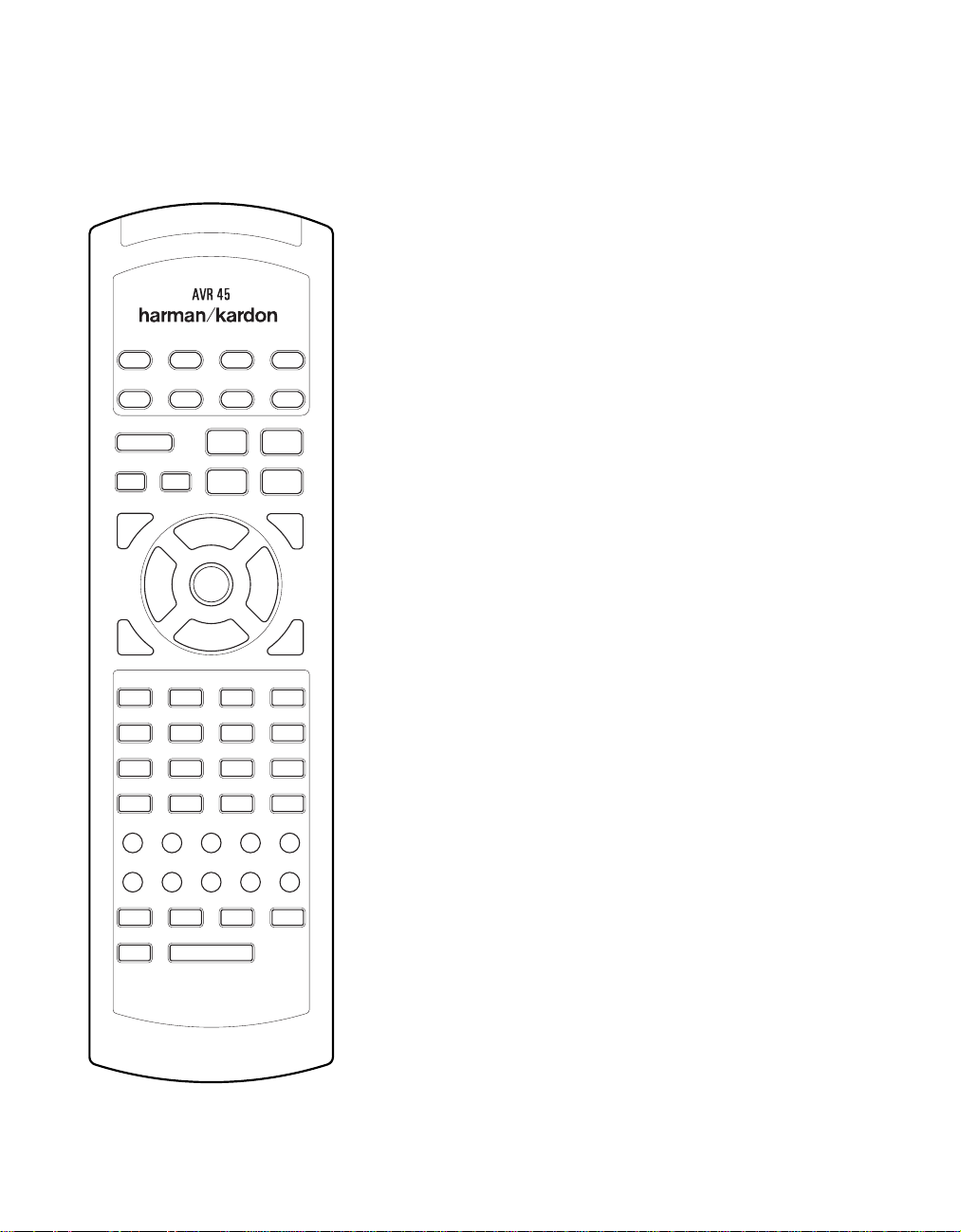
Programmation de la télécommande
123
74
8
56
12
141615
9
10 11
13
17
21 22 23 24
28272625
29
33 34 35 36 37
42
43 44 45 46
4847
41403938
30 31 32
18 19 20
30
Pour déterminer la fonction d’une touche
particulière pour un appareil donné,
chercher le numéro de la touche dans la
“liste des fonctions”, puis lire dans la colonne
correspondant à l’appareil que l’on désire
commander . Par exemple, la touche numéro 5
pour l’A VR45 correspond au signal audio
de test (Test Tone), mais elle représente la
touche “Favorite” (favori) pour beaucoup de
magnétoscopes et récepteurs satellite. La touche
numéro 31 correspond à la touche “Preset Tune
Down” pour l’A VR45, à la touche “Reverse Skip”
pour les lecteurs CD, et à la touche “Page Down”
pour les boîtes de certains réseaux câblés.
Remarque sur l’utilisation de la
télécommande de l’AVR45 pour
d’autres appareils.
• Les fabricants peuvent utiliser des groupes de
codes différents pour la même catégorie de
produit. Pour cette raison, il est important de
vérifier si les codes programmés effectuent le
maximum de commandes possibles. Si on
trouve que seules quelques commandes
fonctionnent, vérifier si un autre groupe de
codes fonctionne avec plus de touches.
• Lorsqu’on appuie sur une touche de la
télécommande de l’A VR45, la lampe rouge
Device Control Selectorb
sous le
pour l’appareil qu’on veut utiliser doit
clignoter brièvement. Si le sélecteur Device
Control clignote pour quelques touches, mais
pas pour toutes, pour un appareil donné, cela
NE signifie PAS qu’il y ait un problème au
niveau de la télécommande, mais plutôt
qu’aucune fonction n’a été programmée
pour la touche sur laquelle on a appuyé.
Programmation Macro
La touche Power peut être programmée pour
envoyer une séquence comportant jusqu’à
huit commandes lorsqu’on appuie dessus.
Ceci permet d’allumer un certain nombre
d’appareils, et d’assigner à une source de
programmes une chaîne favorie, ou toute autre
commande. Pour programmer une macro dans
la touche Power , suivre les étapes suivantes:
1. Appuyer en même temps sur n’importe
quelle touche de
Selectorsb et sur la touche Mute
Device Control
d, jusqu’à ce que la lampe rouge sous
le sélecteur Device Control s’allume.
2. Appuyer sur la touche
Powerc et
remarquer que le sélecteur Device Control
clignote une fois.
3. Introduire jusqu’à huit étapes macro, en
appuyant sur la touche
Device Control,
puis sur la touche de fonction pour chaque
étape que l’on veut programmer. Pour
introduire la commande “Power On/Off”
lors de la programmation macro, appuyer
sur la touche
Mute d. NE PAS appuyer
sur la vraie touche Power.
4. Lorsqu’on aura programmé les huit étapes,
appuyer sur la touche
Sleep ` pour
introduire les commandes. La lampe rouge
sous le sélecteur
Selector clignotera puis s’éteindra.
Device Control
Exemple: Pour programmer le téléviseur,
la boîte du réseau câblé, et l’AVR45 de sorte
qu’ils s’allument lorsqu’on appuie sur la
touche Power , il faut d’abord appuyer sans
relâcher sur les touches
Mute d, jusqu’à ce que la lampe
rouge s’allume sous la touche
Ensuite, appuyer sur la touche
AVR a et
AVR.
Mute d
pour introduire la commande Power pour
l’A VR. Appuyer sur le sélecteur
Device Control Selectorb pour
TV
sélectionner le mode TV , puis appuyer de
nouveau sur la touche
Mute d, pour
sélectionner TV Power. Enfin, appuyer sur
le sélecteur
Selector b, puis sur la touche
Mute d pour sélectioner Cable Power.
Appuyer sur la touche
CBL Device Control
Sleep ` pour
introduire les commandes.
Page 80

Programmation de la télécommande
31
Après avoir suivi ces étapes, à chaque fois
que l’on appuie sur la touche
c, la télécommande enverra la
Power
commande Power On/Off.
Pour retirer un programme macro, suivre les
étapes 1, 2 et 4 décrites plus-haut, sans suivre
l’étape 3. Par exemple, pour effacer la macro
qu’on vient d’introduire en mémoire, appuyer
en même temps sur le sélecteur
Control Selectorb et la touche
Mute d jusqu’à ce que la lampe rouge
Device
au-dessous de Device Control Selector s’allume.
Appuyer sur la touche
Sleep `. La lampe rouge sous
touche
Device Control Selectorclignote deux
Powerc, puis sur la
fois pour confirmer l’introduction des données,
puis s’éteint.
Commande “Volume PunchThrough”
La télécommande de l’A VR45 peut être
programmée pour piloter la commande
V olume Controlz à partir soit du poste
de TV, soit de l’AVR, afin que le fonctionnement
s’effectue conjointement avec n’importe
lequel des appareils commandés par la
télécommande. Par exemple, puisque l’AVR45
risque fort d’être utilisé comme système de
sonorisation pour le TV (téléviseur), on peut
chercher à commander le volume de l’AVR
bien que la télécommande soit réglée pour faire
fonctionner le TV (téléviseur). Chacune des
commandes du volume de l’AVR ou du
TV (téléviseur) peut être associée à n’importe
quel appareil de la télécommande. Pour
programmer la télécommande pour la fonction
Volume Punch-Through, suivre les étapes
suivantes:
1. Appuyer en même temps sur le
Control Selectorb pour l’unité
Device
que l’on désire associer à la commande
de volume, et sur la touche
Mute d
jusqu’à ce que la lampe rouge s’allume
Device Control Selector.
sous le
2. Appuyer sur la touche
3. Appuyer soit sur
TV Device Control Selector
sélecteur
b, selon qu’on veuille rattacher la
V olume Upz.
AVR a, soit sur le
commande de volume de l’un ou l’autre
au mode Punch-Through. Remarquer que
la lampe rouge sous
Selector clignotera deux fois pour
Device Control
confirmer l’introduction des données,
puis s’éteindra.
Exemple - Pour rendre la commande
du volume de l’A VR pilotable bien que la
télécommande soit réglée sur TV ,
commencer d’abord par appuyer en
même temps sur le sélecteur
Device Control Selectorb
TV
et sur la touche Mute d. Ensuite,
appuyer sur la touche
z, puis sur le sélecteur A VR De vice
Control Selectora.
V olume Up
REMARQUE: si l’on désire replacer la
télécommande sur la configuration originale
après avoir programmé un mode Volume
Punch-Through, on doit répéter les opérations
des étapes ci-dessus. Cependant, appuyer sur le
mêmesélecteur Device Control des étapes un
et trois.
Réassignement des sélecteurs
Device Control
Bien que chacun des septs sélecteurs Device
Control Selectorsb est normalement
assigné à la catégorie de produit indiquée sur
la télécommande, il est possible de réassigner
l’une de ces touches pour commander un
second appareil d’un autre type. Par exemple,
si l’on possède deux VCR (magnétoscopes),
mais non un récepteur satellite, on peut
programmer la touche “SAT” pour piloter un
second VCR (magnétoscope). Avant de suivre
les étapes normales de programmation, soit
pour l’introduction de codes à trois chiffres,
soit à l’aide de la fonction Auto Search, on doit
d’abord réassigner la touche en suivant les
étapes suivantes:
1. Appuyer en même temps sur le sélecteur
Device Control Selectorb que
l’on désire réassigner, et sur la touche the
Mute d jusqu’à ce que la lampe rouge
s’allume sous le sélecteur
Control Selector.
2. Appuyer sur le sélecteur
Selector b pour la fonction que l’on
Device
Device Control
désire programmer dans la touche
réassignée.
3. Introduire le code à trois chiffres pour le
modèle particulier que l’on désire faire
fonctionner à l’aide de la touche réassignée.
4. Appuyer de nouveau sur le même sélecteur
Device Control Selectoractionné
durant l’étape 1 pour mémoriser la
sélection.
Exemple - Pour utiliser la touche SAT
pour faire fonctionner un second VCR
(magnétoscope), appuyer d’abord en
même temps sur le sélecteur
Device Control Selectorb,
et sur la touche
Mute d jusqu’à ce
SA T
que la lampe rouge s’allume sous la
touche SAT. Appuyer sur la touche VCR,
puis introduire le code à trois chiffres
pour le modèle particulier que l’on désire
contrôler . Enfin, appuyer de nouveau sur
la touche SAT.
Page 81

Programmation de la télécommande
32
Liste des fonctions
No. Nom de touche CD Tape Aux (DVD) TV VCR CBL SAT
1 Power On/Off Power Power On/Off Power On/Off Power On/Off Power On/Off
2 Sleep Skip+ CH+ CH+ CH+
3 Vol UP Vol+ Vol+ Vol+ Vol+ Vol+
4 Mute Mute Mute Mute Mute
5 Test Tone Fav Fav
6 Surr Skip– CH– CH– CH–
7 Vol Down Vol– Vol– Vol– Vol– Vol–
8 Multiroom Guide Display Guide Guide
9 Speaker Intro Scan Menu Menu Menu Menu
10 Night Clear Exit Exit Exit
11 Delay Open/Close Return Prev CH Prev CH Prev CH
12 Level +/UP Disk Skip + Up Up Up Up
13 Level –/Down Disk Skip – Down Down Down Down
14 Digital Right Right Right Right
15 Channel Left Left Left Left
16 Set Select Select Select Select
17 AM/FM Sub On/Off Music Alt
18 CD
19 Rec/Pause Pause Record/Pause Rec
20 Stop Stop Stop Stop Stop
21 Tape Open/Close
22 Vid 1
23 Rev Play
24 Fwd Play
25 DVD
26 Vid 2
27 Tuning Down
28 Tuning Up
29 6 CH
30 Vid 3
31 Preset Down
32 Preset Up
33 1 1111
34 2 2222
35 3 3333
36 4 4444
37 5 5555
38 6 6666
39 7 7777
40 8 8888
41 9 9999
42 0 0000
43 Direct Time Enter Enter Enter Enter
44 Memory Repeat Sleep PPV
45 FM Mode Random Play TV/VCR TV/VCR Switch TV/SAT
46 Clear + 10 Bypass Next
47 Info
48 Light Display Info Info
fi
fl
·
Play Fwd Play Play Play
Rev Play
‚
Rev Search Rew Search – Rew Day –
—
Fwd Search FF Search + FF Day
‡
Rev Skip Page –
Fwd Skip Pause Pause Page +
Page 82

Programmation de la télécommande
123
74
8
56
12
141615
9
10 11
13
17
21 22 23 24
28272625
29
33 34 35 36 37
42
43 44 45 46
4847
41403938
30 31 32
18 19 20
Références pour la liste des fonctions
33
Page 83

Programmation de la télécommande
34
Tableaux des codes de réglage: TV
Fabricant/Marque Numéro du code de réglage
A MARK 112
ADMIRAL 072 081 161
AKAI 001 167
AMPRO 073 167
ANAM 043 054 055 056 080 104 108 112 118 121
AOC 001 004 058 112
CANDLE 001 002 003 004
CAPEHART 058
CENTRONIC 043
CITIZEN 001 002 003 004 101 143
CLASSIC 043
CONCERTO 004
CONTEC 043 051
CORONADO 143
CRAIG 054
CROWN 143
CURTIS MATHES 001 004 101 143
CXC 043
DAEWOO 004 055 103 111 114 127 143
DAYTRON 004 143
DWIN 177
DYNASTY 043
DYNATECH 062
ELECTROHOME 024 143
EMERSON 001 004 005 028 043 047 048 051 096 143 151 153 154 155
FISHER 007 057
FUNAI 028 043
FUTURETECH 043
GE 004 008 009 034 056 073 074 091 130 144 155 160 161
GOLDSTAR 004 106 110 112 113 119 127 143
HALL MARK 004
HITACHI 004 007 010 011 012 023 075 143 158 163
INFINITY 164
INKEL 129
JBL 164
JCP 001
Page 84

Programmation de la télécommande
35
Tableaux des codes de réglage: TV (Suite)
Fabricant/Marque Numéro du code de réglage
JC PENNY 004 008 024 030 065 101 143 160
JENSEN 013
JVC 034 038 070 083
KENWOOD 001 070
KLOSS 002 059
KTV 043 143 154
LODGENET 072
LOGIK 072
LUXMAN 004
LXI 007 015 052 081 160 164
MAGNAVOX 001 003 004 022 059 060 061 063 064 127 164
MARANTZ 001 164
MATSUI 164
MEMOREX 004 007 072
METZ 088
MGA 001 004 024 042
MINERVA 088
MITSUBISHI 004 024 040 042 109 146
MTC 001 004 062 101
NAD 015 025
NEC 001 019 024 040 056 130 134
NIKEI 043
ONKING 043
ONWA 043
OPTONICA 019 081
PANASONIC 034 056 080 164
PHILCO 001 003 004 024 056 059 060 063 064 127 143 164
PHILIPS 001 003 004 005 038 059 093 164
PIONEER 004 018 023 025 135 176
PORTLAND 004 143
PROSCAN 144 160 161 167
PROTON 004 058 143 171 173
QUASAR 034 056
RADIO SHACK 004 019 047 127 143
RCA 001 004 023 024 056 065 074 144 152 156 160 161
Page 85

Programmation de la télécommande
36
Tableaux des codes de réglage: TV (Suite)
Fabricant/Marque Numéro du code de réglage
REALISTIC 007 019 047
RUNCO 072 169
SAMPO 001 004 058
SAMSUNG 004 101 127 133 143 160
SANYO 007 020 021 033 053 057 082
SCOTT 004 028 043 048 143
SEARS 004 007 015 028 030 057 082 094 143 160
SHARP 004 014 019 022 028 143 175
SIGNATURE 072
SONY 070 085 126 139
SOUNDESIGN 003 004 028 043
SPECTRICON 112
SSS 004 043
SUPRE MACY 002
SYLVANIA 001 003 059 060 063 064 127 160 164
SYMPHONICS 052
TANDY 081
TATUNG 056 062
TECHNICS 034 080
TECHWOOD 004
TENIKA 002 003 004 028 043 072 101 143
TELERENT 072
TERA 172
TMK 004
TOSHIBA 015 030 040 062 101
TOTEVISION 143
UNIVERSAL 008 009
VIDEO CONCEPTS 146
VIDIKRON 174
VIDTECH 004
WARDS 004 008 009 019 028 060 061 063 064 072 074 164
YAMAHA 004
YORK 004
YUPITERU 043
ZENITH 072 073 095 103
ZONDA 112
Page 86

Programmation de la télécommande
37
Tableaux des codes de réglage: Magnétoscopes (VCR)
Fabricant/Marque Numéro du code de réglage
AIWA 034
AMPRO 072
ANAM 031 103
AUDIO DYNAMICS 012 023 043
BROKSONIC 035 037 129
CANON 028 031
CAPEHART 108
CRAIG 001 040 135
CURTIS MATHES 031 041
DAEWOO 007 010 017 065 108 111
DAYTRON 108
DBX 012 023 043
DYNATECH 034 053
ELECTROHOME 059
EMERSON 006 017 025 027 029 031 034 035 036 037 046 101 129 131 138 153
FISHER 001 008 009 010
FUNAI 034
GE 031 063 072 107 109 144 147
GO VIDEO 132 136
GOLDSTAR 004 012 020 101
HARMAN KARDON 012 045
HITACHI 018 026 034 043 063 137 150
INSTANTREPLAY 031
JCL 031
JC PENNY 004 012 040 101
JENSEN 043
JVC 012 031 043 046 055 060 130 150 152
KENWOOD 014 034 048
LLOYD 034
LXI 001 004 009 017 034
MAGIN 040
MAGNAVOX 031 034 041 067 068
MARANTZ 012 031 067 069
MARTA 101
MATSUI 027 030
MEI 031
MEMOREX 001 010 014 031 034 040 053 072 101 134 139
MGA 045 046 059
MINOLTA 004 020
MITSUBISHI 004 020 046 051 059 061 142
MTC 034 040
MULTITECH 024 034
NEC 012 023 043 048
MORDMENDE 043
Page 87

Programmation de la télécommande
38
Tableaux des codes de réglage: Magnétoscopes (VCR) (Suite)
Fabricant/Marque Numéro du code de réglage
OPTONICA 053 054
PANASONIC 070 133 140
PENTAX 004 020 031 063
PHILCO 031 034 067
PHILIPS 031 034 054 067 101
PILOT 101
PIONEER 004 021 048
PORTLAND 108
PULSAR 072
QUARTZ 014
RCA 004 020 034 040 041 107 109 140 144 147
REALISTIC 001 008 010 014 031 034 040 053 054 101
RICO 058
RUNCO 072
SALORA 014
SAMSUNG 017 040 107 109 113 115 124
SANSUI 043 048 135
SANYO 001 007 010 014 040 134
SCOTT 017 037 129 131
SEARS 001 004 008 009 010 014 017 020 081 101
SHARP 031 054
SHINTOM 024
SONY 001 009 031 052 056 057 058
SOUNDESIGN 034
STS 004
SYLVANIA 031 034 059 067
SYMPHONIC 034
TANDY 010 034
ATATUNG 043
TEAC 034 043
TECHNICS 031 070
TEKNIKA 031 034 101
THOMAS 034
TMK 006
TOSHIBA 004 008 017 059 082 131
TOTEVISION 040 101
UNITECH 040
VECTOR RESEARCH 012
VICTOR 048
VIDEO CONCEPTS 012 034 046 141
VIDEOSONIC 040
WARDS 001 004 017 024 031 034 040 053 054 131
YAMAHA 012 034 043
ZENITH 034 048 056 058 072 080 101
Page 88

Programmation de la télécommande
39
Tableaux des codes de réglage: CD
Fabricant/Marque Numéro du code de réglage
ADCOM 062 042
AIWA 187 170
AKAI 202 195
CARVER 003 167 041 135 138 139 050 203
DENON 205 226
HARMAN KARDON 047 033 208 001 002
JVC 022 136 163
KENWOOD 007 055 023 137 072 142
MARANTZ 107 044
MONDIAL 147
NAD 215 005
NAKAMICHI 217 218 219
ONKYO 038 168 030
OPTIMUS 049 085
PANASONIC 068
PIONEER 010 020 174
REALISTIC 181 187 102
RCA 012 150
SHARP 013 051 066 031
SHERWOOD 166 112 115 119 093
SONY 225 097 126 133 081
TEAC 062 131 015 182
TECHNICS 068 200 008 060
YAMAHA 012 054 024
Tableaux des codes de réglage: AUX (DVD)
Fabricant/Marque Numéro du code de réglage
DENON 001
LG 010
MAGNAVOX 012
MITSUBISHI 002
PANASONIC 003
PHILIPS 012
PIONEER 004
PROSCAN 005
RCA 006
SAMSUNG 011
SONY 007
TOSHIBA 008
YAMAHA 009
Page 89

Programmation de la télécommande
40
Tableaux des codes de réglage: CABLE
Fabricant/Marque Numéro du code de réglage Modèle de télécommande
PIONEER 001 BR-200
AMERICAST 005
JERROLD 006 RT-J22 (CFT2200)
JERROLD 007 RT-J550C
PIONEER 002 BR-95
PIONEER 003 RT-P81/82
SCIENTIFIC-ATLANTIC 004 RT-S6X/USV86
TOCOM 010 RT-T7/T8
ZENITH 008 MN2500
ZENITH 009 RT-ZPMV
Tableaux des codes de réglage: SAT
Manufacturer/Brand Setup Code Number
GE 001
ALPHASTAR 007
ECHOSTAR 006
HITACHI 001 012
HUGHES 003
PANASONIC 013
PRIMESTAR 002
PRIMESTAR 005
RCA 001
SONY 004
TOSHIBA 008
UNIDEN 009 010
Page 90

Guide de dépannage
Guide de dépannage
41
SYMPTOME
Lumières absentes après avoir appuyé
sur l’interrupteur d’alimentation
L ’écran s’allume, mais pas de son et
pas d’image
Son absent sur tous les hauts-parleurs.
La lumière autour de l’interrupteur
d’alimentation est rouge
Son absent sur les hauts-parleurs de
réverbation et de la voie centrale
L ’unité ne répond pas à la
télécommande
ORIGINE
• L ’appareil n’est pas sous tension
• Intermittence dans les connexions
d’entrée
• Fonction
• Commande du volume à zéro
• Amplificateur se trouvant en mode
• Amplificateur en mode protégé suite à
• Mode de réverbation incorrect
• Entrée monaurale
• Configuration incorrecte
• Programme en Stéréo ou Mono
• Piles faibles sur la télécommande
• Sélection erronée d’appareil
• Cellule de réception de télécommande
Mute (suppression du son)
activée
protégé du fait d’un éventuel court-circuit
des problèmes internes
cachée
SOLUTION
• S’assurer que le cordon d’alimentation est inséré dans une
prise secteur active
• Vérifier si la prise n’est pas directe (non commandée par
un interrupteur)
• S’assurer que toutes les connexions d’entrée et des
hauts-parleurs sont bien serrées
• Appuyer sur la touche
• Augmenter la commande du volume
• Vérifier les connexions des hauts-parleurs au niveau du
récepteur et au niveau de leurs bornes pour éliminer tout
court-circuit
• Contacter le service local de dépannage Harman Kardon
• Sélectionner un mode autre que le mode Stéréo
• Il n’y a pas d’informations de réverbation provenant des
sources mono
• Vérifier le mode de sortie HP
• Le décodeur de réverbation ne peut créer les informations
de la voie centrale ou des voies postérieures à partir de
programmes non codés
• Remplacer les piles de la télécommande
• Appuyer sur le sélecteur
• S’assurer que la cellule de réception du panneau frontal
est “visible” par la télécommande, ou raccorder une
cellule externe
Mute
AVR
Bourdonnementintermittent
dans le tuner
• Interférences locales
• Eloigner l’unité ou l’antenne des ordinateurs, tubes
fluorescents, moteurs, ou appareils électroménagers
Page 91

Caractéristiques techniques
42
Section audio
Mode Stéréo
Puissance moyenne continue (FTC)
65 Watts par voie 20Hz–20kHz:
@ < 0,07% THD, les deux voies sur 8 ohms
Mode Surround 5 voies
Puissance par voie individuelle
Voies frontales gauche et droite:
55 Watts par voie,
@ < 0,07% THD, 20Hz–20kHz sur 8 ohms
Voie centrale:
55 Watts, @ < 0,07% THD, 20Hz–20kHz sur 8 ohms
Voies Surround:
55 Watts par voie,
@ < 0,07% THD, 20Hz–20kHz sur 8 ohms
Sensibilité/ Impédance d’entrée
Linéaire (Niveau élevé) 200mV/47 kohms
Rapport signal/bruit (IHF-A) 95dB
Séparation de la voie adjacente du système Surround
Décodage analogique (Pro Logic, etc.) 40dB
Dolby Digital (AC-3) 55dB
Réponse en fréquence
@ 1W (+0dB, –3dB) 8Hz–80kHz
Courant instantané
De crête (HCC) ±35 Amps
Transient Intermodulation
Distorsion (TIM) Négligeable
Temps de montée 16µsec
Vitesse de saut 40V/µsec
Section Tuner FM
Gamme de fréquences 87,5–108MHz
Sensibilité utile IHF 1,3 µV/13,2dBf
Rapport signal/Bruit Mono/Stereo 70/68dB
Distorsion Mono/Stereo 0,3/0,5%
Séparation stéréo 40dB @ 1kHz
Selectivité ±400kHz, 65dB
Réjection d’image 80dB
Réjection IF 90dB
Niveau de sortie du tuner 1kHz, ±75kHz Dev 500mV
Section Tuner AM
Gamme de fréquences 520–1710kHz
Rapport Signal/Bruit 45dB
Sensibilité utile Loop 500µV
Distorsion 1kHz, 50% Mod 0.8%
Selectivité ±10kHz, 30dB
Section vidéo
Format vidéo NTSC
Niveau d’entrée/Impédance 1Vp-p/75 ohms
Niveau de sortie/Impédance 1Vp-p/75 ohms
Réponse de la fréquence vidéo 10Hz–8MHz (–3dB)
Caractéristiques générales
Tension d’alimentation Courant alternatif 120V/60Hz
Puissance consommée 72W à vide, 332W maximum
(2 voies)
Dimension (Max)
Largeur 17,3 pouces (440mm)
Hauteur 6,5 pouces (165mm)
Profondeur 17,1 pouces (435mm)
Poids 29 livres. (13.2 kg)
L’évaluation de la profondeur prend en compte les boutons et les bornes de branchement.
L’évaluation de la hauteur prend en compte les pastilles-support et le châssis.
Les caractéristiques et spécifications peuvent être modifiées sans préavis.
*Fabriqué sous license Dolby Laboratories.
“Dolby”, “Pro Logic” et le symbole Double-D sont des marques
de commerce de Dolby Laboratories. Travaux non publiés et confidentiels.
©
1992–1998 Dolby Laboratories, Inc. Tous droits réservés.
†
DTS est une marque commerciale de Digital Theater Systems.
††
UltraStereo est une marque commerciale de UltraStereo Corp.
Page 92

Remarques
43
. . . . . . . . . . . . . . . . . . . . . . . . . . . . . . . . . . . . . . . . . . . . . . . . . . . . . . . . . . . . . . . . . . . . . . . . . . . . . . . . . . . .
. . . . . . . . . . . . . . . . . . . . . . . . . . . . . . . . . . . . . . . . . . . . . . . . . . . . . . . . . . . . . . . . . . . . . . . . . . . . . . . . . . . .
. . . . . . . . . . . . . . . . . . . . . . . . . . . . . . . . . . . . . . . . . . . . . . . . . . . . . . . . . . . . . . . . . . . . . . . . . . . . . . . . . . . .
. . . . . . . . . . . . . . . . . . . . . . . . . . . . . . . . . . . . . . . . . . . . . . . . . . . . . . . . . . . . . . . . . . . . . . . . . . . . . . . . . . . .
. . . . . . . . . . . . . . . . . . . . . . . . . . . . . . . . . . . . . . . . . . . . . . . . . . . . . . . . . . . . . . . . . . . . . . . . . . . . . . . . . . . .
. . . . . . . . . . . . . . . . . . . . . . . . . . . . . . . . . . . . . . . . . . . . . . . . . . . . . . . . . . . . . . . . . . . . . . . . . . . . . . . . . . . .
. . . . . . . . . . . . . . . . . . . . . . . . . . . . . . . . . . . . . . . . . . . . . . . . . . . . . . . . . . . . . . . . . . . . . . . . . . . . . . . . . . . .
. . . . . . . . . . . . . . . . . . . . . . . . . . . . . . . . . . . . . . . . . . . . . . . . . . . . . . . . . . . . . . . . . . . . . . . . . . . . . . . . . . . .
. . . . . . . . . . . . . . . . . . . . . . . . . . . . . . . . . . . . . . . . . . . . . . . . . . . . . . . . . . . . . . . . . . . . . . . . . . . . . . . . . . . .
. . . . . . . . . . . . . . . . . . . . . . . . . . . . . . . . . . . . . . . . . . . . . . . . . . . . . . . . . . . . . . . . . . . . . . . . . . . . . . . . . . . .
. . . . . . . . . . . . . . . . . . . . . . . . . . . . . . . . . . . . . . . . . . . . . . . . . . . . . . . . . . . . . . . . . . . . . . . . . . . . . . . . . . . .
. . . . . . . . . . . . . . . . . . . . . . . . . . . . . . . . . . . . . . . . . . . . . . . . . . . . . . . . . . . . . . . . . . . . . . . . . . . . . . . . . . . .
. . . . . . . . . . . . . . . . . . . . . . . . . . . . . . . . . . . . . . . . . . . . . . . . . . . . . . . . . . . . . . . . . . . . . . . . . . . . . . . . . . . .
. . . . . . . . . . . . . . . . . . . . . . . . . . . . . . . . . . . . . . . . . . . . . . . . . . . . . . . . . . . . . . . . . . . . . . . . . . . . . . . . . . . .
. . . . . . . . . . . . . . . . . . . . . . . . . . . . . . . . . . . . . . . . . . . . . . . . . . . . . . . . . . . . . . . . . . . . . . . . . . . . . . . . . . . .
. . . . . . . . . . . . . . . . . . . . . . . . . . . . . . . . . . . . . . . . . . . . . . . . . . . . . . . . . . . . . . . . . . . . . . . . . . . . . . . . . . . .
. . . . . . . . . . . . . . . . . . . . . . . . . . . . . . . . . . . . . . . . . . . . . . . . . . . . . . . . . . . . . . . . . . . . . . . . . . . . . . . . . . . .
. . . . . . . . . . . . . . . . . . . . . . . . . . . . . . . . . . . . . . . . . . . . . . . . . . . . . . . . . . . . . . . . . . . . . . . . . . . . . . . . . . . .
. . . . . . . . . . . . . . . . . . . . . . . . . . . . . . . . . . . . . . . . . . . . . . . . . . . . . . . . . . . . . . . . . . . . . . . . . . . . . . . . . . . .
. . . . . . . . . . . . . . . . . . . . . . . . . . . . . . . . . . . . . . . . . . . . . . . . . . . . . . . . . . . . . . . . . . . . . . . . . . . . . . . . . . . .
. . . . . . . . . . . . . . . . . . . . . . . . . . . . . . . . . . . . . . . . . . . . . . . . . . . . . . . . . . . . . . . . . . . . . . . . . . . . . . . . . . . .
Page 93

Remarques
44
. . . . . . . . . . . . . . . . . . . . . . . . . . . . . . . . . . . . . . . . . . . . . . . . . . . . . . . . . . . . . . . . . . . . . . . . . . . . . . . . . . . .
. . . . . . . . . . . . . . . . . . . . . . . . . . . . . . . . . . . . . . . . . . . . . . . . . . . . . . . . . . . . . . . . . . . . . . . . . . . . . . . . . . . .
. . . . . . . . . . . . . . . . . . . . . . . . . . . . . . . . . . . . . . . . . . . . . . . . . . . . . . . . . . . . . . . . . . . . . . . . . . . . . . . . . . . .
. . . . . . . . . . . . . . . . . . . . . . . . . . . . . . . . . . . . . . . . . . . . . . . . . . . . . . . . . . . . . . . . . . . . . . . . . . . . . . . . . . . .
. . . . . . . . . . . . . . . . . . . . . . . . . . . . . . . . . . . . . . . . . . . . . . . . . . . . . . . . . . . . . . . . . . . . . . . . . . . . . . . . . . . .
. . . . . . . . . . . . . . . . . . . . . . . . . . . . . . . . . . . . . . . . . . . . . . . . . . . . . . . . . . . . . . . . . . . . . . . . . . . . . . . . . . . .
. . . . . . . . . . . . . . . . . . . . . . . . . . . . . . . . . . . . . . . . . . . . . . . . . . . . . . . . . . . . . . . . . . . . . . . . . . . . . . . . . . . .
. . . . . . . . . . . . . . . . . . . . . . . . . . . . . . . . . . . . . . . . . . . . . . . . . . . . . . . . . . . . . . . . . . . . . . . . . . . . . . . . . . . .
. . . . . . . . . . . . . . . . . . . . . . . . . . . . . . . . . . . . . . . . . . . . . . . . . . . . . . . . . . . . . . . . . . . . . . . . . . . . . . . . . . . .
. . . . . . . . . . . . . . . . . . . . . . . . . . . . . . . . . . . . . . . . . . . . . . . . . . . . . . . . . . . . . . . . . . . . . . . . . . . . . . . . . . . .
. . . . . . . . . . . . . . . . . . . . . . . . . . . . . . . . . . . . . . . . . . . . . . . . . . . . . . . . . . . . . . . . . . . . . . . . . . . . . . . . . . . .
. . . . . . . . . . . . . . . . . . . . . . . . . . . . . . . . . . . . . . . . . . . . . . . . . . . . . . . . . . . . . . . . . . . . . . . . . . . . . . . . . . . .
. . . . . . . . . . . . . . . . . . . . . . . . . . . . . . . . . . . . . . . . . . . . . . . . . . . . . . . . . . . . . . . . . . . . . . . . . . . . . . . . . . . .
. . . . . . . . . . . . . . . . . . . . . . . . . . . . . . . . . . . . . . . . . . . . . . . . . . . . . . . . . . . . . . . . . . . . . . . . . . . . . . . . . . . .
. . . . . . . . . . . . . . . . . . . . . . . . . . . . . . . . . . . . . . . . . . . . . . . . . . . . . . . . . . . . . . . . . . . . . . . . . . . . . . . . . . . .
. . . . . . . . . . . . . . . . . . . . . . . . . . . . . . . . . . . . . . . . . . . . . . . . . . . . . . . . . . . . . . . . . . . . . . . . . . . . . . . . . . . .
. . . . . . . . . . . . . . . . . . . . . . . . . . . . . . . . . . . . . . . . . . . . . . . . . . . . . . . . . . . . . . . . . . . . . . . . . . . . . . . . . . . .
. . . . . . . . . . . . . . . . . . . . . . . . . . . . . . . . . . . . . . . . . . . . . . . . . . . . . . . . . . . . . . . . . . . . . . . . . . . . . . . . . . . .
. . . . . . . . . . . . . . . . . . . . . . . . . . . . . . . . . . . . . . . . . . . . . . . . . . . . . . . . . . . . . . . . . . . . . . . . . . . . . . . . . . . .
. . . . . . . . . . . . . . . . . . . . . . . . . . . . . . . . . . . . . . . . . . . . . . . . . . . . . . . . . . . . . . . . . . . . . . . . . . . . . . . . . . . .
. . . . . . . . . . . . . . . . . . . . . . . . . . . . . . . . . . . . . . . . . . . . . . . . . . . . . . . . . . . . . . . . . . . . . . . . . . . . . . . . . . . .
Page 94

DIGITAL
COAX AC-3
AVR 45
CDTAPE DVD VID 1 VID 2 VID 3 6 CHANNEL AM/FM PRETUNNING
Phones
Power
Printed in Korea Part #1111-AVR45OM
6311-0003-010
 Loading...