

Page 1
Ref
Volume
Wrap
Contour
Monitor
Bass Treble Balance
Video 3
Video L–Audio–R
KHz
MHz
TUNED AUTO TAPE M
HALL
SLEEP
PRESET
STEREO
Pro Logic
ms
Harman Kardon
AVR40
Audio/VideoReceiver
Owner’s Manual
Page 2

Owner’s Manual
AVR40 Audio/Video Receiver
Table of Contents
Introduction . . . . . . . . . . . . . . . . . . . . . . . . . . . . . . . . . . 1
Features . . . . . . . . . . . . . . . . . . . . . . . . . . . . . . . . 1
Safety Information. . . . . . . . . . . . . . . . . . . . . . . . . . . . 2-3
Unpacking and Installation . . . . . . . . . . . . . . . . 3
Conventions. . . . . . . . . . . . . . . . . . . . . . . . . . . . . 3
Front Panel Controls . . . . . . . . . . . . . . . . . . . . . . . . . . 4-6
Rear Panel Connections . . . . . . . . . . . . . . . . . . . . . . . 7-8
Remote Control Functions . . . . . . . . . . . . . . . . . . . . 9-10
Installation and Configuration . . . . . . . . . . . . . . . . 11-14
Operation . . . . . . . . . . . . . . . . . . . . . . . . . . . . . . . . . 15-18
Wrap Circuitry . . . . . . . . . . . . . . . . . . . . . . . 16-17
Tuner Operation. . . . . . . . . . . . . . . . . . . . . . 17-18
Tape Recording. . . . . . . . . . . . . . . . . . . . . . . . . 18
Video Dubbing. . . . . . . . . . . . . . . . . . . . . . . . . . 18
Troubleshooting Chart . . . . . . . . . . . . . . . . . . . . . . . . . 19
Technical Specifications . . . . . . . . . . . . . . . . . . . . . . . . 20
80 Crossways Park West
Woodbury, NY 11797
www.harmankardon.com
©1997 Harman Kardon, Incorporated
Page 3

Staple or clip original invoice here. ▼
Page 4

Introduction
1
Congratulations! With the purchase
of a Harman Kardon AVR40 you are
about to begin many years of listening
enjoyment. The AVR40 has been custom
designed to provide all the excitement
and detail of movie soundtracks and
every subtle nuance of musical
selections.
While complex systems are hard at work
within the AVR40 to make all of this happen, hookup and operation are simple.
Color keyed connections, and a unique
remote control make the AVR40 easy to
use. To obtain the maximum enjoyment
from your new receiver we urge you to
take a few minutes to read through this
manual. This will ensure that connections to speakers, source playback units
and other external devices are made
properly. A few minutes spent learning
the functions of the various controls will
enable you to take advantage of all the
power the AVR40 is able to deliver.
If you have any questions about this
product, its installation or operation,
please contact your dealer. They are your
best local source of information. You
may also contact Harman Kardon
directly via the Internet at
www.harmankardon.com
Description and Features
The AVR40 is a full featured A/V receiver,
incorporating a wide variety of listening
options. Four audio inputs, three
audio/video inputs and the AVR40’s 30
preset tuner enable it to serve as the control center for a complete audio/video
system. A system remote control operates
the AVR40 and compatible Harman
Kardon source equipment.
■ Dolby* Pro Logic* Surround
Decoding
■ Exclusive Harman Kardon Wrap
Circuitry
■ System Remote Control
■ Direct Video Dubbing
■ Front Panel A/V Inputs for Games
or Camcorder Connection
■ System Memory for Surround
Modes
Page 5
Safety Information
CAUTION:
TO REDUCE THE RISK OF ELECTRIC SHOCK, DO NOT REMOVE
COVER (OR BACK). NO USER-SERVICEABLE PARTS INSIDE. REFER
SERVICING TO QUALIFIED SERVICE PERSONNEL.
WARNING:
TO REDUCE THE RISK OF FIRE OR ELECTRIC SHOCK,
DO NOT EXPOSE THIS APPLIANCE TO RAIN OR MOISTURE.
CAUTION:
TO PREVENT ELECTRIC SHOCK, MATCH WIDE
BLADE OF PLUG TO WIDE SLOT, FULLY INSERT.
ATTENTION:
POUR EVITER LES CHOCS ELECTRIQUES, INRODUIRE LA
LAME LA PLUS LARGE DE LA FICHE DANS LA BORNE CORRESPONDANTE DE
LA PRISE ET POUSSER JUSQU'AU FOND.
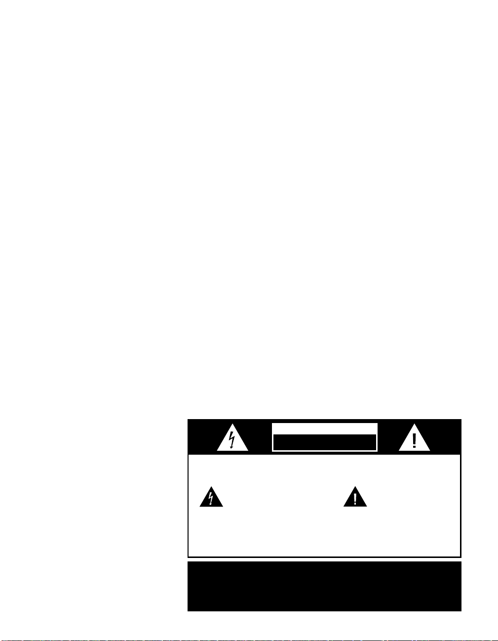
The lightning flash with arrowhead
symbol, within an equilateral triangle, is
intended to alert the user to the
presence of uninsulated “dangerous voltage”
within the product’s enclosure that may be of
sufficient magnitude to constitute a risk of
electric shock to persons.
The exclamation point within an
equilateral triangle is intended to
alert the user to the presence of
important operating and maintenance
(servicing) instructions in the literature
accompanying the appliance.
CAUTION
RISK OF ELECTRIC SHOCK
DO NOT OPEN
2
Important Safety Information
Verify Line Voltage Before Use
Your AVR40 has been designed foruse in
North America with 120 volt AC current.
Connection to a line voltage other than
that for which it is intended can create a
safety and fire hazard, and may damage
the amplifier.
If you have any questions about the voltage requirements for your specific model,
or about the line voltage in your area,
contact your dealer before plugging the
unit into a wall outlet.
Do Not Use Extension Cords
To avoid safety hazards, use only the
power cord supplied with your unit. If a
replacement cord is used, make certain
that it is of similar gauge. We do not recommend that extension cords be used
with this product. As with all electrical
devices, do not run power cords under
rugs or carpets or place heavy objects on
them. Damaged power cords should be
replaced immediately with cords meeting
factory specifications.
CATV Or Antenna Grounding
If an outside antenna or cable system is
connected to this product, be certain that
it is grounded so as to provide some protection against voltage surges and static
charges. Section 810 of the National
Electrical Code, ANSI/NFPA No. 70-1984,
provides information with respect to
proper grounding of the mast and supporting structure, grounding of the leadin wire to an antenna discharge unit,
size of grounding conductors, location of
antenna discharge unit, connection to
grounding electrodes and requirements
of the grounding electrode.
NOTE TO CATV SYSTEM INSTALLER:
This reminder is provided to call the
CATV (Cable TV)system installer’s attention to article 820-40 of the NEC that
provides guidelines for proper grounding
and, in particular, specifies that the cable
ground shall be connected to the grounding system of the building, as close to the
point of cable entry as possible.
Installation Location
■ To assure proper operation, and to
avoid the potential for safety hazards,
place the unit on a firm and level
surface. When placing the unit on a
shelf, be certain that the shelf and
any mounting hardware can support
the weight of the product.
■ Make certain that proper space is pro-
vided both above and below the unit
for ventilation. If this product will be
installed in a cabinet or other enclosed
area, make certain that there is sufficient air movement within the cabinet.
Under some circumstances a fan may
be required.
■ Do not place the unit directly on a
carpeted surface.
■ Avoid installation in extremely hot
or cold locations, or an area that is
exposed to direct sunlight or heating
equipment.
■ Avoid moist or humid locations.
■ Do not obstruct the ventilation slots on
the top of the unit, or place objects
directly over them.
Handle The AC Power Cord Gently
When disconnecting the power cord from
an AC outlet, always pull the plug, never
pull the cord. If you do not intend to use
the amplifier for any considerable length
of time, disconnect the plug from the AC
outlet.
Do Not Open The Cabinet
There are no user serviceable components inside this product. Opening the
cabinet may present a shock hazard, and
any modification to the product will void
your guarantee. If water or any metal
object such as a paper clip, wire or a
staple accidentally falls inside the unit,
disconnect it from the AC power source
immediately, and consult an authorized
service station.
Page 6

Safety Information
3
Cleaning
When the unit gets dirty, wipe it with a
clean, soft dry cloth. If necessary, wipe it
with a soft cloth dampened with mild
soapy water, then a fresh cloth with clean
water. Wipe dry immediately with a dry
cloth. NEVER use benzene, thinner,
alcohol or any other volatile cleaning
agent. Do not use abrasive cleaners, as
they may damage the finish of metal
parts. Avoid spraying insecticide near
the unit.
Moving The Unit
Before moving the unit, be certain to disconnect any interconnection cords with
other components, and make certain
that you disconnect the unit from the AC
outlet.
Important Information For The User
NOTE: This equipment has been tested
and found to comply with the limits for a
Class B digital device, pursuant to Part
15 of the FCC Rules. The limits are
designed to provide reasonable protection
against harmful interference in a residential installation. This equipment
generates, uses and can radiate radio frequency energy and, if not installed and
used in accordance with the instructions,
may cause harmful interference to radio
communication. However, there is no
guarantee that harmful interference will
not occur in a particular installation. If
this equipment does cause harmful interference to radio or television reception,
which can be determined by tuning the
equipment off and on, the user is
encouraged to try to correct the interference by one or more of the following
measures:
■ Reorient or relocate the receiving
antenna.
■ Increase the separation between the
equipment and receiver.
■ Connect the equipment into an outlet
on a circuit different from that to
which the receiver is connected.
■ Consult the dealer or an experienced
radio/TV technician for help.
This device complies with Part 15 of the
FCC Rules. Operation is subject to the following two conditions: (1) this device
may not cause harmful interference, and
(2) this device must accept interference
received, including interference that may
cause undesired operation.
NOTE: Changes or modifications may
cause this unit to fail to comply with
Part 15 of the FCC Rules and may void
the user’s authority to operate the
equipment.
Unpacking and Installation
The carton and shipping materials used
to protect your new AVR40 during shipment were specially designed to cushion
it from shock and vibration. We suggest
that you save the carton and packing
materials for use in shipping if you move
or should the unit ever need repair.
To minimize the size of the carton in
storage, you may wish to flatten it. This
is done by carefully removing any staples
that attach the carton flaps to one
another, and then slitting the tape
covering the seams. Fold the carton down
to a more two dimensional appearance.
Packing materials that cannot be
collapsed should be saved along with the
carton in a plastic bag.
If you do not wish to save the packaging
materials, please note that the carton
and other sections of the shipping protection are recyclable. Please respect the
environment and discard those materials
at a local recycling center.
When positioning your AVR40 in its final
location, make certain that any shelf or
stand is capable of supporting its weight,
and that there is adequate ventilation on
all sides, as well as on the top and bottom. Do not place CDs, record jackets,
owner’s manuals, or other paper on top
of, or beneath the unit. This will block
air flow, causing degraded performance
and a possible fire hazard. If the unit is
to be enclosed in a cabinet or rack, make
certain that there is adequate air circulation, with a means provided for hot air to
exit, and for cool air to be brought in.
Conventions
In order to help you use this manual
with the remote control, front panel
controls, rear panel connections and
on-screen menus, certain conventions
have been used.
BOLD TYPE – will be used to indicate
a front or rear panel control. It will
typically be followed with a reference
number to the specific control being
described.
DISPLAY TYPE – will be used to indi-
cate messages that appear in the information display window.
1 – A number within a Square refer-
ences a front panel control.
¡ – A number within a Circle refer-
ences a connection point on the rear
panel.
a – A number within an Oval refer-
ences a button on the remote control.
Page 7
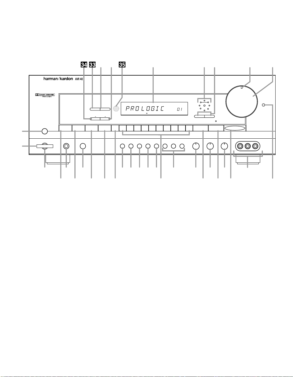
Front Panel Controls
Power
Center Rear Delay Calibrate Memory 1 2 3 4 5 6 7 8 9 0 Surround Ctr. Boost Tuning
Tuning Mode
P
.
Scan
Ref
Volume
Wrap
Contour
AM / FM CD
Speaker
Headpnone
Tape 1 Tape 2 TV Video 1 Video 2 Video 3
Bass Treble Balance
Video 3
Video 2 Video 1 Video 3 Video 1
Video L–Audio–R
KHz
MHz
TUNED AUTO TAPE M
HALL
SLEEP
PRESET
STEREO
Pro Logic
ms
Monitor
1
2
^& * Ó(
6789)345 !@#Ò$
Ú
%
Û
Ùı˜ˆ¯¸˘
Ô
4
1 Main Power Switch
2 System Power Control
3 Power Indicator
4 Headphone Jack
5 Speaker Switch
6 AM/FM Selector
7 CD
8 Tape 1/Tape Monitor
9 Tape 2
) TV
! Video Sources
@ Bass Control
# Treble Control
$ Balance Control
% Video 3
^ Center Channel
& Rear Channel
* Delay Time Adjust
( Calibrate
Ó Tuner Memory Button
Ô Numeric Buttons
Surround Mode
Ò Center Boost
Ú Tuning Button
Û Contour
Ù Volume Control
ı Mute/Volume Indicator
ˆ Wrap
˜ Wrap Indicator
¯ Information Display
˘ Video 3→Video 1 Dubbing
¸ FM Mode
33
P.Scan Button
34
Video 2→Video 1 Dubbing
35
Remote Sensor
Page 8

Front Panel Controls
5
1 Main Power Switch: Press this
button to apply power to the AVR40.
When the switch is pressed the unit
is placed in a Standby mode, as
indicated by the amber LED 3 surrounding the System Power control
2. This button MUST be pressed in
to operate the unit regardless of the
status of the Power Switch at the
bottom of the front panel. To turn the
unit off and prevent the use of the
remote control, this switch should be
pressed until it pops out to extend
from the front panel so that the word
“OFF” may be read at the top of the
switch.
NOTE: In normal operation this
switch may be left in the “on”
position.
2 System Power Control: When
the Main Power Switch
pressed in, press this button to turn
on the AVR40, press it again to turn
the unit off. Note that the Power
Indicator surrounding the switch
will turn green when the unit is on.
3 Power Indicator: This LED will
illuminate in amber when the unit is
in the Standby mode, to signal that
the unit is ready to be turned on.
When the unit is in operation the
indicator will turn green.
4 Headphone Jack: This jack may
be used to listen to the AVR40’s output through a pair of headphones.
Be certain that the headphones
have a standard
plug.
5 Speaker Switch: This switch
controls the front left/right speakers.
For normal operation it is pressed in
and sound is heard through the front
speakers. To silence the front
left/right speakers, push the button
once until it is in the “out” position.
When the front speakers are turned
off sound will continue to be heard
through the center and rear speakers
and the headphone jack.
1
is
1
⁄4″ stereo phone
3
6 AM/FM Selector: Press this but-
ton to select the tuner as your listening source. Press it again to change
between AM and FM frequency
bands.
7 CD: Press this button to select
your CD player as the listening
source.
8 Tape 1/Tape Monitor: Press this
button to select the recorder connected to the Tape 1 Inputs∞ as
the listening source, or to monitor a
recording of another selected
source.
9 Tape 2: Press this button to select
the recorder connected to the Tape
2 Inputs £ as your listening source.
) TV: Press this button to select the
device connected to the TV Inputs
™ on the rear panel as your listen-
ing source.
! Video Sources: Press these but-
tons to select any of the sources
connected to an audio video input
¶• % as your listening source.
The selected input will also be
routed to the device connected to
the Video Monitor Output ‚ on the
rear panel.
NOTE: When the AVR40 is in the
Standby mode, as indicated by the
Power Indicator
amber, the unit may be turned on by
pressing any of the Source Selection
buttons 6789)!d.
@ Bass Control: Turn this control to
modify the low frequency output of
the left/right channels by as much as
±10dB. Set this control to a suitable
position for your taste and room
acoustics.
# Treble Control: Turn this control
to modify the high frequency output
of the left/right channels by as much
as ±10dB. Set this control to a suitable position for your taste and room
acoustics.
3
illuminating in
$ Balance Control: Turn this con-
trol to change the relative volume for
the front left/right channels.
NOTE: For proper operation of the
surround modes this control should
be at the midpoint, or “12 O’clock”
position.
% Video 3: This alternate set of
Audio/Video inputs may be used for
the connection of a camcorder or
video game. Select this input by
pressing the Video3 button ! on
the front panel.
^ Center Channel: Press this but-
ton to select the type of center channel speaker used. If there is no
center channel speaker, press the
button until the Information Display
¯ reads NO CENTR.
& Rear Channel: Press this button
to configure the AVR40 for the presence or absence of rear speakers.
* Delay Time Adjust: Press this
button to adjust the delay time
between the front and rear channels.
( Calibrate: Press this button to
turn on the calibration circuits that are
used to adjust the output levels of the
AVR40. Once the button is pressed
you may adjust the levels of the
center and rear channels using the
Level Â/Level ∏buttons t on the
remote control while listening to the
current input source. To calibrate the
system using the internal test tone,
press this button first, and then
press the Calibrate button q on
the remote.
Page 9

Front Panel Controls
6
Ó Tuner Memory Button: Press
this button to store an AM or FM
frequency in the unit’s memory. The
MEM indicator will flash in the display
to remind you to choose a numeric
location using Numeric Buttons
on the front panel. Storing a station
in a memory location that has
already been used will overwrite the
existing data.
Ô Numeric Buttons: Use these
buttons to enter or recall stations
from the tuner memory.
Surround Mode: Press this but-
ton to select the desired surround
listening mode.
Ò Center Boost: Press this button
to increase the level of the center
channel output ±4dB above that of
the left/right channels for increased
dialog intelligibility. A red LED will
illuminate above the button when the
circuit is engaged.
Ú Tuning Button: Press the left side
of the button to tune lower frequency
stations and the right side of the button to tune higher frequency stations.
When a station with a
strong frequency is tuned, the
TUNED indicator will illuminate in
the Information Display.
Û Contour: Press this button when
listening at low levels to activate
special circuits that compensate for
the response of the human ear at
lower volumes. In the off position the
unit will provide flat frequency
response.
Ô
Ù Volume Control: Rotate this
control to raise or lower the volume.
Note that this is a motorized control,
and when the volume is changed
using the remote control lit will
move in response to remote
commands.
ı Mute/Volume Indicator: In nor-
mal operation this green LED provides a relative indication of the
unit’s volume level. When the AVR40
is in the MUTE mode, this indicator
flashes to remind you that output to
the speakers has momentarily been
silenced.
ˆ Wrap: When the Dolby Pro Logic
or Hall modes are in use, press
these buttons to increase or
decrease the amount of effect for
the Wrap circuit.
˜ Wrap Indicator: These LEDs
indicate the degree of Wrap that
has been selected.
¯ Information Display: The
indicators in this display illuminate
to provide visual display of the unit’s
operation.
˘ Video 3→Video 1 Dubbing:
Press this button to make a recording
from the device connected to the
front panel Video 3 input
unit connected to Video 1 9. The
copy may be made while another
input is the listening source for the
main system outputs.
%
to the
¸ FM Mode: Press this button to
select the stereo or mono mode for
FM tuning. In the STEREO mode a
STEREO indicator will illuminate in
the information display, and stereo
reception will be provided when stations are transmitting stereo signals.
In the MONO mode the left and right
signals from stereo broadcasts will
be mixed together and reproduced
through all channels. Select MONO
for better reception of weak signals.
This button is also used to select
AUTO or MANUAL tuning. In the
AUTO mode the tuner will stop only
at stations with a strong signal.
33
P.Scan Button: Press this button
to scan the stations entered in the
unit’s memory. When the desired
station is reached, press the button
again to stop the scan.
34
Video 2→Video 1 Dubbing:
Press this button to make a recording
from the device connected to the
Video 2 Input ¶ to the unit connected to Video 1 9. The copy may
be made while another input is the
listening source for the main system
outputs.
35
Remote Sensor: This sensor
receives the signals from the remote
control to operate the unit. Do not
block this area.
Page 10

Rear Panel Connections
SWITCHED
TOTAL
1A MAX 100W
AC 120V/60Hz
UNSWITCHED
1A MAX 100W
AC 120V/60Hz
AC OUTLETS
AC INPUT
AC 120V/60HZ
2A
IN
OUT
FM
75Ω
AM
LOOP
ANTENNA
REMOTE
CONTROL
LEFT
RIGHT
CD TV TAPE 2
PLAY REC PLAY REC
IN IN
(USE 8 OHM MIN SPEAKERS)
OUT OUT
LEFTRIGHT
PLAYPLAY REC
VIDEO 2 VIDEO 1 MONITOR
TAPE 1 MON VIDEO 2 VIDEO 1
"Please Note: Sound will not be produced through the rear speakers
unless BOTH L&R speakers are connected"
VIDEO
REAR SPEAKERS (4Ω)
SERIAL NO.
MODEL NO.: AVR40
HARMAN KARDON
NORTHRIDGE
CALIFORNIA U.S.A.
RIGHT
MAIN IN
FRONT
LEFT
PRE OUT
CENTER
PRE OUT
SUB
WOOFER
OUT
REAR
PRE OUT
LEFT
RIGHT
CENTER
SPEAKER
8Ω
FRONT
SPEAKERS
8Ω
MADE IN KOREA
¡ £ ∞ ª
¶
‹ fi fl⁄
™ ¢ § • ‚ ¤ ›
‡°a
·
b
ef
dg
c
"Please Note: Sound will not be produced through the rear speakers
unless BOTH L&R speakers are connected"
VIDEO 2 VIDEO 1
7
¡ CD Input
™ TV Input
£ Tape 2 Input
¢ Tape 2 Output
∞ Tape 1 Monitor Input
§ Tape 1 Monitor Output
¶ Video 2 A/V Inputs
• Video 1 A/V Inputs
ª Video 1 A/V Outputs
‚ Video Monitor Output
⁄ Rear Speaker Outputs
¤ Front Right Speaker
‹ Front Left Speaker
› Center Speaker
fi Unswitched Accessory AC Power Outlet
fl Switched Accessory AC Power Outlets
‡ AC Power Cord
° Remote Control Extension Output
· Remote Control Extension Input
a Subwoofer Outputs
b Front Preamp Outputs
c Main In
d Rear (Surround) Outputs
e Center Preamp Outputs
f AM Antenna Input
g FM Antenna Input
Page 11

Rear Panel Connections
8
¡ CD Input: Connect the output of
your CD player or D/A converter to
these jacks.
™ TV Input: Connect the audio
outputs of a TV, satellite receiver or
any audio source to these jacks.
£ Tape 2 Input: Connect the
PLAY/OUT jacks of an audio tape
recorder to these jacks.
¢ Tape 2 Output: Connect the
RECORD/INPUT jacks of an audio
tape recorder to these jacks.
∞ Tape 1 Monitor Input: Connect
the PLAY/OUT jacks of an audio
tape recorder to these jacks.
§ Tape 1 Monitor Output: Connect
the RECORD/INPUT jacks of an
audio tape recorder to these jacks.
NOTE: The recorder connected to
the Tape 1/Mon jacks may be monitored during a recording session by
pressing the Tape 1/Mon button
8d on the front panel or remote.
¶ Video 2 A/V Inputs: Connect the
audio and video PLAY/OUT jacks of
a VCR, DVD, LV, Satellite system or
other video source to these jacks.
• Video 1 A/V Inputs: Connect the
audio and video PLAY/OUT jacks of
your main VCR to these jacks.
ª Video 1 A/V Outputs: Connect
the audio and video REC/IN jacks of
your main VCR to these jacks.
NOTE: The Video 1 jacks may be
used for any video source, but when
used with a VCR they will permit
dubbing from one source to another
while a separate source is being
listened to by selecting the VCR
Dubbing switch ˘
34
.
‚ Video Monitor Output: Connect
this jack to the video input of a TV or
video projector to view the selected
source.
⁄ Rear Speaker Outputs: Connect
these terminals to the input terminals
on your rear/surround speakers.
IMPORTANT NOTE: A speaker must
be connected to both of these outputs in order for the unit to function
properly. If only one speaker is connected there will be no rear channel
output.
¤ Front Right Speaker: Connect
the front right channel speaker to
these terminals.
‹ Front Left Speaker: Connect the
front left channel speaker to these
terminals.
› Center Speaker: Connect the
center channel speaker to these
terminals.
fi Unswitched Accessory AC
Power Outlet: This outlet provides
AC power that may be used for any
AC device up to 100 watts. The
power will remain on at this outlet
regardless of whether the AVR40 is
on or off.
fl Switched Accessory AC Power
Outlets: These outlets provide AC
power only when the AVR40 is
turned on. Note that the total current
draw of the products may not
exceed 100 watts.
‡ AC Power Cord:Connect this
plug to an unswitched, wall mounted
AC outlet.
° Remote Control Extension
Output: This jack may be connected to other compatible Harman
Kardon products so that they will
receive infrared commands captured by the AVR40’s remote sensor.
· Remote Control Extension
Input: If the AVR40’s front panel IR
sensor is blocked due to cabinet
doors or other obstructions, an
external IR sensor may be used.
Connect the output of the sensor to
this jack.
a Subwoofer Outputs: Connect
these jacks to the line level input of a
powered subwoofer, or to the inputs
of a subwoofer amplifier.
NOTE: This output is a full range
left/right signal. For proper operation
BOTH jacks must be connected to
the left/right inputs of a powered
subwoofer, or a “Y” cable must be
used to connect the two outputs
together if a single input mono subwoofer is used.
WARNING: Since this is a full range
output, the signal must be sent
through a crossover or low pass filter
before being used with a passive
subwoofer or other speaker that
does not contain a built in crossover.
b Front Preamp Outputs: These
jacks provide the output for the front
left and right channels to an amplifier. In normal operation, unless an
external power amplifier is used, the
jumper pins should remain connected to the Front Main In jacks c.
c Main In: These jacks are the
input to the AVR40’s front left/right
channel power amplifier. Unless an
external power amplifier is used for
the left/right channels, the jumper
pins should remain connected to
the Front Pre Out jacks b.
d Rear (Surround) Outputs:
These jacks may be used to connect
the rear/surround channels to an
external power amplifier or to the
inputs of the AVR40’s main left/right
channel amplifier.
e Center Preamp Outputs: These
jacks may be used to connect the
center channel output to an external
power amplifier.
NOTE: In most applications only one
center channel connection will be
required. The output of both jacks is
identical, and either jack may be
used for system connections.
f AM Antenna Input: Connect the
AM loop antenna supplied with the
AVR40 to these terminals. An external AM antenna may also be connected here.
g FM Antenna Input: Connect an
FM antenna to these terminals. Note
that a 300 ohm to 75 ohm adapter is
required for connections from twin
lead dipole antennas.
Page 12

Power
Sleep
Wrap
AM/FM
TV Video1
CD
Tape1
Tape2
Record/Pause
Preset/Disc Skip
Tape Play
Display
Center
Boost
Level
Spkrs
Scan
Video2
Video3
Surround Calibrate
AVR40 RC
Slide
cover
to
expose
battery
compartment
abc
d
e
f
g
h
i
l
k
m
n
o
q
r
s
t
p
j
a Infrared Transmitters
b Sleep
c Power Button
d Input Select Buttons
e Preset Scan/Disc Skip
f Cassette Control
g Transport Control
h Manual Tune/Fast Forward/Reverse
i Automatic Tune/T rack Change
j Battery Compartment
k Display
l Master Volume Control
m Mute
n Center Boost
o Wrap
p Scan
q Calibrate
r Surround Mode
s Calibrate Speaker Select
t Calibrate Level Adjust
Remote Control Functions
9
Page 13

Remote Control Functions
10
a Infrared Transmitters: An
infrared beam is transmitted from
these emitters when you press any
button on the remote. For best operation, always point the front of the
remote towards the sensor on the
AVR40 35and do not obstruct this
area.
b Sleep: Press this button to place
the unit in the sleep mode. The display will dim and the unit will turn off
after the number of minutes shown
in the information display.
c Power Button: Press this button
to turn the AVR40 on or off.
NOTE: In order for this button to
work, the AVR40 must first be placed
in the standby mode by pressing the
front panel Main Power Switch 1
until it is engaged and the ring surrounding the switch turns amber.
d Input Select Buttons: Press
one of these buttons to choose an
input source.
NOTE: Automatic Power On: When
you press an Input Select Button
while the unit is in the Standby
Mode, the system will automatically
be turned on.
e Preset Scan/Disc Skip: Press
these buttons to scan up or down
through the stations entered in the
tuner memory. The ›button will also
advance the disc being played in
compatible Harman Kardon CD
changers.
f Cassette Control: These but-
tons control some transport functions of compatible Harman Kardon
cassette decks. The ‹›buttons put
the deck or primary transport in play
or change the direction during play.
Î
±
The
during play or record. Press it again
to continue playback or recording.
button will pause the deck
/
g Transport Control: These but-
tons control the play ›, Pause ±and
Stop Í functions of compatible
Harman Kardon CD or cassette
players.
h Manual Tune/Fast Forward/
Reverse: Press these buttons to
manually tune higher or lower frequency stations. They may also be
used to put a compatible Harman
Kardon CD player or cassette deck
in the fast forward ››or fast reverse
‹‹
mode.
i Automatic T une/T rack Change:
Press these buttons to tune to stations with a strong enough signal for
acceptable listening. These buttons
will also change the disc track on
compatible Harman Kardon CD
players.
NOTE: In order for the transport
controls
must first press the Source Select
Button dfor the device to be
controlled.
j Battery Compartment: Install
two “AA” batteries as shown to
power the remote control.
k Display: Press this button to
change the display brightness. One
press dims the display and a second press turns the display completely off. Press it again to return to
normal brightness.
l Master Volume Control: Push
the bar away from you to raise the
unit’s volume, and press it towards
you to lower the volume.
m Mute: Press this button to
momentarily silence the speakers.
Note that the word MUTE will flash in
the information display along with
the Mute/Volume Indicator ı to
remind you that the Mute function is
engaged. Press the button again to
return to the previously selected
listening level.
ghi
to function, you
n Center Boost: Press this button
to increase the level of the Center
Channel for improved dialogue intelligibility, or to turn the Center Boost
circuit off. Note that a Red LED will
illuminate above the CTR. Boost
button Òon the front panel when
Center Boost is activated.
o Wrap: Press these buttons to
increase or decrease the amount of
Wrap signal that is applied when the
unit is in a surround mode and the
rear channel speakers are engaged.
p Scan: Press this button to auto-
matically scan through the list of stations programmed into the tuner
memory. The tuner will stop for five
seconds at each station. To stop the
scan on a desired station press the
button again.
q Calibrate: Press this button to
begin the calibration process that
establishes the proper output levels
for each channel.
r Surround Mode: Press this but-
ton to select a surround processing
mode. Each press will cycle through
the list of available modes. Select
SURR OFF to turn all surround processing off and listen in a two channel stereo mode.
s Calibrate Speaker Select:
Press these buttons to select the
speaker being adjusted when using
the Calibrate function.
t Calibrate Level Adjust: Press
these buttons to adjust the center or
rear channel level when using the
Calibrate function.
Page 14

Installation and Configuration
AM LOOP ANTENNA SETTING
Stand and place it on a shelf, or hang it on a wall.
LEG
11
Your new Harman Kardon receiver is
designed to provide the best reproduction
from both movies and musical programs. To assure that the unit operates to
its fullest capability, it is important that
you spend a few minutes to properly
install and configure all of the elements
in your new system. Some, or all of the
following steps will apply to your system,
depending on the equipment in use. If
you have any questions concerning the
installation of this product consult your
local dealer, or contact the Harman
Kardon web site at
www.harmankardon.com
System Component Connections
IMPORTANT SAFETY NOTE: Many
products feature automatic turn on circuitry which may accidentally be activated
when making connections. For your own
safety and to prevent damage to speakers,
amplifiers and other components we
strongly recommend that all equipment
power be turned off at the Main Power
1
Switch
, or that AC power cords be
unplugged when any system connections
are made or changed.
Using high-quality interconnect cables,
connect all source components to the
appropriate input jacks on the rear
panel. When connecting audio recorders
and VCRs it is important to make certain
that the PLAY/OUT jacks on the recorders
are connected to the PLAY jacks on the
AVR40, and that the RECORD/IN jacks of
the recorders are connected to the REC
jacks on the AVR40.
Assemble the supplied AM loop antenna
as shown below and connect it to the AM
ANTENNATerminals f.
It may be necessary to rotate the antenna
or change its position to achieve the best
AM reception. Connect an FM antenna to
the FM ANTENNA Terminalg. A
300-ohm to 75-ohm adapter may be
required for some antennae.
If you are using the AVR40 to switch
video inputs, connect the Monitor output ‚ to a video input on your TV or
projector.
The rear panel accessory outlets on the
AVR40 may be used to power low current
devices such as CD players or tape decks.
The SWITCHED Accessory AC
Power Outletsfl are activated only
when the AVR40 is turned on. The
UNSWITCHED Accessory AC
Power Outletsfi may be used with
VCRs, as the power to these outlets is live
as long as the AVR40 remains connected
to an AC power source.
CAUTION: The total power load for all
products connected to the accessory outlets must not exceed 100 watts. Do not
use them for high current devices such as
power amplifiers.
If the AVR40’s front panel remote sensor
35
is blocked by cabinet doors you may
still operate the unit via remote control
with the use of an optional external
remote sensor. Connect the output of the
sensor to the rear panel REMOTE
CONTROL Extension Input ·. This
jack may also be used as the IR input
from compatible multiroom control
systems. The AVR40’s remote sensor may
be looped to other components by connecting the REMOTE CONTROL
Extension Output ° to the IR
remote input jack of other compatible
components.
Speaker Selection and Placement
Depending on the type of center channel
speaker in use and your viewing device,
place the center speaker directly above or
below your TV.
Once the center channel speaker is
installed, position the left and right front
speakers so that they are as far away
from one another as the center channel
speaker is from the preferred listening
position. Ideally, the front channel
speakers should be placed so that their
tweeters are no more than 24″higher
or lower from the tweeter in the center
channel speaker.
Depending on the specifics of your room
acoustics and the type of speakers in use,
imaging may be improved by moving the
front left and right speakers slightly forward of the center channel speaker. If
possible, adjust all front loudspeakers so
that they are aimed at ear height when
you are seated in the listening position.
Using these guidelines, you may find that
it takes some experimentation to find the
correct location for the front speakers in
your particular installation. Don’t be
afraid to move things around until the
system sounds correct. Optimize speaker
locations so that pans across the front of
the room sound smooth, and that sounds
from all speakers appear to arrive at the
listening position at the same time without delay from the center speaker as
opposed to the left and right speakers.
Page 15

Installation and Configuration
Right Front
Speaker
Left Front
Speaker
No more
than 24″
Center Front Speaker
Center Front
Speaker
Optional Rear Wall Mounting
TV or Projection Screen
Right Front
Speaker
Left Front
Speaker
No more than 6 feet
when rear-mounted
speakers are used
At least 2 feet
At least 6 inches from ceiling
12
A) Front Channel Speaker Installation
with Direct View TV Sets or Rear Screen
Projectors
B) The distance between the left and right
speakers should be equal to the distance
from the seating position to the viewing
screen.You may also experiment with
placing the left and right speakers slightly
forward of the center speaker.
Surround speakers should be placed on
the side walls of the room, at or slightly
behind the listening position. The speakers should be located so that the bottom
of the cabinet is at least 24″higher than
the listeners’ ears when in the desired
area.
If side wall mounting is not practical, the
speakers may be placed on a rear wall,
behind the listening position. Again, they
should be located so that the bottom of
the cabinet is at least 24″higher than
the listeners’ ears. The speakers should
be no more than 6′behind the rear of
the seating area.
Subwoofers produce non-directional
sound, so they may be placed almost
anywhere in a room. Subwoofer placement is highly influenced by room size
and shape, and the type of subwoofer
used. Follow the instructions of the subwoofer’s manufacturer, or experiment
with the best location for a subwoofer in
your listening room.
Speaker Connections
Once the speakers are positioned in the
room connect them to the rear panel
output terminals. For optimal reproduction we recommend the use of high quality speaker wire. Wire of AWG 16 or
greater is recommended for short runs
(under 15′) and wire of AWG 14 or
greater is recommended for longer runs.
Be certain to observe polarity when connecting speakers by connecting the positive (+) and negative (-) terminals
on the AVR40 to like terminals on
the speakers.
To connect the front left, right and center
channel speakers twist the red or black
terminal ¤‹› counterclockwise
until the V-shaped notch at the rear of
the terminal is exposed. Insert the
stripped end of the speaker wire through
the notch and tighten the terminal until
it is tight.
NOTE: Be certain to match positive (+)
terminals on the AVR40 to the positive
terminals on the speakers. While most
speaker manufacturers observe the same
red/black color code as the AVR40, some
reverse the pattern.
IMPORTANT NOTE: To avoid a short
circuit that will cause the receiver to shut
down, make sure that the wires for one
speaker do not touch any other.
For proper operation, it is essential that a
speaker be connected to BOTH Rear
Speaker ⁄ terminals. If only one rear
speaker is connected, no sound will be
heard. It is also important that the
impedance of the rear speakers be no
less than 4-ohms each, although 6-ohm
or 8-ohm speakers may also be used.
To connect the rear speakers ⁄, hold
the spring clips down and push the wire
through the hole, making certain that
the inner copper conductors do not separate. Release the clip to secure the connection. Again, make certain that you
observe proper polarity by connecting the
(+) terminals on the receiver to (+) terminals on the speakers, and likewise for
the negative (-) terminals.
Subwoofer connections are made using
the Subwoofer Outputs a . When
using a powered subwoofer, connect
BOTH the left and right output subwoofer outputs to the respective left and
right line level inputs on your subwoofer.
The AVR40 subwoofer outputs are full
range, so it may be necessary to adjust
the crossover frequency on the subwoofer’s control panel to properly match
the subwoofer to your other speakers.
Page 16

Installation and Configuration
LEFT
RIGHT
Right Surround
Speaker
Left Surround
Speaker
+
RIGHT
MAIN IN
FRONT
LEFT
PRE OUT
CENTER
PRE OUT
CENTER
SPEAKER
8
Ω
FRONT
SPEAKERS
8
Ω
SUB
WOOFER
OUT
REAR
PRE OUT
RL
External
Power Amplifier
–
–
+
13
Consult the subwoofer instructions or
consult your dealer for additional
information.
When using a single subwoofer and a
separate mono power amplifier, the
AVR40 subwoofer outputs must be combined using an optional “Y” adapter. If
there is no crossover in the subwoofer an
optional, external low pass filter or
crossover system must be used.
External Amplifier Connections
The flexibility of the AVR40 permits you
to use external power amplifiers in place
of the unit’s built in circuits. If a five
channel amplifier is used, simply remove
the jumper pins connecting the front
left/right outputs b and the main
amplifier inputs c. Connect the preamp
outputs for all channels bdeto the
appropriate input connections of your
power amplifier. Remove the speaker wire
connections from the receiver and connect them to the external amplifier. All
other operation of the receiver remains
normal.
NOTE: Although there are two outputs
for the center channel, both are identical. In most installations only one center
channel connection is necessary.
It is also possible to use a higher power
external amplifier for the front channels
and use the AVR40’s internal amplifier to
power the surround channels. For this
installation remove the jumper pin connecting the front left right outputs b
and the main amp inputs c. Flip the
pins so that the rear outputs d are
connected to the main inputs.
Connect the front channel outputs to the
appropriate inputs of the external amplifier, and move the front channel speaker
wire connections from the AVR40 to the
power amplifier.
Finally, connect the rear channel speaker
wires to the front left and right speaker
outputs on the AVR40 ¤‹, as shown
on the accompanying diagram.
NOTE: When using an external amplifier
for the front channels it is highly recommended that the same power be used for
the left, center and right channels.
Output Level Calibration
For proper operation in the surround
modes it is important that the level from
all channels be as close to one another as
possible. A small amount of time spent to
properly calibrate the AVR40’s output
levels will enable the unit to deliver all
the performance it is capable of within
the specific environment of your
listening room.
IMPORTANT NOTE: Many listeners
are often confused about the operation of
the rear (surround) channels. While
some assume that sound should always
be coming from each speaker, mostof the
time there will be little orno sound in the
rear channels. This is because theyare
only used when a movie directoror
sound mixer specifically places sound
there to create ambiance, an effect or to
continue action from the front of the
room to the rear. When the output levels
are properly set it is normal forthem to
operate only occasionally. Artificially
increasing the volume to the rear
speakers may destroy the illusion of
an enveloping sound field that duplicates the way you hear soundin a movie
theater or concert hall.
It is also important to note that the Dolby
Pro Logic surround processing used in
the AVR40 rear channel is a single
monaural feed, even though there are
two speakers. The position of the speakers
and the relationship of the level of sound
in the rear channel and the front left or
right channels creates the effect of directional sounds for the rear channels.
Thus, when adjusting the rear channel
there is only one, as opposed to two
adjustments.
To begin the adjustment process, first set
the system volume to the level that you
will use during a typical listening session. Next, press the Calibrate button
(q
on the front panel or remote. Note
that the front panel display will change
to read LF although there will be no
change to the system output.
Page 17

Installation and Configuration
14
NOTE: The Balance control $should
be at the midpoint, or “12 O’clock” position when calibrating the system.
Press the Calibrate button qon the
remote again and note that a test tone
will be heard from the left front speaker.
Press the Speaker›button sand
observe that the test noise will move first
to the center speaker, then to the front
right speaker and then to the rear speakers as you press the button. This is a good
opportunity to check for proper speaker
connections by listening to the test noise
and checking to see that it is coming
from the speaker location indicated in
the front panel display.
Press the Speaker‹or›buttons
s
on the remote to return the test tone to
the front left speaker and make any fine
tuning to the volume setting using the
Volume control
Speaker
Ùl
. Next, press the
›
button sto move the test
noise to the center channel. Use the
Level + or Level - buttons
t
so that
the sound level appears identical to the
left front channel.
Press the Speaker›button sagain
to listen to the front right channel for
reference purposes, and then press the
Speaker
›
button sso that the test
noise moves to the rear channel. Use the
Level + or Level - buttons
t
to
adjust the volume level so that it appears
identical to the other channels.
After making initial adjustments to the
system it is a good idea to repeat the procedure again, switching the channels
more quickly in order to hear and adjust
for any differences between the channels.
When the procedure is concluded the
sound from all channels should be as
equal as possible.
To conclude the adjustment press the
Calibrate button
q
on the remote, or
any input source selection button on the
remote or front panel.
NOTE: It is also possible to adjust the
channel levels while listening to any
input source by pressing the Calibrate
button (and then adjusting the levels
using the main Volume control
Ùl
and the Level + or - buttons tto
change the levels and the SPKRS
‹›
buttons sto change the channel being
adjusted. During this procedure, however,
all channels will be heard simultaneously.
Delay Setting
Delay time adjustment enables you to
adjust the timing between signals at the
front and surround channels.
The factory setting is appropriate for
most rooms, but in some instances the
presence of an abundance of hard
(reflective) room surfaces such as windows and wood floors, or soft (absorbent)
surfaces such as thick carpeting, acoustical tiles and some furnishings may create an unpleasant effect. These surfaces,
in conjunction with the size of the room,
the height of the ceiling and other
design aspects may cause the arrival of
surround channel sounds to become disconnected from front channel sounds.
To adjust the delay time press the Delay
button *on the front panel. The time
shown in the Information Display
¯
should be as close as possible to the
result of the following formula or to your
personal preference.
1. Measure the distance from the
listening/viewing position to the front
speakers.
2. Measure the distance from the listening/viewing position to the surround
speakers.
3. Subtract the distance to the rear speakers from the distance to the front speakers
and add 15. The resulting number is the
ideal delay time for your room. For example, if the front speakers are 10 feet away
and the rear speakers are 5 feet away, the
formula will be “10-5+15=20.” Thus, the
correct delay time in this room would be
20 ms.
Center Channel Mode
This setting enables you to tailor the output of the AVR40 to the type of center
channel speaker in use. Press the Center
button ^until the front panel display
indicates the type of center speaker used
in your listening environment.
LG CENTR: Choose this setting if your
center channel speaker is a traditional
full range speaker capable of extended
bass response.
SM CENTR: Choose this setting if
your center channel speaker is a smaller
satellite type speakers with limited bass
response.
NO CENTR: Choose this setting if no
center speaker is installed.
Rear Channel Setting
This setting tells the AVR40 if rear channel speakers are in use. Press the Rear
button &until the front panel display
indicates the appropriate condition for
your listening system.
REAR: Choose this setting if rear chan-
nel speakers are installed.
NO REAR: Choose this setting if rear
speakers are not in use.
Page 18

Operation
10
min20min30min60min90min
OFF
15
Once you have completed the setup and
installation of your new receiver, it is
simple to operate and enjoy. The following instructions will provide the steps
needed to enjoy the advanced features of
the AVR40
• When using the AVR40 for the first
time, it is necessary to press the Main
PowerSwitch
turn the unit on. This places the unit in
a standby mode, as indicated by the
amber color of the System Power
Indicator
3
surrounding the power
switch. Once the unit is in the standby
mode, you may begin a listening session
by pressing the System Power
2
Control
Powerbutton
on the front panel or the
c
that the System Power Indicator
will turn green. This will turn the unit on
and return it to the input source that was
last used. The unit may also be turned on
by pressing any of the Input Selector
buttons on the remote dor front panel
6789)!
To turn the unit off at the end of a listening session simply press the System
Power Control
or the Powerbutton con the remote.
The unit will shut down, power to any
equipment plugged into the rear panel
Switched Outlets
and the System Power Indicator
will turn amber.
When the remote is used to turn the unit
“off” it is actually placing the system in
a standby mode, as indicated by the
amber color of the power switch ring.
When you will be away from home for an
extended period of time it is always a
good idea to completely turn the unit off
using the front panel Main Power
1
Switch
.
1
on the front panel to
on the remote. Note
.
2
on the front panel
^
will be shut off
• To select a source at any time, press
any of the Input Selector buttons on
the remote dor front panel
9)!
.
• During a listening session you may
wish to adjust the Bass @and Treble
#
controls to suit your listening tastes.
• At lower volume levels you may wish
to engage the Contour button Û. This
boosts the low- and high-frequency
sounds in accordance with what are
known as the Fletcher-Munson hearing
curves to compensate for the response of
human hearing at low sound levels.
• Adjust the volume to a comfortable
level using the front panel Volume
3
Control
Up/Down
Ù
or remote Volume
l
buttons .
• When both a center channel speaker
and the Pro Logic mode are in use, pressing the Ctr.Boost button Òwill
increase the level to the center channel
speaker for improved dialogue
intelligibility. If the soundtrack of a
movie or broadcast seems to have a
music track that overwhelms the
dialogue, the Center Boost circuit may
compensate for the problem.
• To temporarily silence the speaker out-
3
put press the Mute button m. This will
cut the output to the main speakers, but
it will not effect any recording or dubbing that may be in progress. When the
system is muted the word MUTE will
flash in the information display, and the
Mute/Volume Indicator
to remind you that the system is muted.
Press the Mute button magain to
return to normal operation.
678
ı
will flash
• For private listening, plug the
1
⁄4”
stereo phone plug from a pair of stereo
headphones into the front panel
Headphone jack
4
. To cut the output
to the front left/right speakers when
using the headphones press the
Speaker button
5
on the front panel
so that the button is in the extended
position.
• When one of the Video inputs
!d
is selected the video signal for that input
will be routed to the Monitor output
jacks and will be viewable on a TV monitor connected to the AVR40. Make certain
that your TV is set to the proper “VIDEO”
input to view the signal.
• In some installations it may be desirable to dim or extinguish the front panel
lights. This may be done by pressing the
Display button
k
on the remote. The
first press will dim the lights to one half
normal brightness, and a second press
will turn them totally off. Press the button again to return the lights to normal
brightness. Note that the Power
Indicator and Mute/Volume
Indicator will remain lit at all times as
a reminder that the unit is turned on.
• To program the AVR40 for automatic
turn off, press the Sleep button bon
the remote. Each press of the button will
increase the time before shut down in the
following sequence:
When the programmed time has elapsed
the unit will automatically turn off. Note
that the front panel display will dim to
one half brightness when the Sleep function is programmed. To cancel the Sleep
function, press the Sleep button
b
until the information display returns to
normal brightness and the Sleep indicator numbers disappear.
Page 19

Operation
16
Surround Mode Options
The AVR40 offers a choice of surround
modes. To select a surround mode press
the Surround button
r
on the
front panel or remote. The choice of
which surround mode to use is influenced by the type of program material
being played and the specifics of your
listening room setup.
True surround sound processing enables
four separate audio signals to be transmitted within the left and right channels
of a videocassette, radio or TV broadcast,
or video disc. Through a process known
as matrix encoding a separate center
channel signal for dialogue and a surround channel for effects are encoded
into the stereo signal. When you see the
Dolby Surround, Dolby Stereo, DTS
Stereo or other similar logos on a movie
or broadcast this indicates that the program has surround information.
When the program you are listening to
has encoded surround information, as
shown by one of the logos or brand
names described above, select the
Pro Logic mode using the
Surround button
r
.
If you are listening to a conventional two
channel stereo program or recording you
may wish to experiment by using the
Hall mode. Although these programs do
not have any intentional surround
encoding information, they do contain
natural ambiance information that the
AVR40 can process to create rear channel
information. The Hall mode uses the left
and right front speakers, but not the center channel, while a specially processed
and retrieved sound is sent to the rear
channels. Depending on the specific program the Pro Logic mode may often provide a pleasing sound presentation from
stereo programs.
An additional surround option is the
“Phantom” mode, which uses the
Pro Logic decoding circuits, but does
not send any information to the
center channel.
For true two-channel stereo operation,
press the Surround button
r
to
use only the front left and right speakers.
Note that the surround modes available
will vary according to speaker selection.
When NO CNTR is selected, only Hall
and Phantom modes may be used, as
Pro Logic requires a center channel
speaker. When NO REAR is selected only
the Pro Logic mode is available.
• For true two-channel stereo listening
press the Surround button
SURR OFF appears in the information
r
until
display.
• The AVR40 is equipped with a memory
system that permits a different surround
mode to be used with each of the input
sources. You may select the mode that is
most appropriate to each source, such as
Pro Logic for a VCR or disc player connected to a Video input, Hall for the CD
input and Surround Off for the Tuner.
When you select an input again for a
subsequent listening session the system
will automatically change to your preferred surround mode for that input.
Wrap Circuitry
The AVR40 contains Harman Kardon’s
exclusive Wrap circuits, which may be
used to increase the feeling of spaciousness in a listening room. A simple
explanation of the wrap circuits is to
think of them as moving your listening
position closer to or further from the
stage or screen. The more Wrap you add
the further away you “move” the sense of
your seat position from the screen. The
less Wrap you add, the closer you appear
to be to the screen or performance.
Based on Harman International’s years of
research into surround sound technology,
the Wrap circuits are based on the
advances developed by noted surround
sound designer Jim Fosgate. Wrap functions by blending carefully controlled
amounts of the front channel signal into
the rear channel to achieve the desired
impact on the listening environment.
To use the Wrap circuits, the AVR40 must
first be placed in the Pro Logic or
Phantom mode by pressing the
Surround button
r
until the correct mode name appears in the front
panel display. Note that in these modes
the Wrap Indicator˜on the front
panel will illuminate.
To adjust the degree of Wrap in use, press
the Wrap buttons
ˆo
to increase or
decrease the degree of Wrap until the
sound is to your liking. The changes in
the Wrap Indicator provide a visual
reference of the amount of Wrap that is
applied.
Note that there is no “right” or “wrong”
setting for the Wrap circuits. Experiment
and find the setting that sounds best. Since
the Wrap circuits function in conjunction
with the surround decoder you may also
find that the Wrap setting will differ with
different types of music and program
material. For example, you may want to
increase the wrap for a sporting event or
concert recorded in a large concert hall,
while you may wish to decrease it for intimate chamber music presentations.
Page 20

Operation
Ref
Wrap
Ref
Wrap
Ref
Wrap
17
To some ears the impact of the wrap circuit may seem subtle, and this is normal.
Remember that how audible the wrap
effect will be varies with the acoustics of
your listening room, the output settings
established during the calibration process,
the system volume and the type of program material in use.
A) When the Wrap indicator appears in
the “Reference”position, the special Wrap
circuits are not being used and the unit is
in the pure Pro Logic mode.
B) This display appears when the
maximum Wrap is applied.
C) This display appears in the “Phantom”
mode or when a center channel speaker
is not installed.
Note that the Wrap circuit is not in use
when the Wrap Indicator˜displays
the two lights connected by the REF
bar along with the center, front and
middle LED.
When the Wrap buttons
ˆo
are
pressed when the AVR40 is in the Hall
mode, the circuits are adjusting a controlled amount of level into the rear
channels. The amount of this change
will be indicated in the Information
Display. Note that the range of control
for the Wrap circuit in the Hall mode
will vary depending on other system
settings, and you may find that the
setting cannot be adjusted below a
“+4dB” indication.
Tuner Operation
The AVR40’s tuner is capable of tuning
AM, FM and FM Stereo broadcast stations. Stations may be tuned manually,
or they may be stored as favorite station
presets and recalled from a 30 position
memory.
Station Selection
1. Press the AM/FM button
select the tuner as an input.
2. Press the AM/FM button
to switch between AM and FM so that the
desired frequency band is selected.
3. Press the Tuning Mode button ¸to
select manual or automatic tuning.
When the AUTO indicator is illuminated
in the main information display the
tuner will only stop at those stations that
have a strong enough signal to be
received with acceptable quality.
6d
6d
to
again
If the AUTO indicator is NOT illuminated, the tuner is in a manual mode and
will stop at each frequency increment in
the selected band.
4. To select stations from the front panel
press the Tuning button Ú. When
AUTO indicator is illuminated each press
will cause the tuner to search for the next
highest or lowest frequency station that
has an acceptable signal. When tuning
FM stations in the auto mode, the tuner
will only select Stereo stations. To tune to
the next station, press the button again.
If the AUTO indicator is NOT illuminated, tap the Tuning button Úto advance
one frequency increment at a time, or
press and hold it to locate a specific station. When the TUNED indicator illuminates the station is properly tuned and
should be heard with clarity. To listen to
the station in stereo, press the Tuning
Mode button
¸
until the red STEREO
indicator illuminates in the front panel
display.
5. To select stations using the remote,
press the Manual T une
h
to select stations one at a time. After
››/‹‹
buttons
an FM station is selected, the Tuning
Mode button must be pressed to receive
the station in stereo, when available.
Alternatively, the Automatic T une
››
‹‹
/
buttons imay be used to
scan only those stations with sufficient
strength for proper reception. Each press
of these buttons will advance the tuner to
the next station. For stereo reception
press the Tuning Mode button ¸until
the STEREO indicator is illuminated.
NOTE: When the FM reception of a
station is weak, audio quality will be
increased by switching to mono mode by
pressing the Tuning Mode button
¸
until the STEREO indicator goes out.
Page 21

Operation
18
Preset Tuning
Up to 30 stations may be stored in the
AVR40’s memory for easy recall using the
front panel controls or the remote.
To enter a station to the memory, first
tune the station using the steps outlined
above. Then:
1. Press the Memory button Óon the
front panel. Note that the MEM indicator
will illuminate and flash in the information display.
2. Within five seconds, press the
Numeric Buttons
Ô
corresponding to
the location where you wish to store this
station’s frequency. To enter a station to
memory location “30,”press only the
0 button.
3. Repeat the process after tuning any
additional stations to be preset.
Recalling Preset Stations
• To manually select a station previously
entered in the preset memory, press the
Numeric Buttons
Ô
corresponding to
the desired station’s location. To select
the station in location “30,” press the
0 button only.
• To manually tune through the list of
stored preset stations one by one, press
the Preset/Disc Skip
e
on the remote.
‹›
buttons
• To automatically scan through the
stations entered in the preset memory,
press the P
.
Scan button
33
on the
front panel or Scan button pon the
remote. The tuner will run through the
list of preset stations, stopping for five
seconds at each one. Press the P
.
Scan
or Scan button again to stop the scan at
your desired station.
Tape Recording
In normal operation, the audio or video
source selected for listening through the
AVR40 is sent to the record outputs. This
means that any program you are watching or listening to may be recorded simply by placing machines connected to the
outputs for Tape 1§, Tape 2¢ or
Video 1 ª in the record mode.
When a tape recorder with separate
record and playback heads is used, you
may monitor the output of the recording
by selecting the Tape 1/Monitor input
8d
. Note that the word MONITOR
will briefly appear in the front panel display to remind you that you are listening
to the record playback instead of the
actual input source being recorded. After
three seconds the display will once again
display the selected input source, but the
red TAPE M indicator will remain illuminated to remind you that you are listening to the record playback rather than
the direct input source.
Video Dubbing
Special circuits in the AVR40 make it possible to copy the program from one video
source to another while you are listening
to a separate and different input. When
making a video dub note that the VCR
connected to Video 1 ª will always be
the record machine, and the playback
source will be either the equipment connected to the Video 2 input ¶ or the
front panel Video 3%.
To make a video copy, simply press the
front panel Video Dubbing button
˘
34
corresponding to the video source
being played back. It is not necessary to
press the Input Selection buttons when
making a direct video dub. The
information display will briefly show
VID2 > 1 or VID3 > 1 to confirm
the dubbing operation. After the display
returns to show the current input source
for the main system, a red indicator will
illuminate inside the Video Dubbing
button to remind you that a Video Dub is
in process.
NOTE: Federal law prohibits copying of
copyrighted materials.
Page 22

Troubleshooting
19
This unit is designed for trouble-free operation. Most problems users encounter are due to operating errors. So, if you have a problem,
first check this list for a possible solution. If the problem persists, consult your authorized Harman Kardon Service Center.
If the problem is... Make sure that the...
No lights illuminate when POWER button is pressed Unit is plugged into a live outlet
Main power switch is pressed in
No sound is heard Unit has not been muted
Correct input function selector button has been pressed
Volume is turned up
Dolby Surround does not work on center and rear channels Correct surround mode is selected
Center and/or rear speakers are selected
Rear and center levels are turned up
You are using a surround encoded source
Selecting a Video source produces sound but no picture Monitor output is connected to the video input on TV
The TV picture does not match the sound Video sources are properly connected to receiver
Video/Antenna Switch on TV is set to Video
No output from one or more channels Cables are not defective: Check/replace speaker cables
No center channel output Center channel speaker is selected
Phantom mode is not active
Unit is in the Pro Logic mode
Center channel level is properly adjusted
Center speaker is selected
Tuner sound has a large amount of interference, or The antenna is properly connected
The “Stereo” display is not illuminated, or The antenna is properly located
Tuner sound distorts and/or volume level is too low The antenna is set in the proper direction
The antenna is adequate to receive the desired station
Tuner is intermittent or continuously buzzing or hissing The unit is away from fluorescent lights, TVs, motors and
other electrical appliances
Page 23

Technical Specifications
20
Stereo Mode
Continuous Average Power (FTC)
65 Watts from 20Hz-20kHz: @<0.09% THD
both channels
driven into 8 ohms
Five Channel Surround Mode
Continuous average power per channel (FTC)
Front L&R channels:
55 Watts from 20Hz-20kHz @<0.3% THD
both channels
driven into 8 ohms
Center channel:
55 Watts at 1kHz @<0.3% THD
driven into 8 ohms
Rear channels:
2x25 Watts at 1kHz: @<0.7% THD
both channels
driven into 4 ohms
Amplifier Section
High-Instantaneous Current Capability
(HCC): ±35Amps
Negative Feedback: 21dB
Slew Rate: 60 Volts/µSec
Frequency Response
@1W (+0/-3dB): 0.5-150Hz-kHz
Rise Time: 3.0µSec
Transient Intermodulation
Distortion (TIM): Unmeasurable
Preamplifier Section
Signal-to-Noise Ratio (ref. 1 Volt, A-Wtd)
Video, CD: 95dB
Input Sensitivity/Impedance
Video, CD, Tape: 200mV/32kΩ
Tone Control Range
Bass @ 50Hz: ±10dB
Treble @ 10kHz: ±10dB
Tuner Section: FM
Usable Sensitivity, Mono (dBf): 11.2µV/75Ω
50dB Quieting Sensitivity,
Stereo (dbf): 41dBf/75Ω
Signal-to-Noise Ratio (IHF-A)
@ 65dBf, mono/stereo: 79dB/73dB
Capture Ratio: 1.5dB
Selectivity, Adjacent/Alternate
Channel: 5dB/65dB
IF Rejection: 110dB
AM Rejection @ 45dBf: 55dB
Stereo Separation
@ 1kHz, 65dBf: 42dB
THD @ 1kHz, 65dBf,
mono/stereo (%): 0.2/0.04
Tuner Section: AM
Sensitivity, External Antenna: 500µV/m
Alternate Channel Selectivity: 55dB
Image Rejection: 30dB
IF Rejection: 55dB
General
Dimensions (WxHxD):
inches: 17-5/16 x 6-3/16 x 15
mm: 440 x 157 x 425
Weight (lbs/kgs): 27 lbs/12.3 kg
Power Requirement: AC 120V-60Hz
Power Consumption: 2 Amps
Depth measurement includes knobs, buttons and antennas.
All features and specifications are subject to change without notice.
Manufactured under license from Dolby Laboratories Licensing Corporation.
Additionally licensed under one or more of the following patents:
U.S. numbers 3,632,886, 3,746,792 and 3,959,590;
Canadian numbers 1,004,603 and 1,037,877.
*Trademarks of Dolby Laboratories.
Page 24

Power
Center Rear Delay Calibrate Memory 1 2 3 4 5 6 7 8 9 0 Surround Ctr. B
Tuning Mode
P
.
Scan
Ref
Wrap
Monitor
AM / FM CD
Speaker
Headpnone
Tape 1 Tape 2 TV Video 1 Video 2 Video 3
Bass Treble
Video 2 Video 1 Video 3 Video 1
KHz
MHz
TUNED AUTO TAPE M
HALL
SLEEP
PRESET
STEREO
Pro Logic
ms
Printed in Korea Part #1111-AVR40
9007018730
 Loading...