

Page 1

250 Crossways Park Drive,Woodbury,New York 11797
www.harmankardon.com
© 1999 Harman Kardon,Incorporated
Part #1111-AVR300OM
J93000501000
Page 2
AVR 300A u d i o/Vi d e oR e c e i v e r
Power for the digital revolution.
™
®
OWNER’S MANUAL
Page 3

2 TABLE OF CONTENTS
3 Introduction
4 Safety Information
4 Unpacking
5 Front-Panel Controls
7 Front-Panel Information Display
8 Rear-Panel Connections
10 Remote Control Functions
13 Installation and Connections
15 System Configuration
20 Operation
20 Basic Operation
20 Using the On-Screen Display
21 Source Selection
21 Surround-Mode Selection
22 Surround-Mode Chart
23 Digital Audio Playback
24 Tuner Operation
25 Tape Recording
25 Output-Level Trim Adjustment
25 6-Channel Direct Input
25 Memory Backup
26 Multiroom Operation
27 Programming the Remote
27 Direct Code Entry
27 Auto-Search Method
27 Code Readout
28 Programmed Device Functions
28 Macro Programming
28 Volume Punch-Through
29 Reassigning Device Control
Selectors
30 Function List
31 Setup Code Tables:TV
34 Setup Code Tables:VCR
36 Setup Code Tables:CD
36 Setup Code Tables:DVD
37 Setup Code Tables:DVD/LD
37 Setup Code Tables:CABLE
37 Setup Code Tables:SAT
38 Troubleshooting Guide
38 Processor Reset
39 Technical Specifications
AVR 300A u d i o/Vi d e oR e c e i v e r
Typographical Conventions
In order to help you use this manual with the remote control,front-panel controls and rear-panel
connections,certain conventions have been used.
EXAMPLE – (bold type) indicates a specific remote control or front-panel button,or rear-panel
connection jack
EXAMPLE – (OCR type) indicates a message that is visible on the front-panel information display
EXAMPLE – (outlined type) indicates a lit indicator in the front-panel information display
1 – (number in a square) indicates a specific front-panel control
a – (number in an oval) indicates a button or indicator on the remote
¡ – (number in a circle) indicates a rear-panel connection
A – (letter in a square) indicates an indicator in the front-panel display
Page 4

3 INTRODUCTION
Introduction
Thank you for choosing Harman Kardon!
With the purchase of a Harman Kardon
AVR 300 you are about to begin many years of
listening enjoyment.The AVR 300 has been custom designed to provide all the excitement and
detail of movie sound tracks and every nuance
of musical selections.With onboard Dolby*
Digital and DTS† Decoding,the AVR 300 delivers six discrete channels of audio that take
advantage of the digital sound tracks from the
latest DVD and LD releases and Digital
Television broadcasts.
While complex digital systems are hard
at work within the AVR 300 to make all of this
h a p p e n , hookup and operation are simple.
C o l o r- keyed connections, a progra m m a b l e
remote control, and on-screen menus make the
AVR 300 easy to use.To obtain the maximum
enjoyment from your new receiver,we urge you
to take a few minutes to read through this
m a n u a l .This will ensure that connections to
s p e a ke r s,source playback units and other
external devices are made properly. In addition,
a few minutes spent learning the functions of
the various controls will enable you to take
a d vantage of all the power the AVR 300 is
able to deliver.
If you have any questions about this product,
its installation or its operation,please contact
your retailer or custom installer.They are your
best local source of information.
Description and Features
The AVR 300 is a full-featured A/V receiver,
i n c o r p o rating a wide variety of listening
o p t i o n s. In addition to Dolby Digital and DTS
d e c o d i n g , Dolby Pro Logic* and Dolby 3
Stereo are available for compatibility with
the tens of thousands of movies and television
p r o g rams encoded with analog surround inform a t i o n . In addition, specially progra m m e d
Theater and Hall modes are available to
enhance the enjoyment of conventional
two-channel stereo recordings.
A total of four audio/video inputs, each with
both composite and S-Video, as well as three
additional audio-only inputs, are selected
through a learning remote control and an easyto-read front-panel display or on-screen graphics through a TV monitor.Multiroom operation
is available with independent source and
volume selection.
The AVR 300’s powerful amplifier uses
traditional Harman Kardon high-current design
technologies to meet the wide dynamic range
of any program selection.
Harman Kardon invented the high-fidelity
receiver over forty-five years ago. With stateof-the-art circuitry and time-honored circuit
designs, the AVR 300 is one of the finest
receivers ever offered by Harman Kardon.
■ Onboard Dolby Digital and
DTS Decoding
■ Coax and Optical Digital Inputs and
Outputs
■ On-Screen Displays
■ Programmable Remote Control
■ Composite and S-Video Switching
■ Complete Multiroom Control
■ 6-Channel Direct Input and Preamp
Output for ALL Channels Permits Ease
of Expansion
Page 5

4 SAFETY INFORMATION
Safety Information
Important Safety Information
Verify Line Voltage Before Use
Your AVR 300 has been designed for use with
120-volt AC current.Connection to a line voltage other than that for which it is intended
can create a safety and fire hazard and may
damage the unit.
If you have any questions about the voltage
requirements for your specific model,or about
the line voltage in your area,contact your selling
dealer before plugging the unit into a wall outlet.
Do Not Use Extension Cords
To avoid safety hazards, use only the power
cord attached to your unit. We do not recommend that extension cords be used with this
product.As with all electrical devices,do not
run power cords under rugs or carpets or place
heavy objects on them.Damaged power cords
should be replaced immediately with cords
meeting factory specifications.
Handle the AC Power Cord Gently
When disconnecting the power cord from an
AC outlet, always pull the plug,never pull the
cord. If you do not intend to use the unit for
any considerable length of time, disconnect the
plug from the AC outlet.
Do Not Open the Cabinet
There are no user-serviceable components
inside this product.Opening the cabinet may
present a shock hazard, and any modification
to the product will void your guarantee.If water
or any metal object such as a paper clip, wire
or a staple accidentally falls inside the unit,disconnect it from the AC power source immediately,and consult an authorized service station.
CATV or Antenna Grounding
If an outside antenna or cable system is connected to this product,be certain that it is
grounded so as to provide some protection
against voltage surges and static charges.
Section 810 of the National Electrical Code,
A N S I / N F PA No. 7 0 - 1 9 8 4 ,provides information
with respect to proper grounding of the mast
and supporting structure,grounding of the leadin wire to an antenna discharge unit,size of
grounding conductors,location of antenna discharge unit, connection to grounding electrodes
and requirements of the grounding electrode.
NOTE TO CATV SYSTEM INSTALLER:This
reminder is provided to call the CATV (Cable
TV) system installer’s attention to article 820-
40 of the NEC that provides guidelines for
proper grounding and,in particular, specifies
that the cable ground shall be connected to the
grounding system of the building, as close to
the point of cable entry as possible.
Installation Location
■To assure proper operation and to avoid the
potential for safety hazards, place the unit
on a firm and level surface.When placing the
unit on a shelf,be certain that the shelf and
any mounting hardware can support the
weight of the product.
■ Make certain that proper space is provided
both above and below the unit for ventilation. If this product will be installed in a
cabinet or other enclosed area,make certain
that there is sufficient air movement within
the cabinet.Under some circumstances a fan
may be required.
■ Do not place the unit directly on a carpeted
surface.
■Avoid installation in extremely hot or cold
locations,or an area that is exposed to direct
sunlight or heating equipment.
■Avoid moist or humid locations.
■ Do not obstruct the ventilation slots on the
top of the unit, or place objects directly
over them.
Cleaning
When the unit gets dirty,wipe it with a clean,
s o f t ,dry cloth.If necessary,wipe it with a soft
cloth dampened with mild soapy wa t e r,then a
fresh cloth with clean wa t e r.Wipe dry immediately with a dry cloth.NEVER use benzene,
aerosol cleaners,t h i n n e r, alcohol or any other
volatile cleaning agent.Do not use abra s i v e
c l e a n e r s, as they may damage the finish of metal
p a r t s.Avoid spraying insecticide near the unit.
Moving the Unit
Before moving the unit,be certain to disconnect any interconnection cords with other components,and make certain that you disconnect
the unit from the AC outlet.
Important Information for the User
This equipment has been tested and found to
comply with the limits for a Class-B digital
device,pursuant to Part 15 of the FCC Rules.
The limits are designed to provide reasonable
protection against harmful interference in a
residential installation.This equipment generates,
uses and can radiate radio-frequency energy
and,if not installed and used in accordance
with the instructions,may cause harmful inter-
ference to radio communication.However, there
is no guarantee that harmful interference will
not occur in a particular installation.If this
equipment does cause harmful interference to
radio or television reception,which can be
determined by turning the equipment off and
on,the user is encouraged to try to correct the
interference by one or more of the following
measures:
■ Reorient or relocate the receiving antenna.
■ Increase the separation between the equip-
ment and receiver.
■ Connect the equipment into an outlet on a
circuit different from that to which the
receiver is connected.
■ Consult the dealer or an experienced
radio/TV technician for help.
This device complies with Part 15 of the FCC
Rules.Operation is subject to the following two
conditions:(1) this device may not cause harmful interference, and (2) this device must accept
interference received,including interference
that may cause undesired operation.
NOTE:Changes or modifications may cause
this unit to fail to comply with Part 15 of the
FCC Rules and may void the user’s authority to
operate the equipment.
Unpacking
The carton and shipping materials used to protect your new receiver during shipment were
specially designed to cushion it from shock and
vibration.We suggest that you save the carton
and packing materials for use in shipping if you
move,or should the unit ever need repair.
To minimize the size of the carton in storage,
you may wish to flatten it.This is done by carefully slitting the tape seams on the bottom and
collapsing the carton.Other cardboard inserts
may be stored in the same manner. Packing
materials that cannot be collapsed should be
saved along with the carton in a plastic bag.
If you do not wish to save the packaging materials,please note that the carton and other sections of the shipping protection are recyclable.
Please respect the environment and discard
those materials at a local recycling center.
Page 6
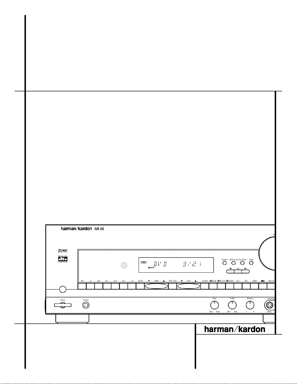
5 FRONT-PANEL CONTROLS
1 Main Power Switch: Press this button to
apply power to the AVR 300. When the switch
is pressed in,the unit is placed in a Standby
m o d e, as indicated by the amber LED 3 s u rrounding the System Po w e r C o n t ro l 2.
This button MUST be pressed in to operate the
u n i t .To turn the unit off and prevent the use
of the remote control, this switch should be
pressed until it pops out from the front panel
so that the word “ O F F ” may be read at the
top of the switch.
NOTE:In normal operation this switch is left in
the “ON”position.
2 System Power Control: When the Main
Power Switch1is “ON,” press this button
to turn on the AVR 300;press it again to turn
the unit off.Note that the Power Indicator
surrounding the switch 3will turn green
when the unit is on.
3 Power Indicator: This LED will illuminate
in amber when the unit is in the Standby mode
to signal that the unit is ready to be turned on.
When the unit is in operation,the indicator will
turn green.
4 Headphone Ja c k :This jack may be used to
listen to the AVR 300’s output through a pair of
h e a d p h o n e s.Be certain that the headphones
have a standard 1/4" stereo phone plug.N o t e
that the main room speakers will automatically
be turned off when the headphone jack is in use.
5 Bass Contro l :Turn this control to modify the
low-frequency output of the left/right channels by
as much as ±10dB.Set this control to a suitable
position for your taste or room acoustics.
6 Treble Contro l :Turn this control to modify
the high-frequency output of the left/right chan-
nels by as much as ±10dB.Set this control to a
suitable position for your taste or room acoustics.
7 Balance Control: Turn this control to
change the relative volume for the front
left/right channels.
NOTE: For proper operation of the surround
modes this control should be at the midpoint
or “12 o’clock”position.
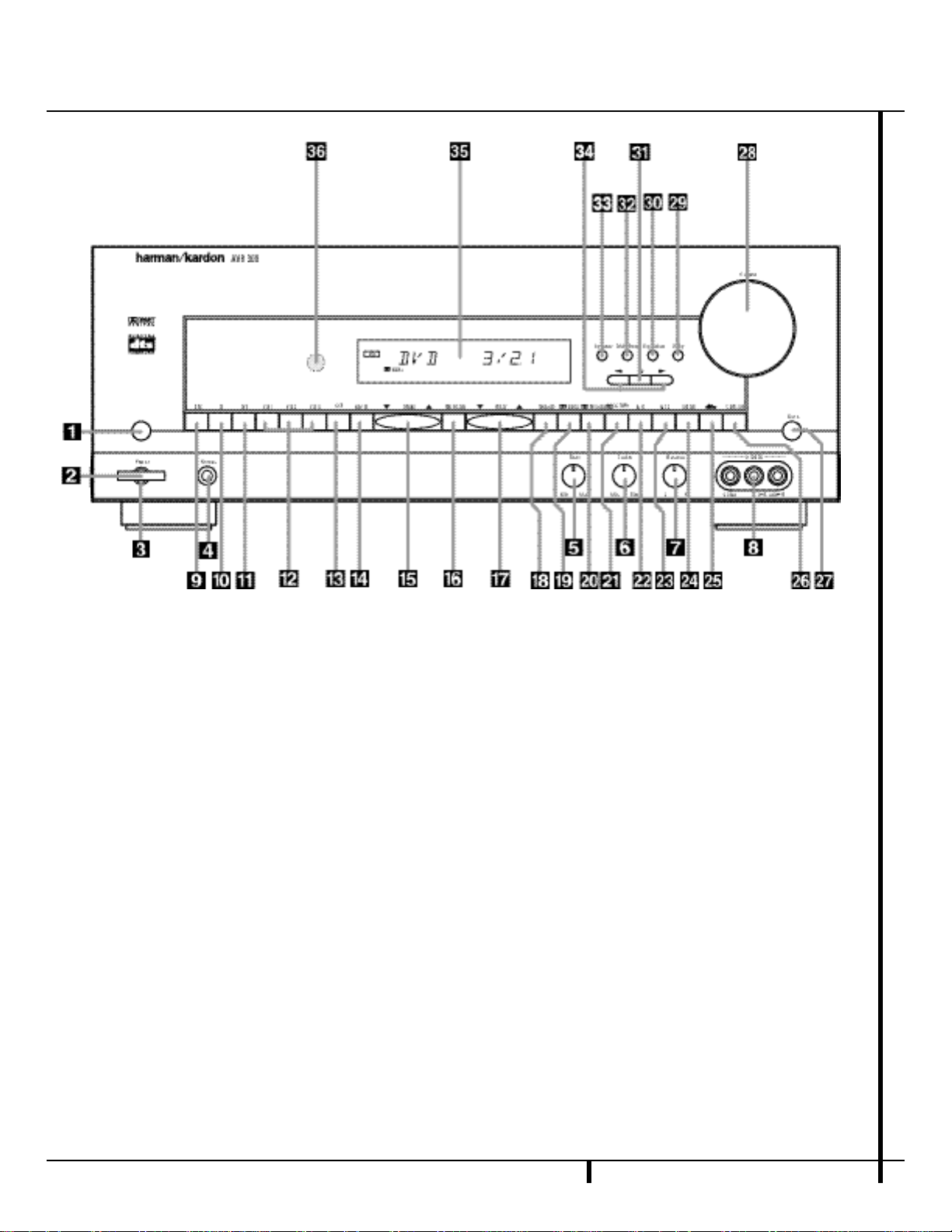
Front-Panel Controls
1 Main Power Switch
2 System Power Control
3 Power Indicator
4 Headphone Jack
5 Bass Control
6 Treble Control
7 Balance Control
8 Video 3 Inputs
9 Tape Selector
) CD Input Selector
! DVD Input Selector
@ Video Input Selectors
# 6-Channel Direct Selector
$ AM/FM Selector
% Tuning Button
^ Preset Scan
& Preset Stations Selector
* Tuner Mode
( Dolby Digital Selector
Ó Dolby Pro Logic Selector
Ô Dolby 3 Stereo Selector
Hall 1 Selector
Ò Hall 2 Selector
Ú Theater Mode Selector
Û DTS Selector
Ù Surround Off
ı Mute
ˆ Volume Control
˜ Delay
¯ Digital Input Selector
˘ Set Button
¸ Multiroom Selector
3 3
Speaker Select Button
3 4
Selector Buttons
3 5
Information Display
36
Remote Sensor
Page 7

6 FRONT-PANEL CONTROLS
Front-Panel Controls
8 Video 3 Inputs: These audio/video inputs
may be used for temporary connection of video
games,camcorders, digital still cameras or
portable audio products. To select a source
connected to these jacks, press the Vid 3
Input Selector @.
9 Tape Selector: Press this button to select
the device connected to the Tape In jacks f
as the listening source.
) CD: Press this button to select the device
connected to the CD Input jacks ¶ as the
listening source.
! DVD Input Selector: Press this button to
select the device connected to the DVD Input
jacks ∞ as the listening and viewing source.
@ Video Input Selectors: Press one of
these buttons to select a source connected to
the rear panel Video inputs ¡ a,or the front
panel Video 3 input 8.
# 6-Channel Direct Selector: Press this
button to select the output of an optional,
external 6-channel decoder connected to the
6-Ch Direct inputs § as the listening source.
$ AM/FM: Press this button to select the
tuner as the AVR 300’s input source.When it
is first pressed the last station tuned will be
heard. Press it again to change between AM
and FM bands.
% Tuning Button: Press the left side of the
button to tune lower frequency stations and the
right side of the button to tune higher frequency
stations.When a station with a strong signal is
reached, the TUNED indicator T will illuminate in the Information Display
3 5
.
To tune manually,tap the button lightly and
note that the tuner will step up one frequency
per button press.When the button is held for a
few seconds you will note that the unit will
quickly search the frequency band.Release it
once the fast tuning starts and the tuner will
automatically scan for the next station with an
acceptable signal and then stop.
^ P reset Scan: Press this button to automat-
ically scan through the stations that have been
p r o g rammed in the AVR 300’s memory.Th e
tuner will play five seconds of each station
before moving to the next preset station.To
stop the scan when the desired station is heard,
press the button again.(See pages 24–25 for
more information on the tuner memory system.)
& Preset Stations Selector: Press this but-
ton to select stations that have been entered
into the preset memory. (See pages 24–25 for
more information on tuner programming.)
* Tuner Mode: Press this button to select
the stereo or mono mode for FM tuning.In the
STEREO mode a Stereo indicator S will illuminate in the information display, and stereo
reception will be provided when stations are
transmitting stereo signals.In the MONO mode
the left and right signals from stereo broadcasts
will be mixed together.Select MONO for better
reception of weak signals.
( Dolby Digital Selector:Press this button to
select the Dolby Digital surround mode when listening to a program that carries Dolby Digital
i n f o r m a t i o n .(See pages 21–24 for more information on surround modes and digital audio. )
Ó Dolby Pro Logic Selector: Press this
button to select the Dolby Pro Logic surround
mode when listening to an analog program
that is encoded with surround-sound information.(See page 21–23 for more information on
surround modes.)
Ô Dolby 3 Stereo Selector: Press this but-
ton to select the Dolby 3 Stereo listening mode.
This mode is used primarily when a center
channel speaker but no surround speakers, are
installed.(See pages 22 for more information
on surround modes.)
Hall 1 Mode Selector: Press this button
to activate the Hall 1 mode as an alternative
surround mode when stereo sources are in
u s e.This mode provides the reverbera n t
atmosphere of a medium-sized concert hall.
Ò Hall 2 Mode Selector: Press this button
to activate the Hall 2 mode as an alternative
surround mode when stereo sources are in
u s e.This mode provides the reverbera n t
atmosphere of a large concert hall.
Ú Theater Mode Selector: Press this button
to activate the Theater mode as an alternate
surround mode when stereo sources are in use.
Û DTS Selector: Press this button to select
DTS decoding when listening to an audio or
video program that is encoded in the DTS form a t . (See pages 22–24 for more information on
surround modes and digital audio. )
Ù Surround Off: Press this button to turn off
all surround processing and to listen to a program in traditional stereo from the left front
and right front speakers only.
ı
Mute: Press this button to momentarily
silence the speaker and headphone outputs of
the AVR 300.
ˆ Volume Control: Turn the knob clockwise
to increase volume, counterclockwise to
decrease the volume. If the AVR is muted,
adjusting volume control will automatically
release the unit from the silenced condition.
˜ Delay: Press this button to begin the
sequence of steps required to enter delay time
settings.(See pages 18–19 for more information on delay times.)
¯ Digital Input Selector: When playing a
source that has a digital output,press this
button to select between the Optical d and
Coaxial e Digital inputs.(See pages 23–24
for more information on digital audio.)
˘ Set Button:When making choices during
the setup and configuration process,press this
button to enter the desired setting as shown
in the Information Display
3 5
,,into the
AVR 300’s memory.
¸ Multiroom Selector: Press this button
to activate the AVR 300’s Multiroom system.
(See page 26 for complete information on
Multiroom operation.)
3 3
Speaker Select Button: Press this button
to begin the process of selecting the speaker
positions that are used in your listening room.
(See page 16 for more information on setup
and configuration.)
3 4
Selector Buttons:When you are establishing the AVR 300’s configuration settings, u s e
these buttons to select between the choices ava i la b l e,as shown in the Information Display
3 5
,.
3 5
Information Display: This display delivers messages and status indications to help you
operate the receiver.(See page 7 for a complete
explanation of the Information Display.)
3 6
Remote Sensor Window:The sensor
behind this window receives infrared signals
from the remote control.Aim the remote at this
area and do not block or cover it unless an
external remote sensor is installed.
Page 8
7 FRONT-PANEL INFORMATION DISPLAY
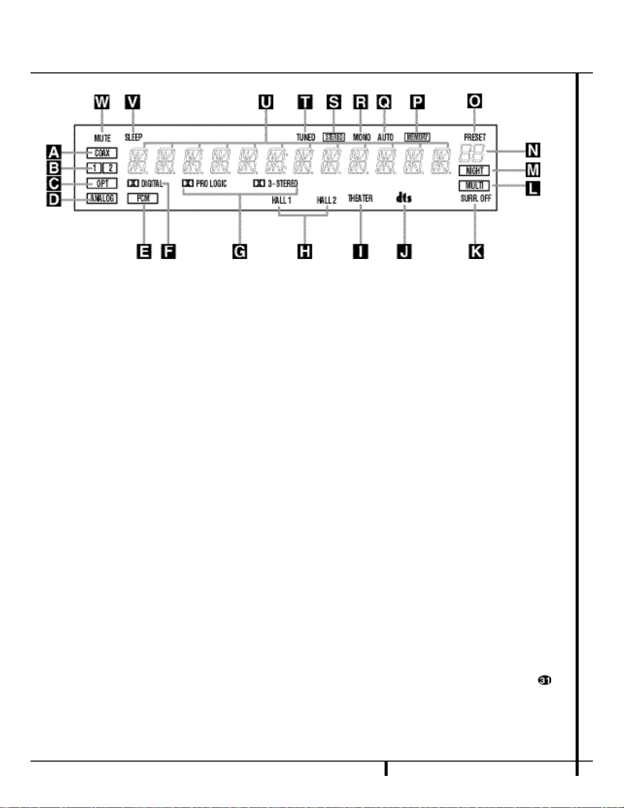
Front-Panel Information Display
A Coax Source
B Digital Source Input Number
C Optical Source
D Analog Source Indicator
E PCM Indicator
F Dolby Digital Indicator
G Analog Dolby Surround Mode Indicators
H Hall Mode Indicators
A Coax Source: This indicator illuminates
when a digital source is in use via a connection
to the Coaxial Digital inputs e.
B Digital Source Input Number:Th e s e
indicators tell you which of the two digital
inputs is selected.This indicator works in conjunction with the Coax Source A a n d
Optical Source C indicators to show which
form of digital signal is in use.
C Optical Source: This indicator illuminates
when a digital source is in use via a connection
to the Optical Digital input d.
D Analog Source Indictor: This indicator
illuminates when an analog input source is in use.
E PCM Indicator:This indicator illuminates
to show that a standard PCM (S/P-DIF) digital
audio signal is being decoded by the digital-toanalog converter.
F Dolby Digital Indicator: This indicator
illuminates when a Dolby Digital source is
being played.
G Analog Dolby Surround Mode
Indicators: These indicators illuminate when
one of the analog (matrix) Dolby Surround
modes is in use.
H Hall Mode Indicators : One of these indi-
cators illuminate when either of the Hall modes
are in use.
I Theater Mode Indicator
J DTS Mode Indicator
K Surround Off
L Multiroom System Indicator
M Night Mode Indicator
N Preset Number
O Preset Indicator
P Memory
I Theater Mode Indicator:This indicator illu-
minates to show that the Theater mode is in use.
J DTS Mode Indicator:This indicator illumi-
nates when a DTS-encoded source is playing.
K Surround Off: This indicator illuminates
when the surround processing has been disabled by pressing the S u r round Off b u t t o n
Ù.When this indicator is lit, the AVR 300 will
play traditional stereo sound using the front-left
and front-right speakers only.
L M u l t i room System Indicator:This indica-
tor illuminates when the multiroom system is in
o p e ra t i o n . (See page 26 for more information
on the multiroom system.)
M Night Mode Indicator: This indicator
lights when the AVR 300 is in the Night mode,
which preserves the dynamic range of digital
p r o g ram material at low volume levels.
N Preset Number: This two-digit display
indicates the station preset number that is
currently in use, or that is being entered.
O P reset Indicator:This indicator illuminates
when a station previously entered into the preset
memory is tuned.The number that appears below
the indicator is the preset station’s memory.
P Memory: This indicator flashes when
entering presetsand other information into the
tuner’smemory.
Q Auto
R Mono Indicator
S Stereo Indicator
T Tuned Indicator
U Main Information Display
V Sleep Indicator
W Mute
Q Auto:This indicator illuminates when the
Auto mode is in use for FM tuning.
R Mono Indicator:This indicator illuminates
when the tuner has been placed in the monaura l
mode by pressing the Tune Mode button *.
Set the tuner for mono listening to reduce noise
and improve the quality of distant stereo signals.
S S t e reo Indicator:This indicator illuminates
when an FM station is being tuned in stereo.
T Tuned Indicator:This indicator illuminates
when a station is being received with sufficient signal strength to provide acceptable listening quality.
U Main Information Display: This display
shows messages relating to the status,input
source,surround mode, tuner,volume level or
other aspects of unit’s operation.
V Sleep Indicator: This indicator is illumi-
nated when the Sleep function is in use.The
number that appears above the indicator is
the number of minutes remaining before the
AVR 300 will return to the Standby mode.
W Mute: This indicator illuminates to remind
you that the AVR 300’s output has been
silenced by pressing the M u t e button ı .
Press the Mute button again to return to the
previously selected output level.
Page 9
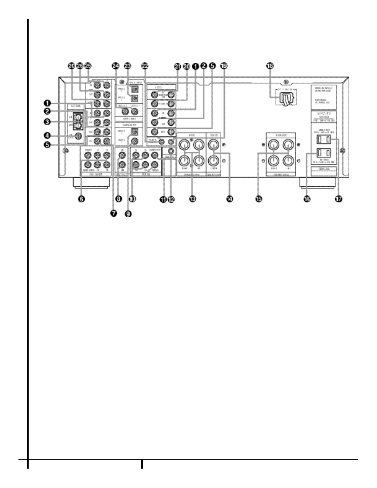
8 REAR-PANEL CONNECTIONS
Rear-Panel Connections
¡ Video 1 Inputs
™ Video 1 Outputs
£ AM Antenna
¢ FM Antenna
∞ DVD Inputs
§ 6-Channel Direct Inputs
¶ CD Inputs
• Multiroom Audio Outputs
ª Digital Outputs
NOTE:For all video source inputs and outputs
¡ ™ ∞ a, the same number is used to
indicate the audio, composite-video and S-Video
connections related to that input. This accounts
for the same number appearing in more than
one place on the rear-panel drawing.
‚ Preamp Outputs
⁄ Subwoofer Output
¤ Multiroom IR Input
‹ Front-Speaker Terminals
› Center-Speaker Terminals
fi Surround-Speaker Terminals
fl Switched AC Outlet
‡ Unswitched AC Outlet
° AC Power Cord
· Remote IR Input
a Video 2 Inputs
b TV Monitor Video Outputs
c Remote IR Output
d Optical Digital Inputs
e Coaxial Digital Inputs
f Tape Inputs
g Tape Outputs
Page 10

9 REAR-PANEL CONNECTIONS
Rear-Panel Connections
¡ Video 1 Inputs: Connect these jacks to
the audio and video PLAY/OUT jacks of a VCR.
™ Video 1 Outputs: Connect these jacks to
the audio and video RECORD/IN jacks of a VCR.
£ A MA n t e n n a :C o n n e c tt h eA Ml o o pa n t e n n a
s u p p l i e dw i t ht h er e c e i v e rt ot h e s et e r m i n a l s.I fa n
e x t e r n a lA Ma n t e n n ai su s e d ,m a kec o n n e c t i o n s
to the AM andGND terminals in accordance
withthe instructions supplied with the antenna.
¢ FM A n t e n n a :Connect the supplied indoor or
the optional external FM antenna to this terminal.
∞ DVD Inputs: Connect the analog audio
outputs and composite video output of a DVD
or LD player to these jacks.
§ 6-Channel Direct Inputs: If an external
digital audio decoder is used,connect the outputs of that decoder to these jacks.
¶ CD Inputs: Connect these jacks to the out-
put of a compact disc player or CD changer.
• Multiroom Audio Outputs: Connect
these jacks to the inputs of an optional audio
power amplifier so that the input selected by
the multiroom control system will be heard in a
remote room.
ª Digital Audio Outputs: Connect these
jacks to the matching digital input connector
on a digital recorder such as a CD-R or
MiniDisc recorder.
‚ Preamp Outputs: If external power ampli-
fiers are used for any channels,connect them to
these jacks.
⁄ Subwoofer Output: Connect this jack to
the line-level input of a powered subwoofer. If
an external subwoofer amplifier is used,connect this jack to the subwoofer amplifier input.
¤ M u l t i room IR Input:Connect the output
of an IR sensor in a remote room to this jack to
o p e rate the AVR 300’s multiroom control system.
‹ Front-Speaker Teminals: Connect the
front left/right speakers to these terminals.
› Center-Speaker Terminals: Connect the
center speaker to these terminals.
fi Surround-Speaker Terminals: Connect
the surround speakers to these terminals.
NOTE:When making connections to the
Speaker Terminals ‹ › fi always be certain
to maintain correct polarity between the speaker’s terminals and those on the AVR by connecting red (+) termianls to red and black (–)
terminals to black.(See page 13 for more information on speaker polarity.)
fl Switched AC Outlet: This outlet may be
used to power any device that you wish to have
turn on when the unit is turned on with the
System Power Control switch 2.
‡ Unswitched AC Outlet: This outlet may
be used to power any AC device.The power will
remain on at this outlet regardless of whether
the AVR 300 is on or off.
NOTE:The power consumption of the device
plugged into each of these outlets fl‡
should not exceed 100 watts.
° AC Power Cord: Connect the AC plug to a
nonswitched AC wall output.
· Remote IR Input: If the AVR 300’s front-
panel IR sensor is blocked due to cabinet
doors or other obstructions, an external IR
sensor may be used. Connect the output of
the sensor to this jack.
a Video 2 Inputs: Connect these jacks to
the audio and video outputs of a TV Tuner,
Cable TV converter box,satellite receiver or any
other audio/video source.
b TV Monitor Video Output: Connect this
jack to the composite or S-Video input of a T V
monitor or video projector to view the on-screen
menus and the output of any standard video
source selected by the receiver’s video switcher.
c Remote IR Output: This connection per-
mits the IR sensor in the receiver to serve other
remote controlled devices. Connect this jack to
the “IR IN”jack on Harman Kardon or other
compatible equipment.
d Optical Digital Inputs: Connect the opti-
cal digital output from a DVD player, HDTV
receiver,LD player or CD player to these jacks.
The signal may be either a Dolby Digital signal,
a DTS signal or a standard PCM digital source.
e Coaxial Digital Inputs: Connect the coax
digital output from a DVD player, HDTV receiver,
LD player or CD player to these jacks. The signal
may be either a Dolby Digital signal,DTS signal
or a standard PCM digital source.
f Tape Inputs: Connect these jacks to the
PLAY/OUT jacks of an audio recorder.
g Tape Outputs: Connect these jacks to the
RECORD/INPUT jacks of an audio recorder.
Page 11
●
●
●
●
●
●
●
●
10 REMOTE CONTROL FUNCTIONS
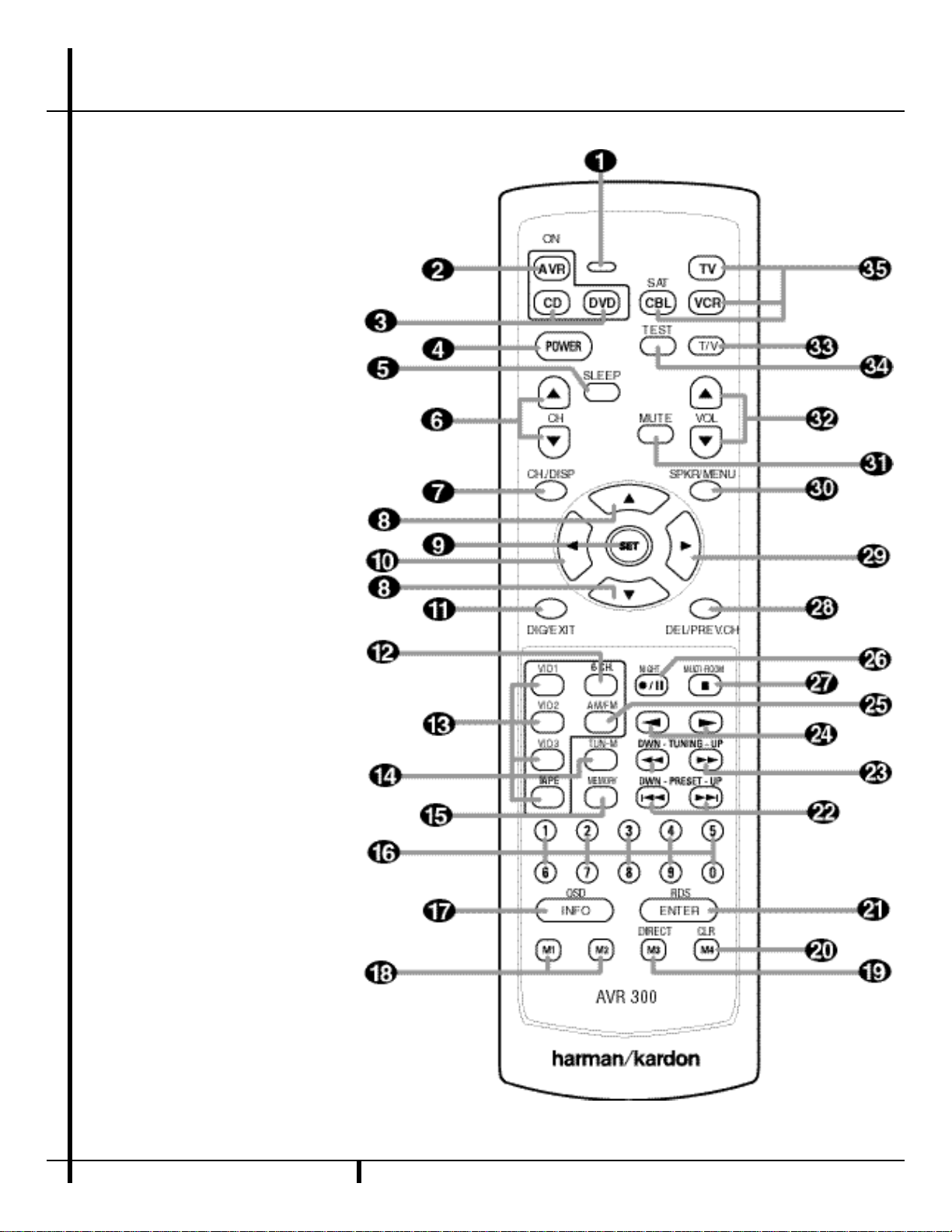
Remote Control Functions
a Command Indicator
b AVR Selector
c CD/Tape/DVD Input Selectors
d Power-Off Button
e Sleep Button
f Surround Mode/TV Channel Selectors
g Channel-Select Button
⁄/¤
h
i Set Button
j
k Digital Select/Exit
l 6-Ch.Direct Input
m Input Selector Buttons
n Tuner Mode
o Memory Button
p Numeric Keys
q OSD/Info Button
r Macro 1/2 Buttons
s Direct/Macro 3 Button
t Clear/Macro 4 Button
u Enter Button
v Preset Up/Down
w Tuning Up/Down
x Forward/Reverse Transport Buttons
y AM/FM Tuner Select
z Night Mode
` Multiroom
28
29
30
31
32
33
34
35
Buttons
‹
Button
Delay
›
Button
Speaker Select
Mute
Volume Up/Down
TV/VCR Button
Test Tone
Video Device Selectors
NOTE:The function names shown here are each
button’s feature when used with the AVR.Most
buttons have additional functions when used
with other devices. See page 30 for a list of
these functions.
Page 12

11 REMOTE CONTROL FUNCTIONS
Remote Control Functions
I M P O RTANT NOT E :The AVR 300’s remote may
be programmed to control up to eight devices,
including the AVR 300.Before using the remote,
it is important to remember to press the D e v i c e
C o n t rol Selector button b c t h a t
corresponds to the unit you wish to opera t e.I n
a d d i t i o n , the AVR 300’s remote is shipped from
the factory to operate the AVR 300 and most
Harman Kardon CD or DVD players and cassette
d e c k s.The remote is also capable of operating a
wide variety of other products using the control
codes that are part of the remote.Before using
the remote with other products, follow the
instructions on pages 27–29 to program the
proper codes for the products in your system.
It is also important to remember that many of
the buttons on the remote take on different
functions,depending on the product selected
using the Device Control Selectors. The descriptions shown here primarily detail the functions
of the remote when it is used to operate the
AVR 300. (See page 29 for information about
alternate functions for the remote’s buttons.)
a Command Indicator: This LED lights
briefly when a button is pushed to confirm that an
i n f ra-red (IR) commande is being sent by the
r e m o t e.
b AVR Selector: Pressing this button will
switch the remote so that it will operate the
AV R ’s functions.If the AVR is in the Standby
m o d e,it will also turn the AVR on.
c CD/DVD Input Selectors: Pressing one
of these buttons will perform three actions at
the same time. First,if the AVR is not turned on,
this will power up the unit.Next, it will select
the source shown on the button as the input to
the AVR.Finally,it will change the remote control so that it controls the device selected.After
pressing one of these buttons you must press
the AVR Button b again to operate the
AVR’s functions with the remote.
d Power-Off Button: Press this button to
place the unit in the Standby mode. Note that
this will turn off the main room functions,but
if the Multiroom system is activa t e d ,it will
continue to function.
e Sleep Button: Press this button to place
the unit in the Sleep mode.After the time
shown in the display, the AVR 300 will automatically go into the Standby mode.Each press
of the button changes the time until turn-off in
the following order:
Press and hold the button for two seconds to
turn off the Sleep mode setting.
Note that this button is also used to change
channels on your TV when the TV is selected
using the Device Control Selectors
c .
f Surround Mode/TV Channel
Selectors:Press this button to begin the
process of changing the Surround mode.After
the button has been pressed,use the
⁄/¤
but-
tons h to select the desired surround mode.
(See page 21 for more information.) Note that
this button is also used to tune channels when
the TV is selected using the Device Control
Selector . When the AVR 300 remote is
being programmed for the codes of another
device,this button is also used in the “Auto
Search” process.(See page 27 for more infor-
mation on programming the remote.)
g Channel-Select Button: This button is
used to start the process of setting the AVR 300’s
output levels to an external source.Once this
button is pressed,use the
⁄/¤
b u t t o n s h t o
select the channel being adjusted,then press the
S e t button i,followed by the
⁄/¤
b u t t o n s
a g a i n ,to change the level setting.(See page 25
for more information.)
h
⁄/¤
Buttons:These are multipurpose
butt o n s.They will be used most frequently to
select a surround mode.To change the surround
m o d e,first press the SURR/CH ¤b u t t on f
Next press these buttons to scroll up or down
through the list of surround modes that appear in
the Information Display
3 5
..These buttons are
also used to increase or decrease output levels
when configuring the unit with either the internal test tone or an external source.They are
also used to enter delay time settings after the
Delay button has been pressed.
i Set Button:This button is used to enter
settings into the AVR 300’s memory.It is also
used in the setup procedures for delay time,
speaker configuration and channel output level
adjustment.
j
‹
B u t t o n :This button is used to change
the menu selection or setting during some of
the setup procedures for the AV R .
k Digital Select: Press this button to assign
one of the digital inputs d e to a source.
(See page 23 for more information on using
digital inputs.)
l 6 - C h . D i rect Inputs: Press this button to
select the component connected to the 6-Ch.
direct Input § as the source
m Input Selectors :Press one of these but-
tons to select one of the video inputs or the
tape input as the source for the AV R .P r e s s i n g
one of these buttons when the AVR 300 is in
the Standby mode will also turn the unit on.
n Tuner Mode: Press this button when the
tuner is in use to select between automatic
tuning and manual tuning.When the button is
pressed so that the AUTO indicator Q goes
out, pressing the Tuning buttons w will
move the frequency up or down in single-step
increments.When the FM band is in use, pressing this button when a station’s signal is weak
will change to monaural reception,as indicated
by the MONO indicator R.(See page 24 for
more information.)
o Memory Button:Press this button to enter
a radio station into the AVR 300’s preset memory.
After pressing the button the M E M O RY i n d i c a t o r
P will flash; you then have five seconds to
enter a present memory location using the
Numeric Keys p. (See pages 24–25 for
more information.)
p Numeric Ke y s :These buttons serve as a
ten-button numeric keypad to enter tuner preset
p o s i t i o n s.They are also used to select channel
numbers when TV has been selected on the
remote,or to select track numbers on a CD,
DVD or LD player,depending on how the
remote has been programmed.
q OSD Button: Press this button to view the
on-screen displays.
r M a c ro 1–2 Buttons:These buttons are
used to recall or enter the progra m m i n g
sequence for a preprogrammed Macro
s e q u e n c e.(See page 28 for more information
on programming and using Macros. )
s Direct/Macro 3 Button: This button has
two functions. Pressing it when the tuner is in
use will start the sequence for direct entry of a
station’s frequency.After pressing the button
simply press the proper Numeric Keys p to
select a station. This button may also be used to
store or recall a macro sequence. (See pages
24–25 for more information on the tuner, and
page 28 for more information on programming
and using Macros.)
Page 13

12 REMOTE CONTROL FUNCTIONS
Remote Control Functions
t C l e a r / M a c ro 4 Button:This button may
be used to store and recall a macro; it may also
be programmed for use with other devices. ( S e e
page 28 for nore information on macros. )
u Enter Button: This button does not have
a function on the AV R ,but it can transmit the
“ E n t e r ” command when the remote is pro-
g rammed for use with other products. ( S e e
pages 27–29 for more information.)
v Preset Up/Down: When the tuner is in
use,these buttons scroll through the stations
that have been programmed into the AVR 300’s
memory.When some source devices, such as
CD players,VCRs and cassette decks,are
selected using the Device Control Selectors
c , these buttons will normally function
as chapter step or track advance.
w Tuning Up/Down:When the tuner is in
u s e,these buttons will tune up or down through
the selected frequency band.If the Tuner Mode
button n has been pressed so that the AU TO
indicator Q is illuminated, pressing and holding
the buttons for three seconds will cause the
tuner to seek the next station with acceptable
signal strength for quality reception.When the
AU TO indicator Q is NOT illuminated,p r e s s i n g
these buttons will tune stations in single-step
i n c r e m e n t s.(See page 24 for more information.)
x Forward/Reverse Transport Buttons:
These buttons do not have any functions for
the AVR, but they may be programmed for the
forward/reverse play operation of a wide variety
of CD or DVD players, and audio or videocassette recorders. (See page 27 for more
information on programming the remote.)
y AM/FM Tuner Select: Press this button to
select this AVR’s tuner as the listening choice.
Pressing this button when a tuner is in use will
select between the AM and FM bands.
z Night Mode: Press this button to activate
the Night mode.This mode is available in specially encoded digital sources, and it preserves
dialog (center channel) intelligibility at low
volume levels.
` M u l t i ro o m : Press this button to activate
the Multiroom system or to begin the process
of changing the input or volume level for the
second zone.(See page 26 for more information
on the Multiroom system.)
Delay/Prev Ch.: Press this button to
begin the process for setting the delay times
used by the AVR 300 when processing surround
sound.After pressing this button,the delay
times are entered by pressing the Set button
i and then using the
⁄/¤
buttons h to
change the setting. Press the Set button again
to complete the process. (See page 18–19 for
more information.)
›
Button: Press this button to change a
setting or selection when configuring many of the
AV R ’s settings.
S p e a ker Select: Press this button to
begin the process of configuring the AVR 300’s
Bass Management System for use with the type
of speakers used in your system.Once the button
has been pressed,use the
⁄/¤
buttons h t o
select the channel you wish to set up.Press the
S e t button i and then select another channel
to configure.When all adjustments have been
c o m p l e t e d , press the Set button twice to exit the
settings and return to normal opera t i o n .( S e e
page 16 for more information.)
Mute: Press this button to momentarily
silence the AVR 300 or TV set being controlled,
depending on which device has been selected.
When the AVR 300 remote is being progra m m e d
to operate another device,this button is pressed
with the Device Control Selector button
to begin the programming process. (See
page 27 for more information on programming
the remote.)
Volume Up/Down: Press these buttons
to raise or lower the system volume.
TV/VCR Button:This button does not
have a control function for the AVR 300,but it
is available for use with other devices.When
the remote is controlling a VCR,it will typically
perform the TV/VCR switch function.(See pages
27–29 for more information on using the
remote with other products.)
Test Tone: Press this button to begin the
sequence used to calibrate the AVR 300’s output
l e v e l s. (See pages 17–18 for more information
on calibrating the AVR 300.)
Video Remote Selectors :Press one of
these buttons to use the remote to control the
functions of the device shown on the button.( Fo r
more information on programming the remote to
o p e rate these devices,see pages 27–29.
NOTE:As any of these buttons is pressed,it
will briefly flash red to confirm your selection.
Page 14

System Installation
After unpacking the unit,and placing it on a solid
surface capable of supporting its weight,you will
need to make the connections to your audio and
video equipment.
Audio Equipment Connections
We recommend that you use high-quality interconnect cables when making connections to
source equipment and recorders to preserve the
integrity of the signals.
When making connections to audio source
equipment or speakers it is always a good practice to unplug the unit from the AC wall outlet.
This prevents any possibility of accidentally
sending audio or transient signals to the speakers that may damage them.
1.Connect the analog output of a CD player to
the CD inputs ¶.
NOTE:When the CD player has both fixed and
variable audio outputs it is best to use the fixed
output unless you find that the input to the
receiver is so low that the sound is noisy,or so
high that the signal is distorted.
2.Connect the analog Play/Out jacks of a cassette deck,MD,CD-R or other audio recorder to
the Tape In jacks f. Connect the analog
Record/In jacks on the recorder to the Tape
Out jacks g on the AVR 300.
3 . Connect the output of any digital sources
to the appropriate input connections on the
AVR 300 rear panel.Note that the O p t i c a l
and C o a x i a l digital inputs d e may be
used with a Dolby Digital or DTS source or
the output of a conventional CD or LD player’s
PCM (S/P-DIF) output.
4 .Connect the Coax or Digital Outputs ª o n
the rear panel of the AVR to the matching digital
input connections on a CD-R or MiniDisc recorder.
5.Assemble the AM Loop Antenna supplied
with the unit as shown below.Connect it to the
AM and GND screw terminals £.
6.Connect the supplied FM antenna to the FM
(75 ohm) connection ¢. The FM antenna may
be an external roof antenna, an inside powered
or wire lead antenna or a connection from a
cable TV system. Note that if the antenna or
connection uses 300-ohm twin-lead cable, you
must use the 300-ohm-to-75-ohm adapter
supplied with the unit to make the connection.
7.Connect the front, center and surround
speaker outputs ‹ › fi to the respective
speakers.
To assure that all the audio signals are carried
to your speakers without loss of clarity or resolution, we suggest that you use high-quality
speaker cable.Many brands of cable are available and the choice of cable may be influenced
by the distance between your speakers and the
receiver,the type of speakers you use,personal
preferences and other factors.Your dealer or
installer is a valuable resource to consult in
selecting the proper cable.
Regardless of the brand of cable selected, w e
recommend that you use a cable constructed of
f i n e,m u l t i s t rand copper with a gauge of 14 or
s m a l l e r. Remember that in specifying cable,t h e
lower the number,the thicker the cable.
Cable with a gauge of 16 may be used for short
runs of less than ten feet.We do not recommend that you use cables with an AWG equivalent of 18 or higher due to the power loss and
d e g radation in performance that will occur.
Cables that are run inside walls should have the
appropriate markings to indicate listing with UL,
CSA or other appropriate testing agency stand a r d s.Questions about running cables inside
walls should be referred to your installer or a
licensed electrical contractor who is familiar
with the NEC and/or the applicable local building codes in your area.
When connecting wires to the speakers, be certain to observe proper polarity. Remember to
connect the “negative”or “black”wire to the
same terminal on both the receiver and the
speaker.Similarly, the “positive”or “red”wire
should be connected to like terminals on the
AVR 300 and speaker.
We also recommend that the length of cable
used to connect speaker pairs be identical.
For example, use the same length piece of
cable to connect the front-left and front-right
or surround-left and surround-right speake r s,
even if the speakers are a different distance
from the AVR 300.
NOTE:While most speaker manufacturers
adhere to an industry convention of using black
terminals for negative and red ones for positive,
some manufacturers may vary from this configuration.To assure proper phase and optimal
performance, consult the identification plate on
your speaker or the speaker’s manual to verify
polarity.If you do not know the polarity of your
speaker,ask your dealer for advice before proceeding,or consult the speaker’s manufacturer.
8.Connections to a subwoofer are normally
made via a line level audio connection from the
Subwoofer Output ⁄ to the line-level input
of a subwoofer with a built-in amplifier.When a
passive subwoofer is used, the connection first
goes to a power amplifier, which will be connected to one or more subwoofer speakers. If
you are using a powered subwoofer that does
not have line-level input connections, follow the
instructions furnished with the speaker for connection information.
Video Equipment Connections
Video equipment is connected in the same manner as audio components.A g a i n , the use of highquality interconnect cables is recommended to
preserve signal quality.
1.Connect a VCR’s audio and video Play/Out
jacks to the Video 1 In jacks ¡ on the rear
panel.The audio and Record/In jacks on the
VCR should be connected to the Video 1 Out
jacks ™ on the AVR 300.
2.Connect the analog audio and video outputs
of a satellite receiver,cable TV converter or
television set or any other video source to the
Video 2 In jacks a.
3 . Connect the analog audio and video
outputs of a DVD or laser disc player to the
DV D jacks ∞.
4.Connect the digital audio outputs of a DVD
player, satellite receiver, cable box or HDTV converter to the appropriate Optical or Coaxial
Digital Inputs d e.
5.Connect the TV Monitor Out b jacks on
the receiver to the composite or S-Video input
of your television monitor or video projector.
13 INSTALLATION AND CONNECTIONS
Installation and Connections
Page 15

14 INSTALLATION AND CONNECTIONS
Installation and Connections
NOTE:The AVR 300 will accept both standard
(composite) or S-Video signals. However,it will
not convert signals from one video format type
to the other.
System and Power Connections
The AVR 300 is designed for flexible use with
multiroom systems, external control compo-
nents and power amplifiers.
Main Room Remote Control Extension
If the receiver is placed behind a solid or
smoked glass cabinet door,the obstruction may
prevent the remote sensor from receiving commands. In this event,an optional remote sensor
may be used. Connect the output of the remote
sensor to the Remote Cont. In jack ·.
If other components are also prevented from
receiving remote commands, only one sensor is
needed.Simply use this unit’s sensor or a
remote eye by running a connection from the
Remote IR Output jack c to the Remote In
jack on Harman Kardon or other compatible
equipment.
Multiroom IR Link
The remote room IR receiver should be connected
to the AVR 300 via standard coaxial cable.P l u g
the IR connection cable into the M u l t i ro o mj a c k
¤ on the AVR 300’s rear panel.
If other Harman Kardon compatible source
equipment is part of the main room installation,
the Remote IR Output jack c on the rear
panel should be connected to IR IN jack on the
CD player or cassette deck.This will enable the
remote room location to control source equip-
ment functions in addition to the remote room
input and volume.
NOTE:All remotely controlled components
must be linked together in a daisy chain.
Connect the IR OUT jack of one unit to the IR
IN of the next to establish this chain.
Multiroom Audio Connections
Depending on the distance from the AVR 300
to the remote room, two options (A and B)
are ava i l a b l e :
A. Use high-quality, shielded audio interconnect
cable from the AVR 300’s location to the
remote room.At the remote room,connect the
interconnect cable to a stereo power amplifier.
The amplifier will be connected to the room’s
speakers.No volume control is required,as the
AVR 300 and the remote IR link will provide
that function.At the AVR 300,plug the audio
interconnect cables into the Multi Out jacks
• on the AVR 300’s rear panel.
N OT E :The remote power amplifier must have
signal sensing capability or be left on constantly to
assure automatic operation at the remote room.
B.Place the amplifier that will provide power to
the remote location speakers in the same room
as the AVR 300,and connect the Multi Out
jacks • on the rear panel of the AVR to the
audio input of the remote room amplifier.Use
the appropriate speaker wire to connect the
optional power amplifier to the remote speake r s.
High-quality wire of at least AWG14 is recommended for long multiroom connections.
I M P O RTANT NOT E :A n y c a b l e s r u n i n s i d e wa l l s
s h o u l d b eC L 3 / F T 4 ra t e d ,o r c a r r ya n yo t h e rc e r t if i c a t i o n t h a ti s r e q u i r e d b yt h e NEC or s t a t e a n d
l o c a l b u i l d i n g a n de l e c t r i c a l c o d e s.Toa v o i di n t e rf e r e n c e,a u d i o a n d s p e a ke r c a b l e s s h o u l d n o t b e
p a ra l l e l t o,o r run in t h e s a m e c o n d u i t s or path
w i t h ,AC c a b l e s.I f y o u h a v e a n y q u e s t i o n sa b o u t
m u l t i r o o m w i r i n g ,c o n s u l ty o u r d e a l e r,c u s t o m
i n s t a l l e r o r a l i c e n s e dor low-voltage contra c t o r.
External Audio Power Amplifier
Connections
If desired,optional external power audio power
amplifiers may be used with the AVR 300.
Connections to these amplifiers are made by
using audio interconnect cables connected to
both the Preamp Outputs ‚ on the rear
panel and the audio input jacks of the external
amplifiers.
External Audio Decoder Connection
To provide for ultimate flexibility, the AVR 300
may be used in conjunction with optional,
external decoders for digital audio systems
other than the AVR 300’s own built-in Dolby
Digital and DTS decoding system.If an external
decoder is used,connect the output jacks of the
decoder to the 6-Channel Direct inputs §,
making sure to match channels.
These jacks may also be used for connections to
devices such as DVD players or High Definition
Television (HDTV) sets or decoders that feature
built-in digital surround decoders.Although the
digital decoding system in the AVR 300 will typically provide audio performance that is superior
to other decoders,you may use these jacks to
provide an additional 6-channel input for connec-
tion to a DVD player or HDTV set with a built-in
decoder and discrete 6-channel analog outputs.
AC Power Connections
This unit is equipped with two accessory AC
outlets.They may be used to power accessory
devices,but they should not be used with highcurrent draw equipment such as power amplifiers.The total power draw to each outlet may
not exceed 150 watts.
The Switched fl outlet will receive power
only when the unit is on.This is recommended
for devices that have no power switch or a
mechanical power switch that may be left in
the “ON”position.
N OT E : Many audio and video products go into
a Standby mode when they are used with
switched outlets, and cannot be fully turned on
using the outlet alone without a remote control
command.
The Unswitched ‡ outlet will receive power
as long as the unit is plugged into a powered
AC outlet.
Finally,when all connections are complete, plug
the power cord into a nonswitched120-volt AC
wall outlet.You’re almost ready to enjoy the
AVR 300!
Page 16
15 SYSTEM CONFIGURATION
System Configuration
When all audio,video and system connections
have been made,there are a few configura t i o n
adjustments that must be made.A few minutes
spent to correctly configure and calibrate the
unit will greatly add to your listening experience.
Speaker Selection and Placement
The placement of speakers in a multichannel
home-theater system can have a noticeable
impact on the quality of sound reproduced.
No matter which type or brand of speakers is
u s e d , the same model or brand of speake r
should be used for the front-left, center and
front-right speake r s.This creates a seamless
front soundstage and eliminates the possibility
of distracting sonic disturbances that occur
when a sound moves across mismatched
front-channel speake r s.
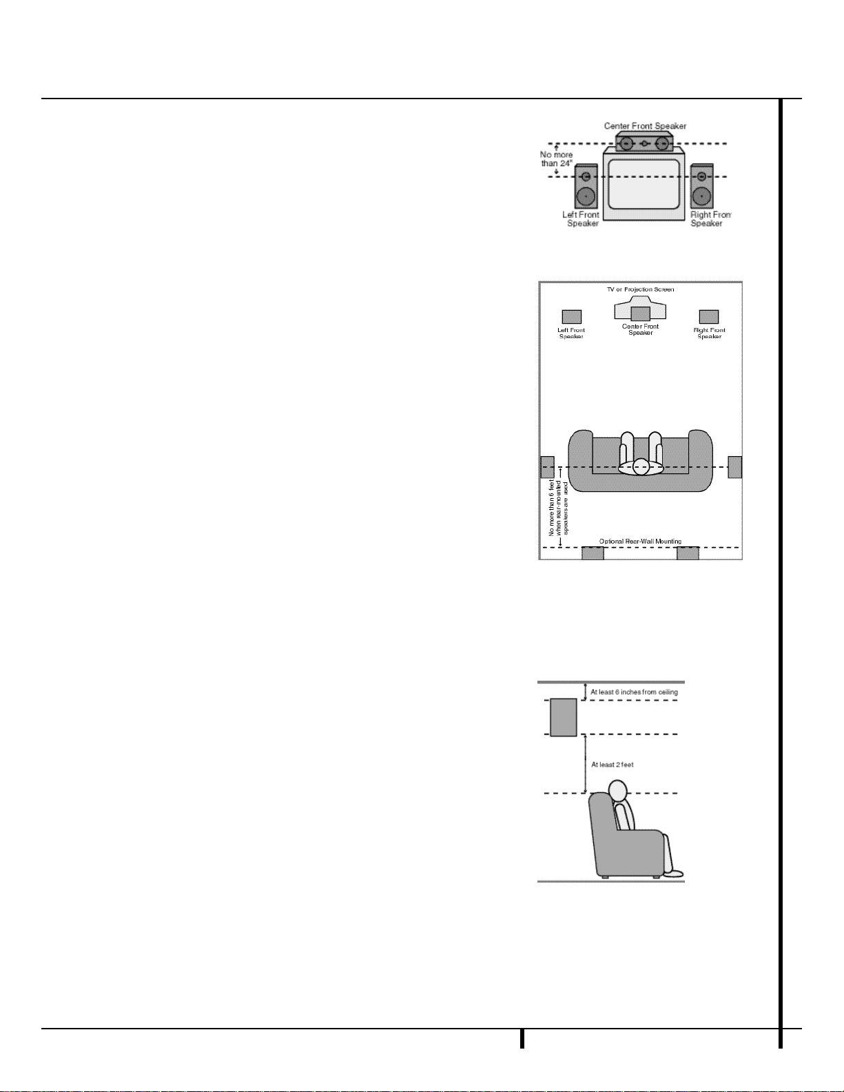
Speaker Placement
Depending on the type of center-channel
speaker in use and your viewing device,place
the center speaker either directly above or
below your TV, or in the center behind a perforated front-projection screen.
Once the center-channel speaker is installed,
position the left-front and right-front speakers
so that they are as far away from one another
as the center-channel speaker is from the preferred listening position.I d e a l l y,the front-channel
s p e a kers should be placed so that their tweeters
are no more than 24" above or below the
tweeter in the center-channel speaker.
Depending on the specifics of your room
acoustics and the type of speakers in use,y o u
may find that imaging is improved by moving
the front-left and front-right speakers slightly
f o r ward of the center-channel speake r. If possib l e, adjust all front loudspeakers so that they
are aimed at ear height when you are seated
in the listening position.
Using these guidelines,you’ll find that it take s
some experimentation to find the correct location for the front speakers in your particular
i n s t a l l a t i o n . Don’t be afraid to move things
around until the system sounds correct. O p t i m i z e
your speakers so that audio transitions across
the front of the room sound smooth,and that
sounds from all speakers appear to arrive at the
listening position at the same time (without
delay from the center speaker compared to the
left and right speake r s. )
Surround speakers should be placed on the side
walls of the room,at or slightly behind the
listening position.The center of the speaker
should face into the room. The speakers should
be located so that the bottom of the cabinet
is at least two feet higher than the listeners’
ears when the listeners are seated in the
desired area.
If side-wall mounting is not practical,the
speakers may be placed on a rear wall,behind
the listening position.Again,they should be
located so that the bottom of the cabinet is at
least two feet higher than the listeners’ ears.
The speakers should be no more than six feet
behind the rear of the seating area.
Subwoofers produce nondirectional sound, s o
they may be placed almost anywhere in a
r o o m .Actual placement should be based on
room size and shape and the type of subwoofer
u s e d . One method of finding the optimal location for a subwoofer is to begin by placing it in
the front of the room, about six inches from a
wa l l , or near the front corner of the room.
Another method is to temporarily place the
subwoofer in the spot where you will normally
s i t , and then walk around the room until you
find a spot where the subwoofer sounds best.
Place the subwoofer in that spot. You should
also follow the instructions of the subwoofer’s
m a n u f a c t u r e r, or you may wish to experiment
with the best location for a subwoofer in your
listening room.
A) Front Channel Speaker Installation with
Direct-View TV Sets or Rear-Screen Projectors
B) The distance between the left and right
speakers should be equal to the distance
from the seating position to the viewing
screen. You may also experiment with plac ing the left and right speakers slightly for ward of the center speaker.
Page 17
System Setup
Once the speakers have been placed in the
room and connected, the remaining steps in
the setup process are to program the AVR 300’s
bass management system for the type of
s p e a kers used in your system, c a l i b rate the
output levels,and set the delay times used by
the surround sound processor.
You are now ready to power up the AVR 300 to
begin these final adjustments.
1.Plug the Power Cable ° into an
unswitched AC outlet.
2.Press the Main Power Switch 1 in so
that it latches in and is flush with the front
panel.Note that the Power Indicator 3
will turn amber,indicating that the unit is
in the Standby mode.
3.Install the four supplied AAA batteries in
the remote as shown. Be certain to follow
the (+) and (–) polarity indicators that are
on the bottom of the battery compartment.
4 .Turn the AVR 300 on either by pressing the
System Power Contro l 2 on the front
p a n e l , or via the remote by first pressing the
AVR Selectorb or any of the CD/DVD
selectors c on the remote.The Po w e r
Indicator 3 will turn green to confirm that
the unit is on, and the Information Display
35
will also light up.
Using the On-Screen Display
When making the following adjustments, you
may find them easier to make if you use the
unit’s on-screen display system.These easy-to-
read displays give you a clear picture of the current status of the unit and make it easy to see
which speaker, delay,input or digital selection
you are making.
To view the on-screen displays, make certain
you have made a connection from the TV
Monitor Video Out jack b on the rear panel
to the composite or S-Video input of your TV or
projector. In order to view the AVR’s displays,
the correct video source must be selected on
the video display.
I M P O RTANT NOT E :When viewing the displays
on a projection TV it is important that they not be
left on the screen for an extended period of time.
As with any video display,but particularly with
p r o j e c t o r s,constant display of a static image such
as these menus or video- game images may
cause the image to be permanently “ b u r n e d
i n t o ”the CRT.This type of damage is not covered
by the AVR 300 wa r ranty and may not be
covered by the projector TV set’s wa r ra n t y.
The AVR 300 has two on-screen display modes,
“Semi-OSD”and “Full-OSD.”When making
configuration adjustments,it is recommended
that the Full-OSD mode be used.This will place
a complete status report or option listing on
the screen,making it easier to view the available options.The Semi-OSD mode uses one-line
displays only.
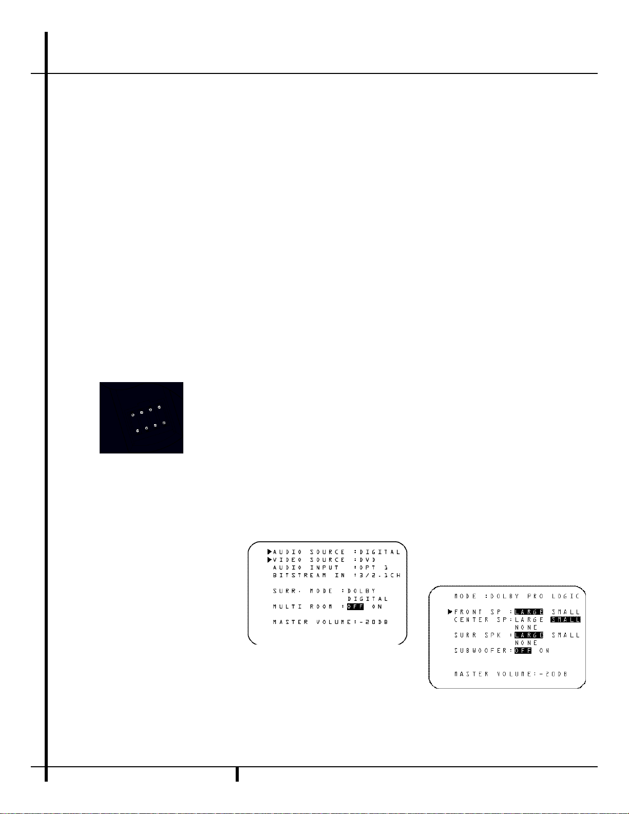
To view the Full-OSD screens,press the OSD
button q three times.The first press will bring
up the Semi-OSD mode and the second press
will turn the OSD system off;the third press will
call up the Full-OSD display (Figure 1).
When either OSD mode has been selected, a
message will appear at the bottom of the
screen any time the mode or source is changed.
First,the new mode or source will show,and if
the source is changed there will also be a confirmation of the mode in use.
Note that the full-screen displays will time-out
after 20 seconds. H o w e v e r, the on-screen display
used with the channel output level adjustments
will remain on the screen as long as the settings
are being changed.This display must be manually turned off by pressing the OSD button q.
Figure 1
When making most setup adjustments, the full
on-screen readout may be displayed at any
time by pressing the O S D button q o n c e.
The displays will remain on the screen as long
as adjustments are being made,or for twenty
seconds after the last button is pressed to
change a setting.
Speaker Configuration
The first few adjustments tell the AVR 300
which type of speakers are in use.This is
important as it adjusts the settings that determine which speakers receive low-frequency
(bass) information. For each of these settings
use the L A R G E setting if the speakers for a
particular position are traditional full-ra n g e
l o u d s p e a kers that are capable of reproducing
sounds below 100Hz. Use the S M A L L s e tting for smaller, frequency-limited satellite
s p e a kers that do not reproduce sounds below
1 0 0 H z . Note that when “ s m a l l ”s p e a kers are
u s e d , a subwoofer is required to reproduce
low-frequency sounds.Remember that the
“ l a r g e ” and “ s m a l l ” descriptions do not refer
to the actual physical size of the speake r s,b u t
their ability to reproduce low-frequency
s o u n d s.If you are in doubt as to which category describes your speake r s,consult the
specifications in the speakers’ owner’s manual,
or ask your dealer.
With the AVR 300 turned on, follow these steps
to configure the speakers:
1.Put the AVR 300 in the Dolby Pro Logic
mode by pressing the Dolby Pro Logic
Selector Ó on the front panel or by
pressing the Surround Mode Selector
f on the remote, followed by the
⁄/¤
buttons h until P R O L O G I C a p p e a r s
in the Main Information Display U a n d
the PRO LOGICindicator G l i g h t s.
2.Press the Speaker button
k
33
on the
remote or front panel. The words F R N T
S P E A K E R will appear in the Main
Information Display U.
If you are using the on-screen display system,a display will appear indicating the
status of each speaker (Figure 2).
Figure 2
3.Press the Set button i
31
and note
that the ›pointer will stop flashing.
16 SYSTEM CONFIGURATION
System Configuration
Page 18

17 SYSTEM CONFIGURATION
System Configuration
4. Press the
⁄/¤
buttons h on the
remote or the Selector buttons
3 4
on
the front panel until either L A R G E or
S M A L L appears,matching the type of
speakers you have at the left-front and
right-front positions,as described by the
definitions shown on preceding page.
When S M A L L is selected,l o w - f r e q u e n c y
sounds will be sent to the subwoofer output
o n l y.Note that if you choose this option,
and there is no subwoofer connected,y o u
will not hear any low-frequency sounds from
the front channels.
When L A R G E is selected,a full-range output will be sent to the front-left and frontright outputs,and NO low-frequency signals
will be sent to the subwoofer output.
N OT E : To use the On-Screen Display syst e m , press the O S D button q o n c e.Th e
selected speaker option will appear in
highlighted video.The selection will
change in response to the steps outlined
on these pages.
5 .When you have completed your selection for
the front channel,press the S e t button i
31
,and then press the
⁄/¤
buttons h
on the remote or the S e l e c t o r buttons
3 4
on the front panel to change the display to
C E N S P E A K E R .
6. Press the Set button i
31
again,and
use the
⁄/¤
buttons h on the remote,
or the Selector buttons
3 4
on the front
panel,to select the option that best
describes your system based on the speake r
definitions shown on preceding page.
When CEN SP S M A L L is selected,
low-frequency center-channel sounds will be
sent to the subwoofer output only. N o t e
that if you choose this option and there is
no subwoofer connected,you will not hear
any low-frequency sounds from the centerchannel speake r.
When C E N S P L A R G E is selected,a
f u l l - range output will be sent to the centers p e a ker output, and NO center channel signal will be sent to the subwoofer output.
When CEN SP N O N E is selected, no
signals will be sent to the center-channel
output.The receiver will operate in a
“phantom”center-channel mode and
center-channel information will be sent to
the left- and right-front channel outputs.
7.When you have completed your selection
for the center channel,press the Set but-
ton i
31
, and then press the
⁄/¤
buttons h on the remote or the
Selector buttons
3 4
on the front
panel to change the display to S U R
S P E A K E R.
8. Press the S e t button i
31
a g a i n ,a n d
then use the
⁄/¤
buttons h on the
remote or the S e l e c t o r buttons
34
on the
front panel to select the option that best
describes your system based on the speake r
definitions shown on preceding page.
When S U R S P S M A L L is selected,
low-frequency surround-channel sounds
will be sent to the subwoofer output only.
Note that if you choose this option and
there is no subwoofer connected,you will
not hear any low-frequency sounds from
the surround speaker.
When S U R S P L A R G E is selected,
a full-range output will be sent to the
surround-channel outputs, and NO sur-
round channel signals will be sent to the
subwoofer output.
When S U R S P N O N E is selected,
surround-sound information will be split
between the front-left and front-right outputs.Note that for optimal performance
when no surround speakers are in use, the
Dolby 3 Stereo mode should be used
instead of Dolby ProLogic.
9 .When you have completed your selection
for the surround channel,press the S e t
button i
31
,and then press the
⁄/¤
buttons h on the remote or the
S e l e c t o r buttons
3 4
on the front panel
to change the display to S - W SP E A K E R .
10.Press the Set button i
31
, and then
press the
⁄/¤
buttons h on the
remote or the Selector buttons
3 4
on
the front panel to select the option that
best describes your system.
Select S - W SP ON if a subwoofer is
connected to your system.
Select S - W SPOFF if a subwoofer is
NOT connected to your system.Note that
when no subwoofer is selected,lowfrequency sounds below 100Hz will be
sent to the front-left and front-right speake r s,
provided that the selection in Step 4 has
been set to L A R G E.O t h e r w i s e,no lowfrequency sounds will be heard at all.Th i s
option is not available when the front,c e n t e r
or surround speakers are set to S M A L L.
11.When all speaker selections have been
made,press the Set button i
31
to
return to normal operation.
Output Level Adjustment
Output level adjustment is a key part of the
configuration process for any surround-sound
product.It is particularly important for a Dolby
Digital receiver such as the AVR 300,as correct
outputs will ensure that you hear sound tracks
in their proper place with the proper directionality and intensity.
I M P O RTANT NOT E : Listeners are often confused about the operation of the surround
c h a n n e l s.While some assume that sound
should always be coming from each speake r,
most of the time there will be little or no
sound in the surround channels.This is because
they are only used when a movie director or
sound mixer specifically places sound there to
create ambiance,a special effect or to continue
action from the front of the room to the rear.
When the output levels are properly set it is
normal for surround speakers to operate only
o c c a s i o n a l l y.Artificially increasing the volume
to the rear speakers may destroy the illusion
of an enveloping sound field that duplicates
the way you hear sound in a movie theater or
concert hall.
Before beginning the adjustment process make
certain that all speaker connections have been
properly made.The system volume should be
set to the level that you will use during a typical listening session. Finally, make certain that
the Balance Control 7 is set to the center
“12 o’clock”position.
To adjust and calibrate the output levels,follow
these steps. For accurate calibration,it is a
good idea to make these adjustments while
seated in your favorite listening position:
1. Put the AVR 300 in the Dolby Pro Logic
mode by pressing the Dolby Pro Logic
Selector Ó on the front panel or by
pressing the Surround Mode Selector
f on the remote, followed by the
⁄/¤
Page 19

18 SYSTEM CONFIGURATION
System Configuration
buttons h until PRO LOGIC appears in
the Main Information Display U and
the PRO LOGIC indicator G lights up.
2 .Press the Test To n e button on the
r e m o t e.The words T-T FL 0 d B w i l l
appear in the Main Information Display
U ,and the letters F L will flash once each
s e c o n d .
NOTE:To use the on-screen display while
making output level adjustments, press the
OSD button q. A map of the installed
speakers will appear on your video screen
(Figure 3), and the channel where the test
noise should be heard will be indicated by
the highlighted lettering.As adjustments
are made,the numbers under the channel
location will increase or decrease to show
the change from the reference level.
Figure 3
3.At this point, the test noise will begin to
circulate among all the speakers in a clockwise rotation.
NOTE:This is a good time to verify that
the speakers have been properly connected.
As the test noise circulates, listen to make
certain that the sound comes from the
speaker position shown in the Main
Information Display. If the sound from
a speaker location does NOT match the
position indicated in the display, turn the
AVR 300 off using the Main Power
Switch 1 and check the speaker wiring
to make certain that each speaker is con-
nected to the correct output terminal.
4.After checking for speaker placement,let
the test noise circulate again,and listen to
see which channels sound louder than the
others.Using the front left (F L in the
display) speaker as a reference, press the
⁄/¤
buttons h on the remote or the
Selector buttons
on each channel to begin to bring them to
the same level.Note that when one of the
3 4
on the front p a n e l
buttons is pushed,the test noise circulation
will pause on the channel being adjusted to
give you time to make the adjustment.
When you release the button,the circulation will resume after 20 seconds.
5.Continue to adjust the individual speakers
until they all have the same volume.Note
that adjustments should be made with the
⁄/¤
buttons h on the remote or the
Selector buttons
only,NOT the main volume controls.Then
press the Set button i
rize the change. If you are using a sound
pressure (SPL) meter for precise level
adjustment, set the volume so that the
meter reads 75dB, C-Weighting Slow.
NOTE:The subwoofer output level is not
adjustable using the test tone.To change the
subwoofer level, follow the steps for Output
Level Trim Adjustment on page 25.
6.When you have adjusted the outputs so
that all channels have the same level,press
the Test Tone button on the remote
to complete the adjustment.
Delay Settings
Due the different distances between the frontchannel speakers and the listening position
compared to the surround speakers and the listening position,the amount of time it takes for
sound to reach your ears from the front or surround speakers is different.You may compensate for this difference through the use of the
delay settings to adjust the timing to tailor the
specific speaker placement and acoustic conditions in your listening room or home theater.
The factory setting is appropriate for most
rooms,but some installations create an uncommon distance between the front and surround
speakers that may cause the arrival of frontchannel sounds to become disconnected from
surround-channel sounds.
To resynchronize the front and surround channels,follow these steps:
1.Measure the distance from the listening/
viewing position to the front speakers.
2.Measure the distance from the listening/
viewing position to the surround speakers.
3 .S u b t ract the distance to the surround speak-
ers from the distance to the front speake r s.
34
on the front panel
31
to memo-
a.When setting the delay time for the
Dolby Digital surround modes, the optimal delay time is the result of that subtraction. For example, if the front speakers are ten feet away and the surround
speakers are five feet away,the optimal
delay time is figured as 10–5=5.Thus,in
this example, the delay time for Dolby
Digital should be set at five milliseconds.
b.When setting the delay time for the Pro
Logic mode,take the result of the subtraction and add 15 to obtain the optimal delay time. For example,if the front
speakers are ten feet away and the surround speakers are five feet away, the
optimal delay time is figured as
10–5+15=20.Thus,in this example,the
Pro Logic delay should be set at twenty
milliseconds.
NOTE:The DTS,Theater, Hall 1 and Hall 2
modes use a fixed,nonadjustable delay time.
The Dolby Digital Mode also includes a separate setting for the center-channel delay mode,
since the discrete nature of these signals makes
the location of the center-channel speaker more
critical.To calculate the delay for the center
channel, measure the distance from the preferred listening position in the center of the
room to both the center-channel speaker and
either the left or right speaker.
If the distances are equal,no further adjustment
is required and the center delay should be set to
z e r o.If the distance to the front speakers is
greater than the distance to the center speake r,
you may wish to reposition the speakers by
moving the front-left and front-right speake r s
closer to the listening position or the center
s p e a ker further away from the listening position.
If repositioning of the speakers is not possible,
adjust the center delay time, adding one millisecond of center-channel delay for every foot
closer to the listening position the center
speaker is than the front speakers.For example,
if the front-left and front-right speakers are
each 10 feet from the listening position and the
center-channel speaker is 8 feet away,the delay
is figured as 10–8=2,suggesting an optimal
center delay of 2 milliseconds.
Page 20

19 SYSTEM CONFIGURATION
System Configuration
To set the delay times, follow these steps:
1. Put the AVR 300 in the Dolby Pro Logic
mode by pressing the Dolby Pro Logic
Selector Ó on the front panel or by
pressing the Surround Mode Selector
f on the remote, followed by the
⁄/¤
buttons h until P R O L O G I C a p p e a r s
in the Main Information Display U a n d
the PRO LOGIC indicator G lights up.
2. Press the Delay button i˜ on
the remote or front panel. The words
S DELAY TIME will appear in the
Main Information Display U and at the
bottom of a video screen when the SemiOSD display is in use.
To use the on-screen display system while
making delay adjustments, press the OSD
button q until the full-screen menu
shown in Figure 4 appears on the screen.
Figure 4
3. Press the Set button i
31
.
4.Adjust the delay time by pressing the
⁄/¤
buttons h on the remote or the
Selector buttons
3 4
on the front panel
until the delay time figure calculated using
the formula entered above appears in the
display.
5 . If only analog sources will be used,n o
adjustment is needed for the center- c h a n n e l
d e l a y.In that case,press the S e tb u t t o n
i
31
to enter the surround delay settings into the AV R ’s memory.H o w e v e r,i f
you will be using digital sources and the
calculations outlined above indicate that
the center-channel delay requires an adjustm e n t ,continue with the following steps.
6.Before setting the center-channel delay
time,make certain that a digital source has
been selected.If a digital source is playing,
COAX A or OPTICAL C will
appear in the Main Information Display
U, along with the DIGITAL indicator
F. If a digital source is already connected
and playing,press the Delay button ˜ i
so that the words C DELAY TIME
appear in the Main Information Display
3 5
and proceed to step #10. If a digital
source is not playing,follow steps 7
through 10.
7.Press the Set button i31.
8 . Select the Dolby Digital mode either by
pressing the front panel Dolby Digital
S e l e c t o r ( or by pressing the S u r ro u n d
Mode Selector f on the remote,a n d
then pressing the
⁄/¤
buttons h on the
remote until DOLBY D appears in the
Main Information Display U or in the
on-screen display.Ignore any “N O
D A T A”message that may appear.
9.Press the Delay button i˜ on the
remote or front panel. The words S
D E L A Y T I M E appear in the M a i n
Information Display U.
1 0 .Press the
⁄/¤
buttons h on the remote
o n c e, so that C DELAY TIME
appears in the Main Information Display
U or in the on-screen display.
11.Press the Set button i
31
.
12.Press the
⁄/¤
buttons h on the
remote until the desired delay time for
the center channel appears in the display.
13.Press the Set button i
31
to enter
the setting into the AVR 300’s memory.
You have now completed the setup,adjustment
and calibration of the AVR 300.You are now
ready to enjoy the finest in music and home
theater listening.
Page 21
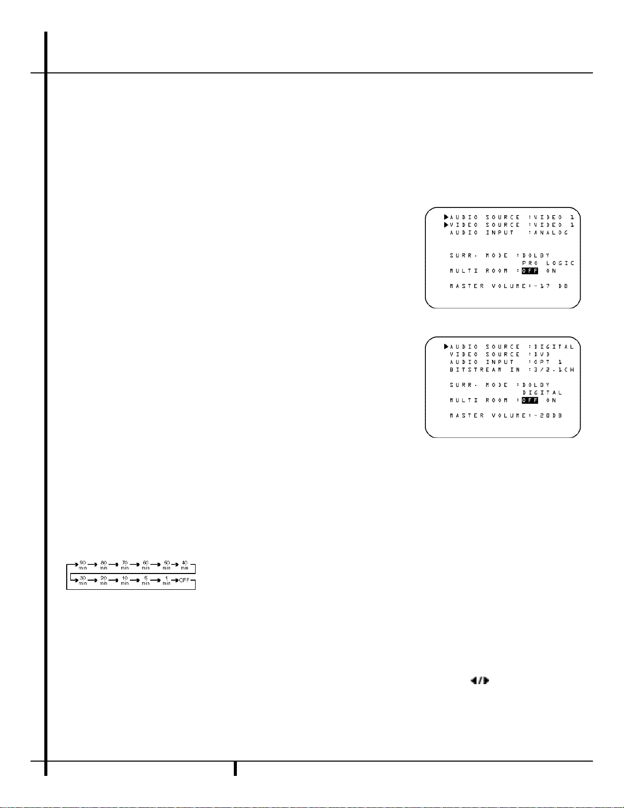
20 OPERATION
Operation
Basic Operation
Once you have completed the setup and configu ration of the AVR 300,it is simple to opera t e
and enjoy.The following instructions should be
followed for you to maximize your enjoyment of
your new receiver:
• When using the AVR 300 for the first time,y o u
must press the Main PowerS w i t c h1on the
front panel to turn the unit on.This places the
unit in a Standby mode,as indicated by the
amber color of the Power Indicator3.O n c e
the unit is in Standby, you may begin a listening
session by pressing the System Power Contro l
2
on the front panel or the AVR S e l e c t o r b
or C D / DV D Input Selectors c. Note that
the Power Indicator3will turn green.Th i s
will turn the unit on and return it to the input
source that was last used.The unit may also be
turned on from Standby by pressing any of the
Source Selector buttons on the remote l
m y or front panel
9 ) ! @ # $
.
To turn the unit off at the end of a listening
session,simply press the System Power
Control 2 on the front panel or the PowerOff Button d on the remote. Power to any
equipment plugged into the rear panel
Switched AC Outlet fl will be shut off and
the Power Indicator 3 will turn amber.
When the remote is used to turn the unit “ o f f”
it is actually placing the system in a Standby
m o d e,as indicated by the amber color of the
Power Indicator3.
• To program the AVR 300 for automatic turn-
o f f,press the S l e e p B u t t o n eon the remote.
Each press of the button will increase the time
before shut down in the following sequence:
The sleep time will be displayed in the
Information Display and it will count down until
the time has elapsed.
When the programmed time has elapsed,the
unit will automatically turn off. Note that the
front-panel display will dim to one-half brightness when the Sleep function is programmed.
To cancel the Sleep function, press and hold the
S l e e p B u t t o n e until the information
display returns to normal brightness and the
Sleep indicator numbers disappear.
When you will be away from home for an
extended period of time it is always a good
idea to completely turn the unit off using the
front panel Main Power Switch1.
NOTE:All preset memories are lost if the unit is
left turned off with the Main Power Switch
1
for more than two weeks.
Using the On-Screen Display
The AVR 300 is equipped with a powerful onscreen display system that makes it easy to view
the current status of the unit or to have messages appear to confirm any functional change,
such as a volume increase, input source select i o n ,or surround-mode selection.Two modes of
on-screen display are ava i l a b l e,a “ S e m i - O S D ”
mode that only displays a message when some
aspect of the operation is changed,and a “ F u l l O S D ” mode that displays a complete status
report on the unit’s current condition.
Semi-OSD
In the Semi-OSD mode,a one-line message will
appear at the bottom of the screen when
changes are made to the unit’s operational stat u s.To activate the Semi-OSD mode,press the
O S D button q o n c e.A confirmation message
(Figure 5) will appear briefly at the bottom of
your video display to remind you that this feature
is turned on.The message will time-out and
disappear after a few seconds.
When Semi-OSD mode is in use,single-line
messsages will appear at the bottom of the
screen to confirm changes to the volume,
source,surround mode or tuner frequency.
These messages,which will also be superimposed on any video program that is playing,
will disappear after a few seconds.
To turn off the Semi-OSD mode after it has been
a c t i va t e d , simply press the O S D button q
o n c e.When the OSD OFF m e s s a g e
a p p e a r s,the on-screen displays are deactiva t e d .
Full-OSD
An alternative display option is to have a fullscreen report of the AVR 300’s status appear.
To activate the Full-OSD,press the OSD button
q three times in quick succession. The first
press will turn the Semi-OSD on,the second
will turn the Semi-OSD off, and the third will
bring a full-status report to the screen.NOTE:
Full-OSD displays will always appear against a
blue background.Even if video is playing,they
will not be superimposed over the signal.To
view OSD items and video at the same time you
must use the Semi-OSD mode.
The status report will vary depending on the type
of audio input in use.For an analog source,t h e
first line in the display will show which audio
input is active (Figure 5).When a digital audio
source is in use, the display will indicate which
coaxial or optical input is active (Figure 6).
Figure 5
Figure 6
A c t i vating the Full-OSD will also simplify adjust-
ments to any system para m e t e r,as a full list of
choices will be shown.The selected option will
appear in reversed,highlighted video,while other
choices will appear in normal white on blue video.
The Full-OSD system may be turned off by
pressing the OSD button q once.
Display Brightness
In the normal,factory default setting ,the front
panel Information Display
3 5
will alwa y s
illuminate at full brightness.H o w e v e r, in some
installations you may prefer to have the display
appear at half brightness or not illuminate at all.
To adjust the setting so that the display lights at
other than full brightness,follow these steps:
• Press both Selector Buttons
3 4
a t
the same time.Note that V F D D I M M E R
will appear in the Main Information
D i s p l a y U.
Page 22

21 OPERATION
Operation
• Quickly release both buttons, and then
press and release the Set Button ˘. Th e
Main Information Display U will now
read VFD FULL.
• Within five seconds,press either of the
Selector Buttons
3 4
to choose either half
b r i g h t n e s s,as indicated by the display VFD
HALF,or completely off with the display
b l a n k .You may cycle through all of the options
by continually pressing the Selector
Buttons
3 4
. .
• When the desired brightness setting is reached,
Press Set Button
3 1
twice to return to normal.
Source Selection
• To select a source at any time,press any of
the Source Selector buttons on the remote
l m y or front panel
9 ) ! @ #
$
.
• The front-panel Video 3 Inputs8may be
used to connect a device such as a video game
or camcorder to your home entertainment
system on a temporary basis.
• When an audio source is selected the last
video input used remains routed to the Video
Outputs 1 ™ and TV Monitor Video
Output b.This permits simultaneously
viewing and listening to different sources.
• When a Video Input source is selected,t h e
video signal for that input will be routed to the
TV Monitor Video Outputjack b and will
be viewable on a TV monitor connected to the
AVR 300.M a ke certain that your TV is set to the
proper input to view the signal.
Volume Control
• Adjust the volume to a comfortable level
using the front-panel Volume Control ˆ or
remote Volume Up/Down buttons.
• When listening in the Stereo mode,with the
surround circuits off, the B a l a n c e Control 7
may be used to adjust the relative sound output
between the left-front and right-front speake r s.
• To temporarily silence all speaker outputs
press the Mute button ı. This will
interrupt the output to all speakers and the
headphone jack, but it will not affect any
recording or dubbing that may be in progress.
When the system is muted the MUTE indicator
W will light in the Information Display 35.
Press the Mute button
ı
again to
return to normal operation.
• During a listening session you may wish to
adjust the Bass Control 5and Treble
Control 6to suit your listening tastes or
room acoustics.
• For private listening,plug the 1/4" stereo
phone plug from a pair of stereo headphones
into the front-panel Headphone Jack4.
• In normal operation,when the AVR 300 is
turned on,it will always return to the volume
setting in effect when the unit was turned off.
However,for some installations you may prefer
to always have the AVR turn on at a specific
setting,regardless of the level when the unit
was turned off.To enter that mode and setting,
folow these steps:
1.Press both of the Selector
Buttons
3 4
. at the same time. Note that
VFD DIMMER will appear in the
Main Information Display U.
2.Quickly release both buttons,and then
press either one of the Selector
Buttons
3 4
. again and note that VOL
DEFAULT will appear in the Main
Information Display U.
3.To have the volume control always turn on
at the same level,press the Set Button
i and then release it. The Main
Information Display will now read Vol
Set Ð xxDB, with the actual
number being the current volume level.
4.Within five seconds,use the Volume
Control ˆ to set the desired volume level
for turn on.
5 .When the volume level is set, press the
S e t Button i
31
twice to return to
normal opera t i o n .
• To return the Volume Control setting at
turn on to the last volume level in use, f o l l o w
these steps:
1.Press both of the Selector Buttons
3 4
. at the same time. Note that VFD
DIMMER will appear in the Main
Information Display U.
2.Quickly release both buttons,and then
press either one of the Selector
Buttons
3 4
. again and note that VOL
DEFAULT will appear in the Main
Information Display U.
3.Press the Set Button i
31 .
.
4.Press the Selector Buttons
3 4
. until
DEFAULT OFF appears in the Main
Information Display U.
5.Press the Set Button i
31 .
twice to
return to normal operation.
Surround-Mode Selection
One of the most important features of the
AVR 300 is its ability to reproduce a full multichannel surround-sound field from digital
sources,analog matrix surround-encoded programs and standard stereo programs. In all, a
total of eight listening modes are available on
the AVR 300.
Selection of a surround mode is based on
personal taste, as well as the type of progra m
source material being used.For example,m o t i o n
pictures or TV programs bearing the logo of one
of the major surround-encoding processes,s u c h
as Dolby Surround,D T S Stereo or Ultra S t e r e o
may be played in either the Dolby Digital or
Dolby Pro Logic modes depending on the source
m a t e r i a l .
N OT E : Once a program has been encoded with
surround information, it retains the surround
matrix as long as the program is broadcast in
s t e r e o.Th u s,movies with surround sound will
carry surround information when they are broadcast via conventional TV stations,c a b l e,pay T V
and satellite tra n s m i s s i o n .In addition,a growing
number of made-for-television progra m s,s p o r t s
b r o a d c a s t s,radio dramas and music CDs are also
recorded in surround sound.You may view a list
of these programs at the Dolby Laboratories We b
site at www. d o l b y. c o m .
When a program is not listed as carrying intentional surround information,you may find that
the Pro Logic or Dolby 3 Stereo modes often
deliver enveloping surround presentations
through the use of the natural information present in all stereo recordings.H o w e v e r,for stereo,
but non-surround progra m s,we suggest that you
try the Hall 1, Hall 2 or Theater modes.
Surround modes are selected using either the
front-panel controls or the remote. To select a
surround mode from the front panel,simply
press the button that corresponds to the
(continued on page 23)
Page 23

22 OPERATION
Operation
MODE
DOLBY DIGITAL
DTS
DOLBY PRO LOGIC
DOLBY 3 STEREO
HALL 1 AND HALL 2
THEATER
STEREO
FEATURES
Available only with digital input sources encoded with Dolby Digital data. It provides
up to five separate main audio channels and a special dedicated Low-Frequency Effects
channel.
Available only with digital input sources encoded with DTS data.Available on special
DVD,LD and audio-only discs,DTS provides up to five separate main audio channels and
a special dedicated low-frequency channel.
The standard mode for analog surround sound decoding.It uses information encoded
in a two-channel stereo recording to produce four distinct outputs:Left,Center, Right and
a Mono Surround channel. Use this mode for accurate reproduction of programs bearing
the Dolby Surround,DTS Stereo,UltraStereo or other “Surround”logos.Surround-encoded
programs include videocassette,DVD and LD movies,TV and cable programs, radio
programs and audio CDs.Dolby Pro Logic processing may also be used to provide a
pleasing surround effect with some stereophonic source material that does not carry
surround encoding.
Uses the information contained in a surround-encoded or two-channel stereo program to
create center-channel information. In addition,the information that is normally sent to the
rear-channel surround speakers is carefully mixed in with the front-left and front-right
channels for increased realism. Use this mode when you have a center-channel speaker
but no surround speakers.
These modes are designed for use with stereo recordings.They provide a sound-field
effect that simulates the complex combination of direct and reflected sounds that
create the rich reverberant atmosphere of a medium-sized concert hall (Hall 1) or a
large concert hall (Hall 2).
Surround processing uses matrix surround decoding to simulate a standard movie or
stage theater.
This mode turns off all surround processing and presents the pure left and right
channel presentation of two-channel stereo programs.
DELAY TIME RANGE
Center:0 ms –5 ms
Surround: 0 ms –15 ms
Delay not adjustable
15 ms – 30 ms
Initial Setting = 20 ms
No surround channels
Hall 1 – Fixed at 41 ms
Hall 2 – Fixed at 67 ms
(not adjustable)
27.3 ms (not adjustable)
No surround channels
Surround-Mode Chart
Page 24

23 OPERATION
Operation
(continued from page 21)
desired mode ( Ó Ô Ò Ú .To
select a surround mode using the remote, p r e s s
the Surround Mode Selectorf, and then
press the
⁄/¤
buttons h to change the
mode.As you press the buttons,the Surround
mode name will appear in the Main
Information Display U,and an individual
mode indicator will also light up F G H I
J K.
Note that the Dolby Digital or DTS modes may
only be selected when a digital input is in use.
For more information on selecting digital sources,
see the following section of this manual.
To listen to a program in traditional two-channel
s t e r e o,using the front-left and front-right speakers only (plus the subwoofer if installed and
c o n f i g u r e d ) , press the S u r round Off b u t t o nÙ
on the front panel,or follow the instructions
shown above for using the remote until S U R R
O F F appears in the Main Information
Display U.When the AVR 300’s surround cir-
cuits are turned off,and it is in the Stereo mode,
the SURR OFF indicator K will illuminate
in the Information Display 35.
Digital Audio Playback
Digital audio such as Dolby Digital and DTS are a
major advancement over past systems.It delivers
five discrete channels:left front,c e n t e r,r i g h t
f r o n t ,left surround and right surround.E a c h
channel is full range and offers dra m a t i c a l l y
improved dynamic range and significant improvements to signal-to-noise ra t i o s.In addition,b o t h
of the digital systems have the capability to
deliver an additional channel that is specifically
devoted to low-frequency information.This is the
“ . 1 ”channel referred to when you see these
systems descibed as “ 5 . 1 ” .The bass channel is
totally separate but since it is intentionally bandwidth limited,sound designers have given it that
unique designation.
Dolby Digital
Dolby Digital (originally known as AC - 3®) is ava i lable on DVD and LD discs and is a part of the
new high-definition television (HDTV) system.
Note that an optional,external RF demodulator
is required to use the AVR 300 to listen to the
Dolby Digital sound tracks available on laser
discs.Connect the RF output of the LD player to
the demodulator and then connect the digital
output of the demodulator to the the Optical
or Coaxial inputs d e of the AVR 300.No
demodulator is required for use with DTSencoded laser discs.
DTS
DTS is another digital audio system that is
capable of delivering 5.1 audio. Although both
DTS and Dolby Digital are digital, they use different methods of encoding the signals,and
thus they require different decoding circuits to
convert the digital signals back to analog.
DTS-encoded sound tracks are available on
select DVD and LD discs, as well as on special
audio-only DTS discs.You may use any LD or
CD player equipped with a digital output to
play DTS-encoded discs with the AVR 300.All
that is required is to connect the player’s output
to either the Optical or Coaxial input on the
rear panel d e.
In order to listen to DVDs encoded with DTS
sound tracks, the DVD player must be compatible with the DTS signal as indicated by a DTS
logo on the player’s front panel.Note that early
DVD players may not be able to play DTSencoded DVDs.This does not indicate a problem with the AVR 300,as some players cannot
pass the DTS signal through to the digital outputs. If you are in doubt as to the capability of
your DVD player to handle DTS discs,consult
the player’s owner’s manual.
Selecting a Digital Source
To utilize either digital mode you must have
a digital source properly connected to the
AVR 300.Connect the digital outputs from DVD
players,HDTV receivers and CD players to the
Optical or Coaxial inputs on the rear panel
d e. In order to provide a backup signal and
a source for analog stereo recording,the analog outputs provided on digital source equipment should also be connected to their appropriate inputs on the AVR 300 rear panel (e.g.,
connect the analog stereo audio output from a
DVD to the DVD inputs ∞ on the rear panel
when you connect the source’s digital outputs).
When playing a digital source such as DVD,first
select the input using the remote or front-panel
controls as outlined in this manual.Next, select
the digital source by pressing the appropriate
Digital Input Selector button ¯ and then
using the
⁄/¤
buttons h on the remote or
the Selector buttons
3 4
on the front panel to
choose either of the two OPTICAL or
COAXIAL inputs, as they appear in the
Main Information Display U or on-screen
display.Press the Set button i ˘ to enter
the desired choice.When the digital source is
playing,the AVR 300 will automatically detect
whether it is a multichannel Dolby Digital or
DTS source, or a conventional PCM signal,
which is the standard output from CD players.
An indicator will light in the Information
Display to confirm the digital signal is Dolby
Digital F or PCM E and if the source is
COAX
A or
OPTICAL
C.
Digital Status
When a digital source is playing, the AVR 300
will automatically switch to the proper surround
mode.It is important to note, however, that not
all Dolby Digital or DTS sources are encoded
with the full complement of five channels plus
LFE.When a digital source is playing,the Main
Information Display U or on-screen display
will change to show the input source and
digital type (OPTICAL or COAX).When a
source with digital encoding is playing,the
input source name will appear in the
Information Display or on-screen display, followed by a numeric key indicating the type and
number of channels being decoded as follows:
3 / 2 . 1 : This message appears when a
full complement of Dolby Digital signals is
p r e s e n t : 3 front channels (left, center and
r i g h t ) , 2 surround channels (surround left
and surround right) and “ 1 ” c h a n n e l ,
which is the dedicated Low Fr e q u e n c y
Effects (LFE) channel.
3 / 1 : This message indicates the system
is decoding a standard Dolby Pro Logic signal with left-front, center and right-front
channels and a single mono surround
channel.
2 / 0 : This message indicates that the system is decoding a traditional two-channel
stereo signal and that no center, surround
or LFE signals are present.
1 / 0 : This is a monaural signal that plays
through the center-channel speaker only.
There is no sound at the front-left,f r o n t - r i g h t
or surround speake r s.
The current status of the AVR may also be
obtained by pressing the OSD Button q
until the Full-OSD appears on your video
d i s p l a y ’s screen.
Night Mode
A special feature of Dolby Digital is the Night
mode,which enables specially encoded input
Page 25

24 OPERATION
Operation
sources to be played back with full digital intelligibilty while reducing the minimum peak level
by 1/4 to 1/3.This prevents abruptly loud transitions from disturbing others without reducing
the impact of the digital source.The Night
mode is available only when Dolby Digital
signals with special data are being played.
To engage the Night mode, press the Night
buttonz on the remote and note that the
NIGHT mode indicator M will illuminate in
the Information Display and a message will
appear on the OSD.
IMPORTANT NOTES ON
DIGITAL PLAYBACK:
1.When the digital playback source is stopped,
or in a pause, fast forward or chapter search
mode,the digital audio data will momentarily
stop, causing a N O D A T A message to be displayed in the Main Information Display U
or on-screen display.This is normal and does
not indicate a problem with either the AVR 300
or the source machine.The AVR 300 will return
to digital playback as soon as the data is avail-
able and when the machine is in a standard
play mode.
2 .Although the AVR 300 will decode virtually all
DVD movies,CDs and HDTV sources,it is possible
that some future digital sources may not be com-
patible with the AVR 300.
3. Note that not all digitally encoded programs
contain full 5.1 channel audio. Consult the pro-
gram guide that accompanies the DVD or laser
disc to determine which type of audio has been
recorded on the disc. The AVR 300 will auto-
matically sense the type of digital surround
encoding used and adjust to accommodate it.
4.When a digital source is playing, you may not
select any of the analog surround modes such
as Dolby Pro Logic, Dolby 3 Stereo,Hall 1/2 or
Theater.
5.When a Dolby Digital or DTS source is play-
ing,it is not possible to make an analog record-
ing using the Tape g and VCR 1 ™ record
outputs.However, the digital signals will be
passed through to the digital audio outputs ª.
PCM Audio Playback
PCM (Pulse Code Modulation) is the non-
compressed digital audio system used for
compact discs and Dolby Digital or DTS laser
d i s c s.The digital circuits in the AVR 300 are
capable of high-quality digital-to-analog decodi n g ,and they may be connected directly to the
digital audio output of your CD or LD player.
Connections may be made to either the O p t i c a l
or C o a x i a l inputs d e on the rear panel.
To listen to a PCM digital source,first select the
input for the desired source (e. g . ,C D ) .Next press
the D i g i t a lSelect button ¯ k and then
use the
⁄/¤
buttons h on the remote or the
S e l e c t o r b u t t o n s
3 4
on the front panel until
the desired choice of either O P T I C A L o r
C O A X appears in the Main Information
Display U. Press the S e t button i
31
t o
enter the desired choice.
When a PCM source is playing,the P C M indi-
cator E will light,and the Main Information
Display will show the input source and the digital type.During PCM playback you may select
any surround mode except Dolby Digital.When
an audio-only DTS disc is played,the AVR will
automatically select the DTS mode, and no
other mode may be selected.
Tuner Operation
The AVR 300’s tuner is capable of tuning A M ,
FM and FM Stereo broadcast stations. S t a t i o n s
may be tuned manually, or they may be stored
as favorite station presets and recalled from a
30-position memory.
Station Selection
1.Press the AM/FM button $y to select
the tuner as an input.
2.Press the AM/FM button $y again to
switch between AM and FM so that the desired
frequency band is selected.
3.Press the Tuner Mode button
*
n
to select manual or automatic tuning.
When the AU TOindicator Q is illuminated in
the Main Information Display the tuner will only
stop at those stations that have a strong enough
signal to be received with acceptable quality.
When the MONO indicator R is illuminated,
the tuner is in a manual mode and will stop at
each frequency increment in the selected band.
4.To select stations press the Tuning button
%
w.When the AUTO indicator Q is
illuminated,press the buttons for two seconds
and then release to cause the tuner to search
for the next highest or lowest frequency station
that has an acceptable signal.When tuning FM
stations in the Auto mode,the tuner will only
select Stereo stations.To tune to the next station,press the button again.If the MONO indi-
cator R is illuminated, tap the Tuning button
%
w to advance one frequency increment at
a time,or press and hold it to locate a specific
station.When the TUNED indicator T illumi-
nates,the station is properly tuned and should
be heard with clarity.
5.Stations may also be tuned directly by pressing the Direct button s on the remote, and
then pressing the Numeric Keys p that correspond to the station’s frequency.The desired
station will automatically be tuned.
NOTE:When the FM reception of a station is
weak,audio quality will be increased by
switching to Mono mode by pressing the
Tuner Mode button *n until the
S T E R E O indicator S goes out.
Preset Tuning
Up to 30 stations may be stored in the
AVR 300’s memory for easy recall using the
front-panel controls or the remote.
To enter a station to the memory, first tune the
station using the steps outlined above;then:
1.Press the Memory button o on the
remote.Note that MEMORY indicator P will
illuminate and flash in the Information Display.
2.Within five seconds,press the Numeric
Keys p corresponding to the location where
you wish to store this station’s frequency.
3.Repeat the process after tuning any
additional stations to be preset.
Recalling Preset Stations
• To manually select a station previously
entered in the preset memory, press the
Numeric Keys p that correspond to the
desired station’s memory location.
• To manually tune through the list of stored
preset stations one by one, press the Preset
buttons & v on the front panel or remote.
• To automatically scan through the stations
entered in the preset memory,press the
P reset Scan button ^on the front panel.
Page 26

25 OPERATION
Operation
The tuner will run through the list of preset
s t a t i o n s,stopping for five seconds at each one.
Press the button again to stop the scan at your
desired station.
• To view a list of the stations entered in the
preset memory,press the OSD button q t o
bring up the Full-OSD screen while the tuner is
in use and then press the Memory b u t t o n
o.The video display screen will show the
first 16 stations that have been preset, a s
shown in Figure 7.
Figure 7
The word NONE simply indicates that no sta-
tion information has been entered and that the
memory slot is ava i l a b l e.To view the remaining
s t a t i o n s,press the Numeric Keys p for a
preset number not on the list, and the display
will change.
Tape Recording
In normal operation, the audio or video source
selected for listening through the AVR 300 is
sent to the record outputs. This means that any
program you are watching or listening to may
be recorded simply by placing machines connected to the outputs for Tape Out g or
Video 1 ™ in the record mode.
When a digital audio recorder is connected to
the digital outputs ª,you are able to record
the digital signal to a CD-R,MiniDisc or other
digital recording system.
NOTES:
• The digital outputs are active only when a
digital signal is present,and they do not
convert an analog input to a digital signal,
or change the format of the digital signal.
In additonal,the digital recorder must be
compatible with the output signal. For
example,the PCM digital input from a CD
player may be recorded on a CD-R or
MiniDisc,but Dolby Digital or DTS signals
may not.
• Please make certain that you are aware of
any copyright restrictions on any material you
copy.Unauthorized duplication of copyrighted
materials is prohibited by Federal law.
Output-Level Trim Adjustment
Normal output-level adjustment for the
AVR 300 is established using the Test Tone, as
outlined on page 18. In some cases, however,it
may be desirable to adjust the output levels
using program material such as a test disc,or a
selection you are familiar with.Additionally,the
output level for the subwoofer can only be
adjusted using this procedure.
To adjust the output levels using program
material, first set the reference volume for the
front-left and front-right channels using the
Volume Control ˆ . If you wish to vary
the difference between the left and right channels,use the Balance Control 7.
Once the reference level has been set, p r e s s
the Channel Select button gand note that
FRONT L LEV will appear in the M a i n
Information Display U. To change the
l e v e l , first press the S e t button i
31
, a n d
then use the S e l e c t o r buttons
3 4
or the
⁄/¤
buttons h to raise or lower the level.
D O N OT use the volume control, as this will
alter the reference setting.
Adjusting the output-level trim is easier when
the Full-OSD system is used.To do this, f i r s t
press the Channel Select Button g a n d
then press the OSD button so that the display
shows all available speaker positions as shown
in Figure 8. Note that there will be a flashing
pointer under the F L, or front-left position.
When the Set button i is pressed to start
a d j u s t m e n t s, the pointer will stop flashing.
During adjustments the numbers will increase
or decrease to indicate the change from the
reference-level setting.
Figure 8
Once the change has been made,press the Set
button i
3 1
and then press the Selector
buttons
3 4
or the
⁄/¤
buttons h to select
the next output channel location that you wish
to adjust. To adjust the subwoofer level,press
the Selector buttons
3 4
or the
⁄/¤
b u t t o n s
h until S-WOOFER LEV appears in the
Main Information Display U.
Press the S e t button i
3 1
when the name
of the desired channel appears in the Main
Information Display U, and follow the
instructions shown earlier to adjust the level.
Repeat the procedure as needed until all channels requiring adjustment have been set.When
all adjustments have been made and no further
adjustments are made for twenty seconds, the
AVR 300 will return to normal operation.
NOTE:The output levels may be separa t e l y
trimmed for each digital and analog surround
m o d e.If you wish to have different trim levels for
a specific mode,select that mode using the front
panel buttons
( Ó Ô Ò
Ú or
f on the remote control and follow the instruc-
tions in the steps shown above.
6-Channel Direct Input
The AVR 300 is equipped for future expansion
through the use of optional, external adapters
for formats that the AVR 300 may not be capable of processing.When an adapter is connected
to the 6-Channel Direct Input §,you may
select it by pressing the 6-Ch Input Selector
l
#
.
Note that when the 6-Channel Direct Input is in
use, you may not select a surround mode,as
the external decoder determines processing. In
addition, there is no signal at the record outputs when the 6-Channel Direct Input is in use.
Memory Backup
This product is equipped with a memory backup
system that preserves tuner presets and system
configuration information if the unit is accidentally unplugged or subjected to a power outage.This memory will last for approximately
two weeks, after which time all information
must be reentered.
Page 27

26 MULTIROOM OPERATION
Multiroom Operation
The AVR 300 is fully equipped to operate
as the control center for a sophisticated multi-
room operation with optional remote external
InfraRed (IR) sensors, speakers and power
a m p l i f i e r s.Although some multiroom installations will require the services of a specially
trained installer, it is possible for the average
do-it-yourself hobbyist to install a simple
remote room system.
Installation
The key to remote room operation is to link the
remote room to the AVR 300’s location with
wire for an infrared receiver and speakers or an
amplifier. For complete installation instructions
for multiroom use, see page 14.
Multiroom Setup
Once the audio and IR link connections have
been made,the AVR 300 needs to be configured
for multiroom operation using the steps below.
When making these selections,you may use the
front-panel Information Display,or use the OnScreen Display System. Either the Semi-OSD system may be used,in which case the choices will
appear as a single-line display at the bottom of
the screen,or the full-screen display may be used.
When the Full-OSD display system is in use,t h e
complete list of choices will appear on the screen.
To activate the Semi-OSD,press the O S Db u t t o n
q o n c e.To activate the Full-OSD, press the
O S D button q three times.This will turn the
Semi-OSD on and then off.The Full-OSD will
appear after the third button press.
Once you have determined which,if any, O S D
system to use,setup and operation of the multi-
room system is simple.
1. Press the M u l t i button ` to initiate the
multiroom system.If the Semi-OSD system is
e n g a g e d , a message will appear at the bottom of the screen.If the Full-OSD system is
e n g a g e d , the complete multiroom menu
(Figure 9) will be shown on the video display.
Press the S e t button i within twenty
seconds to enter the multiroom menus.
Figure 9
2 .Press the ⁄or ¤buttons h to turn the
multiroom system on or off, as indicated by
the front-panel Information Display message,
the Semi-OSD message,or the change in the
highlighted video in the Full-OSD screen. P r e s s
the S e t button i to enter the settings.
3.Press the ¤Button h to move to the input
settings.Press the Set button i to change
the input source. Press the
⁄/¤
buttons
h to select the desired input. When the
input source you wish to send to the remote
room location appears on the front-panel
Information Display,in the lower screen SemiOSD message,or is highlighted in reverse
video in the Full-OSD listing,press the S e t
button i to enter the selection.
4.Press the
⁄/¤
buttons h to move to the
multilevel setting.Press the Set button i
if you wish to change the output level.
Within twenty seconds, press the ⁄or
¤
buttons h to change the output level for
the multiroom feed. The volume change will
appear as a number in dB increments below
the 0dB reference level in the front-panel
Information Display, as a lower third SemiOSD message,or as the last line in the
Full-OSD status display.
5.Press the Set button i to enter the set-
ting.If no further buttons are pressed within
five seconds, the unit will return to normal
operation.
Multiroom Operation
To activate the feed to the remote room,press
the Multi button ` on the remote. Next,
press the Set button i. Press the
⁄/¤
buttons h to turn the multiroom feed on or off.
When the multiroom system is on, the M U LT I
indicator L will light in the Information
Display35,and the Main Information
Display U or OSD will display MUL
ROOM ON. Press the Set button i to
enter the setting.
When the multiroom system is turned on,t h e
previously selected input will be fed to the M u l t i
O u t jacks • on the rear panel.The volume will
be as set in the previous selection,although it
may also be adjusted using an optional volume
control in the remote location or on the optional
audio power amplifier connected to the M u l t i
O u t jacks •.
If an optional IR sensor is located in the remote
room and connected to the AVR 300’s Multi IR
jack ¤,the multiroom system may be turned
on or controlled by simply pointing the AVR 300
r e m o t e,or an optional programmable remote
that includes codes for the AVR 300,at the IR
s e n s o r.Note that depending on the type of prog rammable remote used, the code for the AV R ’s
Multi button may not be contained in the
p r e p r o g rammed code libra r y,and must be
“ l e a r n e d ”into the remote,if possible.
To change the input source for the multiroom
feed once it has been turned on,follow the
instructions on this page.
Once the multiroom system is turned on, it will
remain on even if the AVR 500 is placed in the
Standby mode in the main room by pressing
the Power-Off Button d or the System
Power Control 2 on the front panel. To turn
off the multiroom sysytem,even when the AVR
is in Standby mode in the main listening room,
press the Multi button ` and then the Set
button i. Press the
⁄/¤
buttons h so
that the M U LT I indicator L in the Infor-
mation Display35goes out, and the Main
Information Display U or OSD will display
MUL ROOM OFF.Press the Set button
i to enter the setting and turn the unit off.
Even when the AVR is turned off in the main
room,the multiroom system may be turned on
at any time by pressing the Multi button `.
Page 28

27 PROGRAMMING THE REMOTE
Programming the Remote
The AVR 300 includes a powerful remote control that is preset to operate all AVR functions
and most Harman Kardon products. In addition,
the remote contains the codes for most popular
brands of audio and video equipment,including
CD,DVD and LD players; cassette decks;cable
boxes;VCRs; and satellite receivers.Once the
remote is programmed with the codes for the
equipment in your system,you may eliminate
most other remotes,replacing them with of a
single,universal remote control.
Programming the Remote
As shipped from the factory,the remote
is fully programmed for all AVR 300 functions,a s
well as those of most Harman Kardon CD change r s,CD and DVD players,and cassette decks.I n
a d d i t i o n ,by following one of the methods below,
you may program the remote to operate a wide
range of devices from other manufacturers.
Direct Code Entry
This method is the easiest way to program your
remote to work with different products.
1.Use the tables in the following pages to
determine the three-digit code or codes that
match both the product type (e.g.,VCR,TV),
and the specific brand name. If there is
more than one number for a brand,make
note of the different choices.
2.Turn on the product you wish to program
into the AVR 300 remote.
3.Press and hold both the Input or Video
Device Selector c for the type of
product to be entered (e.g.,VCR,TV) and
the Mute button at the same time.
Hold both buttons until the red light under
the Selector button stays lit.Note that the
next step must take place while the red
light is on,and it must begin within 20
seconds after the light illuminates.
4. Point the AVR 300’s remote towards the unit
to be progra m m e d , and enter the first threedigit code number using the N u m e r i c b u ttons p.If the unit being programmed turns
o f f,the correct code has been entered.P r e s s
the Input or Video Device Selectorc
a g a i n , and note that the red light will
flash twice before going dark to confirm
the entry.
5.If the product to be programmed does NOT
turn off,continue to enter the three-digit
code numbers until the equipment turns off.
At this point,the correct code has been
entered.Press the Input or Video Device
S e l e c t o r c again and note that the
red light will flash twice before going dark
to confirm the entry.
6.Try all of the functions on the remote to
make certain that the product operates
properly.Keep in mind that many manufacturers use a number of different combinations of codes, so it is a good idea to make
certain that not only does the Power control
work,but that the volume,channel and
transport controls work as they should.If
functions do not work properly, you may
need to use a different remote code.
7 . If a code cannot be entered to turn the
unit off, if the code for your product does
not appear in the tables in this manual, o r
if not all functions operate properly,t r y
p r o g ramming the remote with the A u t o
Search Method.
Auto Search Method
If the unit you wish to include in the AVR 300’s
remote is not listed in the code tables in this
manual or if the code does not seem to opera t e
p r o p e r l y,you may wish to program the correct
code using the Auto Search method that follows:
1.Turn on the product that you wish to
include in the AVR 300 remote.
2. Press the Input or Video Device Selector
c for the type of product to be
entered (e. g . ,V C R ,TV) and the M u t e b u t t o n
at the same time.Hold both buttons
until the red light under the button stays lit.
Note that the next step must take place
while the red light is on,and it must begin
within 20 seconds after the light illuminates.
3. Point the AVR 300 remote towards the
unit to be progra m m e d , and press and
hold the Channel Selector b u t t o nf.Th i s
will send out a series of codes from the
r e m o t e ’s built-in data base, with each flash
of the red light under the Input or Vi d e o
Device Selectorc indicating that a
code has been sent.When the device to be
p r o g rammed turns off,I M M E D I AT E L Y release
the Channel Selector b u t t o nf.
4.Press the Input or Video Device
Selector c again, and note that the
red light will flash twice before going dark
to confirm the entry.
5.Try all of the functions on the remote to
make certain that the product operates.
Keep in mind that many manufacturers use
a number of different combinations of
codes, and it is a good idea to make certain
that not only the Power control works,but
the volume, channel and transport controls,
as appropriate. If all functions do not work
properly, you may need to Auto-Search for a
different code,or enter a code via the Direct
Code Entry method.
Code Readout
When the code has been entered using the A u t o
Search method,it is always a good idea to find
out the exact code so that it may be easily reentered if necessary.You may also read the codes
to verify which device has been programmed to
a specific Control Selector button.
1 . Press and hold both the Input or Vi d e o
Device Selector c for the type of
product to be entered (e. g . ,V C R ,TV) and
the M u t e b u t t o n at the same time.
Hold both buttons until the red light under
the button stays lit. Note that the next
step must take place while the red light is
o n , and it must begin within 20 seconds
after the light illuminates.
2 .Press the Digital Select/Exitbutton k.
The red light under the Input or Vi d e o
Device Selector c will blink in a
sequence that corresponds to the three-digit
c o d e,with a one-second pause between each
d i g i t .Count the number of blinks between
each pause to determine the digit of the
c o d e. One blink is the number 1,two blinks is
the number 2,and so forth.Ten blinks are
used to indicate a “ 0 ” .
Example:One blink,followed by a one-second
pause,followed by six blinks,followed by a
one-second pause, followed by ten blinks indi-
cates that the code has been set to 160.
For future reference enter the Setup Codes for
the equipment in your system here:
CD______________ DVD ____________
C B L _ _ _ _ _ _ _ _ _ _ _ _ _ _SAT ______________
TV ______________VCR______________
Page 29

28 PROGRAMMING THE REMOTE
Programming the Remote
P ro g rammed Device Functions
Once the AVR 300’s remote has been pro-
g rammed for the codes of other devices, p r e s s
the appropriate Input or Video Device
S e l e c t o r c to change the remote from
control over the AVR 300 to the additional prod-
u c t .When you press any of these buttons,it will
briefly flash in red to indicate that you have
changed the device being controlled.
When operating a device other than the
AVR 300,the controls may not correspond
exactly to the function printed on the remote
or button.Some commands,such as the volume
c o n t r o l , are the same as they are with the
AVR 300.Other buttons will change their func-
tion so that they correspond to a secondary
label on the remote.For example,the Sleep
and Surround Mode selector buttons also function as the Channel Up and Channel Down
buttons when operating most TV sets,VCRs or
cable box e s.The Channel Up/Down indication is
printed directly on the remote.The same is true
for standard CD player,cassette deck,VCR and
DVD functions, which follow the standard function icons printed on top of the buttons.
For some products, however,the function of a
particular button does not follow the command
printed on the remote. In order to see which
function a button controls, consult the Function
List tables printed on page 30.To use those
tables, first check the type of device being con-
trolled (e.g.,TV,VCR).Next,look at the remote
control diagram pictured on page 29.Note that
each button has a number on it.
To find out what function a particular button
has for a specific device, find the button num-
ber on the Function List and then look in the
column for the device you are controlling. For
example,button number 8 is the Test Tone
button for the AVR 300, but it is the “Favorite”
button for many VCRs and Satellite receivers.
Button number 39 is the Preset Tune Down button for the AVR 300,the “Reverse Skip”button
for CD players and the “Page Down” button for
some cable boxes.
Note that the numbers used to describe the
button functions on page 30 for the purposes
of describing how a button operates are a different set of numbers than those used in the
rest of this manual to describe the button
functions for the AVR.
Notes on Using the AVR 300 Remote With
Other Devices.
• Manufacturers may use different code sets for
the same product category.For that reason,i t
is important that you check to see if the code
set you have entered operates as many controls as possible. If it appears that only a few
functions opera t e,check to see if another
code set will work with more buttons.
• When a button is pressed on the AVR 300
remote,the red light under the Input or
Video Device Selector c for the
product being operated should flash briefly.
If the Device Control Selector flashes for
some but not all buttons for a particular
product,it does NOT indicate a problem with
the remote, but rather that no function is
programmed for the button being pushed.
Macro Programming
Macros enable you to easily repeat frequently
used combinations of commands with the press
of a single button on the AV R ’s remote control.
Once progra m m e d ,a macro will send out
up to eight different remote codes in a predetermined sequential order enabling you to
automate the process of turning on your system,
changing devices,or other common tasks.Th e
AV R ’s remote can store up to five separa t e
macro command sequences,one that is associated with the Power Button d, and four more
that are accessed by pressing the Macro Buttons
r s t.
1.Press any of the Input or Video Device
S e l e c t o rs c and the Mute button
at the same time until the red light
under the Device Control Selector turns on.
2.Press the button on the remote that you
wish to use for this macro.This may be
either the Power button d or any of the
four Macro buttons r s t.However,
it is recommended that to avoid confusion,
the Power button only be used to enter
turn-on/turn-off sequences.When you press
the button the macro will be programmed
to,the light under Selector button c
will blink once.
3.Enter up to eight steps for the macro
sequence by pressing the Selector button
c for the device to be controlled
and then pressing the button for the actual
command step.Although the macro may
contain up to eight steps, each button press
counts as a step, including those used to
change devices.The red light under the
Selector button c will blink once
to confirm each button press as you enter
commands.
N OT E : While entering commands for Po w e r
On/Off of any device during a macro sequence,
press the M u t e button . D ON OT press the
actual Power button.
4 .When the eight steps have been entered,
press the Channel Up button f t o
store the commands. The red light under
the Input or Video Device Selectors
c will blink and then turn off.
Example:To program your TV, Cable Box
and the AVR 300 to turn on when the
Power button is pressed,first press and hold
down the AV R b and M u t e buttons
until the red light comes on under the AV R
b u t t o n .N e x t , press the M u t e button t o
enter the Power command for the AV R .P r e s s
the TV Device Control Selector to
select the TV mode,and then press the
M u t e button a g a i n ,to select TV Po w e r.
F i n a l l y,press the CBL Device Control
Selector followed by the M u t e b u t t o n
to select Cable Po w e r. Press the
Channel Up button f to enter the com-
m a n d s.
After following these steps, each time you
press the Power button d, the remote
will send the Power On/Off command.
To remove a macro program,follow steps 1,2
and 4 above, but ignore step three. For example,to erase the macro just entered,press the
Device Selector c and the Mute
button at the same time until the red light
under the Device Control Selector turns on.
Press the Power button d and then press
the Channel Up button f. The red light
under the Device Control Selector c
will blink twice to confirm the data entry and
then turn off.
Volume Punch-Through
The AVR 300’s remote may be programmed to
operate the Volume Control from either
the TV or the AVR in conjunction with any of
the eight devices controlled by the remote.For
example, since the AVR 300 will likely be used
as the sound system for TV viewing,you may
wish to have the AVR’s volume activated
although the remote is set to run the TV. Either
the AVR or TV volume control may be associated
with any of the remote’s devices.To program
Page 30

29 PROGRAMMING THE REMOTE
Programming the Remote
the remote for Volume Punch-Through,follow
these steps:
1. Press the Input o rVideo Device Selector
c for the unit you wish to have associated with the volume control and the M u t e
button at the same time until the red light
illuminates under the Device Selector.
2.Press the Volume Upbutton .
3.Press either the AV Rb or the TV Device
C o n t rol Selector , depending on which
s y s t e m ’s volume control you wish to have
attached for the punch-through mode.N o t e
that the red light under the Device Contro l
S e l e c t o r will blink twice and then go out
to confirm the data entry.
Example:To have the AVR’s volume control
activated even though the remote is set to
control the TV, first press the TV Device
C o n t rol Selector and the M u t e b u t t o n
at the same time.N e x t , press the
Volume Up button , followed by the
AVR Device
C o n t rol Selector b.
N OT E : Should you wish to return the remote to
the original configuration after entering a Vo l u m e
P u n c h - Th r o u g h , you will need to repeat the steps
shown above.H o w e v e r,press the s a m e D e v i c e
Control Selector in steps one and three.
Reassigning Device-Control
Selectors
Although any of the Input o rVideo Device
S e l e c t o rs c is normally assigned to the
category of product shown on the remote,it is
possible to reassign one of these buttons to operate a second device of another type.For example,
if you have two VCRs but no cable box receiver,
you may program the CBL button to opera t e
a second V C R .Before following the normal prog ramming steps for either Three-Digit entry or A u t o
Search code entry,you must first reassign the
button with the following steps:
1.Press the Input o r Video Device Selector
c you wish to reassign and the M u t e
button at the same time until the red
light illuminates under the Device Contro l
Selector .
2.Press the Input o rVideo Device Selector
c for the function you wish to
p r o g ram into the reassigned button.
3.Enter the three-digit code for the specific
model you wish the reassigned button to
operate.
4.Press the same Input o r Video Device
S e l e c t o rc pressed in Step 1 once
again to store the selection.
Example: To use the CBL button to operate a
second VCR,first press the CBL Device
C o n t rol Selector and the M u t e b u t t o n
at the same time until the red light glows
under the CBL button.Press the VCR button,
followed by the three-digit code for the specific
model you wish to control.F i n a l l y,press the
CBL button again.
Page 31

30 SETUP CODES
Function List
No. Button Name CD/CDR DVD Tape TV VCR CBL SAT
1 AVR Selector
2 TVSelector Power On
3 CD Selector Power On
4 DVD Selector Power On
5 CBL/SATSelector Power On Power On
6 VCRSelector Power On
7 Power Off Power Off Power Off Power On/Off Power On/Off Power On/Off Power On/Off
8 Test Input Select Fav Fav
9 TV/VCR
10 Surround Select CDR Select Skip Fwd Channel + Channel + Channel + Channel +
11 Sleep
CDP Select
12 Volume Up Input Level Up Volume Up Volume Up Volume Up Volume Up
13 Surround Select Skip Rev Channel – Channel – Channel – Channel –
14 Mute Mute Mute Mute
15 Volume Down Input Level Down Volume Down Volume Down Volume Down
16 Channel Title Guide Guide Guide Guide
17 Speaker Intro Scan Menu Menu Menu Menu Menu
18
⁄
Up Up Up Up Up
19
fi
Left Left Left Left Left
20 Set Enter Select Select Select Select
21
fl
Right Right Right Right Right
22 Digital Select/Exit Record Subtitle Exit Exit Exit Exit
23
¤
Down Down Down Down Down
24 Delay/Prev. Channel Open/Close Return Prev. Channel Prev.Channel Prev.Channel
25 Vid 1 Select Track Direct Sub W On/Off Music Alt
26 6 Ch Select
27 Night Pause Pause Rec./Pause Rec./Pause
28 Multi Room Stop Stop Stop Stop
29 Vid 2 Select Track Increment Open/Close
30 AM/FM
31 Transport Reverse Play Reverse
32 Transport forward Play Play Play forward Play
33 Vid 3 Select Disk Skip Disk Skip
34 Tuner Mode
35 Tuning Down
fifi
Rev Search Rev Search Rewind Rewind Say –
36 Tuning Up
flfl
Fwd Search Fwd Search Fast Forward Fast forward Day +
37 Tape Selector
38 Memory
39 Preset
‡fi
Rev Skip Rev Slow Page –
40 Preset
fl·
Fwd Skip Fwd Slow Page +
41 1 1 1 1 1 1 1
42 2 2 2 2 2 2 2
43 3 3 3 3 3 3 3
44 4 4 4 4 4 4 4
45 5 5 5 5 5 5 5
46 6 6 6 6 6 6 6
47 7 7 7 7 7 7 7
48 8 8 8 8 8 8 8
49 9 9 9 9 9 9 9
50 0 0 0 0 0 0 0
51 OSD/Info Program Info Info
52 Enter Enter Enter Enter
53 Macro 1 Time Audio
54 Macro 2 Repeat Angle PPV
55 Direct/Macro 3 Random Play Chapter
56 Clear/Macro 4 +10 Clear Bypass Next
Page 32

31 SETUP CODES
Setup Code Tables:TV
Manufacturer/Brand Setup Code Number
ADMIRAL 072 081 161
AKAI 001 167
AMPRO 073 167
ANAM 043 054 055 056 080 104 108 112 118 121
AOC 001 004 058 112
CANDLE 001 002 003 004
CAPEHART 058
CENTRONIC 043
CITIZEN 001 002 003 004 101 143
CLASSIC 043
CONCERTO 004
CONTEC 043 051
CRAIG 054
CROWN 143
CURTIS MATHES 001 004 101 143
DAEWOO 004 055 103 111 114 127 143
DAYTRON 004 143
DWIN 177
DYNATECH 062
ELECTROHOME 024 143
EMERSON 001 004 005 028 043 047 048 051 096 143 151 153 154 155
FISHER 007 057
FUNAI 028 043
FUTURETECH 043
GE 004 008 009 034 056 073 074 091 130 144 155 160 161
GOLDSTAR 004 106 110 112 113 119 127 143
HITACHI 004 007 010 011 012 023 075 143 158 163
INFINITY 164
INKEL 129
JBL 164
Page 33

32 SETUP CODES
Setup Code Tables:TV (continued)
Manufacturer/Brand Setup Code Number
JC PENNEY 004 008 024 030 065 101 143 160
JENSEN 013
JVC 034 038 070 083
KENWOOD 001 070
KLOSS 002 059
KTV 043 143 154
LUXMAN 004
LXI 007 015 052 081 160 164
MAGNAVOX 001 003 004 022 059 060 061 063 064 127 164
MARANTZ 001 164
MEMOREX 004 007 072
METZ 088
MGA 001 004 024 042
MINERVA 088
MITSUBISHI 004 024 040 042 109 146
MTC 001 004 062 101
NAD 015 025
NEC 001 019 024 040 056 130 134
OPTONICA 019 081
PANASONIC 034 056 080 164
PHILCO 001 003 004 024 056 059 060 063 064 127 143 164
PHILIPS 001 003 004 005 038 059 093 164
PIONEER 004 018 023 025 135 176
PORTLAND 004 143
PROSCAN 144 160 161 167
PROTON 004 058 143 171 173
QUASAR 034 056
RADIO SHACK 004 019 047 127 143
RCA 001 004 023 024 056 065 074 144 152 156 160 161
Page 34

33 SETUP CODES
Setup Code Tables:TV (continued)
Manufacturer/Brand Setup Code Number
REALISTIC 007 019
RUNCO 072 169
SAMPO 001 004
SAMSUNG 004 101 127 133 143 160
SANYO 007 057 082
SCOTT 004 028 043 048 143
SEARS 004 007 015 028 030 057 082 094 143 160
SHARP 004 014 019 022 028 081 143 175
SIGNATURE 072
SONY 070 085 126 139
SOUNDESIGN 003 004 028 043
SUPRE MACY 002
SYLVANIA 001 003 059 060 063 064 127 160 164
SYMPHONIC 052
TANDY 081
TATUNG 056 062
TECHNICS 034 080
TECHWOOD 004
TENIKA 002 003 004 028 043 072 101 143
TERA 172
TMK 004
TOSHIBA 015 030 040 062 101
TOTEVISION 143
UNIVERSAL 008 009
VIDEO CONCEPTS 146
VIDIKRON 174
VIDTECH 004
WARDS 004 008 009 019 028 060 061 063 064 072 074 164
YAMAHA 004
YORK 004
ZENITH 072 073 095 103
Page 35

34 SETUP CODES
Setup Code Tables:VCR
Manufacturer/Brand Setup Code Number
AIWA 034 161
ANAM 031 103
AUDIO DYNAMICS 012 023 043
BROKSONIC 035 037 129
CANON 028 031
CAPEHART 108
CRAIG 001 040 135
CURTIS MATHES 031 041
DAEWOO 007 010 017 065 108 111
DAYTRON 108
DBX 012 023 043
DYNATECH 034 053
ELECTROHOME 059
EMERSON 006 017 025 027 029 031 034 035 036 037 046 101
129 131 138 153
FISHER 001 008 009 010
FUNAI 034
GE 031 063 072 107 109 144 147
GO VIDEO 132 136 151
GOLDSTAR 004 012 020 101
HARMAN KARDON 012 045
HITACHI 018 026 034 043 063 137 150
INSTANTREPLAY 031
JC PENNEY 004 012 040 101
JENSEN 043
JVC 012 031 043 048 055 060 130 150 152
KENWOOD 014 034 047 048
LLOYD 034
LXI 001 004 009 017 034
MAGNAVOX 031 041 067 068 154 164
MARANTZ 012 031 067 069
MARTA 101
MATSUI 027 030
MEI 031
MEMOREX 001 010 014 031 034 040 053 072 101 134 139
MGA 045 046 059
MINOLTA 004 020
MITSUBISHI 004 020 046 051 059 061 142
MTC 034 040
MULTITECH 024 034
NEC 012 023 043 048
NORDMENDE 043
Page 36

35 SETUP CODES
Setup Code Tables:VCR
Manufacturer/Brand Setup Code Number
OPTONICA 053 054
PANASONIC 070 133 140
PENTAX 004 020 031 063
PHILCO 031 034 067
PHILIPS 031 034 054 067 101
PILOT 101
PIONEER 004 021 048
PORTLAND 108
PULSAR 072
QUARTZ 014
RCA 004 020 031 034 040 041 107 109 140 144 147 158
REALISTIC 001 008 010 014 031 034 040 053 054 101
RICO 058
SAMSUNG 017 040 107 109 113 115 124
SANSUI 043 048 135
SANYO 001 007 010 014 040 134
SCOTT 017 037 129 131
SEARS 001 004 008 009 010 014 017 020 081 101
SHARP 031 053 054 165
SHINTOM 024
SONY 001 002 009 031 052 053 056 057 058 155
SOUNDESIGN 034
SYLVANIA 031 034 059 067
SYMPHONIC 034
TANDY 010 034
TATUNG 043
TEAC 034 043
TECHNICS 031 070
TEKNIKA 031 034 101
THOMAS 034
TMK 006
TOSHIBA 004 008 017 047 059 082 131 150
TOTEVISION 040 101
UNITECH 040
VECTOR RESEARCH 012
VICTOR 048
VIDEO CONCEPTS 012 034 046 141
VIDEOSONIC 040
WARDS 001 004 017 024 031 034 040 053 054 131
YAMAHA 012 034 043
ZENITH 034 048 056 058 072 080 101 153
Page 37

36 SETUP CODES
Setup Code Tables: CD
Setup Code Tables: DVD
Manufacturer/Brand Setup Code Number
ADCOM 062
AIWA 089 170 187
AKAI 202
CARVER 167 041 135 138 139 050 203
DENON 205 226
HARMAN KARDON 047 033 208 001 002
JVC 022 136 163
KENWOOD 007 016 023 055 137
MARANTZ 107 044
MONDIAL 147
NAD 005 178 215
NAKAMICHI 218
ONKYO 030 038 062 168 169
OPTIMUS 049 085
PANASONIC 068
PIONEER 010 020 174
PHILIPS 041
REALISTIC 102 181 187
RCA 012 150
SHARP 051 173
SHERWOOD 096 166
SONY 097 126 133 225
TEAC 079 140
TECHNICS 068 172
YAMAHA 012 046 183 186
Manufacturer/Brand Setup Code Number
DENON 014
HARMAN KARDON 018
JVC 012
LG 010
MAGNAVOX 013
MITSUBISHI 002
ONKYO 017
PANASONIC 003
PHILIPS 013
PIONEER 004
PROSCAN 005 006
RCA 005 006
SAMSUNG 011 015
SONY 007
TOSHIBA 008
YAMAHA 009
ZENITH 010 016
Page 38

37 SETUP CODES
Setup Code Tables: DVD (LD)
Setup Code Tables: CABLE
Manufacturer/Brand Setup Code Number
DAEWOO 024
DENON 030
GOLDSTAR 027
KENWOOD 025
MAGNAVOX 026
OPTIMUS 032
PANASONIC 021
PHILIPS 026
PIONEER 020 034
RCA 031
REALISTIC 032
SAMSUNG 023 029
SHARP 025 028
SONY 022
TECHNICS 021
TOSHIBA 025
YAMAHA 033
Manufacturer/Brand Setup Code Number Remote Control Model
PIONEER 001 BR-200
AMERICAST 005
JERROLD 006 RT-J22 (CFT2200)
JERROLD 007 RT-J550C
PIONEER 002 BR-95
PIONEER 003 RT-P81/82
SCIENTIFIC-ATLANTIC 004 RT-S6X/USV86
TOCOM 010 RT-T7/T8
ZENITH 008 MN2500
ZENITH 009 RT-ZPMV
Setup Code Tables: SAT
Manufacturer/Brand Setup Code Number
GE 101 114 115
ECHOSTAR 106
HITACHI 111 112
HUGHES 103
PANASONIC 113
PRIMESTAR 102 105
RCA 101 114 115
SONY 104
TOSHIBA 108
UNIDEN 109 110
Page 39

38 TROUBLESHOOTING GUIDE
Troubleshooting Guide
SYMPTOM CAUSE SOLUTION
Unit does not function when Main • No AC Power • Make certain AC power cord is plugged
Power Switch is pushed into a live outlet
• Check to see if outlet is switch controlled
Display lights,but no sound • Intermittent input connections • Make certain that all input and speaker
or picture • Mute is on connections are secure
•Volume control is down • Press Mute button
• Turn up volume control
Unit turns on,but Front-Panel • Display brightness is turned off • Follow the instructions in the Display Brightness section
Display does not light up on page 20 so that the display is set to VFD FULL
No sound from any speaker; • Amplifier is in protection mode • Check speaker-wire connections for shorts at receiver
light around power switch is red due to possible short and speaker ends
•Amplifier is in protection mode • Contact your local Harman Kardon service depot
due to internal problems
No sound from surround or • Incorrect surround mode • Select a mode other than Stereo
center speakers • Input is monaural • There is no surround information from mono sources
• Incorrect configuration • Check speaker mode
• Stereo or Mono program material • The surround decoder may not create center- or rear-channel
• Speakers not properly connected information from nonencoded programs
• Check speaker-wire connections or use test tone
to verify connections (see page 18)
Unit does not respond to • Weak batteries in remote • Change remote batteries
remote commands •Wrong device selected • Press the AVR selector
• Remote sensor is obscured • Make certain front-panel sensor is visible to remote or
connect remote sensor
Intermittent buzzing in tuner • Local interference • Move unit or antenna away from computers, fluorescent lights,
motors or other electrical appliances
Processor Reset
In the rare case where the unit’s operation or
the displays seem abnormal,the cause may
involve the erratic operation of the system’s
memory or microprocessor.
To correct this problem, first unplug the unit
from the AC wall outlet and wait at least three
minutes. After the pause,reconnect the AC
power cord and check the unit’s operation.If
the system still malfunctions, a system reset
may clear the problem.
To clear the AVR 300’s entire system memory
including tuner presets, output level settings,
delay times and speaker configuration data,
first turn the unit off by pressing and releasing
the Main Power Switch 1 so that it pops
out from its normal recessed position.Next,
press and hold the AM/FM $ and the Dolby
Pro Logic Ó buttons while pushing in the
Main Power Switch 1 to turn the unit back
o n .Note that once you have cleared the memory
in this manner,it is necessary to re-establish all
system configuration settings and tuner presets.
NOTE:Resetting the processor will erase any
configuration settings you have made for
speakers, output levels,surround modes, digital
input assignments as well as the tuner presets.
After a reset the unit will be returned to the
factory presets, and all settings for these items
must be reentered.
If the system is still operating incorrectly,there
may have been an electronic discharge or
severe AC line interference that has corrupted
the memory or microprocessor.
If these steps do not solve the problem,consult
an authorized Harman Kardon service depot.
Page 40

39 TECHNICAL SPECIFICATIONS
Technical Specifications
Audio Section
Stereo Mode
Continuous Average Power (FTC)
60 Watts per channel, 20Hz–20kHz,
@ < 0.07% THD,both channels driven into 8 ohms
Five-Channel Surround Modes
Power Per Individual Channel
Front L&R channels:
50 Watts per channel,
@ < 0.07% THD,20Hz–20kHz into 8 ohms
Center channel:
50 Watts,@ < 0.07% THD,20Hz–20kHz into 8 ohms
Surround channels:
50 Watts per channel,
@ < 0.07% THD,20Hz–20kHz into 8 ohms
Input Sensitivity/Impedance
Linear (High Level) 200mV/47k ohms
Signal-to-Noise Ratio (IHF-A) 95dB
Surround System Adjacent Channel Separation
Analog Decoding 40dB
(Pro Logic, etc.)
Dolby Digital (AC-3) 55dB
DTS 55dB
Frequency Response
@ 1W (+0dB, –3dB) 10Hz–100kHz
High Instantaneous
Current Capability (HCC) ±35 Amps
Transient Intermodulation
Distortion (TIM) Unmeasurable
Rise Time 16 µsec
Slew Rate 40V/µsec
FM Tuner Section
Frequency Range 87.5–108MHz
Usable Sensitivity IHF 1.3 µV/13.2dBf
Signal-to-Noise Ratio Mono/Stereo 70/68dB
Distortion Mono/Stereo 0.3/0.3%
Stereo Separation 40dB @ 1kHz
Selectivity ±400kHz,65dB
Image Rejection 80dB
IF Rejection 90dB
Tuner Output Level 1kHz, ±75kHz Dev 500mV
AM Tuner Section
Frequency Range 520–1710kHz
Signal-to-Noise Ratio 45dB
Usable Sensitivity Loop 500µV
Distortion 1kHz, 50% Mod 0.8%
Selectivity ±10kHz, 30dB
Video Section
Video Format NTSC
Input Level/Impedance 1Vp-p/75 ohms
Output Level/Impedance 1Vp-p/75 ohms
Video Frequency 10Hz–8MHz (–3dB)
Response
General
Power Requirement AC 120V/60Hz
Power Consumption 72W idle, 694W maximum
(2 channels driven)
Dimensions (Max)
Width 17.3 inches (440mm)
Height 6.5 inches (165mm)
Depth 17.1 inches (435mm)
Weight 31 lb (15.4 kg)
Depth measurement includes knobs, buttons and terminal connections.
Height measurement includes feet and chassis.
All features and specifications are subject to change without notice.
Harman Kardon is a registered trademark,and Power for the Digital Revolution is a
trademark,of Harman Kardon,Inc.
*Manufactured under license from Dolby Laboratories.
“Dolby,”“Pro Logic,”“AC-3”and the Double-D symbol are
trademarks of Dolby Laboratories.Confidential Unpublished
Works.©1992–1999 Dolby Laboratories,Inc.All rights reserved.
DTS and DTS Surround are trademarks of Digital Theater Systems, Inc.
UltraStereo is a trademark of UltraStereo Corp.
 Loading...