


Installation Manual of Room Air Conditioner
 Read this manual before installation
 Explain sufficiently the operating means to the user according to this manual.
Necessary Tools for Installation
1.Driver |
5.Torque wrench(17mm,22mm,26mm) |
9.Nipper |
12.Reamer |
2.Hacksaw |
6.Pipe cutter |
10.Gas leakage detector or |
|
3.Hole core drill |
7.Flaring tool |
soap-and-water solution |
|
4.Spanner(17,19 and 26mm) |
8.Knife |
11.Measuring tape |
|
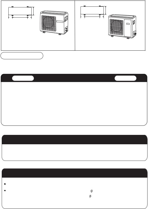
Drawing for the installation of indoor and outdoor units
|
Accessory parts |
|
|
|
|
5cm |
|
|
|
|
|
than |
|
|
|
Number |
|
|
|
|
No. |
Accessory parts |
|
|
|
more |
|
of |
|
|
|
|||
|
|
articles |
|
|
|
|
1 |
Remote controller |
1 |
|
|
e tha |
|
|
|
Optional parts for piping |
mor |
n 10c |
||
|
|
|
|
|
|
m |
2 |
|
2 |
Mark |
Parts name |
|
|
R-03 dry battery |
A |
Non-adhesive tape |
|
|
||
|
|
|
|
|
||
BAdhesive tape
3 |
1 |
C |
Saddle(L.S) with screws |
|
|
||
Mounting plate |
|
D |
Connecting electric cable |
|
|
for indoor and outdoor |
|
|
1 |
|
|
4 |
E |
Drain hose |
Drain hose
FHeating insulating material
5 |
|
4X50 |
6 |
G |
Piping hole cover |
|
|
|
Steel nail, cement |
|
|
|
|||||
|
|
|
|
|
|
|
||
6 |
4X25 |
Plastic cap |
4 |
|
|
|
|
|
|
Screw |
|
|
|
|
|
|
|
|
|
|
|
|
|
|
|
|
7 |
|
Cover |
1 |
|
|
|
|
|
8 |
|
Cushion |
4 |
|
Arrangement of piping directions |
m |
|
|
|
|
|
|
|
||||
|
|
Rear left |
|
oreth |
|
|||
|
|
|
|
|
|
an |
1 |
|
|
|
|
|
|
|
|
|
0c |
|
|
|
|
|
Left |
Rear |
|
m |
|
|
|
|
|
|
|
||
9 |
|
|
1 |
|
|
right |
|
|
Pipe supporting plate |
|
|
Right |
|
|
|||
|
|
|
|
|
Below |
|
|
|
10 |
|
|
1 |
|
|
|
|
|
Drain-elbow |
|
|
|
|
|
|||
|
an60cm |
eth |
|
mor |
|
more than 10cm
Attention must be paid to the rising up of drain hose
A
C
|
|
|
|
m |
|
|
|
c |
|
|
|
|
10 |
|
|
|
n |
|
|
|
a |
|
|
|
|
th |
|
|
|
|
re |
|
|
|
o |
|
|
|
|
m |
|
|
|
|
D
E
m |
|
ore |
|
th |
|
an |
|
15 |
cm |
|
 The marks from A to G in the figure are the parts numbers.
 The distance between the indoor unit and the floor should be more than 2m.
No.0010518785
6 . 334
113.5 |
633 |
113.5 |
Floor fixing dimensions of the outdoor unit (Unit:mm)
PAS24L03-N(T3) HSU-24HEA03(T3) HSU-24LEA03(T3) HSU-24HEA13(T3) HSU-24LEA13(T3)
Fixing of outdoor unit
0 8 3
184.3 |
580 |
184.3 |
Floor fixing dimensions of the outdoor unit (Unit:mm)
HSU-32LEA13-W
AMS30H03-N(T3)
HSU-24LEA03-T
HSU-30HEA13(T3)
HSU-30HEA03(T3)
 Fix the unit to concrete or block with bolts(
  10mm) and nuts firmly and horizontally.
  When fitting the unit to wall surface, roof or rooftop, fix a supporter surely with nails or wires in consideration of earthquake and strong wind.
 If vibration may affect the house, fix the unit by attaching a vibration-proof mat.
Indoor Unit |
Selection of Installation Place Outdoor Unit |
 Place, robust not causing vibration, where the body can be supported sufficiently.
 Place, not affected by heat or steam generated in the vicinity, where inlet and outlet of the unit are not disturbed.
 Place, possible to drain easily, where piping can be connected with the outdoor unit.
 Place, where cold air can be spread in a room entirely.
 Place, nearby a power receptacle, with enough space around. (Refer to drawings).
 Place where the distance of more than lm from televisions, radios, wireless apparatuses and fluorescent lamps can be left.
 In the case of fixing the remote controller on a wall, place where the indoor unit can receive signals when the fluorescent lamps in the room are lightened.
 Place, which is less affected by rain or direct sunlight and is sufficiently ventilated.
 Place, possible to bear the unit, where vibration and noise are not increased.
 Place, where discharged wind and noise do not cause a nuisance to the neighbors.
 Place, where a distance marked
  is available as illustrated in the above figure.
Power Source
 Before inserting power plug into receptacle, check the voltage without fail. The power source is the same as the corresponding name plate.
 Install an exclusive branch circuit of the power.
 A receptacle shall be set up in a distance where the power cable can be reached. Do not extend the cable by cutting it.
Selection of pipe
To this unit, both liquid and gas pipes shall be insulated |
|
|
|
For 24 30 32 |
|
as they become Iow temperature in operation. |
|
|
|
||
|
|
|
|
||
Use optional parts for piping set or pipes covered with |
Liquid pipe |
( |
) |
9.52mm(3/8") |
|
equivalent insulation material. |
|
|
|
|
|
Gas pipe |
( |
) |
15.88mm(5/8") |
||
|
2
,QGRRU XQLW
,QGRRU XQLW
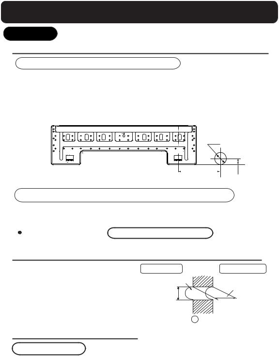
)LWWLQJ RI WKH 0RXQWLQJ 3ODWH DQG 3RVLWLRQLQJ RI WKH ZDOO +ROH
:KHQ WKH PRXQWLQJ SODWH LV ILUVW IL[HG
&DUU\ RXW EDVHG RQ WKH QHLJKERULQJ SLOODUV RU OLQWHOV D SURSHU OHYHOLQJ IRU WKH SODWH WR EH
IL[HG DJDLQVW WKH ZDOO WKHQ WHPSRUDULO\ IDVWHQ WKH SODWH ZLWK RQH VWHHO QDLO0DNH VXUH RQFH PRUH WKH SURSHU OHYHO RI WKH SODWH E\ KDQJLQJ D WKUHDG ZLWK D ZHLJKW IURP
WKH FHQWUDO WRS RI WKH SODWH WKHQ IDVWHQ VHFXUHO\ WKH SODWH ZLWK WKH DWWDFKPHQW VWHHO QDLO)LQG WKH ZDOO KROH ORFDWLRQ $ XVLQJ D PHDVXULQJ WDSH
%  PP
PP
$ PP
PP
:KHQ WKH PRXQWLQJ SODWH LV IL[HG VLGH EDU DQG OLQWHO
 )L[ WR VLGH EDU DQG OLQWHO D PRXQWLQJ EDU :KLFK LV VHSDUDWHO\ VROG DQG WKHQ IDVWHQ
WKH SODWH WR WKH IL[HG PRXQWLQJ EDU
5HIHU WR WKH SUHYLRXV DUWLFOH :KHQ WKH PRXQWLQJ SODWH LV ILUVW IL[HG IRU WKH SRVLWLRQ RI ZDOO KROH
0DNLQJ D +ROH RQ WKH :DOO DQG )LWWLQJ WKH 3LSLQJ +ROH &RYHU
 0DNH D KROH RI PP LQ GLDPHWHU VOLJKWO\ GHVFHQGLQJ WR RXWVLGH WKH ZDOO
 ,QVWDOO SLSLQJ KROH FRYHU DQG VHDO LW
RII ZLWK SXWW\ DIWHU LQVWDOODWLRQ
,QGRRU VLGH |
:DOO KROH |
PP |
2XWGRRU VLGH
7KLFNQHVV RI ZDOO
6HFWLRQ RI ZDOO KROH * 3LSLQJ KROH SLSH
,QVWDOODWLRQ RI WKH ,QGRRU 8QLW
'UDZLQJ RI SLSH
> 5HDU SLSLQJ @
 'UDZ SLSHV DQG WKH GUDLQ KRVH WKHQ IDVWHQ WKHP ZLWK WKH DGKHVLYH WDSH
> /HIW  /HIW UHDU SLSLQJ @
 ,Q FDVH RI OHIW VLGH SLSLQJ FXW DZD\ ZLWK D QLSSHU WKH OLG IRU OHIW SLSLQJ
  ,Q FDVH RI OHIW UHDU SLSLQJ EHQG WKH SLSHV DFFRUGLQJ WR WKH SLSLQJ GLUHFWLRQ WR WKH PDUN RI KROH IRU OHIW UHDU SLSLQJ ZKLFK LV PDUNHG RQ KHDW LQVXODWLRQ PDWHULDOV
 Loading...