


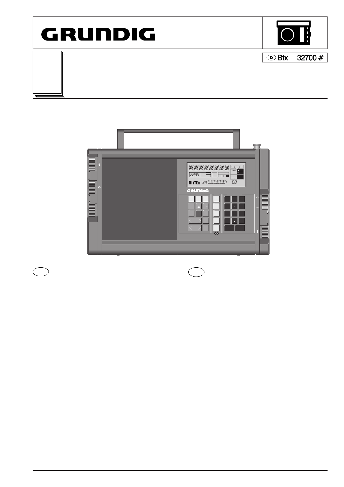
Satellit 700
Service
Manual
Satellit 700
Satellit 700 (9.15055-8151) / Satellit 700 USA (9.15055-7151) / Satellit 700 GB (9.15055-6251) / Satellit 700 Italia (9.15055-6151)
Änderungen vorbehalten Printed in Germany Service Manual Sach-Nr. 72010-719.55
Subject to alteration VK 225 1291 Service Manual Part No. 72010-719.55
*
SERVICE MANUAL
AGC MGC
LC DATA MONITOR
MODE CALL
DIRECT-KEY-INPUT
RADIO-DATA-SYSTEM
R•D•S
WORLD RECEIVER
EXCHANGEABLE MEMORY FILES COPY FUNCTION
700
+
-
+
-
+
-
VOLUME
TUNING
TIME II
AUTO
ROM
TABLE
MEMOFILE
1 2 3 4
MONO
ACCU
MGC
EXT
LOC
LSB
USB
SYNCH
MHz
R D S
kHz
MEMORY
m
0 1 2 3 4 5
TUNING
BATT./ACCU
123
456
789
0
AM
AUTO
FREE
TIME
I/II
USB
LSB
MENU
A-Z
0-9
MEMORY
FILE
MEMORY
SCAN
SEARCH
SELECT
SATELLIT
STEREO
SLEEP
FREQUENCY
m-BAND
MEMO
AF
ON/OFF
FM/
RDS-AF
MONO
STORE
SYNCH
SLEEP
CL
Inhaltsverzeichnis
Seite
Technische Daten ........................................................................... 2
Allgemeine Hinweise:
Sicherheitshinweise ............................................................... 3-5
Sicherheitshinweise zu Lithiumbatterien .................................. 5
Chip-Technik ......................................................................... 6-7
Behandlung von MOS-Bauteilen ........................................... 7-8
Ausbauhinweise ......................................................................... 9-10
Hinweise zum Satellit 700:
Spannungsversorgung ........................................................... 11
Autom. Steuerung eines Cassettengerätes ............................ 12
Befestigen des Gerätes .......................................................... 12
Memofiles ............................................................................... 12
Lautsprecher-Buchse ............................................................. 12
Synchrondetektor ................................................................... 13
RDS-Testmode ....................................................................... 13
Testmode ...................................................................................... 14
Abgleich ................................................................................... 15-18
Schaltbilder:
HF-Platte ........................................................................... 23-26
Prozessorplatte.................................................................. 27-30
Bedienplatte....................................................................... 35-37
NF- und Potiplatte.............................................................. 38-40
Druckplattenabbildungen:
HF-Platte ........................................................................... 19-22
Prozessorplatte.................................................................. 31-32
Bedienplatte....................................................................... 33-34
NF- und Potiplatte.............................................................. 41-42
Schaltbildhinweise ........................................................................ 43
Ersatzteilliste ............................................................................ 44-52
Contents
Page
Specification.................................................................................... 2
General Notes:
Safety Requirements ............................................................. 3-5
Safety Cautions for Lithium Batteries ....................................... 5
Chip Technology.................................................................... 6-7
Handling of MOS Chip Components ..................................... 7-8
Disassembly Instructions ........................................................... 9-10
Notes for the Satellit 700:
Power Supply ......................................................................... 11
Autom. Control of a Cassette Recorder.................................. 12
Securing the Unit .................................................................... 12
Memofiles ............................................................................... 12
Loudspeaker Socket ............................................................... 12
Synchronous Demodulator ..................................................... 13
RDS-Testmode ....................................................................... 13
Testmode ...................................................................................... 14
Alignment ................................................................................. 15-18
Circuit Diagrams:
RF Board ........................................................................... 23-26
Processor Board ................................................................ 27-30
Operating Board ................................................................ 35-37
AF- and Potentiometer Board ............................................ 38-40
Illustration of Printed Boards:
RF Board ........................................................................... 19-22
Processor Board................................................................31-32
Operating Board ................................................................ 33-34
AF- and Potentiometer Board ............................................ 41-42
Notes for the Circuit Diagram........................................................ 43
List of Spare Parts ................................................................... 44-52
D
GB

Specification
Power supply requirement
- From batteries:
4 x 1.5 V"HP 2" (IEC LR20) or 4 commercially available 4 Ah
accumulators of the same size (IEC KR 35/62).
Built-in automatically recharging lithium battery for data protection.
- From external voltage supply: Mains unit NR 90 or 9-12 V DC.
Output power (Mono and Stereo) in 7.5Ω
- Mains/music power according to DIN 45324: 1 and 2 x 1,5W, resp.
- Peak power: 1 and 2 x 3W, resp.
- Sinus power on battery operation acc.to DIN 45324: 1 and 2 x 0,5W,
resp.
Batterie working hours (measured according to DIN 45314)
Typ IEC LR 20 (Alkali-Mangan)
e.g. VARTA energy 2000 ALKALINE: ca. 90 hours.
e.g. Duracell MN 1300: ca. 110 hours.
4 Ah-Accus (IEC KR 35/62): ca. 25 hours.
Built-in aerials
- Telescopic aerial for FM and SW, ferrite rod aerial for MW and LW.
Connecting sockets for
- driving amplifier systems and for mono and stereo tape recordings;
LINE OUT (phono sockets)
- headphone with 3.5mm jack plug; 32-2000Ω
- external loudspeaker (left-hand and right-hand channel) with 3.5mm
jack plug; 8Ω
- driving external units, e.g., tape recorders (output switch jack);
potential-free relay control
- external power supply; mains unit NR 90 or 9-12V DC (5.5mm
coaxial socket)
- external aerial DIN 45325 (FM 75Ω/AM 50Ω coaxial socket for all
wavebands).
Wavebands
FM: 87.5 - 108 MHz
SW: 1612 - 30000 kHz
3950 - 26100 kHz (Satellit Italia)
MW:528 - 1611 kHz
LW: 150 - 353 kHz
150 - 302 kHz (Satellit Italia)
Receivable SW Bands
Band Frequency (kHz)
160-m-amateur 1815 - 1890 (not on Satellit Italia)
120-m-radio 2300 - 2498 (not on Satellit Italia)
90-m-tropic 3200 - 3400 (not on Satellit Italia)
80-m-amateur 3500 - 3800 (not on Satellit Italia)
75-m-radio 3900 - 4000
60-m-tropic 4750 - 5060
49-m-radio 5950 - 6200
41-m-radio 7100 - 7300
40-m-amateur 7000 - 7099
31-m-radio 9500 - 9900
30-m-amateur 10100 - 10150
25-m-radio 11650 - 12050
22-m-radio 13600 - 13800
20-m-amateur 14000 - 14350
19-m-radio 15100 - 15600
17-m-amateur 18065 - 18170
16-m-radio 17550 - 17900
15-m-amateur 21000 - 21449
13-m-radio 21450 - 21850
12-m-amateur 24890 - 24990
11-m-radio 25650 - 26100
10-m-amateur 28000 - 29700 (not on Satellit Italia)
IF:
FM = 10,7 MHz
AM: IF 1 = 54,5 MHz, IF 2 = 450 kHz
Technische Daten
Spannungsversorgung
- Durch Batterien:
4 x 1,5 V-Monozellen (IEC LR20) oder 4 x handelübliche 4 Ah-Akkus
in gleicher Größe (IEC KR 35/62).
Eingebaute, sich automatisch wiederaufladende Lithiumbatterie für
Datensicherung.
- Externe Versorgung: Netzteil NR 90 oder Gleichspannung 9-12 V=
Ausgangsleistung (Mono und Stereo) an 7,5Ω
- Netz-/Musikleistung nach DIN 45324: 1 bzw. 2 x 1,5W
- Spitzenleisung: 1 bzw. 2 x 3W
- Sinusleistung bei Batteriebetrieb nach DIN 45324: 1 bzw. 2 x 0,5W
Batterie-Betriebsstunden (gemessen nach DIN 45314)
Typ IEC LR 20 (Alkali-Mangan)
z.B. VARTA energy 2000 ALKALINE: ca. 90 Std.
z.B. Duracell MN 1300: ca. 110 Std.
4 Ah-Accus (IEC KR 35/62): ca. 25 Std.
Eingebaute Antennen
- Teleskopantenne für UKW und Kurzwelle, Ferritstab-Antenne für
MW und LW
Anschlußbuchsen
- zum Ansteuern von Verstärkeranlagen und für Mono- und Stereo-
Überspielungen (Aufnahmen); LINE OUT (Cinch-Buchsen)
- für Kopfhörer mit 3,5-mm-Klinkenstecker; 32-2000Ω
- für Außenlautsprecher (linker und rechter Kanal) mit 3,5-mm-Klinken-
stecker; 8Ω
- zum Steuern externer Geräte, z.B. Bandgeräte (Schaltausgangs-
Buchse) potentialfreie Relaisansteuerung
- für externe Spannungsversorgung; Netzteil NR 90 oder Gleich-
spannung 9-12V (5,5mm-Koaxial-Buchse)
- für Außenantenne DIN 45325 (FM 75Ω/AM 50Ω-Koaxial-Buchse für
alle Bereiche)
Empfangsbereiche
FM: 87,5 - 108 MHz
SW: 1612 - 30000 kHz
3950 - 26100 kHz (Satellit Italia)
MW:528 - 1611 kHz
LW: 150 - 353 kHz
150 - 302 kHz (Satellit Italia)
Empfangbare KW-Bänder
Band Frequenz (kHz)
160-m-Amateur 1815 - 1890 (nicht bei Satellit Italia)
120-m-Rundfunk 2300 - 2498 (nicht bei Satellit Italia)
90-m-Tropen 3200 - 3400 (nicht bei Satellit Italia)
80-m-Amateur 3500 - 3800 (nicht bei Satellit Italia)
75-m-Rundfunk 3900 - 4000
60-m-Tropen 4750 - 5060
49-m-Rundfunk 5950 - 6200
41-m-Rundfunk 7100 - 7300
40-m-Amateur 7000 - 7099
31-m-Rundfunk 9500 - 9900
30-m-Amateur 10100 - 10150
25-m-Rundfunk 11650 - 12050
22-m-Rundfunk 13600 - 13800
20-m-Amateur 14000 - 14350
19-m-Rundfunk 15100 - 15600
17-m-Amateur 18065 - 18170
16-m-Rundfunk 17550 - 17900
15-m-Amateur 21000 - 21449
13-m-Rundfunk 21450 - 21850
12-m-Amateur 24890 - 24990
11-m-Rundfunk 25650 - 26100
10-m-Amateur 28000 - 29700 (nicht bei Satellit Italia)
ZF:
FM = 10,7 MHz
AM: ZF 1 = 54,5 MHz, ZF 2 = 450 kHz
Technische Daten / Specification
Satellit 700
2 GRUNDIG Service-Technik
Safety Standard Compliance
After service work on a product conforming to the Safety Class II, the
insulating resistance and the leakage current with the product switch
on must be checked according to VDE 0701 or to the specification valid
at the installation location!
This product conforms to the Safety Class II, as identified by the
symbol g .
We recommend that the measurements are carried out using the
METRATESTER 3/4. (Test equipment for checking electrical products
to VDE 0701).
Metrawatt GmbH
Geschäftsstelle Bayern
Triebstr. 44
D 8000 München 50
If the safety of the product is not proved, because
- a repair and restoration is impossible
- or the request of the user is that the restoration is not to be carried
out,
the operator of the product must be warned of the danger by a written
warning.
Recommendation for service repairs
• Use only original spare parts.
With components or assemblies accompanied with the Safety
Symbol S only original-spare parts are strictly to be used.
• Use only original fuse value.
• Safety compliance, parts of the product must not be visually
damaged or unsuitable. This is valid especially for insulators and
insulating parts.
• Mains leads and connecting leads should be checked for external
damage before connection. Check the insulation!
• The functional safety of the tension relief and bending protection
bushes are to be checked:
• Thermally loaded solder pads are to be suck off and re-soldered.
• Ensure that the ventilation slots are not obstructed.
GB
Sicherheitsbestimmungen
Nach Servicearbeiten ist bei Geräten der Schutzklasse II die Messung
des Isolationswiderstandes und des Ableitstromes bei eingeschalte-
tem Gerät nach VDE 0701 / Teil 200 bzw. der am Aufstellort geltenden
Vorschrift, durchzuführen!
Dieses Gerät entspricht der Schutzklasse II, erkennbar durch das
Symbol g .
Wir empfehlen die Messungen mit dem METRATESTER 3/4 durch-
zuführen. (Meßgerät zur Prüfung elektrischer Geräte nach VDE
0701).
Metrawatt GmbH
Geschäftsstelle Bayern
Triebstr. 44
D 8000 München 50
Ist die Sicherheit des Gerätes nicht gegeben, weil
- eine Instandsetzung unmöglich ist
- oder der Wunsch des Benützers besteht, die Instandsetzung nicht
durchführen zu lassen,
so muß dem Betreiber die vom Gerät ausgehende Gefahr schriftlich
mitgeteilt werden.
Empfehlungen für den Servicefall
• Nur Original - Ersatzteile verwenden.
Bei Bauteilen oder Baugruppen mit der Sicherheitskennzeichnung
S sind Original - Ersatzteile zwingend notwendig.
• Auf Sollwert der Sicherungen achten.
• Zur Sicherheit beitragende Teile des Gerätes dürfen weder beschä-
digt noch offensichtlich ungeeignet sein.
• Dies gilt besonders für Isolierungen und Isolierteile.
• Netzleitungen und Anschlußleitungen sind auf äußere Mängel vor
dem Anschluß zu prüfen. Isolation prüfen!
• Die Funktionssicherheit der Zugentlastung und von Biegeschutz-
Tüllen ist zu prüfen.
• Thermisch belastete Lötstellen absaugen und neu löten.
• Belüftungen frei lassen.
D
Attention: Priere d`observer les prescriptions de securite
VDE 701 (concernant les reparations) et VDE 0860 / IEC 65
(concernant le type de produit)!
Composants répondant aux normes VDE ou IEC. Les rem-
placer uniquement par des composants ayant les memes
spécifications.
Lors de la manipulation des circuits MOS, respecter les
pescriptions MOS!
Atención: Recomendamos las normas de seguridad VDE u
otras normas equivalentes, por ejemplo: VDE 701 para
reparaciones, VDE 0860 / IEC 65 para aparatos!
Componentes que cumplen las normas VDE/IEC. En caso
de sustitución, emplear componentes con idénticas especi-
ficaciones!
Durante la reparacion observar las normas sobre com-
ponentes MOS!
Attention: This set can only be operated from AC mains of
120 V/60 Hz. Also observe the information given on the rear
of the set.
CAUTION-for continued protection against risk of fire re-
place only with same type fuses!
CAUTION: to reduce the risk of electric shock, do not remove
cover (or back), no user-serviceable parts inside, refer
servicing to qualified service personnel. Observe MOS
components handling instructions when servicing!
Achtung: Bei Eingriffen ins Gerät sind die Sicherheitsvor-
schriften nach VDE 701 (reparaturbezogen) bzw. VDE 0860
/ IEC 65 (gerätebezogen) zu beachten!
Bauteile nach IEC- bzw. VDE-Richtlinien ! Im Ersatzfall nur
Teile mit gleicher Spezifikation verwenden!
MOS - Vorschriften beim Umgang mit MOS - Bauteilen
beachten!
Attention: Please observe the applicable safety require-
ments according to VDE 701 (concerning repairs) and VDE
0860 / IEC 65 (concerning type of product)!
Components to IEC or VDE guidelines! Only use compo-
nents with the same specifications for replacement!
Observe MOS components handling instructions when ser-
vicing!
Attenzione: Osservarne le corrispondenti prescrizioni di
sicurezza VDE 701 (concernente servizio) e VDE 0860 / IEC
65 (concernente il tipo di prodotto)!
Componenti secondo le norme VDE risp. te IEC! In caso di
sostituzione impiegare solo componenti con le stesse carat-
teristiche.
Osservare le relative prescrizioni durante, lavori con compo-
nenti MOS!
V
D E
!
!
!
V
D E
V
D E
!
V
D E
V
D E
!
!
U.S.&
Canada
USA
D
GB
I
F
E
Sicherheitsvorschriften/Safety requirements/Prescrizioni de sicurezza/Prescriptions de sécurité/
Prescripciones de seguridad
Allgemeine Hinweise General Notes
Satellit 700 Allgemeine Hinweise / General Notes
GRUNDIG Service-Technik
3
DISPOSICIONES PARA LA SEGURIDAD
Después de operaciones de servicio en aparatos de la clase de
proteccion II, se llevará a cabo la medida de la resistencia de
aislamiento y de la corriente derivada, con el aparato conectado, de
acuerdo con VDE 0701 o de las disposiciones vigentes en el lugar de
instalación .
Este aparato corresponde a la clase de protección II, reconocible por
el sìmbolo g .
Aconsejamos llevar a cabo las medidas con el METRATESTER 3/4
(Instrumento de medida para la comprobación de aparatos eléctricos
según VDE 0701).
METRAWATT GmbH
Geschäftsstelle Bayern
Triebstr. 44
D 8000 München 50
Si no se cumple la seguridad del aparato, porque
- la puesta en orden es imposible, o
- esiste el desco del usuario de no realizarla, se ha de comunicar a
quien lo haga funcionar, por escrito, del peligro dimanante del
aparato.
Recomendaciones para caso de servicio
• Emplear sólo componentes originales.
Con componentes o grupos constructivos con el indicativo de se
guridad S son de obligada necesidad piezas de repuesto origina-
les.
• Las partes del aparato que contribuyan a la seguridad del mismo no
deben estar deterioradas ni ser manifiestamente inadecuadas.
• Esto es especialmente válido para aislamientos o piezas aislantes.
• Los cables de red y de conexión se comprobarán, antes de concc
tarlos, en cuanto a defectos externos. Comprobar el aislamiento.
• Se ha de comprobar la función de seguridad de la compensación de
tiro o de los manguitos de protección contra doblamientos.
• Repasar los puntos de soldadura sometidos a carga térmica.
• Mantener libres los canales aireación.
E
Norme di sicurezza
Successivamente ai lavori di riparazione, negli apparecchi della classe
di protezione II occorre effettuare la misura della resistenza di
isolamento e della corrente di dispersione quando l’apparecchio
e’acceso, secondo le norme VDE 0701 / parte 200 e rispettivamente
le norme locali!
Questo apparecchio corrisponde alla classe di protezione II ed è
riconoscibile dal simbolo g .
Si raccomanda di effettuare le misure con lo strumento METRA–
TESTER 3/4 (strumento di misura per il controllo di apparecchi elettrici
secondo VDE 0701).
Metrawatt GmbH
Geschäftsstelle Bayern
Triebstr. 44
D 8000 München 50
Se la sicurezza dell’apparecchio non è raggiunta, perchè
- una riparazione non è possibile
- oppure è desiderio del cliente che una riparaz. non avvenga in questi
casi si deve comunicare per iscritto all’utilizzat.
la pericolosità dell’apparecchio riguardo il suo isolamento.
Raccomandazione per il servizio assistenza MM
• Impiegare solo componenti originali:
I componenti o i gruppi di componenti contraddistinti dall’ indicaz.
S devono assolutamente venir sostituiti con parti originale.
• Osservare il valore nominale dei fusibili.
• I componenti che concorrono alla sicurezza dell´apparecchio non
possono essere nè danneggiati nè risultare visibilmente inadatti.
Questo vale soprattutto per isolamenti e parti isolate.
• I cavi di rete e di collegamento vanno controllati prima dell’utilizzo
affinchè non presentino imperfezioni esteriori. Controllare l’isola
mento.
• E´necessario controllare la sicurezza dei fermacavi e delle guaine
flessibili.
• Saldature caricate termicam. vanno rifatte.
• Lasciare libere le fessure di areazione.
I
Prescriptions de securite
Suite aux travaux de maintenance sur les appareils de la classe II, il
convient de mesurer la résistance d’isolement et le courant de fuite sur
l’appareil en état de marche, contormément á la norme VDE 0701 §
200, ou selon les prescriptions en vigueur sur le lieu de fonctionnement
de l’appareil!
Cet appareil est conforme aux prescriptions de sécurité classe II,
signaléé par le symbole g .
Pour ces mesures, nous préconisons l´utilisation du METRA–TE-
STER 3/4 (instrument de mesure pour le contrôle d’appareils électri-
ques conformes á la norme VDE 0701).
METRAWATTWATT GmbH
Geschäftsstelle Bayern
Triebstr. 44
D 8000 München 50
Dans le cas où la sécurité de l’appareil n´est pas assurée pour les
aisons suivantes:
- la remise en état est impossible
- l’utilisateur ne souhaîte pas la remise en état de l’appareil.
l’utilisateur doit être informé par écrit du danger que représente lùtili
sation de l’appareil.
Recommandations pour la maintenance
• Utiliser exclusivement des piéces de rechange d’origine. Les
composants et ensembles de composants signalés par le symbole
S doivent être impérativement remplacés par des pièces d’origine.
• Respecter la valeur nominale des fusibles.
• Veiller au bon état et la conformité des pièces contribuant à la
sécurité de fonctionnement de l’appareil. Ceci s’applique particulié-
rement aux isolements et pièces isolantes.
• Véritier le bon état extérieur des câbles secteur et des câbles de
raccordement au point de vue isolement avant la mise sous tènsion.
• Véritier le bon état des protections de gaine.
• Nettoyer les soudures avant de les renouveler.
• Dégager les voies d’aération.
F
Allgemeine Hinweise / General Notes
Satellit 700
4 GRUNDIG Service-Technik
Safety Instructions
The lightning flash with arrowhead symbol, within an equilate-
ral triangle, is intended to alert the user to the presence of
uninsulated "dangerous voltage", within the product´s enclo-
sure that may be of sufficient magnitude to constitute a risk of
electric shock to persons.
The exclamation point within an equilateral triangle is intended
to alert the user to the presence of important operating and
maintenance (servicing) instructions in the literature accom-
panying the appliance.
This product was designed and manufactured to meet
strict quality and safety standards. There are, however,
some installation and operation precautions which you
should be particularly aware of.
• Read Instructions - All the safety and operating instructions
should be read before the appliance is operated.
• Retain Instructions - The safety and operating instructions
should be retained for future reference.
• Heed Warnings - All warnings on the appliance and in the
operating instructions should be adhered to.
• Follow Instructions - All operating and use instructions should
be followed.
• Water and Moisture - The appliance should not be used near
water-for example, near a bathtub, washbowl, kitchen sink,
laundry tub, in a wet basement, or near a swimming pool, and
the like.
• Wall or Ceiling Mounting - The appliance should be mounted
to wall or ceiling only as recommended by the manufacture.
• Ventilation - The appliance should be situated so that its
location or position does not interfere with its proper
ventilation. For example, the appliance should not be situated
on a bed, sofa, rug, or similar surface that may block the
ventilation openings; or, placed in a built - in installation, such
as a bookcase or cabinet that may impede the flow of air
through the ventilation openings.
• Heat - The appliance should be situated away from heat
sources such as radiators, heat registers, stoves, or other
appliances (including amplifiers) that produce heat.
• Power Sources - The appliance should be connected to a
power supply only of the type given above or as marked on the
appliance.
• Power-Cord Protection - Power-supply cords should be routed
so that they are not likely to be walked on or pinched by items
placed upon or against them, paying particular attention to
cords at plugs, convenience receptacles, and the point where
they exit from the appliance.
• Cleaning - The appliance should be cleaned only as recom-
men ded by the manufacturer.
• Power Lines - An outdoor antenna should be located
x1 away from power lines.
• Outdoor Antenna Grounding - If an outside antenna is
x2 connected to the receiver, be sure the antenna system is
grounded so as to provide some protection against voltage
surges and built up static charges. Section 810 of the National
Electrical Code, ANSI / NFPA No. 70-1984, provides informa-
tion with respect to proper grounding of the mast and suppor-
ting structure, grounding of the lead-in wire to an antenna
discharge unit, size of grounding conductors, location of
antenna discharge unit, connection to grounding electrodes,
and requirements for the grounding electrode.
• Nonuse Periods - The power cord of the appliance shold be un
plugged from the outlet when left unused for a long period
of time.
• Object and Liquid Entry - Care should be taken so that objects
do not fall and liquids are not spilled into the enclosure through
openings.
• Damage Requiring Service - The appliance should be servi-
ced by qualified service personnel when: The power-supply
cord or the plug has been damaged; or objects have fallen,
or liquid has bee spilled into the appliance; or the appliance
has been exposed to rain; or the appliance does not appear to
operate normally or exhibits a marked change in performan-
ce; or the appliance has been dropped, or the enclosure
damaged; or the batteries have been damaged.
• Servicing - the user should not attempt to service the appliance
beyond that described in the operating instructions. All other
servicing should be referred to qualified service personnel .
Items x1 and x2 apply only to receivers or tuners.
!
!
d
Sicherheitshinweise zu Lithium-Batterien
Vorsicht bei Lithium-Batterien:
Bei falscher Handhabung (Überhitzung, Falschpolung oder Kurz-
schluß) der Lithium-Batterien besteht Explosionsgefahr!
Lithium-Batterien dürfen nur gegen Original-Ersatzteile (s. Ersatz-
teilliste) getauscht werden.
©ü
Safety cautions for Lithium Batteries
Warning! Lithium Batteries:
Wrongly used lithium batteries (excessive heat, wrong connection of
terminals, short circuit) represent a danger of explosion!
Lithium batteries must be replaced only by original spare parts (see
Spare Parts List).
Please observe the appropriate disposal regulations for exhausted
lithium batteries.
#
Varning
Eksplosionsfara vid felaktigt batteribyte. Ånvänd samma batterityp
eller en ekvivalent typ som rekommenderas av apparattillverkaren.
Kassera använt batteri enligt fabrikantens instruktion.
<
Varoitus
Paristo voi räjähtää, jos se on virheellisesti asennettu.
Vaihda paristo ainoastaan laitevalmistajan suosittelemaan tyyppiin.
Hävitä käytetty paristo valmistajan ohjeiden mukaisesti.
y
Advarsel!
Lithiumbatteri - eksplosionsfare ved fejlagtig håndtering. Udskiftning
må kun ske med batteri af samme fabrikat og type.
Levér det brugte batteri til de offentlige indsamlingssteder.
Udskiftning må kun foretages af en sagkyndig, og som beskrevet in
servicemanualen.
Satellit 700 Allgemeine Hinweise / General Notes
GRUNDIG Service-Technik
5
ü
U.S.&
Canada
U.S.&
Canada
Pinzette
Tweezers
Pinzetta
Pince brucelle
Pinzas
Lötkolbenspitze
Tip of soldering iron
Punta saldatore
Panne du fer à souder
Punto de soldator
D
CHIP Technik
Aus- und Einlöten von CHIP-Bauteilen
- Verwenden Sie nur einen Niedervoltlötkolben mit Temperatur-
regelung.
- Die Löttemperatur sollte ca. 240 °C betragen (max. 300 °C).
- Halten Sie die Lötzeit so kurz wie möglich.
- Belassen Sie CHIP-Bauteile bis zur Bearbeitung in der Originalver-
packung. Damit wird die Oxidation der Stirnkontakte vermieden.
- Berühren Sie CHIP- Bauteile nicht mit der bloßen Hand.
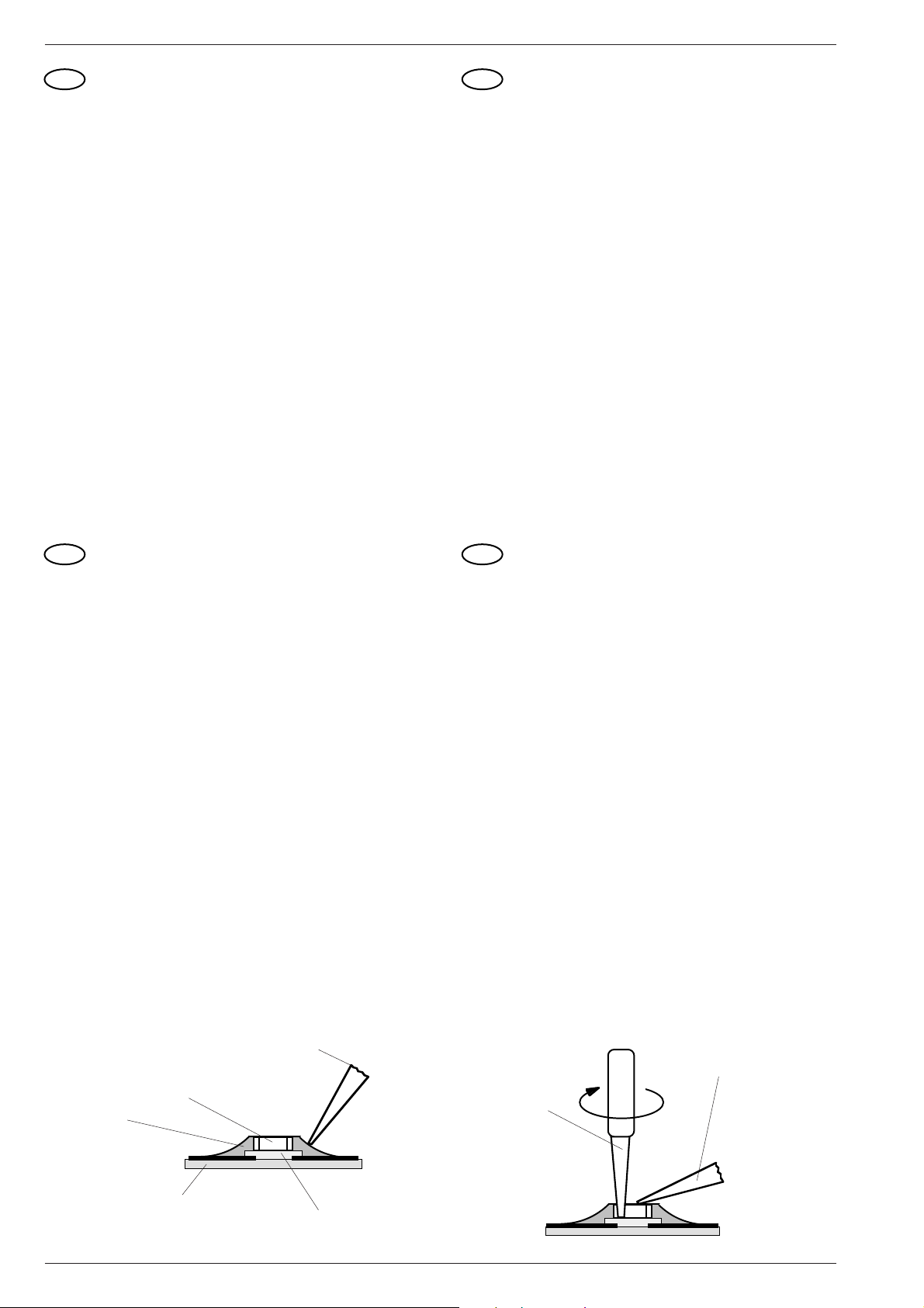
Auslöten von CHIP-Bauteilen
1. Schritt: CHIP- Lötstelle mit Sauglitze absaugen (Fig. 1).
2. Schritt: CHIP-Enden, bzw. das komplette CHIP-Bauteil erwärmen.
CHIP von der Klebung ohne Kraftaufwand abdrehen, damit
unter dem CHIP liegende Leiterbahnen nicht abgerissen
werden (Fig. 2).
Achtung!
Ausgelötetes CHIP nicht wiederverwenden!
Die leitende Schicht kann ausgebrochen sein.
Einlöten von CHIP-Bauteilen
3.Schritt: Lötpunkt von Lötrückständen säubern.
Lötperle anbringen (Fig. 3).
4. Schritt: CHIP an der Lötstelle ansetzen, zentrieren und anlöten
(Fig. 4).
5.Schritt: Freie Seite löten. Nach dem Erkalten die erste Lötstelle
nochmals nachlöten (Fig. 5).
I
Tecnica CHIP
Saldatura e dissaldatura di componenti MOS
- Impiegare un saldatore a basso voltaggio con regolazione della
temperatura.
- Temperatura del saldatore: ca. 240 °C (valore massimo 300 °C).
- Il tempo di saldatura deve essere il più breve possibile.
- Il componente CHIP deve rimanere nell´imballaggio originale fino al
momento del suo impiego per evitare che le superfici di contatto si
ossidino.
- Non toccare i componenti CHIP con mani nude.
Dissaldatura di un CHIP
1. Aspirare i punti di saldatura del CHIP con una calza dissaldante
(Fig. 1).
2. Riscaldare le superfici di contatto del CHIP risp. te tutto il CHIP e
staccarlo con cautela. Attenzione a non esercitare for za per non
danneggiare le piste sottostanti (Fig. 2).
Attenzione!
Non impiegare più il CHIP dissaldato, perchè il corpo elettrico
può presentare delle rotture.
Saldatura di un CHIP
3. Pulire il punto dai residui di saldatura. Applicare una goccia di stagno
(Fig. 3).
4. Appoggiare il CHIP sul punto di saldatura, centrarlo e quindi saldarlo
(Fig. 4).
5. Saldare la superfici di contatto libera e, dopo che questa si è
raffreddata, saldare nuovamente la superfici opposta (Fig. 5).
GB
CHIP Technology
Soldering and unsoldering of CHIP components
- Use only low-voltage soldering irons with temperature control.
- Permissible soldering temperatures are approx. 240 °C up to
max. 300 °C.
- Keep the soldering period as short as possible.
- Keep the CHIP components in their original packages until they
are used to avoid oxidation of the end contacts.
- Do not touch CHIP components with bare hands.
Unsoldering of CHIP components
1. step: Clean the CHIP soldering point with a solder wick (Fig. 1).
2. step: Warm up the ends of the CHIP or the whole CHIP component
and remove the CHIP from the adhesive by turning it without
application of force so that the tracks beneath the CHIP do not
break (Fig. 2).
Attention!
Do not use unsoldered CHIPS any more!
The conductive layer may be broken.
Soldering of CHIP components
3. step: Remove possible residues from the soldering point.
Then apply a solder bead (Fig. 3).
4. step: Put the CHIP onto the soldering point, then center and fix it
(Fig. 4).
5. step: Solder the free end of the CHIP and resolder the first
soldering point after it has cooled (Fig. 5).
F
Technologie CMS
Soudure des composants CMS
- Utiliser exclusivement un fer à souder à basse tension et réglage
thermique
- La température de soudure doit être de 240 °C environ (max.
300 °C).
- L´opération doit être très brève.
- Conserver les composants CMS dans leur emballage d´origine
jusqu´au moment de leur utilisation, ceci pour éviter l´oxydation
des contacts externes.
- Ne pas toucher les composants CMS à la main nue.
Dessoudage des composants CMS
1. Aspirer la soudure du composant CMS à la l´aide de la tresse à
souder (Fig. 1).
2. Chauffer légèrement les contacts externes du composant CMS ou
le composant lui-même. Retirer ce dernier avec précaution en le
tournant afin d´évìter un arrachement des circuits imprimés situés
sous le composant (Fig. 2).
Attention!
Ne pas réutiliser les composants CMS, la face conductrice
pouvant être endomagée.
Soudure des composants CMS
3. Aspirer les restes de soudure sur le circuit. Poser une pointe de
soudure (Fig. 3).
4. Poser le composant CMS sur cette pointe de soudure, centrer et
souder. Maintenir le composant CMS à l´aide d´une pince brucelle
(Fig. 4).
5. Effectuer la même opération pour l´autre coté. Terminer la première
soudure (Fig. 5).
Kleber
Adhesive
Adesivo
Adhesif
Pegamento
Lötzinn
Solder
Stagno
Soudure
Estaño
Chip
Composant CMS
Lötkolbenspitze
Tip of soldering iron
Punta saldatore
Panne du fer à souder
Punto de soldator
Fig. 2
Leiterplatte
P.C.B.
Piastra stampata
Circuit imprimé
Placa de circuito impreso
Fig. 1
Allgemeine Hinweise / General Notes
Satellit 700
6 GRUNDIG Service-Technik
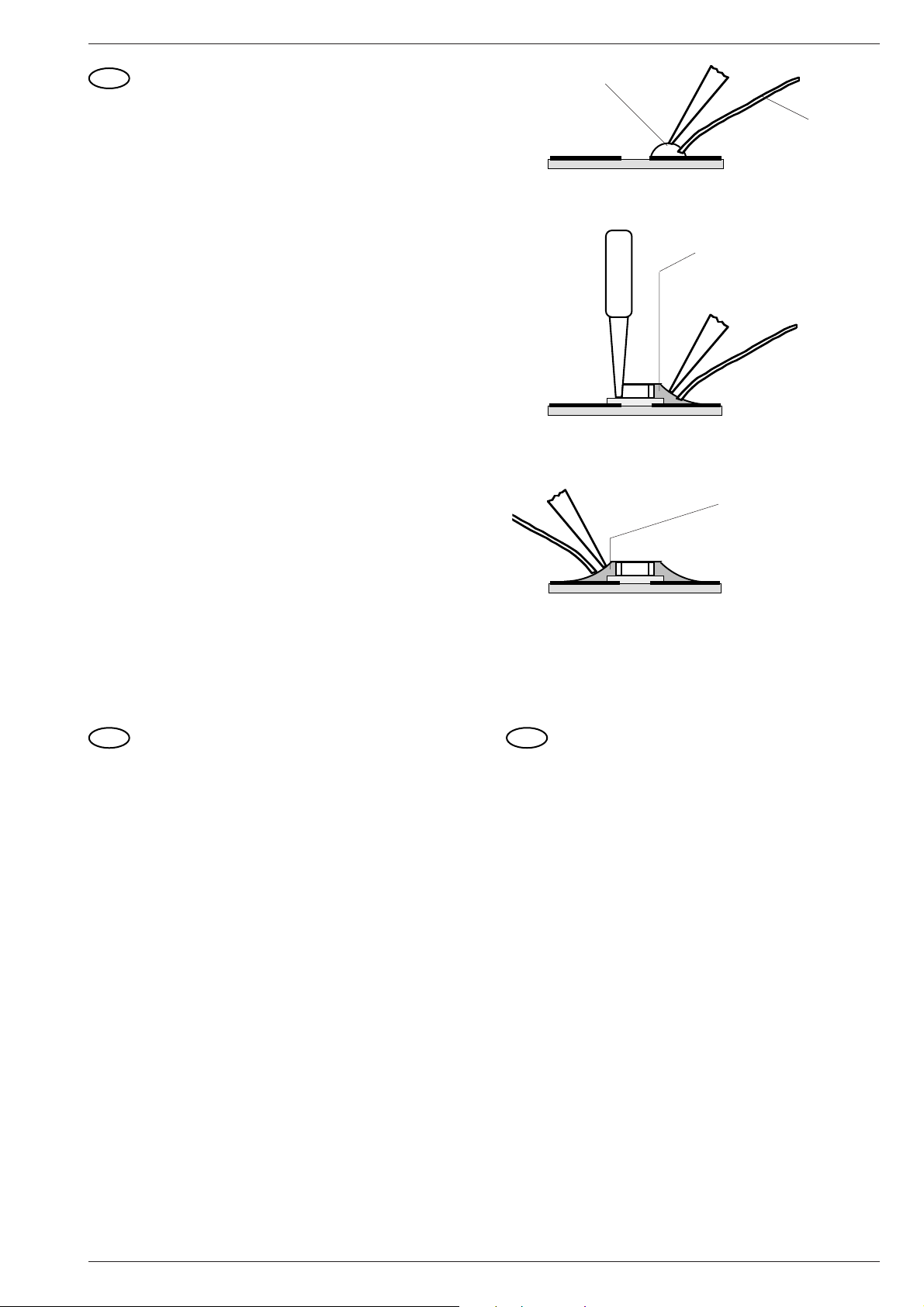
Fig. 3
Fig. 4
Fig. 5
Fixierpunkt
Fixing point
Punto di fissaggio
Point de soudure
Punto de fijación
Lötzinn
Solder
Stagno
Soudure
Estaño
2. Lötstelle
2. Joint
Punto di saldatura 2
2. point de soudure
Segunda punto de soldadura
1. Lötstelle
1. Joint
Punto di saldatura 1
1. point de soudure
Primer punto de soldadura
E
Técnica de CHIP´s
Soldaje y desoldaje de CHIP´s
- Emplear sólo un soldador de bajo voltaje con regulación de
temperatura.
- La temperatura del soldador debe ser de aprox. 240 °C
(máx. 300 °C).
- El tiempo de soldadura debe de ser lo más corto posible.
- Dejar los componentes CHIP hasta su montaje en el embalaje
original. Con ello se evita la oxidación de los contactos frontales.
- No tocar con las manos los componentes CHIP.
Desoldaje de un CHIP
Primer paso: Aspirar el estaño del punto de soldadura con un
aspirador de los tipos de pera o de resorte (Fig. 1).
Segundo paso: Calentar los extremos o todo el CHIP y girarlo con las
pinzas. No hacer fuerza para que la placa de circuito
impreso no resulte dañada. Cuidar de que las pistas
situadas debajo del CHIP no se suelten de la placa, ya
que éstas también están pegadas (Fig. 2).
Ciudado!
No volver a utilizar el CHIP desoldado. La capa eléctrica puede
estar interrumpida.
Soldadura de CHIP´s
Tercer paso: Limpiar el punto de soldadura de residuos de la
soldadura anterior. Poner una gota de estaño (Fig. 3).
Cuarto paso: Colocar el CHIP sobre la gota estaño, centrarlo y
soldarlo (Fig. 4).
Quinto paso: Soldar la parte libre y, después enfriarse, soldar
también la parte opuesta (Fig. 5).
GB
Handling of MOS Chip Components
MOS circuits require special attention with regard to static charges.
Static charges may occur with any highly insulating plastics and can be
transferred to persons wearing clothes and shoes made of synthetic
materials.
Protective circuits on the inputs and outputs of MOS circuits give
protection to a limited extent only due to the time of reaction.
Please observe the following instructions to protect the components
against damages from static charges:
1. Keep MOS components in conductive packages until they are
used. MOS components must never be stored or transported in
Styropor materials or plastic magazines.
2. Persons have to rid themselves of electrostatic charges by
touching a grounded object before handling MOS components.
3. Take the chip by the body without touching the terminals.
4. Use only grounded instruments for testing and processing
purposes.
5. Remove or connect MOS ICs with in mounting sockets only if the
operating voltage is disconnected.
6. The circuits of p-channel MOS components must not be
connected to positive voltages (with reference to bulk VSS).
MOS Soldering Instructions
• Use only mains isolated low-voltage soldering irons.
• Maximum soldering period 5 seconds at a soldering iron tempe-
rature of 300 to 400 degrees Celsius.
D
Behandlung von MOS - Bauelementen
Schaltungen in MOS-Technik bedürfen besonderer Vorsichtsmaß-
nahmen gegenüber statischer Aufladung. Statische Aufladungen kön-
nen an allen hochisolierenden Kunststoffen auftreten und auf den
Menschen übertragen werden, wenn Kleidung und Schuhe aus syn-
thetischem Material bestehen.
Schutzstrukturen an den Ein- und Ausgängen der MOS-Schaltungen
geben wegen ihrer Ansprechzeit nur begrenzte Sicherheit.
Bitte beachten Sie folgende Regeln, um Bauelemente vor Beschädi-
gung durch statische Aufladungen zu schützen:
1. MOS-Schaltungen sollen bis zur Verarbeitung in elektrisch leiten-
den Verpackungen verbleiben. Keinesfalls MOS-Bauteile in Styro-
por oder Plastikschienen lagern oder transportieren.
2. Personen müssen sich durch Berühren eines geerdeten Gegen-
standes entladen, bevor sie MOS-Bauteile anfassen.
3. MOS-Bauelemente nur am Gehäuse anfassen, ohne die Anschlüs-
se zu berühren.
4. Prüfung und Bearbeitung nur an geerdeten Geräten vornehmen.
5. Lösen oder kontaktieren Sie MOS-ICs in Steckfassungen nicht
unter Betriebsspannung.
6. Bei p-Kanal-MOS-Bauelementen dürfen keine positiven Span-
nungen (bezogen auf den Substratanschluß VSS) an die Schaltung
gelangen.
Lötvorschriften für MOS-Schaltungen:
• Nur netzgetrennte Niedervoltlötkolben verwenden.
• Maximale Lötzeit 5 Sekunden bei einer Lötkolbentemperatur von
300 °C
bis 400 °C.
Satellit 700 Allgemeine Hinweise / General Notes
GRUNDIG Service-Technik
7
I
Impiego dei componenti MOS
I circuiti in tecnica MOS necessitano di una particolare attenzione per
evitare le scariche elettrostatiche.
Tutti i materiali sintetici ad alto potere isolante possono caricar si
staticamente e queste cariche possono trasmettersi all´uomo, par
ticolarmente se scarpe o vestiti sono sintetici.
Le strutture di sicurezza sull´ingresso e sull´uscita dei circuiti MOS
hanno un´efficacia limitata a causa del loro periodo di intervento.
Per proteggere i componenti MOS dalle scariche elettrostatiche si
consigla di adottare le seguenti precauzioni:
1. Fino al momento del loro impiego, i MOS devono restare in materiale
elettricamente conduttivo. Non trasportarli o depositarli mai in listelli
di plastica o in polistirolo.
2. Le persone che maneggiano i componenti MOS devona prima
scaricar si elettrostaticamente toccando un oggetto con collega-
mento a massa.
3. Maneggiare i componenti MOS toccandone solo l´involucro e mai i
piedini.
4. Controlli e lavorazioni devono avvenire soltanto su apparecchi con
messa a terra.
5. Non inserire e non staccare mai gli integrati MOS dagli zoccoli
quando la tensione di alimentazione è collegata.
6. Ai componenti MOS canale P non devono giungere tensioni positive
(rif. a collegamento del substrato VSS).
Norme di taratura per gli integrati MOS:
• Impiegare solo saldatori a bassa tensione con separazione dalla
rete.
• Il tempo massimo di saldatura è di 5 sec. con una temperatura del
saldatore compresa fra 300 °C e 400 °C.
E
Tratamiento de componentes en técnica MOS
Los circuitos contruídos en técnica MOS precisan un cuidado especial
contra las cargas estáticas.
En todos los materiales plásticos de elevado aislamiento pueden
aparecer cargas estáticas y también ser transmitidas a la personas,
especialmente cuando las ropas y zapatos son de materia sintética.
Las estructuras de protección en las entradas y salidas de los
integrados MOS, debido a su tiempo de conexión, proporcionan sólo
una limitada seguridad.
Para proteger los módulos de las descargas estáticas es aconsejable
prestar atención a las siguientes reglas:
1. Los circuitos integrados MOS deben permanecer envueltos en un
material conductor hasts el momento de su empleo. En ningún caso
se les colocará ni transportará en recepientes de styropor o guías de
plástico.
2. Las personas que trabajan con elementos MOS deben descargarse
previamente tocando un objecto puesto a tierra.
3. Los elementos MOS sólo deben cogerse por la cápsula, sin rozar
siquiera los terminales.
4. Pruebas y trabajos con los circuitos MOS sólo deben realizarse en
aparatos que estén puestos a tierra.
5. No extraer ni establecer contacto bajo tensión de funcionamiento de
los IC´s MOS enchufables.
6. En los componentes MOS canal-p no deben llegar tensiones
positivas (con respecto a la tensión de substrato VSS) a los
circuitos.
Prescipciones para la soldadura de los circuitos integrados MOS:
• Utilizar únicamente soldadores de baja tensión con transformador-
separador de la red.
• Tiempo máximo de soldadura: 5 segundos con una temperatura
entre 300 y 400 °C.
F
Précautions à prendre pour la manipulation des
circuits MOS
Les circuits équipés en technique MOS exigent des précautions
particulières contre les charges statiques.
Des charges statiques peuvent se créer sur toutes les matières
synthétiques à fort pouvoir isolant, elles peuvent se transmettre au
corps humain et le risque est d´autant plus important si la personne
porte des vêtements ou des chaussures en matière synthétique.
Les systèmes de protection dont sont équipées les entrées et sorties
des circuits MOS n´apportent qu´une sécurité limitée du fait de leur
temps de fonctionnement.
Afin de protéger les composants contre les charges statiques, il est
recommandé d´observer les règles suivantes:
1. Les circuits MOS doivent rester placés dans un matérial conducteur
jusqu´au moment de leur utilisation. Il ne doivent en aucun cas être
stockés ou transportés dans du styropore ou sur des bandes de
plastique.
2. Les personnes travaillant sur des circuits MOS doivent au préalable
se décharger de leur charge statique en touchant un object mis à
terre.
3. Les ensembles équipés de circuits MOS doivent être saisis unique-
ment par leur boîtier, on ne doit pas toucher les broches de
raccordement.
4. On ne doit effectuer de contrôles et travaux que sur des appareils
mis à la terre.
5. Ne jamais retirer ou raccorder un circuit MOS sur un appareil sous
tension.
6. Les circuits MOS canal p ne doivent en aucun cas recevoir de
tensions positives (en VSS
par rapport à la liaison vers le substrat).
Prescription de soudure sur les circuits MOS
• N´utiliser que des fers à souder basse tension isolés du secteur
• Temps de soudure maximum : 5 secondes pour une température
comprise entre 300 °C et 400 °C.
Allgemeine Hinweise / General Notes
Satellit 700
8 GRUNDIG Service-Technik
AA
A
A
I
C
C
E
E
F
F
D
B
BU5
B
I
Ausbauhinweise Disassembly Instructions
Satellit 700
GRUNDIG Service-Technik
Ausbauhinweise / Disassembly Instructions
9
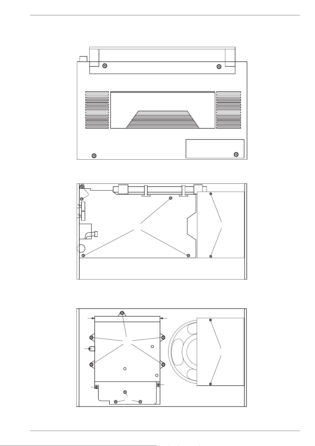
Rückwand
- 4 Schrauben A herausschrauben.
- Rückwand an der Bodenseite anheben und vorsichtig aufklappen.
Plusleitung der Batterie abziehen.
HF - Platte
- 5 Schrauben B herausschrauben.
- Steckverbindung BU5 lösen.
- HF-Platte rechts anheben.
Achtung:
Ferritantenne an der NF-Platte vorbeiführen.
HF-Platte etwas nach rechts ziehen, bis sie an der linken Seite
hochgeklappt werden kann.
In dieser Stellung ist das Gerät funktionsfähig!
- Die restlichen Steckverbindungen abziehen.
- HF-Platte herausnehmen.
Digitalbaustein
- HF - Platte ausbauen.
- Handradanschlüsse ablöten
- 8 Schrauben C herausschrauben.
- Steckverbindung zur NF-Platte lösen.
- Digitalbaustein herausnehmen.
Achtung:
Unter dem Abschirmblech ist bei D eine Feder!
Digitalbaustein öffnen
- 2 Schrauben E herausschrauben.
- 2 Halter F aufbiegen.
- Platten voneinander abziehen.
NF - Platte und Potentiometerplatte
- 3 Knöpfe G abziehen.
- 3 Muttern H abschrauben.
- 2 Schrauben I herausschrauben.
- Lautsprecherleitung ablöten.
- Steckverbindungen lösen.
- Masseleitung zum Lautsprechergitter ablöten.
- Beim Einbau darauf achten, daß der LOCK-Schalter in den
Schalterknopf eingreift.
Displaybeleuchtung
- Digitalbaustein ausbauen und öffnen.
- Displaylampen auslöten.
Rear Panel.
- Unscrew 4 screws A.
- Lift the rear panel at the bottom side and remove it carefully.
- Disconnect the battery plus wire.
RF Board
- Unscrew 5 screws B.
- Disconnect the plug-in connection BU5.
- Lift the RF board at the right side.
Attention:
Move the ferrite antenna past the AF board.
Move the RF board to the right, so that its left side can be tipped up.
In this position the unit is functionable!
- Disconnect the remaining plug-in connections.
- Remove the RF board.
Digital Unit
- Remove the RF board.
- Unsolder the connection to the hand wheel.
- Unscrew the 8 screws C.
- Disconnect the plug-in connection to the AF board.
- Remove the digital unit.
Attention:
Under the shield there is a spring at D .
Opening of the Digital Unit
- Unscrew 2 screws E.
- Bend up the 2 holders F.
- Dismantle the boards.
AF Board and Potentiometer Board
- Pull off the 3 knobs G.
- Unscrew the 3 hexagon nuts H.
- Unscrew the 2 screws I.
- Unsolder the line to the loudspeaker.
- Disconnect the plug-in connections.
- Unsolder the line to the loudspeaker grill.
- When reassembling take care that the LOCK switch engages with
its button.
Display illumination
- Remove the digital unit and open it.
- Unsolder the display lamps.
LOCKED
9-12V
+
EXT DC
L
R
LINE OUT
L
H G
Ausbauhinweise / Disassembly Instructions
Satellit 700
10 GRUNDIG Service-Technik
D
Hinweise zum Satellit 700
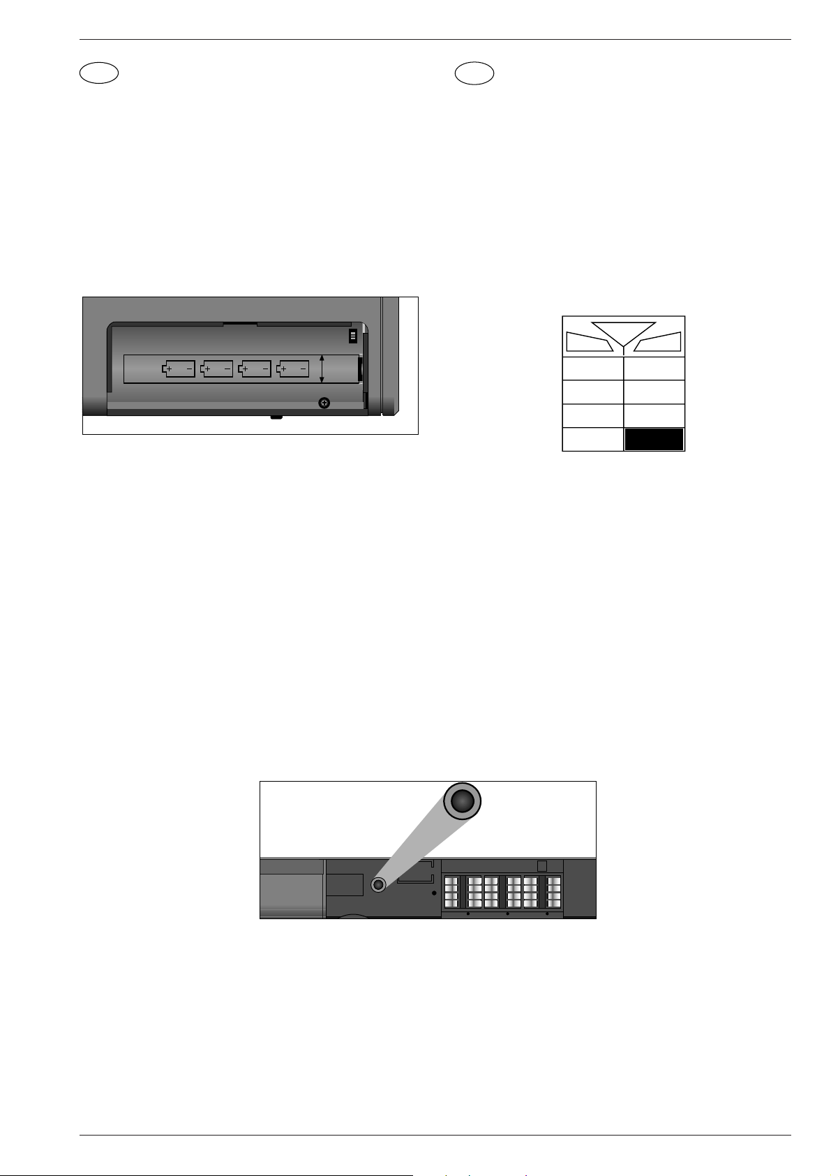
Spannungsversorgung
Batterie- bzw. Accu-Betrieb
Mit 4 Monozellen IEC LR 20 (Alkali-Mangan-Batterien) bzw. handel-
üblichen Ni Cd-Accus gleicher Größe.
- Verwenden Sie nur Accus mit dem Aufdruck 1,24V und 4000 mAh.
- Setzen Sie die Batterien bzw. Accus polarisationsrichtig ein
-
Achtung:
Bei Batteriebetrieb muß der Schiebeschalter ACCU/BATT.
(im Batteriefach) in Stellung BATT. stehen. Niemals bei eingesetz-
ten Batterien den Schalter auf ACCU stellen bzw. stehen lassen
(Anzeige ACCU).
Für Schäden, die durch unsachgemäßes Benutzen der Ladeein-
richtung entstehen, kann keine Haftung übernommen werden.
- Bei Verwendung von Ni Cd-Accus bringen Sie den Schalter in
Stellung ACCU (Anzeige ACCU).
Ladezeit
Je nach Ladezustand der Accus kann mit dem Netzteil NR90 eine
Ladezeit von bis zu 4 Tagen notwendig werden (bei ausgeschaltetem
Gerät). Durch die eingebaute Ladeschaltung können die Accus auch
bei ständig angeschlossenem Ladegerät NR90 nicht überladen wer-
den.
Läßt sich das Gerät nicht einschalten, oder blinkt nach dem Einschal-
ten nur die Frequenzanzeige kurz auf, dann ist die Betriebsspannung
zu gering. In diesem Fall ist der komplette Batteriesatz zu wechseln
bzw. sind die Accus nachzuladen.
- Verbrauchte Batterien sofort herausnehmen!
- Während längerer Betriebspausen auch neue Batterien aus dem
Gerät nehmen!
Für Schäden, die durch auslaufende Batterien entstehen, kann
nicht gehaftet werden.
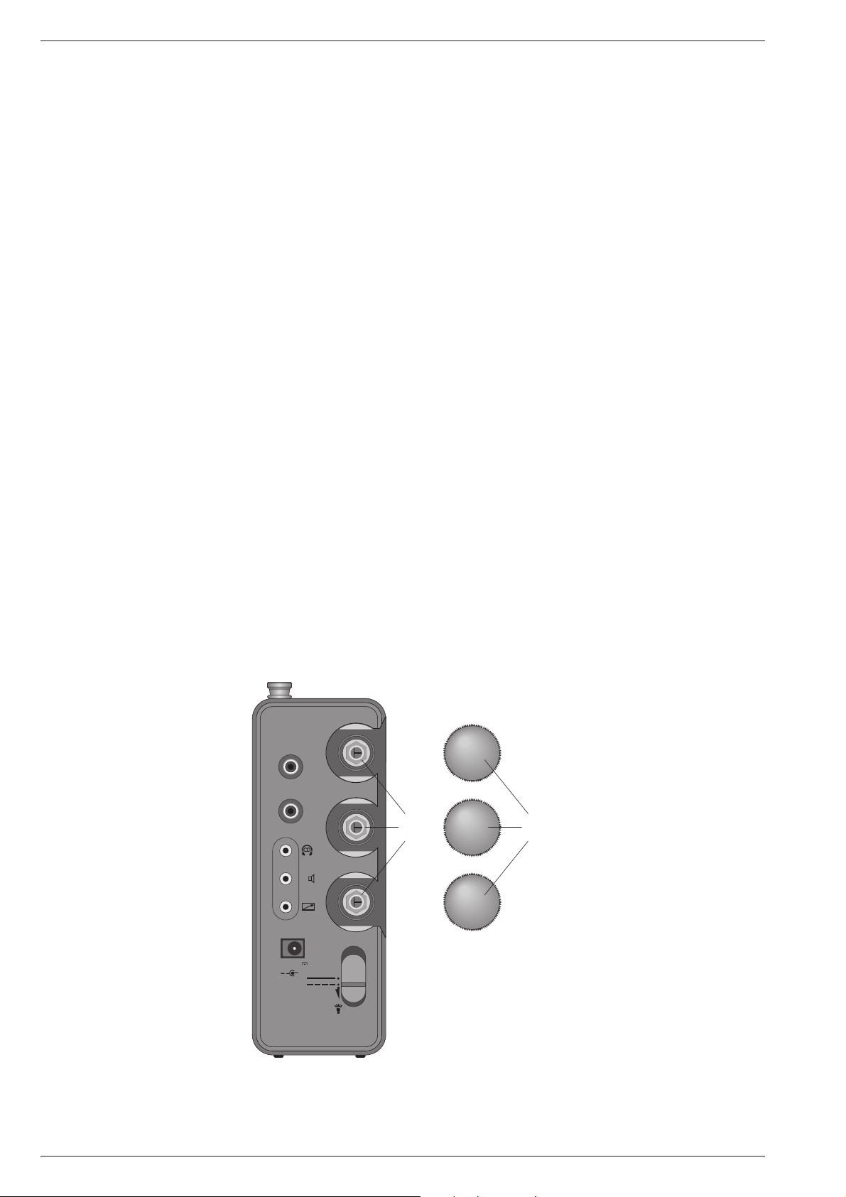
RESET-Taste
Sollte durch äußere Störeinflüsse
(hervorgerufen durch statische
Aufladungen von Teppichböden
oder aufgrund von Gewittern usw.),
die Bedienelektronik des Satellit
700 Fehlinformationen bekom-
men, bzw. die Eingabe völlig blok-
kiert sein, so betätigen Sie die
RESET-Taste in der MEMOFILE-
Box mit einem spitzen Gegen-
stand.
Das Gerät wird dadurch in eine
Grundprogrammierung zurückge-
setzt. Stationsspeicher werden
nicht gelöscht.
Datensicherung
Durch eine auf der Bedienplatte eingebaute, aufladbare Stützbatterie
(Lithiumbatterie, wird automatisch aufgeladen, wenn das Gerät betriebs-
bereit ist) bleiben nach dem Ausschalten alle Speicherinhalte erhalten,
auch wenn das Gerät von seiner Betriebsspannung getrennt wird. Die
Uhr läuft weiter, wird aber nicht angezeigt. Der Erhalt dieser Daten ist
für ca. 1500 Stunden gewährleistet.
Beachten Sie bitte die Sicherheitshinweise für Lithiumbatterien auf
Seite 5.
ACCU
GB
Notes for the Satellit 700
Power Supply
Battery or Accumulator Operation
With 4 "HP2" batteries IEC LR 20 (alkaline-manganese batteries) or Ni
Cd accumulators of same size (commercially available).
- Only use accumulators with the inscription 1,24 V and 4000 mAh.
- Insert the batteries or accumulators with cirrect polarity.
- Attention: For battery operation, the slider switch ACCU/BATT. (in
the battery compartment) must be set to BATT. When batteries are
inserted, never set the switch to ACCU or leave it in this position
(indication ACCU). No responsibility can be accepted for damage
due to wrong operation of charging unit.
- When using Ni Cd accumulators, the switch must be set to ACCU
(Indication ACCU).
Charging Time
With the AC adapter NR90, a charging time of up to 4 days will be
required, depending on the charging state of the accumulators. Because
of a inbuilt charging circuit the accumulators cannot be overloaded
even nor if the AC adapter NR90 is permanently connected.
If the set cannot be switched on, or if the frequency indication only
briefly flashes after switching on, then the supply voltage is too low. If
this should be the case, replace the complete set of batteries or
recharge the accumulators.
- Always remove exhausted batteries immediately!
- If the set is not in use for longer periods, remove batteries even if they
are new!
No responsibility can be accepted for damage due to leaking
batteries.
RESET Button
If, due to external interferences
(caused by static charges of carpets,
thunderstorms, etc.), the control
electronic of the Satellit 700 should
receive wrong information signals, or
if no entries at all are possible, then
press the RESET button in the
MEMOFILE box by a pointed object.
By that the unit is reset to its basic
programming values. The contents
of the individual station memory
positions are not affected.
Data Protection
When the set is switched off, a built-in standby battery (lithium battery,
which is automatically recharged when the unit is ready for operation)
protects all memories, also when no power supply is connected. The
clock continues running, but the time is not displayed. Storage of data
is guaranteed for a duration of 1500 hours. Observe the safety
requirements for lithium batteries on page 5.
BATT
ACCU
234
RESET
RESET
Satellit 700 Hinweise zum Satellit 700 / Notes for the Satellit 700
GRUNDIG Service-Technik
11
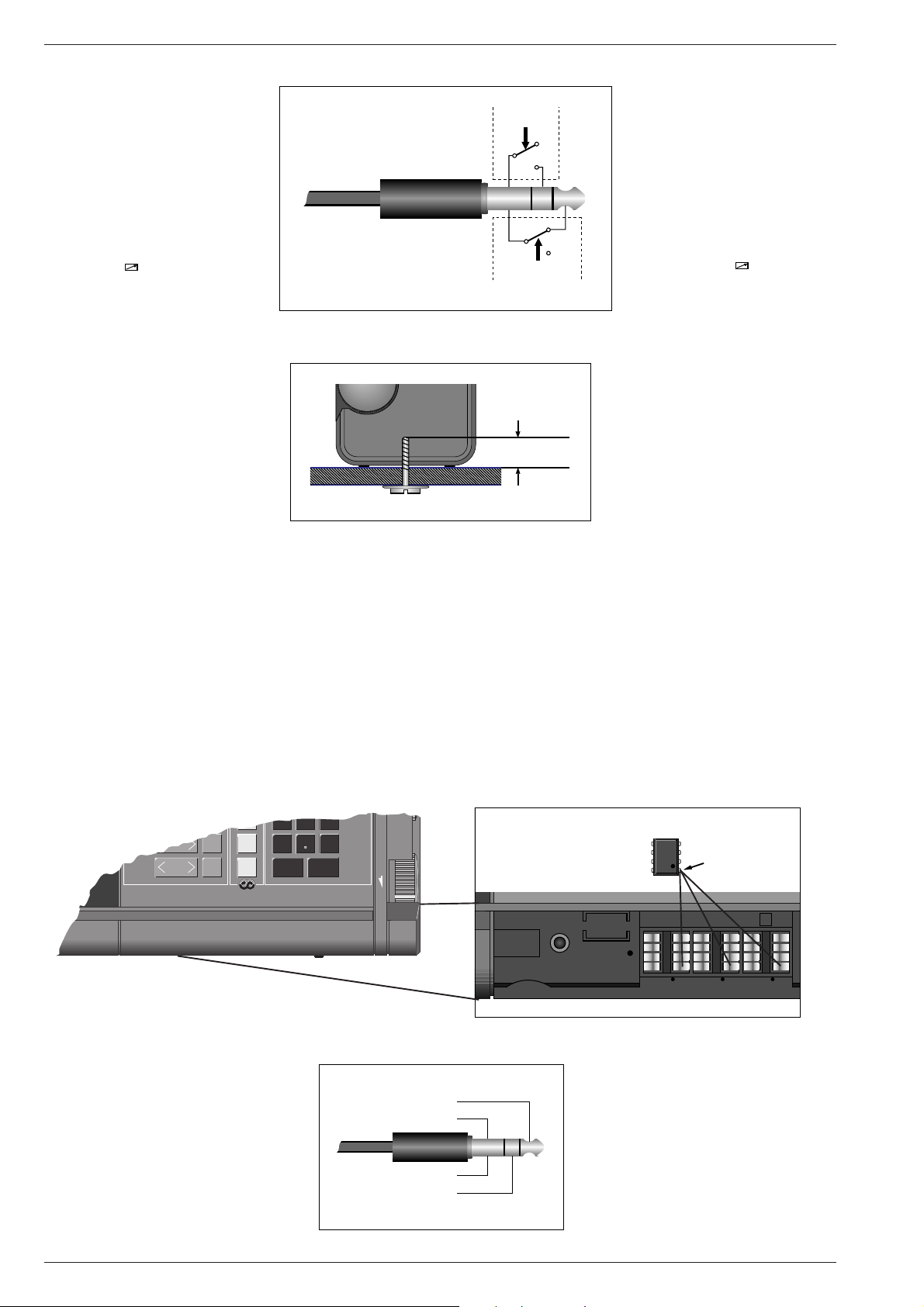
Automatische Steuerung
eines Cassettengerätes
Der Satellit 700 kann ein Cassetten-
gerät mit positiver bzw. negativer
Steuerlogik bei Schaltuhr-Betrieb au-
tomatisch starten bzw. stoppen. Dazu
muß ein entsprechendes Steuerkabel
angefertigt werden. Die Schaltstufe zur
Steuerung des Cassettengerätes ar-
beitet potentialfrei. Die vom Cassetten-
gerät zugeführte Schaltspannung (max.
30V/500mA) wird an der Schaltaus-
gangsbuchse wie folgt beeinflußt:
Befestigen des Gerätes
Der Satellit 700 läßt sich festschrauben.
Hierzu sind im Boden zwei Gewindelöcher
M4.
Verwenden Sie Schrauben, die mindestens
15mm und maximal 19mm länger sind, als
die Materialstärke der Montageebene.
Memofiles
Sie haben die Möglichkeit beim Satellit 700 durch zusätliche
MEMOFILES (ICs) die Speicherkapazität um 3x 512 Speicherplätzezu
erweitern.
Die Einsteckplätze für 3 MEMOFILES befinden sich hinter der Klappe
unterhalb des Bedienfeldes.
Es ist darauf zu achten, daß das MEMOFILE-IC polungsrichtig einge-
setzt wird. Drücken Sie das MEMOFILE vorsichtig in den jeweiligen IC-
Sockel. Beachten Sie auch die Nummerierung der IC-Sockel. Dies ist
für den MEMOFILE-Aufruf wichtig.
Bezeichnung der MEMOFILES: X24C16-P3
Sachnummer: 8305-602-416
Automatic Control of a
Cassette Recorder
With the Satellit 700 it is possible to
automatically start and stop a cassette
recorder which is equipped with a po-
sitive or negativ control logic circuit.
For this, a special connecting lead
must be built. The switching circuit for
controlling the cassette recorder
operates potential-free. The switching
voltage delivered by the cassette
recorder (max. 30V/500mA) is changed
by the switch jack as follows.
Securing the Unit
The Satellit 700 can be secured to an
appropriate surface. For this, two threaded
holes M4 are provided in its base. Only use
screws which are at least 15mm and max.
19mm longer than the thickness of the
material to which the Satellit is to be
secured.
Memofiles
You have the possibility to increase the memory capacity of your
Satellit 700 by 3x512 memory positions with additionally MEMOFILES
(ICs).
The sockets for inserting 3 MEMOFILESare to be found behind the trap
below the keyboard.
Ensure that the MEMOFILE IC be inserted with correct polarity.
Carfully press the MEMOFILE IC into the respective socket. When
doing this, also observe the numbering of the IC sockets. This is of
impertance when later "calling up" the respective MEMOFILE.
Name of the MEMOFILES: X24C16-P3
Order No.:8305-602-416
min
max
15 mm
19 mm
123
Steuerlogik/Control logic:
SAT 700
Schaltstellung bei
eingeschaltetem Satellit :
Switch position with the
Satellit switched on:
SAT 700
Steuerlogik/Control logic:
RESET
234
PIN 1
Loadspeaker Socket
Contact allocation of the plug for two external
loudspeakers.
Lautsprecher-Buchse
Kontaktbelegung des Steckers für zwei Außen-
lautsprecher.
123
Linker Kanal / Left channel
Rechter Kanal / right channel
+
+
-
-
EXCHANGEABLE MEMORY FILES COPY FUNCTION
AGC MGC
RADIO-DATA-SYSTEM
R•D•S
WORLD RECEIVER
789
0
FREE
TIME
I/II
USB
LSB
MENU
A-Z
0-9
MEMORY
FILE
MEMORY
SCAN
SEARCH
SELECT
FREQUENCY
m-BAND
STORE
SYNCH
CL
Hinweise zum Satellit 700 / Notes for the Satellit 700
Satellit 700
12 GRUNDIG Service-Technik
 Loading...