


RRCD-4204
Table of contents
 Loading...
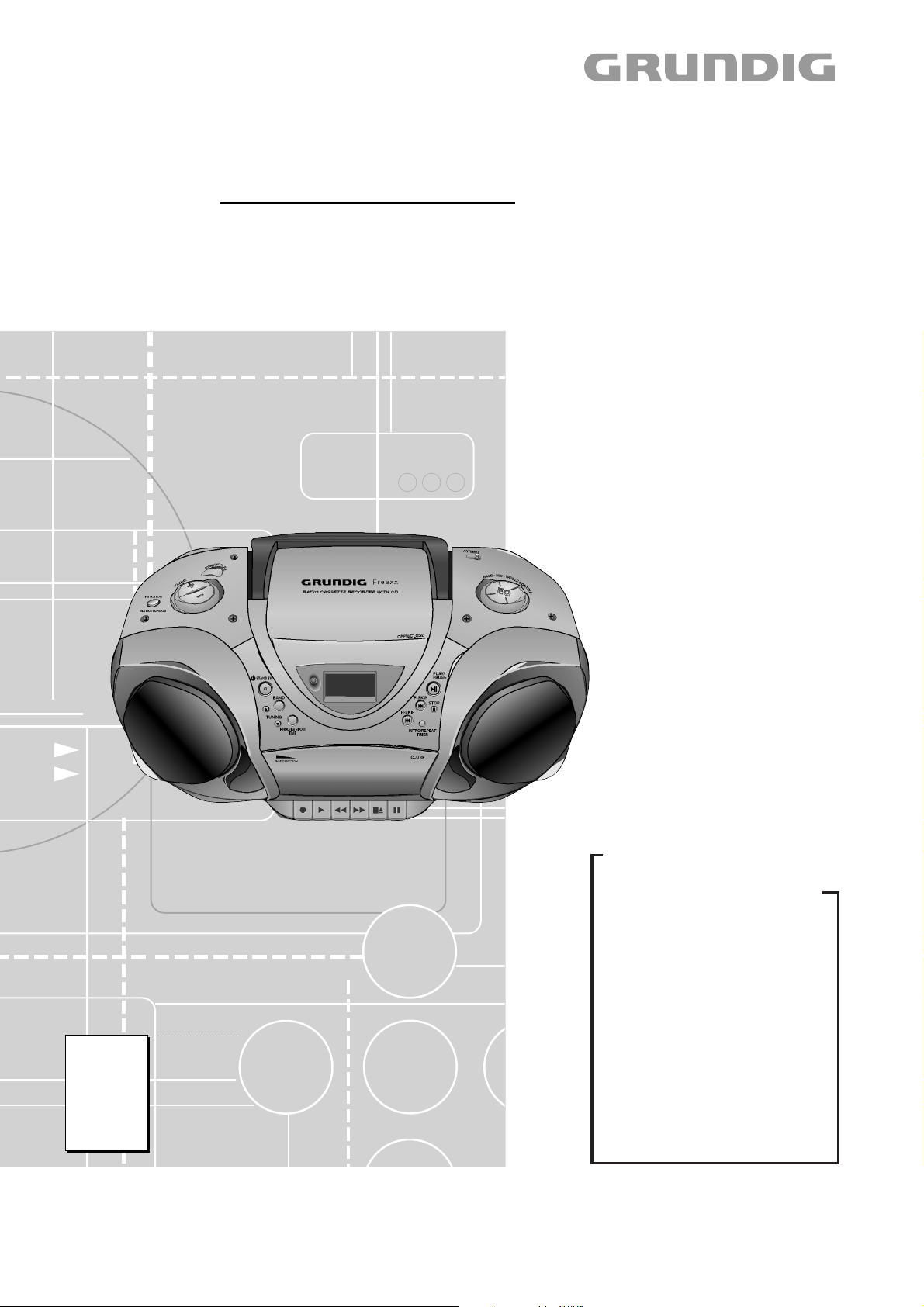
Audio Service Manual
FREAXX 40
RRCD 4204 PLL
GDN5450
Zusätzlich erforderliche Unterlagen für den Komplettservice
Additionally required Service Documents for the Complete Service
Service
Manual
Sicherheit
Safety
Materialnr./Part No.
720108000000
Materialnummer/Part Number 720107725000
Änderungen vorbehalten/Subject to alteration • Printed in Germany FD
H-S44 1002 • 8002/8012, 8003/8013, 8005/8015
http://www.grundig.com
Grundig Service
Hotline Deutschland…
Technik:
TV
TV
SAT
VCR/LiveCam
HiFi/Audio
Car Audio
Telekommunikation
Planatron
Ersatzteil-Verkauf: Mo.-Fr. 8.00-19.00 Uhr
Kundendienst/Werkstätten:
gebührenpflichtig
(8.00-22.00 Uhr)
…Mo.-Fr. 8.00-18.00 Uhr
0180/52318-41
0180/52318-49
0180/52318-48
0180/52318-42
0180/52318-43
0180/52318-44
0180/52318-45
Fax:
Telefon: 0180/52318-40
Telefon:
Fax:
0180/52318-51
0180/52318-99
0180/52318-50Fax:
Mo.-Fr. 8.00-18.00 Uhr
0180/52318-52
0180/52318-46

GRUNDIG Service FREAXX 40 RRCD 4204 PLL
Es gelten die Vorschriften und Sicherheitshinweise gemäß dem Service Manual "Sicherheit",
Materialnummer 720108000000, sowie zusätzlich die eventuell abweichenden, landesspezifischen Vorschriften!
Inhaltsverzeichnis
Seite
Allgemeiner Teil ............................. 1 - 2 … 1 - 8
Messgeräte / Messmittel ............................................................ 1 - 2
Technische Daten ...................................................................... 1 - 3
Servicehinweise ......................................................................... 1 - 3
Ausbauhinweise ......................................................................... 1 - 4
Bedienhinweise .......................................................................... 1 - 7
Abgleichvorschriften ..................... 2 - 1 … 2 - 2
Schaltpläne und
Platinenabbildungen .................... 3 - 1 … 3 - 14
Blockschaltplan .......................................................................... 3 - 1
Verdrahtungsplan ....................................................................... 3 - 2
Schaltpläne:
Tuner ...................................................................................... 3 - 4
CD-Servo-Platte ..................................................................... 3 - 6
Haupt-Platte ......................................................................... 3 - 10
Gleichrichter-Platte ............................................................... 3 - 10
Kopfhörer-Platte ................................................................... 3 - 10
Display-Platte ....................................................................... 3 - 12
MCU-Platte ........................................................................... 3 - 12
Tasten-Platten ...................................................................... 3 - 12
Platinenabbildungen:
Tuner-Platte ........................................................................... 3 - 3
FM-Mode-Platte ..................................................................... 3 - 3
CD-Servo-Platte ..................................................................... 3 - 8
Haupt-Platte ........................................................................... 3 - 9
Gleichrichter-Platte ................................................................. 3 - 9
Kopfhörer-Platte ..................................................................... 3 - 9
Tasten-Platten ...................................................................... 3 - 13
Display-Platte ....................................................................... 3 - 14
MCU-Platte ........................................................................... 3 - 14
The regulations and safety instructions shall be
valid as provided by the "Safety" Service Manual,
part number 720108000000, as well as the respective national deviations!
Table of Contents
Page
General Section ............................ 1 - 2 … 1 - 10
Measuring Instruments / Equipment .......................................... 1 - 2
Technical Data ........................................................................... 1 - 3
Service Hints .............................................................................. 1 - 3
Disassembly Instructions ........................................................... 1 - 4
Operating Hints .......................................................................... 1 - 9
Adjustment Procedures................. 2 - 3 … 2 - 4
Circuit Diagrams and
Layout of the PCBs ...................... 3 - 1 … 3 - 14
Block Diagram ............................................................................ 3 - 1
Wiring Diagram .......................................................................... 3 - 2
Circuit Diagrams:
Tuner ...................................................................................... 3 - 4
CD Servo PCB ....................................................................... 3 - 6
Main PCB ............................................................................. 3 - 10
Rectifier PCB ........................................................................ 3 - 10
Headphone PCB .................................................................. 3 - 10
Display PCB ......................................................................... 3 - 12
MCU PCB ............................................................................. 3 - 12
Key PCBs ............................................................................. 3 - 12
Layout of the PCBs:
Tuner PCB ............................................................................. 3 - 3
FM Mode PCB ........................................................................ 3 - 3
CD Servo PCB ....................................................................... 3 - 8
Main PCB ............................................................................... 3 - 9
Rectifier PCB .......................................................................... 3 - 9
Headphone PCB .................................................................... 3 - 9
Key PCBs ............................................................................. 3 - 13
Display PCB ......................................................................... 3 - 14
MCU PCB ............................................................................. 3 - 14
Explosionszeichnung und
Ersatzteilliste .................................. 4 - 1 … 4 - 4
Allgemeiner Teil
Messgeräte / Messmittel
Mess- / Wobbel-Sender
Klirrfaktor-Messgerät
Oszilloskop
Digital-Voltmeter
Tonhöhenschwankungsmesser
NF-Voltmeter
Frequenzzähler
FE-Testcassette (z.B. 449)
Exploded View and
Spare Parts List .............................. 4 - 1 … 4 - 4
General Section
Measuring Instruments / Equipment
Signal / Sweep Generator
Distortion Meter
Oscilloscope
Digital Voltmeter
Wow and Flutter Meter
AF Voltmeter
Frequency Counter
FE Test Cassette (e.g. 449)
1 - 2
GRUNDIG Service FREAXX 40 RRCD 4204 PLL
Technische Daten
Spannungsversorgung
Netzbetrieb: ................................................................ 230V, 50/60Hz
Max. Leistungsaufnahme: ..................................... ca. 40W (Betrieb)
................................................................................. < 2W (Standby)
Batteriebetrieb: ............................... 6 x 1,5V (IEC/LR20/AM1/D-size)
Backup-Batterien: ........................................ 2 x 1,5V (AM3/LR6/AA)
Verstärkerteil
DIN 45324, 10% THD
Musikleistung: ........................................................................ 2 x 5W
Sinusleistung: ......................................................................... 2 x 3W
Stereo-Kopfhörer-Klinkenbuchse ........................................ 3,5mm ø
Rundfunkteil
Wellenbereiche
FM .......................................................................... 87,5 ...108,0MHz
MW ........................................................................... 522 ... 1620kHz
LW .............................................................................. 144 ... 281kHz
CD Teil
Frequenzgang: ...........................................................20Hz ... 20kHz
Geräuschspannungsabstand: ................................................. ≥65dB
Cassettenteil
Tonträger: ................................. Compact-Cassette nach DIN 45516
Spurlage:...................................................... Viertelspur international
Bandgeschwindigkeit: .................................................... 4,76cm/sec.
Motor: ................................................................................. DC Motor
Frequenzbereich: ..................................................... 125Hz ... 10kHz
Geräuschspannungsabstand: ................................................. ≥42dB
Gleichlaufschwankungen: ..................................................... ≤0,35%
Abmessungen und Gewicht
B x H x T ......................................................... 444 x 184,5 x 253mm
Gewicht ...................................................................................3,95kg
Technical Data
Power supply
Mains operation: ........................................................ 230V, 50/60Hz
Max. power consumption: .......................... Approx. 40W (operation)
.................................................................................. < 2W (standby)
Battery operation:........................... 6 x 1.5V (IEC/LR20/AM1/D size)
Backup Batteries: ......................................... 2 x 1.5V (AM3/LR6/AA)
Amplifier part
DIN 45324, 10% THD
Music signal power: ............................................................... 2 x 5W
Sine wave power: ................................................................... 2 x 3W
Stereo headphone jack ....................................................... 3.5mm ø
Radio
Frequency bands
FM ......................................................................... 87.5 ... 108.0MHz
MW ........................................................................... 522 ... 1620kHz
LW .............................................................................. 144 ... 281kHz
CD unit
Frequency response: ................................................. 20Hz ... 20kHz
Noise voltage ratio: ................................................................. ≥65dB
Cassette unit
Sound recording medium: ......Compact cassette according to DIN 45516
Track position: .......................................... International quarter-track
Tape speed: ................................................................... 4.76cm/sec.
Motor: ................................................................................. DC motor
Frequency range: .....................................................125Hz ... 10kHz
Noise voltage ratio: ................................................................. ≥42dB
Band speed fluctuation: ........................................................ ≤0.35%
Dimensions and weight
W x H x D ........................................................444 x 184.5 x 253mm
Weight .....................................................................................3.95kg
Servicehinweise
Achtung: ESD-Vorschriften beachten
Vor Öffnen des Gehäuses Netzstecker ziehen.
Leitungsverlegung
Bevor Sie die Leitungen und insbesondere die Masseleitungen lösen,
muss die Leitungsverlegung zu den einzelnen Baugruppen beachtet
werden.
Nach erfolgter Reparatur ist es notwendig, die Leitungsführung wieder
in den werkseitigen Zustand zu versetzen um evtl. spätere Ausfälle
oder Störungen zu vermeiden.
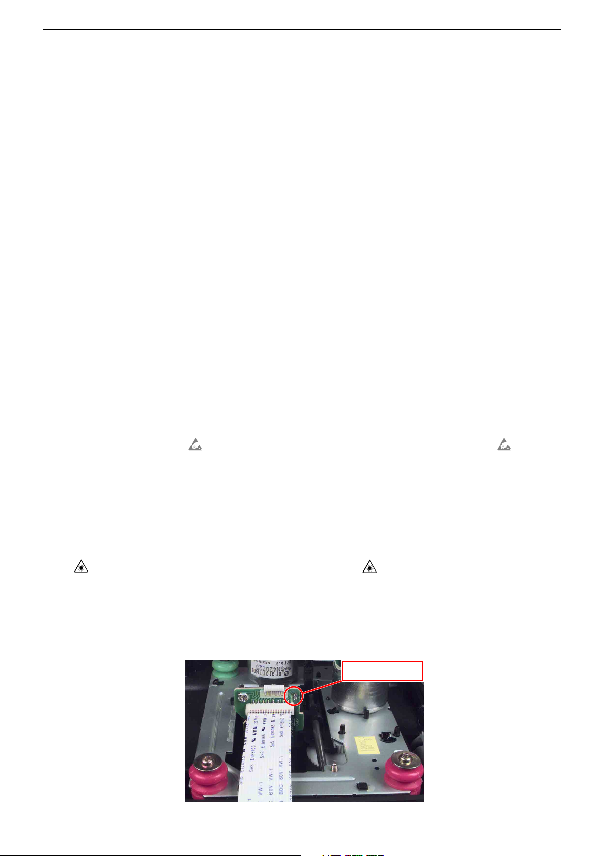
CD-Teil
Bei Ausbau der CD-Lasereinheit muss vor Abziehen der Steckverbindungen eine Schutzlötstelle auf der Leiterplatte der
Lasereinheit angebracht werden, um eine Zerstörung der Laserdiode durch statische Aufladung zu vermeiden.
Beim Einbau einer neuen Lasereinheit (CD-Laufwerk) muss
nach Einstecken der Steckverbinder die werkseitig angebrachte
Schutzlötstelle entfernt werden!
ESD
Service Hints
Attention: Observe the ESD safety regulations
Disconnect the mains plug before opening the set.
Wiring
Before disconnecting any leads and especially the earth connecting
leads observe the way they are routed to the individual assemblies.
On completion of the repairs the leads must be laid out as originally
fitted at the factory to avoid later failures or disturbances.
CD Section
When removing the Laser pick-up, the Laser pick-up PCB must be
provided with a protective soldered joint before unplugging the
connectors to avoid damage to the Laser diode by static charges.
When inserting the new Laser pick-up (CD drive mechanism) the
soldered joint fitted at the factory must be removed after the
connectors are plugged in.
Schutzlötstelle
protective soldered joint
ESD
1 - 3
GRUNDIG Service FREAXX 40 RRCD 4204 PLL
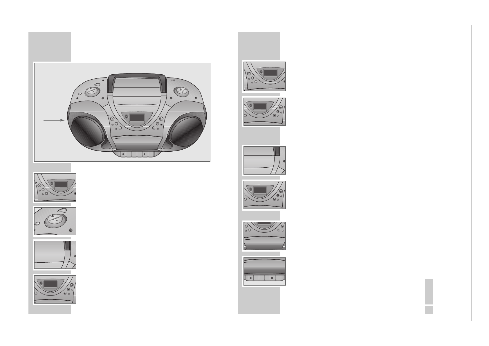
Ausbauhinweise
Bevor Sie Leitungen lösen, muss die Leitungsverlegung beachtet
werden. Nach erfolgter Reparatur ist es notwendig, die Leitungsführung in den werkseitigen Zustand zu versetzen.
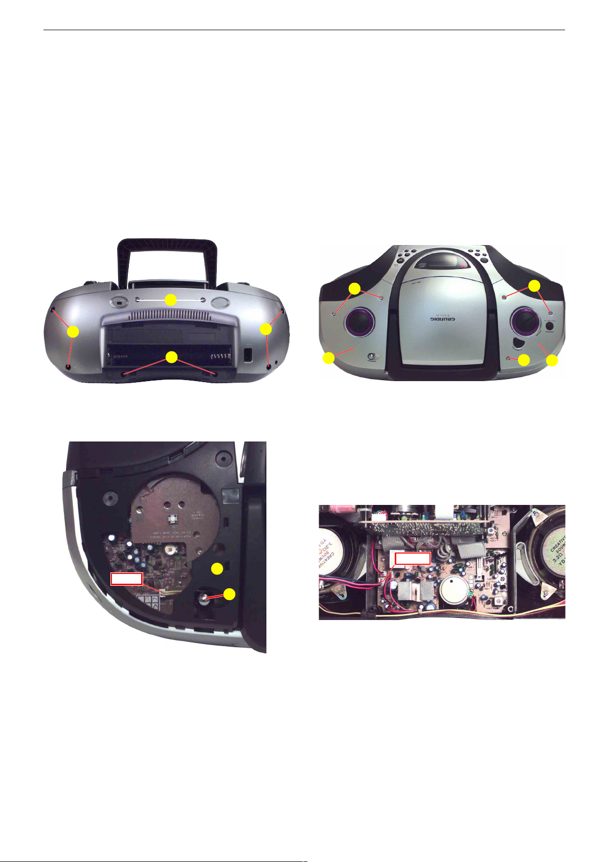
1. Gehäuserückteil
- 2 Schrauben A, 4 Schrauben B und 2 Schrauben C herausschrauben (Fig. 1).
- 2 Inbusschrauben D (Fig. 2) herausschrauben.
- Blende ɟ| ausrasten und abnehmen (Fig. 2).
- Steckverbindung CN551 (Fig. 3) abziehen.
- Gehäuserückteil so nach hinten wegnehmen, dass die Antenne aus
dem Gehäuserahmen įɠ (Fig. 3) ausgefädelt werden kann.
- Steckverbindung CN1201 abziehen (Fig. 4).
A
B
B
Disassembly Instructions
Before disconnecting any leads observe the way they are routed.
On completion of the repairs the leads must be laid out as
originally fitted at the factory.
1. Cabinet Rear Part
- Undo 2 srews A, 4 screws B and 2 screws C (Fig. 1).
- Undo 2 hex socket head screws D (Fig. 2).
- Disengage and remove mask ɟ| (Fig. 2).
- Disconnect plug-in connector CN551 (Fig. 3).
- Remove the cabinet rear part to the rear side to slip out the aerial
from the cabinet frame įɠ (Fig. 3) .
- Disconnect plug-in connector CN1201 (Fig. 4).
D
F
Fig. 1
Fig. 3
CN511
C
įɠ
E
ɟ|
Fig. 2
Fig. 4
CN1201
F
įɚ
2. Gehäuseoberteil
- Gehäuserückteil abnehmen (Punkt 1).
- 3 Inbusschrauben F (Fig. 2) herausschrauben.
- Blende įɚ (Fig. 2) ausrasten und abnehmen.
- 2 Schrauben H (Fig. 5) herausschrauben.
- 4 Rastungen I (Fig. 6) ausrasten.
- Gehäuseoberteil hinten vorsichtig nach unten drücken, damit die
Rastungen J (Fig. 7) ausgerastet werden.
- Steckverbindungen bei Bedarf lösen.
2. Cabinet Top Part
- Remove the cabinet rear part (point 1).
- Undo 3 hex socket head screws F (Fig. 2).
- Disengage and remove mask įɚ (Fig. 2).
- Undo 2 screws H (Fig. 5).
- Disengage 4 catches I (Fig. 6).
- Push the cabinet top part carefully downside at the rear to disengage
the catches J (Fig. 7).
- Disengage plug-in connections if necessary.
1 - 4

GRUNDIG Service FREAXX 40 RRCD 4204 PLL
H
Fig. 5
J
Fig. 7
3. Netzteilplatte
- Gehäuserückteil abnehmen (Punkt 1).
- 4 Schrauben K (Fig. 8) herausschrauben.
- Blende ɟr (Fig. 8) abnehmen.
- 3 Schrauben L (Fig. 8) herausschrauben.
- Steckverbindungen bei Bedarf lösen.
4. Tuner-Platte
- Gehäuserückteil abnehmen (Punkt 1).
- 4 Schrauben M (Fig. 9) herausschrauben.
- Steckverbindungen bei Bedarf lösen.
5. Tasten-Platte
- Gehäuserückteil abnehmen (Punkt 1).
- 5 Schrauben N (Fig. 9) herausschrauben.
- Steckverbindungen bei Bedarf lösen.
I
Fig. 6
K
K
L
Fig. 8
3. Rectifier PCB
- Remove the cabinet rear part (point 1).
- Undo 4 screws K (Fig. 8).
- Remove mask ɟr (Fig. 8).
- Undo 3 screws L (Fig. 8).
- Disengage plug-in connections if necessary.
4. Tuner PCB
- Remove the cabinet rear part (point 1).
- Undo 4 screws M (Fig. 9).
- Disengage plug-in connections if necessary.
5. Key PCB
- Remove the cabinet rear part (point 1).
- Undo 5 screws N (Fig. 9).
- Disengage plug-in connections if necessary.
I
ɟr
Fig. 9
N
M
O
1 - 5
GRUNDIG Service FREAXX 40 RRCD 4204 PLL
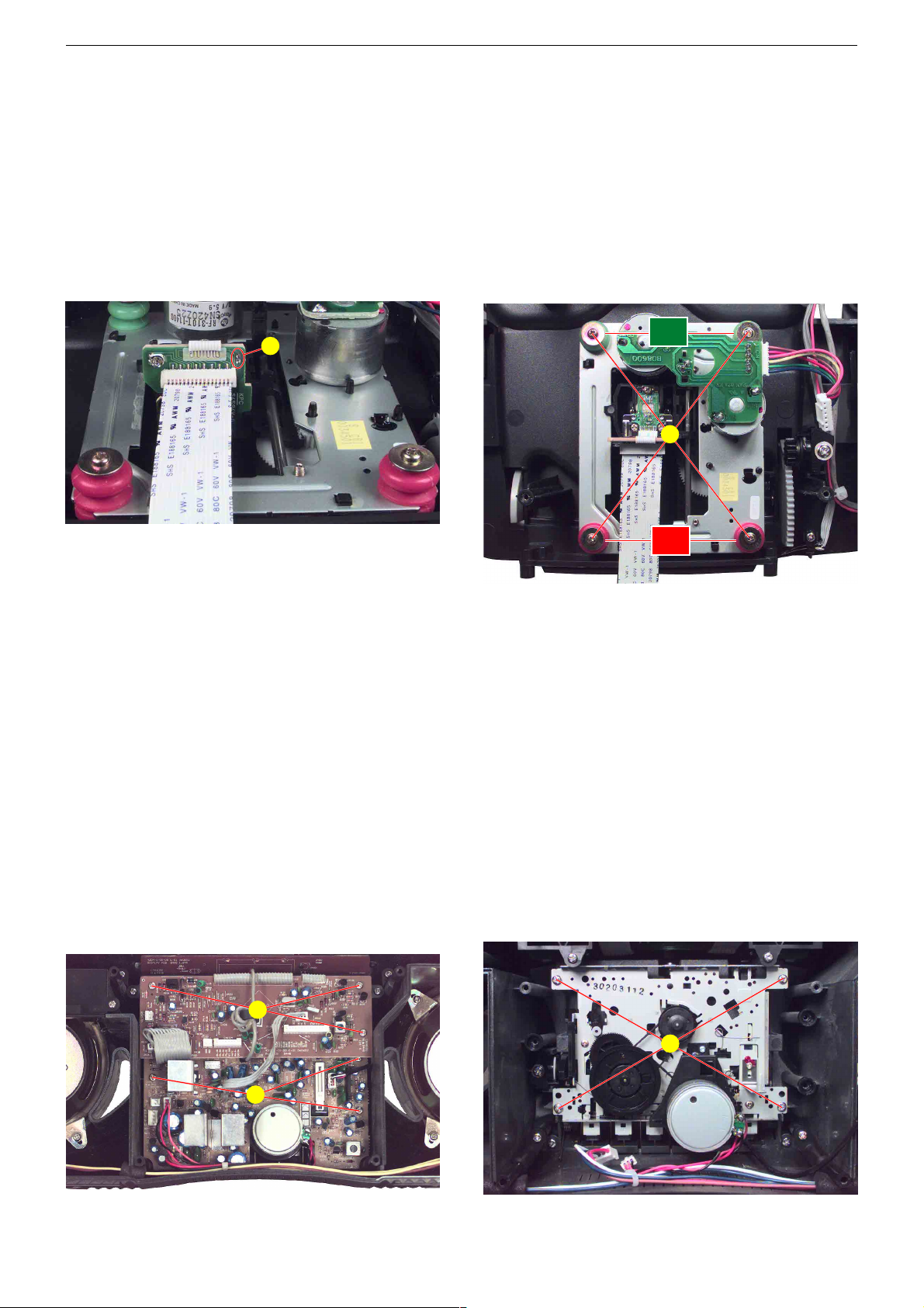
6. CD-Platte
- Gehäuserückteil abnehmen (Punkt 1).
- 4 Schrauben O (Fig. 9) herausschrauben.
- Vor Abziehen des Flexprints zum CD-Laufwerk muss die Schutzlötstelle
schlossen werden.
- Steckverbindungen bei Bedarf lösen.
7. Pickup
- CD-Platte ausbauen (Punkt 6).
- 4 Schrauben
Beim Einbau die Farbe der Puffer beachten!
P (Fig. 10) auf der Leiterplatte der Lasereinheit kurzge-
Q (Fig. 11) herausschrauben.
P
6. CD PCB
- Remove the cabinet rear part (point 1).
- Undo 4 screws O (Fig. 9).
- Shortcircuit the protective soldered joint P (Fig. 10) at the Laser
pick-up PCB before disconnecting the flexprint to the CD mechanism.
- Disengage plug-in connections if necessary.
7. Pickup
- Remove the CD PCB (point 6).
- Undo 4 screws Q (Fig. 11).
When reassembling pay attention to the different colours of the
cushions!
grün
green
Q
Fig. 10 Fig. 11
8. MCU-Leiterplatte
- Gehäuserückteil abnehmen (Punkt 1).
- Gehäuseoberteil abnehmen (Punkt 2).
- 3 Schrauben R (Fig. 12) herausschrauben.
- Steckverbindungen bei Bedarf lösen.
9. Haupt-Leiterplatte
- MCU-Leiterplatte ausbauen (Punkt 8).
- 3 Schrauben S (Fig. 12) herausschrauben.
- Steckverbindungen bei Bedarf lösen.
10. Cassetten-Laufwerk
- Haupt-Leiterplatte ausbauen (Punkt 9).
- 4 Schrauben T (Fig. 13) herausschrauben.
- Cassettenfach öffen.
8. MCU PCB
- Remove the cabinet rear part (point 1).
- Remove the cabinet top part (point 2).
- Undo 3 screws R (Fig. 12).
- Disengage plug-in connections if necessary.
9. Main PCB
- Remove the MCU PCB (point 8).
- Undo 4 screws S (Fig. 12).
- Disengage plug-in connections if necessary.
10. Cassette Mechanism
- Remove the Main PCB (point 9).
- Undo 4 screws T (Fig. 13).
- Open the cassette compartment.
rot
red
R
S
Fig. 12 Fig. 13
1 - 6
T

Bedienhinweise
4
G
R-R-
K
R-R-
R
O
U
N
D
/
U
Bedienelemente
Allgemein
Ǽ
STANDBY Schaltet das Gerät in Bereitschaft (Stand-by) und
aus Bereitschaft wieder ein.
RADIO/TAPE/CD Schaltet zwischen den Programmquellen RADIO,
TAPE und CD um.
SURROUND/U.B.S. Schaltet Raumklang ein und aus; länger drücken:
schaltet das Ultra Bass System ein und aus.
EQ Zum Einstellen des Equalizers (BASS, MID oder
TREBLE).
VOLUME +
–
Ändern die Lautstärke.
PROG/RANDOM Zum Einstellen des 12- oder 24-Stunden-Formats,
TIME zum Einstellen der Uhrzeit.
INTRO/REPEAT Zum Einstellen des Einschalt-Timers.
TIMER
PHONES Kopfhörerbuchse, zum Anschließen eines Stereo-
Kopfhörers mit Klinkenstecker (ø 3,5 mm), linke
Geräteseite;
die Lautsprecher des Gerätes werden automatisch
abgeschaltet.
AC~ Buchse zum Anschließen des Netzkabels, Gerä-
terückseite.
AUF EINEN BLICK
_______________________________
E
Q
R-R-
PHONES
DEUTSCH
5
Radio-Teil
ANTENNA Teleskopantenne für den FM (UKW)-Empfang.
BAND Wellenbereichesumschalter FM (UKW), MW (Mit-
telwelle) und LW (Langwelle).
TUNING
Ń
Ľ
Längeres Drücken startet den Frequenzsuchlauf;
kurzes Drücken schaltet die Frequenz schrittweise
weiter.
PROG/RANDOM Startet und unterbricht den automatischen Pro-
TIME grammsuchlauf;
zum Speichern von Rundfunk-Programmen.
F-SKIP
9
Zum Anwählen gespeicherter Rundfunk-Pro-
R-SKIP
8
gramme (Presets).
FM MODE Zum Umschalten auf Mono bei schlechtem Stereo-
Empfang, Geräterückseite.
CD-Teil
OPEN/CLOSE Zum Öffnen und Schließen des CD-Faches.
PLAY/PAUSE
ı
II Startet die Wiedergabe einer CD; schaltet auf Wie-
dergabe-Pause.
F-SKIP
9
Kurzes Drücken: wählt einen Titel an;
R-SKIP
8
längeres Drücken: sucht eine bestimmte Passage.
PROG/RANDOM Zum Speichern eines CD-Musikprogrammes;
TIME zum Abspielen von CD-Titeln in zufälliger Reihen-
folge.
INTRO/REPEAT Zum Anspielen der CD-Titel;
TIMER zum Wiederholen eines Titels oder der ganzen
CD.
STOP
7
Beendet die Wiedergabe der CD;
löscht das Musikprogramm der CD.
Cassetten-Teil
CLOSE Cassetten-Fach, zum Schließen hier drücken.
}
Zeigt die Laufrichtung der Cassette an.
TAPE DIRECTION
●
Startet die Aufnahme.
ı
Startet die Wiedergabe.
ıı
Spult die Cassette zum Bandende.
ľľ
Spult die Cassette zum Bandanfang.
■/
ə
Beendet die Wiedergabe/Aufnahme;
öffnet das Cassettenfach.
II Pause bei Aufnahme und Wiedergabe.
AUF EINEN BLICK
____________________________________
G
R-R-
G
R-R-
K
R-R-
T
A
S
Bedienungsanleitung, deren Materialnummer Sie in der entsprechenden Ersatzteilliste finden.
Dieses Kapitel enthält Auszüge aus der Bedienungsanleitung. Weitergehende Informationen entnehmen Sie bitte der gerätespezifischen
GRUNDIG Service FREAXX 40 RRCD 4204 PLL
rea xx
83344
8
F
E
S
O
L
C
/
N
E
P
O
PLAY/
PAUSE
F-SKIP
STOP
R-SKIP
INTRO/REPEAT
TIMER
C
L
O
S
E
!
!
ə
ə
ǵ
RADIO CASSETTE RECORDER WITH CD
TIME
STANDBY
AN
T
E
N
N
A
M
-
I
D
S
S
-
T
A
R
B
E
B
L
E
C
O
N
T
R
O
L
BAND
TUNING
PROG/RANDOM
TIME
/RANDOM
TIME
F
SETTE RECORDER WITH CD
reaxx
E
P
O
R-S
PLAY/
PAUSE
F-SKIP
STOP
R-SKIP
INTRO/REPEAT
TIMER
E
S
O
L
C
/
N
1 - 7
FUNCTION
RADIO/T
APE/CD
N
U
O
R
R
U
S
E
M
U
L
O
V
D
/
U
.
B
.
S
STANDBY
BAND
TUNING
PROG/RANDOM
TAPE DIRECTION
STANDBY
BAND
TUNING
PROG/RANDOM
U
N
CTIO
N
APE/C
/T
D
IO
R-S
TIME
.
B
R
.
U
S
S
E
M
U
L
O
V
SETTE RECORDER WITH CD
/RANDOM
TIME
E
S
O
L
C
/
N
E
P
O
PLAY/
PAUSE
F-SKIP
STOP
R-SKIP
INTRO/REPEAT
TIMER
reaxx
F
PLAY/
PAUSE
F-SKIP
STOP
TIME
NING
E DIRECTION
/RANDOM
BAND
TAPE DIRECTION
PROG/RANDOM
TIME
83344
8
R-SKIP
ə
ə
INTRO/REPEAT
TIMER
R-SKIP
!
!
F-SKIP
INTRO/REPE
C
L
S
TIMER
O
S
E
C
L
O
6
Die Anzeigen
Das Ultra Bass System ist aktiviert.
SURROUND Der Raumklang ist aktiviert.
BASS/MID/ Zeigt die Einstellung des Equalizers an.
TREBLE
00
00:000Im Radio-Betrieb: zeigt den Programmplatz und die
Frequenz an.
CH Programmplatzanzeige.
FM/MW/LW Zeigt den Wellenbereich an.
MHz/kHz Frequenzanzeige.
ɳ
Zeigt Stereo-Empfang an.
00
00:00 Im CD-Betrieb: zeigt die Gesamtzahl der Titel, den
aktuellen Titel, die Gesamtspielzeit oder die abgelaufene Spielzeit an.
TR Titelanzeige.
ı
Zeigt die Wiedergabe einer CD an.
ı
II Zeigt Wiedergabe-Pause an.
REPEAT 1 Der aktuelle Titel wird wiederholt abgespielt.
REPEAT ALL Alle CD-Titel werden wiederholt abgespielt.
RANDOM Die Titel werden in zufälliger Reihenfolge abgespielt.
PROGRAM Ein Musikprogramm wird gespeichert oder abge-
spielt.
w Der Einschalt-Timer ist aktiviert.
U.B.S.
AUF EINEN BLICK
____________________________________
00:00
00
REPEAT 1 ALL
RANDOM
SURROUND
INTRO
R
II
CH
TR
LW
MW
FM
ɳ
MHz
kHz
U.B.S.
BASSMIDTREBLE
PROGRAM
w
DEUTSCH
7
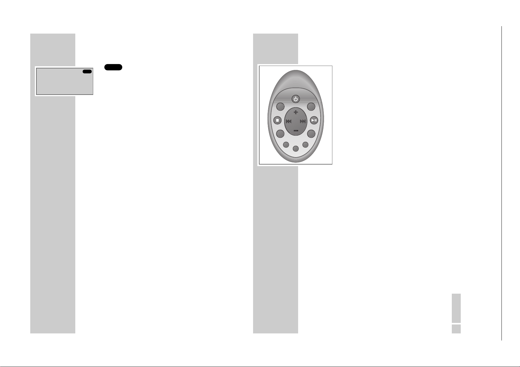
Die Fernbedienung
Ǽ
STANDBY Schaltet das Gerät in Bereitschaft (Stand-
by) und aus Bereitschaft wieder ein.
SOURCE Wählt die Programmquelle RADIO, CD
oder TAPE.
BAND Im Tuner-Betrieb: schaltet zwischen den
Wellenbereichen FM, MW und LW um.
PLAY/PAUSE Im CD-Betrieb: startet die Wiedergabe
ı
II einer CD; schaltet auf Wiedergabepause.
RANDOM Im CD-Betrieb: zum Speichern eines CD-
PROGRAM Musikprogrammes, zum Abspielen von CD-
TIME Titeln in zufälliger Reihenfolge.
Zum Einstellen der Uhrzeit.
EQUALIZER Zum Einstellen des Equalizers (BASS, MID
oder TREBLE).
SURROUND Schaltet den Raumklang ein und aus.
SOUND
UBS Schaltet das Ultra Bass System ein und aus.
INTRO/REPEAT Im CD-Betrieb: zum Anspielen der CD-Titel, zum
TIMER Wiederholen eines Titels oder der ganzen CD.
Zum Einstellen des Einschalt-Timers.
STOP
7
Im CD-Betrieb: beendet die Wiedergabe der CD;
löscht das Musikprogramm der CD.
5a s 6 Im Tuner-Betrieb: wählen gespeicherte
Rundfunkprogramme. Im CD-Betrieb: kurzes
Drücken wählt einen Titel an; längeres Drücken
sucht eine bestimmte Passage.
+
–
Ändern die Lautstärke.
AUF EINEN BLICK
____________________________________
GRUNDIG Service FREAXX 40 RRCD 4204 PLL
1 - 8
SOURCE
STOP
INTRO/
REPEAT/TIMER
ǵ
STANDBY
PROGRAM/TIME
UBS EQUALIZER
SURROUND
SOUND
BAND
PLAY/
PAUSE
RANDOM/
1 - 9
24
G
R-R-
K
R-R-
R
O
U
N
D
/
U
Controls
General
Ǽ
STANDBY Switches the device to and from standby mode.
RADIO/TAPE/CD Function switch for selecting RADIO, TAPE or CD
mode.
SURROUND/U.B.S. Switches surround sound on and off. Hold down
to switch the Ultra Bass System on and off.
EQ For adjusting the equalisers (BASS, MID and TREBLE).
VOLUME +
–
Adjusts the volume.
PROG/RANDOM For setting the 12-hour or 24-hour format.
TIME For setting the time.
INTRO/REPEAT For setting the switch-on timer.
TIMER
PHONES Headphone jack for connecting a headphone set
with a jack plug (ø 3.5 mm) on the left side of the
device.
This automatically switches off the loudspeakers.
AC~ Socket for connecting the power cord (on the back
of the device).
OVERVIEW
___________________________________________
E
Q
R-R-
PHONES
ENGLISH
25
Radio unit
ANTENNA Telescopic antenna for FM (VHF) reception.
BAND Frequency band switch FM (VHF), MW (medium
wave) and LW (long wave).
TUNING
Ń
Ľ
Hold down to start the station search. Press briefly
to change the frequency in small steps.
PROG/RANDOM Starts and interrupts the automatic
TIME station search.
For storing radio stations.
F-SKIP
9
To select stored radio
R-SKIP
8
stations (presets).
FM MODE For switching to mono reception in case of poor
stereo reception (on the back of the device).
CD unit
OPEN/CLOSE Opens and closes the CD compartment.
PLAY/PAUSE
ı
II Starts and pauses CD playback.
F-SKIP
9
Press briefly to select a track.
R-SKIP
8
Hold down to look for a particular passage.
PROG/RANDOM For storing a CD track memory.
TIME For playing CD tracks in random order.
INTRO/REPEAT Plays the start of a CD track.
TIMER Repeats a track or the whole CD.
STOP
7
Ends CD playback.
Deletes the track memory for the CD.
Tape unit
CLOSE Press here to close the cassette compartment.
}
Indicates the tape direction.
TAPE DIRECTION
●
Starts recording.
ı
Starts playback.
ıı
Fast forwards the tape to the end.
ľľ
Rewinds the tape to the beginning.
■/
ə
Ends playback/recording.
Opens the tape compartment.
II Pauses recording and playback.
OVERVIEW
____________________________________________
G
R-R-
G
R-R-
K
R-R-
T
A
S
U
IO
SETTE RECORDER WITH CD
/RANDOM
TIME
Operating Hints
of which is indicated in the relevant spare parts list.
This chapter contains excerpts from the operating instructions. For further particulars please refer to the appropriate user instructions the part number
FUNCTION
RADIO/TAPE/CD
STANDBY
BAND
TUNING
PROG/RANDOM
N
CTIO
N
APE/C
/T
D
R-S
TIME
.
B
R
.
U
S
S
E
M
U
L
O
V
reaxx
F
E
S
O
L
C
/
N
E
P
O
PLAY/
PAUSE
F-SKIP
STOP
R-SKIP
INTRO/REPEAT
TIMER
D
/
N
U
U
O
.
B
R
R
.
U
S
S
E
M
U
L
O
V
ǵ
RADIO CASSETTE RECORDER WITH CD
STANDBY
BAND
TUNING
PROG/RANDOM
TIME
TAPE DIRECTION
83344
8
reaxx
F
E
S
O
L
C
/
N
E
P
O
PLAY/
PAUSE
F-SKIP
STOP
R-SKIP
INTRO/REPEAT
TIMER
C
L
O
S
E
!
!
ə
ə
STANDBY
AN
T
E
N
N
A
M
-
I
D
S
S
-
T
A
R
B
E
B
L
E
C
O
N
T
R
O
L
BAND
TUNING
PROG/RANDOM
TIME
/RANDOM
TIME
F
SETTE RECORDER WITH CD
/RANDOM
TIME
BAND
NING
PROG/RANDOM
TIME
TAPE DIRECTION
E DIRECTION
83344
8
reaxx
R-S
PLAY/
PAUSE
F-SKIP
STOP
R-SKIP
INTRO/REPEAT
TIMER
E
S
O
L
C
/
N
E
P
O
PLAY/
PAUSE
F-SKIP
STOP
R-SKIP
INTRO/REPEAT
TIMER
F-SKIP
S
R-SKIP
INTRO/REPE
TIMER
C
L
O
S
E
C
L
O
!
!
ə
ə
GRUNDIG Service FREAXX 40 RRCD 4204 PLL

26
The display
The Ultra Bass System is activated.
SURROUND Surround sound is activated.
BASS/MID/ Displays the equaliser setting.
TREBLE
00
00:000In radio mode: displays the station position and the
frequency.
CH Station position display.
FM/MW/LW Displays the waveband.
MHz/kHz Frequency display.
ɳ
Displays stereo reception.
00
00:00 In CD mode: displays the total number of CD tracks,
the number of the current track, the total playing time
or the elapsed playing time.
TR Track display.
ı
Indicates CD playback.
ı
II Displays pause playback.
REPEAT 1 The current track is repeated.
REPEAT ALL All of the tracks on the CD are repeated.
RANDOM The tracks are played back in random order.
PROGRAM A track memory is stored or played back.
w The switch-on timer is activated.
U.B.S.
OVERVIEW
____________________________________________
00:00
00
REPEAT 1 ALL
RANDOM
SURROUND
INTRO
R
II
CH
TR
LW
MW
FM
ɳ
MHz
kHz
U.B.S.
BASSMIDTREBLE
PROGRAM
w
ENGLISH
27
The remote control
Ǽ
STANDBY Switches the device to and from standby
mode.
SOURCE Selects RADIO, CD or TAPE as the input
source.
BAND In tuner mode: switches between the fre-
quency bands FM, MW and LW.
PLAY/PAUSE In CD mode: starts and pauses CD
ı
II playback.
RANDOM In CD mode: for storing a CD track memory,
PROGRAM for playing CD tracks in random order.
TIME For setting the time.
EQUALIZER For adjusting the equalisers (BASS, MID and
TREBLE).
SURROUND Switches surround sound on and off.
SOUND
UBS Switches the Ultra Bass System on and off.
INTRO/REPEAT In CD mode: Plays the start of a CD track.
TIMER Repeats a track or the whole CD. For setting the
switch-on timer.
STOP
7
In CD mode: ends CD playback. Deletes the track
memory for the CD.
5a s 6 In tuner mode: for selecting stored radio stations.
In CD mode – press briefly to select a track. Hold
down to search for a particular passage.
+
–
Adjusts the volume.
OVERVIEW
____________________________________________
GRUNDIG Service FREAXX 40 RRCD 4204 PLL
1 - 10
SOURCE
STOP
INTRO/
REPEAT/TIMER
ǵ
STANDBY
PROGRAM/TIME
UBS EQUALIZER
SURROUND
SOUND
BAND
PLAY/
PAUSE
RANDOM/
Loading...