


RR 620 CD / RR 650 CD |
Allgemeiner Teil / General Section |
|
|
SERVICE MANUAL
|
|
|
Service |
|
Zusätzlich erforder- |
|
|
|
Service |
|
||
|
|
|
|
|
|
|
|
|||||
|
|
|
Manual |
|
liche Unterlagen |
|
|
|
Manual |
|
||
|
|
|
|
|
|
für den |
|
|
|
|
|
|
|
|
|
|
RR 620 CD |
|
Komplettservice: |
|
|
|
|
Sicherheit |
|
|
|
|
|
RR 650 CD |
|
|
|
|
|
|
Safety |
|
|
|
|
|
|
|
Additionally |
|
|
|
|
|
|
|
|
Sach-Nr./Part No. |
|
required Service |
|
|
|
Sach-Nr./Part No. |
|
|||
|
|
|
Manuals for the |
|
|
|
|
|||||
|
|
72010-751.70 |
|
|
|
|
72010-800.00 |
|
||||
|
|
|
Complete Service: |
|
|
|
|
|||||
|
|
|
|
|
|
|
|
|
|
|
|
|
|
|
|
|
|
|
|
|
|
|
|
|
|
|
|
|
|
|
|
|
|
|
|
|
|
|
|
|
|
|
|
|
|
|
|
|
|
|
|
|
|
|
|
|
|
|
|
|
|
|
|
|
RR 620 CD RR 650 CD
CD |
TAPE RADIO |
/OFF |
UBS
ULTRA BASS SYSTEM
SURROUND
SOUND
|
CD SYNCH |
RO START R |
|
|
|
ECORDING |
|||
|
VOLUME |
|
|
|
MIN |
RR 650 |
CD RADIO CASSETTE RECORDER |
WITH CD |
|
|
kHz |
|
100 |
1600 |
|
140 |
1400 |
|
|
120 |
1200 |
|
100 |
1000 |
MW
LW
FM
TUNING
OPEN/
CLOSE
 FM STEREO
SKIP |
/ |
|
SEARCH |
REMOTE |
|
SENSOR |
|
REPEAT |
PROG. |
|
|
PLAYBACK/ |
|
RECORD 2 |
|
PLAY PAUSE
POWER


STOP
REMOTE
CONTROL
RR 650
CD
RADIO
CASSE
TTE
RECORDER
WITH CD
RR 650 CD
PLAY
STOP
PREV. NEXT
VOLUME
RR 620 CD
RR 650 CD
CD Remote Control
(75.3119-1051 / G.DG 6151)
(75.3120-1051 / G.DG 6251)
(75954-046.34)
|
Änderungen vorbehalten |
Printed in Germany |
Service Manual Sach-Nr. |
|
|
GRUNDIG Service |
VK 231/233 0996 |
- 1 |
|
|
Subject to alteration |
Service Manual Part No. 72010-751.70 |
||
|
|
|
|
|

Allgemeiner Teil / General Section |
RR 620 CD / RR 650 CD |
Es gelten die Vorschriften und Sicherheitshinweise gemäß dem Service Manual "Sicherheit", Sach-Nummer 72010-800.00, sowie zusätzlich die eventuell abweichenden, landesspezifischen Vorschriften!
The regulations and safety instructions shall be valid as provided by the "Safety" Service Manual, part number 72010-800.00, as well as the respective national deviations.
j
Inhaltsverzeichnis
|
Seite |
Allgemeiner Teil ............................ |
1 - 2 … 1 - 9 |
Meßgeräte / Meßmittel .............................................................. |
1 - 2 |
Technische Daten ...................................................................... |
1 - 3 |
Servicehinweise ......................................................................... |
1 - 3 |
Bedienhinweise .......................................................................... |
1 - 4 |
Ausbauhinweise ......................................................................... |
1 - 6 |
Einstellvorschriften....................... |
2 - 1 … 2 - 3 |
Schaltpläne und |
|
Druckplattenabbildungen ........... |
3 - 1 … 3 - 18 |
Verdrahtungsplan ...................................................................... |
3 - 1 |
Schaltpläne: |
|
Tuner ..................................................................................... |
3 - 3 |
Cassette ................................................................................ |
3 - 5 |
CD ......................................................................................... |
3 - 7 |
Bedienteil ............................................................................ |
3 - 11 |
Klangregelung ...................................................................... |
3 - 13 |
NF-Teil, Stromversorgung ................................................... |
3 - 15 |
Platinenabbildungen: |
|
Tuner ..................................................................................... |
3 - 3 |
Cassette ................................................................................ |
3 - 5 |
CD ......................................................................................... |
3 - 8 |
Bedienteil ............................................................................ |
3 - 11 |
Klangregelung ...................................................................... |
3 - 14 |
NF-Teil, Stromversorgung ................................................... |
3 - 17 |
Explosionszeichnungen |
|
und Ersatzteillisten ....................... |
4 - 1 … 4 - 4 |
Explosionszeichnung RR 620 CD ............................................. |
4 - 1 |
Ersatzteilliste RR 620 CD .......................................................... |
4 - 2 |
Explosionszeichnung RR 650 CD ............................................. |
4 - 3 |
Ersatzteilliste RR 650 CD .......................................................... |
4 - 4 |
k
Table of Contents
|
Page |
General Section ............................. |
1 - 2 … 1 - 9 |
Test Equipment / Aids ............................................................... |
1 - 2 |
Technical Data ........................................................................... |
1 - 3 |
Service Hints ............................................................................. |
1 - 3 |
Operating Instructions ............................................................... |
1 - 5 |
Disassembly Instructions ........................................................... |
1 - 6 |
Adjustment Procedures ............... |
2 - 3 … 2 - 5 |
Circuit Diagrams and |
|
Layout of PCBs ........................... |
3 - 1 … 3 - 18 |
Wiring Diagram .......................................................................... |
3 - 1 |
Circuit Diagrams: |
|
Tuner ..................................................................................... |
3 - 3 |
Cassette ................................................................................ |
3 - 5 |
CD ......................................................................................... |
3 - 7 |
Control Board ....................................................................... |
3 - 11 |
Tone Control ........................................................................ |
3 - 13 |
AF Part, Power Supply ........................................................ |
3 - 15 |
Layout of the PCBs: |
|
Tuner ..................................................................................... |
3 - 3 |
Cassette ................................................................................ |
3 - 5 |
CD ......................................................................................... |
3 - 8 |
Control Board ....................................................................... |
3 - 11 |
Tone Control ........................................................................ |
3 - 14 |
AF Part, Power Supply ........................................................ |
3 - 17 |
Exploded Views and |
|
Spare Parts Lists ........................... |
4 - 1 … 4 - 4 |
Exploded View RR 620 CD ....................................................... |
4 - 1 |
Spare Parts List RR 620 CD ...................................................... |
4 - 2 |
Exploded View RR 650 CD ....................................................... |
4 - 3 |
Spare Parts List RR 650 CD ...................................................... |
4 - 4 |
Allgemeiner Teil
Meßgeräte / Meßmittel
Trenntrafo |
Wobbelsender |
Meßsender |
Oszilloskop |
Frequenzzähler |
Tonhöhenschwankungsmesser |
DC-Voltmeter |
NF-Voltmeter |
Testcassette 449 Sach-Nr. 35079-019.00
Drehmomentcassette 456 Sach-Nr. 35079-014.00
Test-CD Sach-Nr. 72008-376.00
Beachten Sie bitte das GRUNDIG Meßtechnik-Programm, das Sie unter folgender Adresse erhalten:
GRUNDIG electronics GmbH
Würzburger Str. 150, D-90766 Fürth/Bay
Tel. 0911/703-0, Telefax 0911/703-4479
General Section
Test Equipment / Aids
Isolating Transformer |
Sweep Generator |
Test Generator |
Oscilloscope |
Frequency Counter |
Flutter Meter |
DC Voltmeter |
AF Voltmeter |
Testcassette 449 Part No. 35079-019.00
Cassette torque meter 456 Part No. 35079-014.00
Test CD Part No. 72008-376.00.
Please note the Grundig Catalog “Test and Measuring Equipment” obtainable from:
GRUNDIG electronics GmbH
Würzburger Str. 150, D-90766 Fürth/Bay
Tel. 0911/703-0, Telefax 0911/703-4479
1 - 2 |
GRUNDIG Service |

RR 620 CD / RR 650 CD |
Allgemeiner Teil / General Section |
Technische Daten
Spannungsversorgung: |
|
Netzbetrieb ................................................................ |
230V, 50/60Hz |
Batteriebetrieb ................................. |
8 Monozellen 1,5V (R20, UM1) |
Verstärkerteil: |
|
|
Ausgangsleistung (DIN 45324, 10% THD): |
|
|
Musikleistung ......................................................................... |
|
2 x 4W |
Sinusleistung ...................................................................... |
|
2 x 2,6W |
Stereo-Kopfhörer-Klinkenbuchse ........................................ |
3,5mm ø |
|
Rundfunkteil: |
|
|
Wellenbereiche ................................................... |
|
FM: 87,5 - 108MHz |
|
|
MW: 526,5 - 1606,5kHz |
|
|
LW: 148,5 - 283,5kHz |
Zwischenfrequenzen ...................................... |
|
10,7MHz und 465kHz |
Antennen .................................................... |
|
Teleskopantenne für FM |
|
eingebaute Ferritstab-Antenne für MW/LW |
|
Cassettenteil: |
|
|
Tonträger .................................. |
Compact-Cassette nach DIN 45516 |
|
Spurlage ...................................................... |
|
Viertelspur international |
Bandgeschwindigkeit ..................................................... |
|
4,76cm/sec. |
Motor ..................................................................... |
|
Gleichstrommotor |
Frequenzübertragungsbereich .................................... |
125Hz - 8kHz |
|
Geräuschspannungsabstand ..................................................... |
45dB |
|
Gleichlauffehler ........................................................................ |
|
0,35% |
Automatik ............................ |
Aussteuerungsautomatik bei Aufnahme |
|
Automatisches Auslösen der Tasten am Bandende |
||
CD-Teil: |
|
|
Frequenzübertragungsbereich .................................... |
20Hz - 20kHz |
|
Geräuschspannungsabstand ..................................................... |
65dB |
|
Technical Data
Power Supply: |
|
Mains operation ......................................................... |
230V, 50/60Hz |
Battery operation ............................... |
8 mono cells 1.5V (R20, UM1) |
Amplifier Section:
Output power (DIN 45324, 10% THD):
Music power ........................................................................... |
2 x 4W |
Nominal power ..................................................................... |
2 x 2,6W |
Jack socket for stereo headphones |
..................................... 3.5mm ø |
Radio Section: |
|
Wavebands ......................................................... |
FM: 87.5 - 108MHz |
|
MW: 526.5 - 1606.5kHz |
|
LW: 148.5 - 283.5kHz |
Intermediate frequencies ................................ |
10.7MHz and 465kHz |
Aerials ......................................................... |
Telescopic aerial for FM |
Built in ferrite rod aerial for MW/LW |
|
Cassette Section: |
|
Cassette .......................................... |
Compact cassette to DIN 45516 |
Track System ............................................. |
International quartertrack |
Tape Speed ................................................................... |
4.76cm/sec. |
Motor .................................................................................. |
DC motor |
Frequency Range ........................................................ |
125Hz - 8kHz |
S/N Ratio (weighted) ................................................................ |
45dB |
Wow and Flutter ....................................................................... |
0.35% |
Automatic ...................................... |
Automatic recording level control |
Automatic button release at tape end |
|
CD Section: |
|
Frequency range .......................................................... |
20Hz - 20kHz |
S/N ratio, weighted ................................................................... |
65dB |
Servicehinweise
Cassettenteil
Überprüfen Sie vor Beginn der Service-Arbeiten, ob die Magnetköpfe, die Tonwelle und die Gummiandruckrolle frei von Bandabrieb sind.
Zum Reinigen dieser Teile verwenden Sie ein mit Spiritus oder Reinigungsbenzin getränktes Wattestäbchen; dadurch verbessert sich der Aufnahmeund Wiedergabepegel, sowie der Bandlauf.
Nach dem Ersatz von Magnetköpfen oder sonstiger Bauteile müssen die technischen Daten des Gerätes anhand der im Service Manual vorgegebenen Meßwerte überprüft bzw. eingestellt werden.
CD-Teil
Bei Ausbau des CD-Laufwerks muß vor Abziehen der Steckverbindungen eine Schutzlötstelle auf der Leiterplatte der Lasereinheit angebracht werden, um eine Zerstörung der Laserdiode durch statische Aufladung zu vermeiden.
Beim Einbau einer neuen Lasereinheit muß nach Einstecken der
Steckverbinder die werkseitig angebrachte Schutzlötstelle entfernt werden!
Schutzlötstelle protective soldered joint
Laseranschlußplatte 
Laser PCB
Service Hints
Cassette Section
Before commencing service work, ensure that the magnetic heads, the capstan and the pinch roller are free from particles produced by tape abrasion. The recording and playback levels and the tape run can be improved by cleaning these parts with a cotton-wool tip soaked in spirit or cleaning benzine.
If the heads or other components have been replaced, the technical data of the recorder must be checked or adjusted according to the values specified in the Service Manual.
CD Section
When removing the CD mechanism the Laser pick-up PCB must be provided with a protective soldered joint before unplugging the connectors to avoid damage to the Laser diode by static charges.
When inserting the new Laser pick-up the soldered joint fitted at the factory must be removed after the connectors are plugged in.
GRUNDIG Service |
1 - 3 |
4 - 1
Service GRUNDIG
Bedienhinweise
Hinweis: Dieses Kapitel enthält Auszüge aus der Bedienungsanleitung. Weitergehende Informationen entnehmen Sie bitte der gerätespezifisc hen Bedienungsanleitung, deren Sachnummer Sie in der entsprechenden Ersatzteilliste finden.
D |
|
|
REMOTE |
OPEN/CLOSE |
|
|
SURROUND |
SENSOR |
|
POWER 6 |
|
|
|
SOUND |
|
|
BAND |
|
FUNCTION |
|
|
|
SCALE |
|
UBS |
UBS |
|
|
FM STEREO 6 |
|
|
|
CD SYNCHRO ST ART RECORDING |
||
|
VOLUME |
|
|
|
TUNING |
|
|
|
|
R R650 CD RADIO CASSETTE RECORDER WITH CD |
|
PLAY PAUSE |
SKIP / SEARCH |
POWER
REPEAT |
PROG. |
STOP |
PLAYBACK/ |
REMOTE |
|
RECORD 2 |
CONTROL |
|
|
RR 650 CD RADIO CASSETTE RECORDER WITH CD |
p |
MIC |
CD Control |
CD Display |
|
Cassette Control |
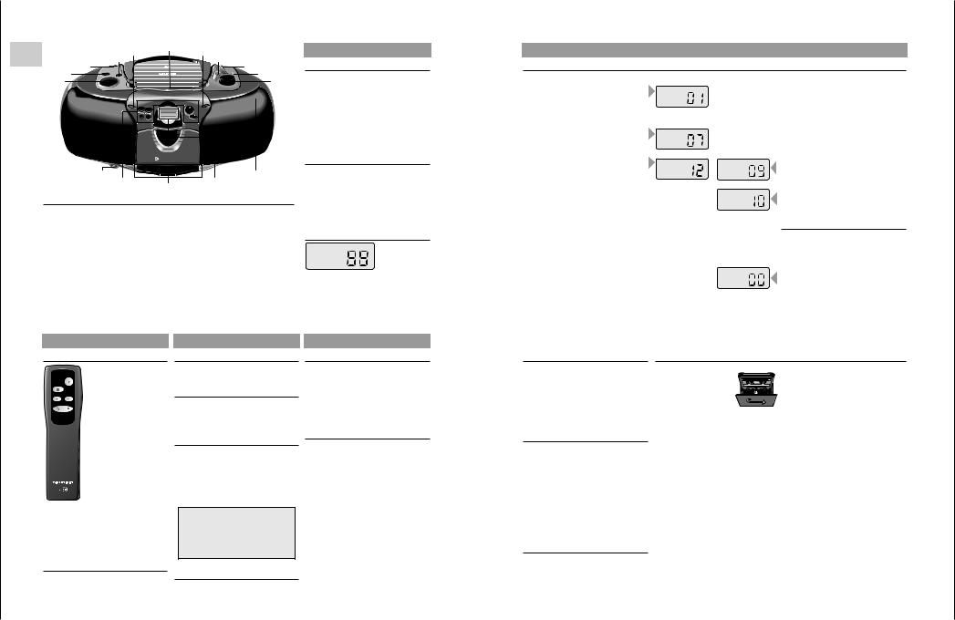
Oberund Vorderseite (die Abbildung zeigt: RR 650 CD)
VOLUME |
– zum Einstellen der Lautstärke |
|
UBS |
– ein/aus des ULTRA BASS SYSTEM |
|
FUNCTION |
– CD: |
zum Umschalten auf CD-Betrieb/Einschalten |
–TAPE/OFF: zum Umschalten auf Cassettenbetrieb/Ausschalten
–RADIO: zum Umschalten auf Radiowiedergabe/Einschalten
SURROUND SOUND |
– einund ausschalten des Surround-sound-Effektes (nur RR 650 CD) |
REMOTE SENSOR |
– zur Empfangen der Fernbediensignale (nur RR 650 CD) |
OPEN/CLOSE |
– zum Öffnen der CD-Deckels |
POWER 6 |
– leuchtet auf, wenn das Gerät eingeschaltet ist |
BAND |
– zum Wählen zwischen FM, MW, und LW |
SCALE |
– Abstimmskala |
FM STEREO 6 |
– leuchtet auf, wenn ein UKW-Stereo-Sender empfangen wird |
TUNING |
– zum Abstimmen auf einen Radiosender |
p– Buchse für Stereo-Kopfhörer
MIC |
– eingebautes Mikrophon unter dem Lautsprechergitter |
BEDIENELEMENTE
CD Control
SKIP/SEARCH
/5 6/§ – zum Überspringen von Stücken und zum Suchen in Vorwärtsoder Rückwärtsrichtung
REPEAT |
– zum Wiederholen eines |
|
Titels/aller Titel |
PROG. |
– zum Programmieren von Titeln |
|
im Speicher |
PLAY/PAUSE 2;– zum Starten/Unterbrechen der Wiedergabe
STOP 9 |
– zum Stoppen der Wiedergabe |
Cassette Control
0– Starten der Aufnahme
B– Starten der Wiedergabe
Q– schneller Rücklauf
R– schneller Vorlauf
9// |
– Stoppen des Bandlaufs und |
|
Öffnen des Cassettenfacks |
;– unterbrechen der Wiedergabe/Aufnahme
CD Display
PROGRAM REPEAT 1
PLAY
PAUSE
PROGRAM: Abspielen des Programms PLAY: Wiedergabe
PAUSE: PAUSE
REPEAT 1: Wiederholung eines Stücks REPEAT: Wiederholung aller Stücke
CD-SPIELER
Abspielen einer CD
•Zum Starten des Abspielens auf PLAY/PAUSE 2; drücken.
–Sobald das Abspielen beginnt, erscheinen 'PLAY' und die Nummer des laufenden Stücks.
•Den Ton mit den Reglern VOLUME, UBS und
SURROUND SOUND (nur RR 650 CD) einstellen.
•Für kurzzeitige Unterbrechungen auf
PLAY/PAUSE 2; drücken.
– Im Anzeigefeld erscheint das Zeichen 'PAUSE'.
• Zum Fortsetzen der Wiedergabe die Taste |
PLAY |
PLAY/PAUSE 2; erneut drücken. |
PAUSE |
• Zum Stoppen auf STOP 9 drücken.
–Das Display zeigt die Anzahl der Titel auf der CD.
–Der CD-Spieler geht ebenfalls in Stellung STOP:
–wenn Sie auf OPEN/CLOSE drücken;
–wenn das Ende der CD erreicht wird;
–wenn die Batterien ausgehen oder bei anderen Stromunterbrechungen.
•Zum Herausnehmen der CD öffnen Sie den Deckel durch Drücken der OPEN/CLOSE-Taste.
REPEAT 1
PLAY
REPEAT
PLAY
Rasches Suchen einer Passage
•/5 gedrückt halten, um in Richtung Plattenanfang zu suchen.
•6/§ gedrückt halten, um in Richtung Plattenende zu suchen.
Hinweis:
Dies ist ein 'hörbares Suchen'.
Während des Suchens wird die Lautstärke reduziert und nach dem Loslassen der Taste wird die Lautstärke auf ihren normalen Wert zurückgestellt.
Wiederholung eines Titels
•Durch einmaliges Drücken von REPEAT wird ein Musiktitel wiederholt.
– Im Anzeigefeld erscheint: 'REPEAT 1'
Wiederholung der CD
•Durch nochmaliges Drücken von REPEAT werden alle Musiktitel wiederholt.
– Im Anzeigefeld erscheint: 'REPEAT'
•Um den REPEAT-Modus auszuschalten, drücken Sie die Taste REPEAT erneut.
•Den CD-Deckel erst öffnen wenn sich der CDSpieler in Stellung STOP befindet.
Wahl eines anderen Titels während der Wiedergabe
•Taste /5oder 6/§drücken, bis die Nummer des gewünschten Titels im Anzeigefeld erscheint.
–Die Wiedergabe wird unterbrochen, und kurz danach beginnt die Wiedergabe des gewählten Stücks.
Beginnen mit einem bestimmten Titel
•Taste /5oder 6/§drücken, bis die Nummer des gewünschten Titels im Anzeigefeld erscheint.
•Taste PLAY/PAUSE 2; drücken.
–Die Wiedergabe beginnt beim Titel mit der eingegebenen Nummer.
Programmieren
Sie können maximal 21 Titel in jeder beliebigen Reihenfolge speichern. Beim Versuch mehr als 21 Titel zu speichern, wird die Programmierfunktion von Anfang an wiederholt.
Speichern eines Programms
•In Stellung STOP, drücken Sie die Taste PROG.. Auf dem Display erscheint die Angabe '00'.
•Wählen Sie den gewünschten Titel mit den Tasten /5 oder 6/§.
•Speichern Sie diese Nummer durch Drücken der PROG.-Taste.
•Wählen und speichern Sie in dieser Weise alle gewünschten Titel.
BEDIENELEMENTE KLANGREGULIERUNG
Fernbedienung (nur RR 650 CD)
|
Batteriewechsel |
|
Läßt die Reichweite Ihres IR-Gebers |
|
nach oder lassen sich einzelne |
PLAY |
Funktionen nicht mehr ausführen, |
STOP |
sollten Sie die Batterien |
PREV. NEXT |
auswechseln. |
|
Verwendeter Batterietyp 2x Micro |
VOLUME
1,5 Volt LR03, Größe AAA. Öffnen Sie zum Batteriewechsel den Deckel des Batteriefaches auf der Rückseite des Gebers. Achten Sie auf die richtige Polung der Batterien (Markierung im Batteriefach beachten).
Umwelt-Hinweis: Denken Sie beim Batteriewechsel daran: Batterien sind Sondermüll.
PLAY 2 – Starten/Unterbrechen der Wiedergabe
STOP 9 – Stoppen der Wiedergabe
PREV. ¡ – zum Überspringen von Stücken und zum Suchen in Rückwärtsrichtung
NEXT ™ – zum Überspringen von Stücken und zum Suchen in Vorwärtsrichtung
– VOLUME + – zum Einstellen der Lautstärke
Rückseite
FM MONO/STEREO / BEAT CUT:
–Wenn der BAND-Schalter auf FM steht: Auswahl zwischen FM STEREO und FM MONO
–Wenn der BAND-Schalter auf MW/LW steht: zum Unterdrücken eventueller Pfeifgeräusche bei MW(AM)-Aufnahmen
AC MAINS: Netzanschlußbuchse
Volume
•Stellen Sie die gewünschte Lautstärke mit dem VOLUME-Regler ein.
UBS (Ultra Bass System)
•Drücken Sie die Taste UBS, um die Baßtone hervorzuheben:
w UBS AUS x UBS EIN
Surround Sound (nur RR 650 CD)
Diese Funktion erstellt einen zusätlichen 3-dimen- sionalen Effekt des Stereoklangs, der von den Lautsprechern ausgetauscht wird.
•Drücken Sie SURROUND SOUND, um diesen Effekt ein-und auszuschalten.
w SURROUND SOUND AUS x SURROUND SOUND EIN
Hinweis:
Die Klangregler können bei der Wiedergabe von Radio, CD oder Cassette verwendet werden.
Jedoch haben sie keinen Einfluß auf die Cassettenaufnahme.
Kopfhörerbuchse p
• Sie können einen Stereo-Kopfhörer mit 3,5 mm Stecker an die Buchse p anschließen.
– Die Lautsprecher werden damit abgeschaltet.
RADIO
Radioantennen
–Bei UKW-Empfang (FM) die Teleskopantenne herausziehen und durch Neigen und Drehen ausrichten. Bei zu starkem UKW-Signal (in Sendernähe) empfiehlt es sich die Antenne einzuschieben.
–Für MW/LW-Empfang hat das Gerät eine eingebaute Antenne. Die Teleskopantenne kann also eingeschoben bleiben. Zum Ausrichten der Antenne das ganze Gerät drehen.
Rundfunkempfang
•Den FUNCTION-Schalter auf RADIO stellen.
–Die Einschaltanzeige POWER 6 leuchtet auf.
•Den Ton mit den Reglern VOLUME, UBS und
SURROUND SOUND (nur RR 650 CD) einstellen.
•Sie können einen Stereo-Kopfhörer mit 3,5 mm Stecker an die Buchse p anschließen.
–Die Lautsprecher werden damit abgeschaltet.
•Den Wellenbereich mit dem BAND-Schalter wählen.
•Mit dem TUNING-Knopf auf den Sender abstimmen.
–Wenn die Angabe FM STEREO 6 erscheint, empfangen Sie einen UKW-Stereo-Sender.
•Treten bei UKW-Stereo-Empfang aufgrund einer nicht ausreichenden Signalstärke Störungen auf, können diese unterdrückt werden, indem
FM MONO/STEREO auf FM MONO geschaltet wird.
–Die FM STEREO-Anzeige 6 erlischt und der UKW-Sender wird in Mono wiedergegeben.
•Das Gerät ist ausgeschaltet, wenn sich der FUNCTION-Wahlschalter in der Position TAPE befindet und keine Tasten gedrückt sind.
–Die Einschaltanzeige POWER 6 erlischt.
CD-SPIELER |
|
CASSETTENDECK |
Kontrolle des Programms
•In Stellung STOP, wenn Sie wiederholt die Taste PROG. drücken, zeigt das Display nacheinander alle gespeicherten Stücknummern in Reihenfolge.
Titel dem Programm hinzufügen
•Drücken Sie mehrmals PROG. bis im Display '00' erscheint.
•Nun können Sie zu der aktuellen Reihenfolge, wie oben beschrieben, weitere Titel speichern (bis zu 21).
Abspielen des Programms
•Drücken Sie einmal PROG., um den ersten Titel des Programms anzeigen zu lassen.
•Taste PLAY/PAUSE 2; drücken.
–Das Abspielen beginnt mit dem ersten Programmtitel.
–Im Anzeigefeld erscheint: 'PROGRAM PLAY'
–Nach dem letzten Titel wird die Wiedergabe gestoppt.
–Das Display zeigt die Anzahl der Titel auf der CD.
Hinweise:
•Sie können die Wiedergabe durch Drücken der Taste STOP 9 beenden.
•Während der Wiedergabe eines Programms können mit den Tasten /5 oder 6/§ die gewünschten programmierten Titel angewählt werden.
Löschen eines Programms
•Drücken Sie STOP 9 um die Wiedergabe des Programms zu beenden.
•Der Inhalt des Programms wird gelöscht:
–durch Öffnen des CD-Fachs mit der Taste
OPEN/CLOSE;
–wenn der FUNCTION-Schalter betätigt wird;
–wenn die Batterien ausgehen oder bei anderen Stromunterbrechungen.
Aufnahme
• Öffnen Sie den Cassettenhalter mit 9//.
• Legen Sie eine Cassette ein.
• Beim Mithören der Aufnahme, den Ton mit den Reglern
VOLUME, UBS und SURROUND SOUND (nur
RR 650 CD) einstellen.
Die Stellung dieser Regler hat keinen Einfluß auf die Aufnahme.
• Zum Aufnahmestart auf 0 drücken (die Taste B rastet automatisch mit ein).
–Wenn das Bandende erreicht ist, werden die Recorder-Tasten freigegeben.
•Zum Unterbrechen der Aufnahme die Taste ; drücken.
•Zum Fortsetzen der Aufnahme die Taste ; erneut drücken.
•Die Taste 9// drücken, wenn die Aufnahme vor Erreichen des Bandendes gestoppt werden soll. Durch erneutes Drücken dieser Taste öffnet sich das Cassettenfach.
•Das Gerät ist ausgeschaltet, wenn sich der FUNCTION-Wahlschalter in der Position TAPE befindet und keine Tasten gedrückt sind.
– Die Einschaltanzeige POWER 6 erlischt.
CD Synchro – Aufnahme vom CD-Spieler
•Den FUNCTION-Schalter auf CD stellen.
•Sie brauchen den CD-Spieler nicht separat zu
starten: sobald Sie auf 0 drücken, startet der CD-Spieler automatisch.
–Steht der CD-Spieler in Stellung STOP, startet die Aufnahme vom Anfang der CD (oder vom Anfang des gespeicherten Programms).
•Um eine Aufnahme in der Mitte eines Stücks zu starten, beginnen Sie die CD-Wiedergabe wie gewohnt.
•Sobald die gewünschte Passage erreicht ist, drücken Sie auf Pause und anschließend auf 0, um die Aufnahme zu starten.
Aufnahme vom Radio
•Den FUNCTION-Schalter auf RADIO stellen.
•Mit dem BAND-Schalter den Wellenbereich wählen.
•Mit dem TUNING-Einsteller auf den gewünschten Radiosender abstimmen.
•Bei Aufnahme von UKW-Sendern den Schalter FM MONO/STEREO auf die gewünschte Position stellen.
•Wenn während der Aufnahme eines MW/LWSenders Pfeifgeräusche zu hören sind, können diese unterdrückt werden, indem der Schalter BEAT CUT auf die andere Position gestellt wird.
Mono-Aufnahme vom eingebauten Mikrophon
•Den FUNCTION-Schalter auf TAPE stellen.
•Den VOLUME-Regler auf Null stellen (ein Mithören während Mikrophonaufnahmen ist nicht möglich).
•Um eine gute Aufnahme zu gewährleisten, sollte ein Abstand von 30 – 100 cm zum Mikrofon eingehalten werden.
Section General / Teil Allgemeiner
CD 650 RR / CD 620 RR

Service GRUNDIG
5 - 1
Operating Instructions
Note: This chapter contains excerpts from the operating instructions. For further particulars please refer to the appropriate user instructions the part number of which is indicated in the relevant spare parts list.
GB |
|
|
REMOTE |
OPEN/CLOSE |
|
|
SURROUND |
SENSOR |
|
POWER 6 |
|
|
|
SOUND |
|
|
BAND |
|
FUNCTION |
|
|
|
SCALE |
|
UBS |
UBS |
|
|
FM STEREO 6 |
|
|
|
CD SYNCHRO START RECORDING |
||
|
VOLUME |
|
|
|
TUNING |
|
|
|
|
RR 6 50 CD RADI OCASSETTE RECORDER WITH CD |
|
PLAY PAUSE |
SKIP / SEARCH |
POWER
REPEAT |
PROG. |
STOP |
PLAYBACK/ |
REMOTE |
|
RECORD 2 |
CONTROL |
|
|
RR 650 CD RADIO CASSETTE RECORDER WITH CD |
p |
MIC |
CD Control |
CD Display |
|
Cassette Control |
Top and front panel (the illustration shows: RR 650 CD)
VOLUME |
– to adjust the volume |
|
UBS |
– to switch the ULTRA BASS SYSTEM on and off |
|
FUNCTION |
– CD: |
to switch to CD mode / Power On |
–TAPE/OFF: to switch to TAPE mode / Power Off
–RADIO: to switch to RADIO mode / Power On
SURROUND SOUND |
– to switch the surround sound effect on and off (only RR 650 CD) |
REMOTE SENSOR |
– to receive the remote signals (only RR 650 CD) |
OPEN/CLOSE |
– to open the CD door |
POWER 6 |
– lights up when the unit is on |
BAND |
– to select between FM, MW, and LW waveband |
SCALE |
– tuning dial scale |
FM STEREO 6 |
– lights up when receiving FM stereo stations |
TUNING |
– to tune to a radio station |
MIC |
– microphone under the speaker grill |
p– connection for headphones
CONTROLS
CD Control
SKIP/SEARCH |
|
/5 6/§ |
– to skip and search |
|
backward/forward |
REPEAT |
– to repeat one/all tracks |
PROG. |
– to programme track numbers |
|
in the memory |
PLAY/PAUSE 2; |
– to start and interrupt playback |
STOP 9 |
– to stop playback |
Cassette Control
0– to start recording
B– to start cassette playback
Q– fast rewind
R– fast forward
9// |
– to stop and eject the cassette |
;– to interrupt playback/recording
CD Display
PROGRAM |
REPEAT 1 |
PLAY |
|
PAUSE |
|
PROGRAM: |
programme playback |
PLAY: |
PLAY |
PAUSE: |
PAUSE |
REPEAT 1: |
repeat one |
REPEAT: |
repeat all |
CD PLAYER
Playing a CD
• Press PLAY/PAUSE |
|
|
– |
The display |
|
• Adjust the sound |
PLAY |
|
|
SURROUND SOUND (only RR 650 CD) controls. |
|
• For brief interruptions, press PLAY/PAUSE 2;. |
|
|
– |
'PAUSE' appears on the display. |
|
• To resume playback, press PLAY/PAUSE 2; |
PLAY |
|
|
again. |
PAUSE |
• To stop playback, press STOP 9.
–The total number of tracks will then appear on the display.
–The CD player also goes to position STOP:
–by pressing OPEN/CLOSE;
–when the end of the CD is reached;
–if the batteries run down or if the power supply is interrupted.
•To take out the CD, open the CD door by pressing OPEN/CLOSE.
•Open the CD door only if the CD-player is in position STOP.
Selecting another track during play
•Press /5 or 6/§ until the required track number appears in the display.
– The selected track begins to play.
Starting with a particular track
•Press /5 or 6/§ until the required track number appears in the display.
•Press PLAY/PAUSE 2;.
– Play starts from the selected track.
REPEAT 1
PLAY
REPEAT
PLAY
Searching for a passage during play
•Hold /5 down to search backwards to the beginning.
•Hold 6/§ down to search forwards to the end.
Note:
This function can be described as “audibly” searching for a title.
During the search, volume is reduced and returns to its adjusted level as soon as the button is released.
Repeating a track
• By pressing REPEAT once, one track is repeated.
– The display shows: 'REPEAT 1'
Repeating the CD
•By pressing REPEAT once more, all tracks are repeated.
–The display shows: 'REPEAT'
•To switch the repeat mode off, press REPEAT one more time.
Programming
By programming the player you can play up to 21 tracks in any desired order. If you exceed the maximum of 21 tracks, the programme function will start again from the beginning.
Storing a programme
•In STOP mode, press PROG.. The display will show '00'.
•Select the first desired track using /5 or
6/§.
•Store this track by pressing PROG. again.
•Select and store in this way all desired titles.
CONTROLS
Remote control (only RR 650 CD)
PLAY
STOP
PREV. NEXT
VOLUME
Changing the batteries
If the range of your infrared remote control seems to decrease, or if certain individual functions can no longer be carried out, you should replace the batteries.
Two mignon 1.5 Volt LR03 size AAA are required.
To change the batteries, open the compartment on the back of the remote control. Ensure that the batteries are inserted properly (note the markings in the compartment).
And in the interest of the environment: Remember that batteries must always be disposed of properly.
PLAY 2 – to start and interrupt CD playback STOP 9 – to stop CD playback
PREV. ¡ – to skip and search backward NEXT ™ – to skip and search forward
– VOLUME + – to adjust the volume
Back panel
FM MONO/STEREO / BEAT CUT:
–When BAND switch is in FM:
to select between FM STEREO and FM MONO
–When BAND switch is in MW/LW:
for eliminating possible whistle tones during MW/LW recordings
AC MAINS: Socket for mains lead.
SOUND CONTROL
Volume
•Adjust the volume to the desired level with the VOLUME control.
UBS (Ultra Bass System)
•Press UBS to enhance the bass response: w UBS OFF
x UBS ON
Surround Sound (only RR 650 CD)
This feature creates an additional 3-D effect from stereo sound which is relayed by the speakers.
•Press SURROUND SOUND to switch this effect on and off
w SURROUND SOUND OFF x SURROUND SOUND ON
Note:
The sound controls can be used with radio, CD or cassette playback.
However, they have no effect on cassette recording.
Stereo headphone socket p
•You may connect stereo headphones having a 3.5 mm plug to the jack p.
– Inserting the plug will disconnect the speakers.
RADIO
Radio aerials
–For FM, pull out the telescopic aerial. To improve FM-reception, incline and turn the aerial. Reduce its length if the FM-signal is too strong (very close to a transmitter).
–For MW/LW, the set is provided with a built-in aerial, so the telescopic aerial is not needed. Direct the aerial by turning the whole set.
Radio reception
•Set the FUNCTION switch to RADIO.
– The POWER indicator 6 lights up.
•Adjust the sound using the VOLUME, UBS and
SURROUND SOUND (only RR 650 CD) controls.
•You may connect stereo headphones having a 3.5 mm plug to the jack p.
– Inserting the plug will disconnect the speakers.
•Select the wave band using the BAND selector.
•Tune to a desired radio station using the TUNING control.
–When FM STEREO 6 appears, you are receiving a FM stereo transmitter.
•A disturbing noise, due to a weak FM stereo signal, can be suppressed by setting
FM MONO/STEREO to FM MONO.
–The FM STEREO indication 6 goes out and you will hear the FM station in mono.
•The set is switched off when the FUNCTION switch is in the TAPE position and no buttons are pressed.
–The POWER indicator 6 goes out.
CD PLAYER |
|
CASSETTE DECK |
Checking the programme
•From the STOP position, press PROG. repeatedly: the display shows in sequence all programmed track numbers.
Adding tracks to the programme
•Press PROG. repeatedly until the display shows '00'.
•You can now add tracks to the sequence as described above (up to 21).
Playing a programme
•Press PROG. once to show the first track of the programme.
•Press PLAY/PAUSE 2;.
–Play starts with the first track of the programme.
–The display shows 'PROGRAM PLAY'
–After the last track playback stops.
–The total number of tracks will then appear on the display.
Note:
•Press STOP 9 to stop playback.
•While playing a programme, it is possible to use/5 or 6/§ to select the desired programmed tracks.
Erasing a programme
•Press STOP 9 to stop playback.
•You can then erase the programme:
–by opening the CD door using OPEN/CLOSE;
–if you move the FUNCTION selector;
–if the batteries are exhausted or if the power supply is interrupted in another way.
Cassette recording
• Press 9// to open the cassette holder.
• Insert the cassette.
• When monitoring during recording, adjust the sound using the controls VOLUME,
UBS and SURROUND SOUND (only RR 650 CD).
These controls do not affect the recording.
•Start recording by pressing 0.
(the B button is automatically also pressed).
–When the end of the tape is reached, the recorder buttons are released.
•To interrupt recording, press ;.
•To continue recording, press ; again.
•Press 9// if you want to stop recording before the end of the tape.
On pressing again, the cassette holder will open.
•The set is switched off if the FUNCTION switch is in position TAPE and no buttons are pressed.
– The POWER indicator 6 goes out.
Recording from the CD-player (CD synchro recording)
•Set the FUNCTION switch to CD.
•It’s not necessary to start the CD player se-
parately: by pressing 0 the CD player starts automatically.
–If the CD player is in STOP position, recording will start from the beginning of the CD (or from the beginning of the programmed selection).
•To start a recording in the middle of a track, play the CD in the normal way.
•As soon as the desired passage is reached, pause the CD and then start recording by pressing 0.
Recording from the radio
•Set the FUNCTION selector to RADIO.
•Select the wave band using the BAND switch.
•Tune to desired radio station using the TUNING control knob.
•In case of FM radio recordings, set the FM MONO/STEREO switch to the desired position.
•If during the recording of an MW/LW station, a whistling sound is heard, this sound can be suppressed by setting the BEAT CUT switch to another position.
Mono recording from the built-in microphone
•Set the FUNCTION switch to TAPE
•Set the VOLUME control to the minimum volume level (during microphone recording , monitoring is not possible).
•To ensure a clear recording, the distance to microphone should be 30 – 100 cm.
CD 650 RR / CD 620 RR
Section General / Teil Allgemeiner
Allgemeiner Teil / General Section |
RR 620 CD / RR 650 CD |
Ausbauhinweise
Allgemeines zum mechanischen Teil.
Alle Schrauben, die in Kunststoff eingedreht werden, sollten zuerst soweit gegen den Uhrzeigersinn gedreht werden, bis Sie merken, die Schraube hat den Gewindeanfang gefunden. Erst dann ist die Schraube festzudrehen. Dadurch wird vermieden, daß ein neues Gewinde in den Kunststoff geschnitten wird und der Halt der Schraube verlorengeht.
Ist es erforderlich, lackgesicherte Schrauben zu lösen, müssen diese nach Abschluß der Reparatur wieder verlackt werden.
Magnetische Werkzeuge dürfen nicht in die Nähe der Magnetköpfe gebracht werden.
Nach jeder Reparatur am Cassettenlaufwerk sind die Köpfe, die Tonwelle und die Andruckrolle mit Spiritus oder Reinigungsbenzin zu reinigen.
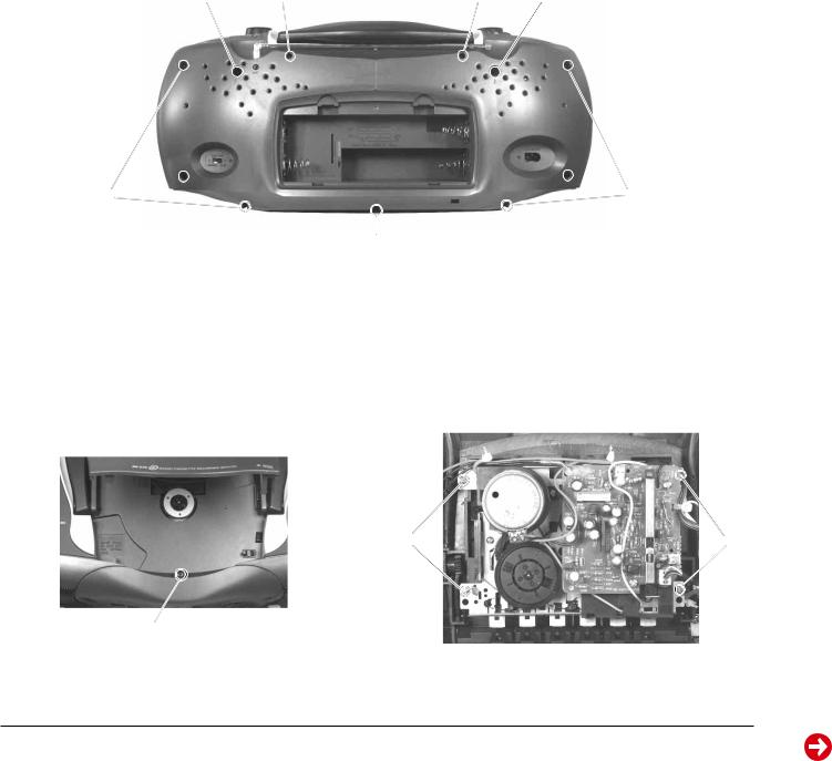
1.Gehäusevorderteil abnehmen
-2 Schrauben A (lang) und 7 Schrauben B (kurz) herausdrehen
(Fig. 1).
-Schraube C im CD-Fach (Fig. 2) herausdrehen.
-Gehäusevorderteil nach vorne abnehmen.
-Bei Bedarf Steckverbindungen abziehen.
Disassembly Instructions
General Notes on the Mechanical Section.
All the screws which are screwed into plastic parts should be turned counter clockwise first until you notice that the screw has found the first thread. Then tighten the screw. This preventive measure ensures that no new threads are cut into the plastic material thus deteriorating the good fit of the screw.
If screws secured with lacquer have to be loosened, they must be resecured in the same manner when the repair is completed.
Magnetic tools shall not be brought near the magnetic heads.
Each time repair work has been carried out on the cassette drive mechanism, clean the heads, the capstan and the rubber pinch roller with spirit or cleaning benzine.
1.Removing the Cabinet Front
-Undo 2 screws A (long) and 7 screws B (short) (Fig. 1).
-Undo the screw C in the CD compartment (Fig. 2).
-Remove the front of the cabinet towards the front.
-Disconnect the plug-in connections if necessary.
A F F A
B
 B
B
B
Fig. 1
2.Cass.-Laufwerk ausbauen, (Fig. 3)
-Gehäusevorderteil abnehmen (siehe Pkt. 1).
-4 Schrauben D herausdrehen.
-Cassettenfachdeckel durch Drücken der Taste STOP/EJECT öffnen.
-Laufwerk herausnehmen.
-Eventuell Kabelbinder lösen.
2.Dismantling the Cassette Drive Mechanism, (Fig. 3)
-Remove the cabinet front (see para 1).
-Undo 4 screws D.
-Open cassette compartment lid by pressing the buttton STOP/ EJECT.
-Take out the cassette drive mechanism.
-Eventually loosen the cable ties.
D D
C
Fig. 2 |
Fig. 3 |
1 - 6 |
GRUNDIG Service |
RR 620 CD / RR 650 CD |
Allgemeiner Teil / General Section |
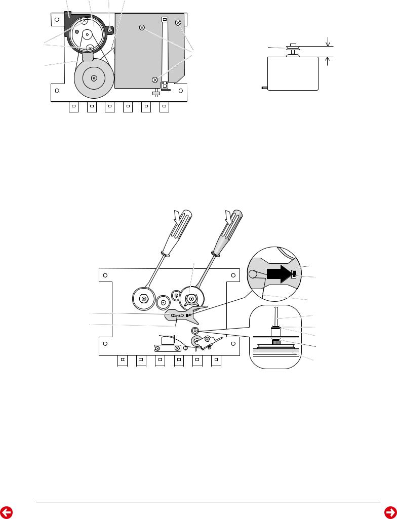
HK G M
J |
SWITCHR/P |
|
CASS. PCB |
I |
|
|
START |
|
SWITCH |
E |
L |
7,6 mm |
MOTOR |
K |
Fig. 4
3. Motor ausbauen, (Fig. 4 und 5)
-Laufwerk ausbauen (siehe Pkt. 2).
-Schraube G herausdrehen.
-Motorhalter H (mit Motor) und Riemen I abnehmen.
-Zwei Schrauben Jherausdrehen, Motor K(Einbaulage beachten) abnehmen und Motorzuleitungen ablöten (evtl. markieren).
-Vor dem Zusammenbau ist der Abstand zwischen der Oberkante der Riemenscheibe L und dem Motor K zu überprüfen (Fig. 5).
Fig. 5
3. Removing the Motor, (Figs. 4 and 5)
-Remove the drive mechanism (see para 2).
-Undo the screw G.
-Remove the motor holder H (with the motor) and the belt I.
-Undo two screws J, take out the motor K(note the motor mounting position) and unsolder the motor connecting leads (mark them, if necessary).
-Before refitting the motor, check the distance between the upper edge of the pulley L and the motor K (Fig. 5).
U |
S |
|
|
A |
R |
|
T |
S |
O |
T |
N |
|
|
|
Q |
|
P |
|
O |
4. Schwungscheibe ausbauen
-Laufwerk ausbauen (siehe Pkt. 2).
-3 Schrauben E(Fig. 4) herausdrehen und CASS. PCB abnehmen.
-Riemen M und I abnehmen (Fig. 4).
-Sperrscheibe N (Fig. 6) von der Tonwellenachse abziehen.
-Schwungscheibe Omit der Tonwelle aus dem Schwungscheibenlager herausnehmen. Achten Sie dabei auf die beiden Scheiben P und Q (Fig. 6).
-Neue Schwungscheibe einsetzen, danach Tonwelle mit Spiritus reinigen und in umgekehrter Reihenfolge zusammenbauen.
5. Vorlauf-Wickelteller ausbauen (Fig. 6)
-Laufwerk ausbauen (siehe Pkt. 2).
-Rastnase R in Pfeilrichtung A drücken und Hebel S abnehmen, achten Sie dabei auf die Schenkelfeder T.
-Vorlauf-Wickelteller U mit einem Schraubendreher abhebeln.
Fig. 6
4. Removing the Flywheel
-Remove the drive mechanism (see para 2).
-Undo 3 screws E (Fig. 4) and remove the CASS. PCB.
-Remove the drive belts M and I (Fig. 4).
-Remove the locking disc N (Fig. 6) from the capstan.
-Remove flywheel O complete with capstan from flywheel bearing.
Take care of the two washers P and Q (Fig. 6).
-Fit new flywheel, clean capstan in white spirit and reassemble in reverse order.
5. Dismantling of Spool Carrier -forward wind- (Fig. 6)
-Remove the drive mechanism (see para 2).
-Push the catch R in the direction of arrow A and take off lever S, take care of leg spring T.
-Lift off the spool carrier U(forward wind) by means of a screw driver.
GRUNDIG Service |
1 - 7 |

Allgemeiner Teil / General Section |
RR 620 CD / RR 650 CD |
6. Chassis ausbauen, (Fig. 1 und 7)
-Gehäusevorderteil abnehmen, (siehe Pkt. 1).
-2 Schrauben F herausdrehen (Fig. 1).
-Schraube V herausdrehen (Fig. 7).
-Chassis (mit Lautstärkereglerplatte, Tunerplatte, Bedienplatte, CDTeil) nach vorne herausnehmen.
-Bei Bedarf Steckverbindungen abziehen.
Bedienplatte |
Tunerplatte |
Chassisrahmen |
Control PCB |
Tuner PCB |
Chassis frame |
6. Removing the Chassis, (Fig. 1 and 7)
-Remove the cabinet front (see para 1).
-Undo 2 screws F (Fig. 1).
-Undo the screw V (Fig. 7).
-Remove the chassis towards the front (with volume control PCB, tuner PCB, control PCB, CD unit).
-Disconnect the plug-in connections if necessary.
a |
CD-Leiterplatte |
a |
|
|
|
|
CD PCB |
|
V
Fig. 7
7. CD-Laufwerk ausbauen
Bei Ausbau der CD-Lasereinheit muß vor Abziehen der Steckverbindungen eine Schutzlötstelle n auf der Leiterplatte der Lasereinheit angebracht werden, um eine Zerstörung der Laserdiode durch statische Aufladung zu vermeiden (Fig. 13).
-Chassis ausbauen (siehe Pkt. 6).
-4 Schrauben a (Fig. 8) herausdrehen.
-Steckverbindungen von der CD-Leiterplatte abziehen.
-CD-Leiterplatte abnehmen.
-4 Schrauben b herausdrehen (Fig. 9).
-CD-Laufwerk herausnehmen.
Achten Sie dabei auf die Puffer (Fig. 9) c (schwarz) und d (blau) Diese Puffer haben einen unterschiedlichen Auflagedruck
(schwarz = stärker, blau = schwächer).
a |
a |
|
Fig. 8 |
7. Removing the CD Mechanism
When removing the Laser pick-up, the pick-up PCB must be provided with a protective soldered joint n before unplugging the connectors to avoid damage to the Laser diode by static charges (Fig. 13).
-Remove the chassis (see para 6).
-Undo 4 screws a (Fig. 8).
-Unplug the connectors from the CD circuit board.
-Take out the CD circuit board.
-Undo 4 screws b (Fig. 9).
-Remove the CD mechanism.
Take care of the buffers c (black) and d (blue) Fig. 9. The buffer pressure is different (black = stronger, blue = weaker).
b |
b |
c |
d |
c |
d |
b |
b |
|
Fig. 9 |
1 - 8 |
GRUNDIG Service |
 Loading...