


|
|
|
|
|
TV |
|
Service Manual |
||
Chassis
P060L46M4W2
Cinemo 40
|
|
|
|
|
|
|
|
|
|
|
|
|
|
|
|
|
|
|
|
|
|
|
|
|
|
|
LXW 102-8735 REF |
GML5300 |
|
||||||||||||||||||||||||||||
|
|
|
|
|
|
|
|
|
|
|
|
|
|
|
|
|
|
|
|
|
|
|
|
|
|
|
|
|
Cinemo 46
|
LXW 117-8735 REF |
GML5400 |
|
||
|
|
|
Torreon 40
|
|
|
|
|
LXW 102-8790 REF |
GML5800 |
|
|
|
|
|
|
|
|
|
|
|
|
|
|
|
|
|
|
|
|
|
|
|
|
|
|
|
|
|
|
|
|
|
|
|
|
|
|
|
|
|
|
|
|
|
|
|
|
|
|
|
|
|
|
|
|
|
|
|
|
|
|
|
|
|
|
|
|
|
|
|
|
|
|
|
|
|
|
|
|
|
|
|
|
|
|
|
|
|
|
|
|
|
|
|
|
|
|
|
|
|
|
|
|
|
|
|
|
|
|
|
|
|
|
|
|
|
|
|
|
|
|
|
|
|
|
|
|
|
|
|
|
|
|
|
|
|
|
|
|
|
|
|
|
|
|
|
|
|
|
|
|
|
|
|
|
|
|
|
|
|
|
|
|
|
|
|
|
|
|
|
|
|
|
|
|
|
|
|
|
|
|
|
|
|
|
|
|
|
|
|
|
|
|
|
|
|
|
|
|
|
|
|
|
|
|
|
|
|
|
|
|
|
|
|
|
|
|
|
|
|
|
|
|
|
|
|
|
|
|
|
|
|
|
|
|
|
|
|
|
|
|
|
|
|
|
|
|
|
|
|
|
|
|
|
|
|
|
|
|
|
|
|
|
|
|
|
|
|
|
|
|
|
|
|
|
|
|
|
|
|
|
|
|
|
|
|
|
|
|
|
|
|
|
|
|
|
|
|
|
|
|
|
|
|
|
|
|
|
|
|
|
|
|
|
|
|
|
|
|
|
|
|
|
|
|
|
|
|
|
|
|
|
|
|
|
|
|
|
|
|
|
|
|
|
|
|
|
|
|
|
|
|
|
|
|
|
Zusätzlich erforderliche Unterlagen für den Komplettservice
Additionally required Service Documents for the Complete Service
Service
Manual
Sicherheit
Safety
Materialnr./Part No.
720108000001
Materialnummer/Part Number 720100523000 Änderungen vorbehalten/Subject to alteration TCC 1106 MP • Printed in Germany http://www.grundig.com

GRUNDIG Service |
Chassis P060L46M4W2 |
|
|
Es gelten die Vorschriften und Sicherheitshinweise gemäß dem Service Manual "Sicherheit", Materialnummer 720108000001, sowie zusätzlich die eventuell abweichenden, landesspezifischen Vorschriften!
The regulations and safety instructions shall be valid as provided by the "Safety" Service Manual, part number 720108000001, as well as the respective national deviations.
Inhaltsverzeichnis
|
Seite |
Allgemeiner Teil................................... |
1-2…1-12 |
Allgemeine Hinweise...................................................................... |
1-2 |
Technische Daten........................................................................... |
1-3 |
Bedienhinweise.............................................................................. |
1-5 |
Serviceund Sonderfunktionen.................................................... |
1-11 |
Platinenabbildungen |
|
und Schaltpläne.................................. |
2-1…2-34 |
Blockschaltplan.............................................................................. |
2-1 |
Netzteil........................................................................................... |
2-2 |
Haupt-Platte................................................................................... |
2-9 |
– VGA/HDMI-IN........................................................................... |
2-11 |
– IN/OUT..................................................................................... |
2-13 |
– Video-Konverter (UPD64015)................................................... |
2-14 |
– Prozessor (VCT49xyI).............................................................. |
2-16 |
– Scaler (MST5181).................................................................... |
2-18 |
– Speicher................................................................................... |
2-20 |
– Netzteil..................................................................................... |
2-22 |
– Video-Display-Prozessor (MDIN180)........................................ |
2-23 |
– Video-Speicher......................................................................... |
2-24 |
AV-Platte...................................................................................... |
2-25 |
– Buchsen................................................................................... |
2-26 |
– Tuner, SPDIF, NIMP.................................................................. |
2-27 |
– IN/OUT (CXA2069Q)................................................................ |
2-28 |
– Audio (MSP44xx)..................................................................... |
2-30 |
– Ton-Verzögerung (NSP-2100A)................................................ |
2-31 |
– Verstärker (TAS5112)............................................................... |
2-32 |
Buchsen-Platte............................................................................. |
2-33 |
Lautsprecherplatte....................................................................... |
2-34 |
LED/IR-Empfänger....................................................................... |
2-34 |
LED-/Lautsprecher-Platte............................................................. |
2-34 |
Keyboard...................................................................................... |
2-34 |
Explosionszeichnungen |
|
und Ersatzteillisten............................... |
3-1…3-5 |
Allgemeiner Teil
Allgemeine Hinweise
Achtung: ESD-Vorschriften beachten 
Vor dem Öffnen des Gehäuses zuerst den Netzstecker ziehen!
Leitungsverlegung
Bevor Sie Leitungen und insbesondere Masseleitungen lösen, muss die Leitungsverlegung zu den einzelnen Baugruppen beachtet werden. Nach erfolgter Reparatur ist es notwendig, die Leitungsführung wieder in den werkseitigen Zustand zu versetzen um evtl. spätere Ausfälle oder Störungen zu vermeiden.
Durchführen von Messungen
Bei Messungen mit dem Oszilloskop an Halbleitern sollten Sie nur Tastköpfe mit 10:1 -Teiler verwenden.Außerdem ist zu beachten, dass nach vorheriger Messung mit AC-Kopplung der Koppelkondensator des Oszilloskops aufgeladen sein kann.Durch die Entladung über das Messobjekt können Bauteile beschädigt werden.
Messwerte und Oszillogramme
Bei den in den Schaltplänen und Oszillogrammen angegebenen Messwerten handelt es sich um Näherungswerte!
Austausch der Haupt-Platte
Nach Austausch der Haupt-Platte müssen alle Einstellungen im Service Mode nach Tabelle "Grundeinstellwerte" (Punkte 1 und 2 im Kapitel
"Serviceund Sonderfunktionen" auf Seite 1-11) eingestellt werden.
Table of Contents
|
Page |
General Section................................... |
1-2…1-12 |
General Notes................................................................................ |
1-2 |
Technical Data................................................................................ |
1-3 |
Operating Hints.............................................................................. |
1-8 |
Service and Special Functions..................................................... |
1-11 |
Layout of PCBs |
|
and Circuit Diagrams.......................... |
2-1…2-34 |
Block Circuit Diagram..................................................................... |
2-1 |
Power Supply Board....................................................................... |
2-2 |
Main Board..................................................................................... |
2-9 |
– VGA/HDMI-IN........................................................................... |
2-11 |
– IN/OUT..................................................................................... |
2-13 |
– Video Converter (UPD64015)................................................... |
2-14 |
– Processor (VCT49xyI).............................................................. |
2-16 |
– Scaler (MST5181).................................................................... |
2-18 |
– Memory.................................................................................... |
2-20 |
– Power Supply........................................................................... |
2-22 |
– Video Display Processor (MDIN180)........................................ |
2-23 |
– Video Memory.......................................................................... |
2-24 |
AV Board...................................................................................... |
2-25 |
– Sockets..................................................................................... |
2-26 |
– Tuner, SPDIF, NIMP.................................................................. |
2-27 |
– IN/OUT (CXA2069Q)................................................................ |
2-28 |
– Audio (MSP44xx)..................................................................... |
2-30 |
– Sound Delay (NSP-2100A)...................................................... |
2-31 |
– Amplifier (TAS5112)................................................................. |
2-32 |
Socket Board................................................................................ |
2-33 |
Speaker Board............................................................................. |
2-34 |
LED/IR Receiver.......................................................................... |
2-34 |
LED/Speaker Board..................................................................... |
2-34 |
Keyboard...................................................................................... |
2-34 |
Exploded Views |
|
and Spare Parts Lists........................... |
3-1…3-5 |
General Section
General Notes
Attention: Observe the ESD safety regulations  Before opening the cabinet disconnect the mains plug!
Wiring
Before disconnecting any leads and especially the earth connecting leads observe the way they are routed to the individual assemblies. On completion of the repairs the leads must be laid out as originally fitted at the factory to avoid later failures or disturbances.
Carrying out Measurements
When making measurements on semi-conductors with an oscilloscope, ensure that the test probe is set to 10:1 dividing factor. If the previous measurement was made on AC input, please note that the coupling capacitor in the oscilloscope will be charged. Discharge via the item being checked can damage the components.
Measured Values and Oscillograms
The measured values given in the circuit diagrams and oscillograms are approximates!
Change of the Main Board
After changing the main board all settings in the service mode must be done according to the table "Basic Settings" (points 1 and 2 in chapter "Service and Special Functions" on page 1-11).
1 -
GRUNDIG Service |
Chassis P060L46M4W2 |
Technische Daten / Technical Data
|
Cinemo 40 LXW 102-8735 REF |
Cinemo 46 LXW 117-8735 REF |
Torreon 40 LXW 102-8790 REF |
|
Order No. |
G.ML 53-00 |
G.ML 54-00 |
G.ML 58-00 |
|
Destination |
D,GB,F,I,NL,DK,N,S,FIN,E,P,PL,CZ |
D,GB,F,I,NL,DK,N,S,FIN,E,P,PL,CZ |
D,GB,F,I,NL,DK,N,S,FIN,E,P,PL,CZ |
|
Approbations |
CE,I |
CE,I |
CE,I |
|
IM-Languages |
D, CH, F, I, E, P, NL, Nordic, PL, CZ, HR |
D, CH, F, I, E, P, NL, Nordic, PL, CZ |
D, CH, F, I, E, P, NL, Nordic, PL, CZ |
|
Remote control |
TP 170 C (black) |
TP 170 C (black) |
TP 170 C (black) |
|
EAN |
40 13833-60922 3 |
40 13833-60923 0 |
40 13833-60926 1 |
|
Color |
black |
black |
silver/black |
|
DISPLAY |
|
|
|
|
Panel |
40" / 102 cm Active Matrix TFT-LC-Display |
46" / 117 cm Active Matrix TFT-LC-Display |
40" / 102 cm Active Matrix TFT-LC-Display |
|
Display-Manufacturer |
Samsung LTA400WS-L02 |
Samsung LTA460WS-L03 |
Samsung LTA400WS-L02 |
|
Super High Speed PVA-Panel |
Super High Speed PVA-Panel |
Super High Speed PVA-Panel |
||
|
||||
16:9 wide-screen format |
[ |
[ |
[ |
|
Response time |
8ms |
8ms |
8ms |
|
Brightness |
500cd/m2 |
500cd/m2 |
500cd/m2 |
|
Contrast ratio (Panel) |
ca. 1.200:1 |
ca. 1.200:1 |
ca. 1.200:1 |
|
Viewing angle approx. |
178° vertical / 178° horizontal |
178° vertical / 178° horizontal |
178° vertical / 178° horizontal |
|
Physical display resolution max. pixel |
WXGA 1366 x 768 |
WXGA 1366 x 768 |
WXGA 1366 x 768 |
|
PICTURE |
|
|
|
|
Digital Reference Plus |
[ |
[ |
[ |
|
Motion Compensative Deinterlacing |
[ |
[ |
[ |
|
Motion Adaptive Deinterlacing |
[ |
[ |
[ |
|
Natural view HD Reference |
\ |
\ |
\ |
|
Full HD |
\ |
\ |
\ |
|
Line Flicker Reduction |
[ |
[ |
[ |
|
Digital Color Transition Improv. (DCTI) |
[ |
[ |
[ |
|
Digital Combfilter |
[ (3D) |
[ (3D) |
[ (3D) |
|
Digital Luminace Transition Improv. (DLTI) |
[ |
[ |
[ |
|
Picture Noise Reduction (DNR) |
[ |
[ |
[ |
|
CCS (Clear Color Screen) |
\ |
\ |
\ |
|
Preset picture modes |
4 Mode - Cool, Warm, Normal, User |
4 Mode - Cool, Warm, Normal, User |
4 Mode - Cool, Warm, Normal, User |
|
Picture Status Memory |
5 Mode - Dynamic, Standard, Mild, Game, User |
5 Mode - Dynamic, Standard, Mild, Game, User |
5 Mode - Dynamic, Standard, Mild, Game, User |
|
Aspect ratios (Format switching) |
Auto WSS, 4:3 / 14:9 / 16:9 / |
Auto WSS, 4:3 / 14:9 / 16:9 / |
Auto WSS, 4:3 / 14:9 / 16:9 / |
|
Zoom 1 / Zoom 2 / Spectacle |
Zoom 1 / Zoom 2 / Spectacle |
Zoom 1 / Zoom 2 / Spectacle |
||
|
||||
Blackline detection |
\ |
\ |
\ |
|
PIP |
1-Tuner PIP |
1-Tuner PIP |
1-Tuner PIP |
|
Multifold Tuner scan (Mosaic Picture) |
4 & 16-Freeze |
4 & 16-Freeze |
4 & 16-Freeze |
|
PAT: Split screen (PICTURE + TEXT) |
\ |
\ |
\ |
|
PAP: Double Window (PICTURE + PICTURE) |
[ |
[ |
[ |
|
P2AT: Double Window + TXT |
\ |
\ |
\ |
|
POP: PICTURE on PICTURE |
[ |
[ |
[ |
|
Picture freezing |
[ |
[ |
[ |
|
Zoom with point function |
\ |
\ |
\ |
|
Auto 16:9 selection via Scart |
[ |
[ |
[ |
|
Sharpness control |
[ |
[ |
[ |
|
Blue Background |
\ |
\ |
\ |
|
CHASSIS |
|
|
|
|
Progressive |
[ |
[ |
[ |
|
Tuner |
PLL frequency synthesizer tuning |
PLL frequency synthesizer tuning |
PLL frequency synthesizer tuning |
|
Keyboard |
7 keys: stand-by, menue, ± for programme, |
7 keys: stand-by, menue, ± for programme, |
7 keys: stand-by, menue, ± for programme, |
|
± for volume, input select |
± for volume, input select |
± for volume, input select |
||
|
1 - 3

GRUNDIG Service |
|
|
|
Chassis P060L46M4W2 |
|
|
|
|
|
|
Cinemo 40 LXW 102-8735 REF |
Cinemo 46 LXW 117-8735 REF |
|
Torreon 40 LXW 102-8790 REF |
ELECTRONIC |
|
|
|
|
Stand by indicator |
red LED |
red LED |
|
red LED |
EPG (Electronic Programme Guide) |
\ |
\ |
|
\ |
Easy Dialog |
\ |
\ |
|
\ |
Megalogic |
\ |
\ |
|
\ |
Manual & autom. labeling of prog. |
[ |
[ |
|
[ |
Programmable off timer |
[ |
[ |
|
[ |
Programmable on timer |
[ |
[ |
|
[ |
Intelligent channel search (Zapping funct.) |
\ |
\ |
|
\ |
Programme Edit |
[ |
[ |
|
[ |
Intelligent Programme Switch |
\ |
\ |
|
\ |
Auto switch off |
stand-by |
stand-by |
|
stand-by |
Program memory TV/AV (opt.) |
99 / 8 |
99 / 8 |
|
99 / 8 |
Teletext/Fasttext/Toptext |
[ / [ / [ |
[ / [ / [ |
|
[ / [ / [ |
Teletext options |
1000 pages |
1000 pages |
|
1000 pages |
Childlock |
[ |
[ |
|
[ |
Menue languages OSD |
13 languages, D, GB, F, I, E, P, NL, DK, FIN, N, S, PL, CZ |
|||
OSD-style |
Grundig-style |
Grundig-style |
|
Grundig-style |
SWAP (Recall function) |
[ |
[ |
|
[ |
Service mode |
[ |
[ |
|
[ |
Hotel mode |
\ |
\ |
|
\ |
TUNING |
|
|
|
|
Autom. Tuning System with country selection |
full automatic sorting |
full automatic sorting |
|
full automatic sorting |
Frequency Based Auto Search |
[ |
[ |
|
[ |
Automatic Micro-search |
\ |
\ |
|
\ |
Automatic Programming |
\ |
\ |
|
\ |
Manual fine tuning |
[ |
[ |
|
[ |
Direct channel selection |
[ |
[ |
|
[ |
Direct frequency selection |
[ |
[ |
|
[ |
TV-Norm |
PAL/SECAM/BG/DK/I/L'/L |
PAL/SECAM/BG/DK/I/L'/L |
|
PAL/SECAM/BG/DK/I/L'/L |
NTSC-Playback via Scart (3,58/4,43) |
[ |
[ |
|
[ |
Cable TV / Hyperband (S1-S41) |
[ |
[ |
|
[ |
AUDIO |
|
|
|
|
Mono/Stereo/Nicam |
[ / [ / [ |
[ / [ / [ |
|
[ / [ / [ |
AV Stereo |
[ |
[ |
|
[ |
Loudspeaker |
|
Super Woofer System SRS TruSurround XT Digital |
|
|
Virtual Dolby |
\ |
\ |
|
\ |
Magic Fidelity Sound System |
\ |
\ |
|
\ |
Matched Sound Delay (Lip synchronous) |
\ |
\ |
|
\ |
Subwoofer |
\ |
\ |
|
\ |
Dynamic Bass |
\ |
\ |
|
\ |
DSP (Digital Sound Processor) |
[ |
[ |
|
[ |
Balance Adjustment |
[ |
[ |
|
[ |
AVL (Audio Volume Level) |
[ |
[ |
|
[ |
PIP listening via Headphone.jack |
\ |
\ |
|
\ |
Equalizer |
7 Band |
7 Band |
|
7 Band |
Space Sound Effect |
[ |
[ |
|
[ |
Audio mode |
5 Mode - Flat, Music, Movie, Speech, User |
5 Mode - Flat, Music, Movie, Speech, User |
|
5 Mode - Flat, Music, Movie, Speech, User |
Audio amplifier |
2x 20W (RMS) |
2x 25W (RMS) |
|
2x 20W (RMS) |
DVB reception |
|
|
|
|
|
|
Retrofitting possible via Scart socket |
|
|
DVB-T/S/C |
|
DVB-T: DTR 1560 Micro |
|
|
|
DVB-S: DSR 1650 Micro |
|
||
|
|
|
||
|
|
DVB-C: DCB 1680 Micro |
|
|
POWER SUPPLY / CABINET |
|
|
|
|
Power voltage |
100 - 240V, 50/60Hz; in accordance to IEC 65 |
100 - 240V, 50/60Hz; in accordance to IEC 65 |
|
100 - 240V, 50/60Hz; in accordance to IEC 65 |
Range of regulation |
90-264V, 50/60Hz, in accordance to IEC 65 |
90-264V, 50/60Hz, in accordance to IEC 65 |
|
90-264V, 50/60Hz, in accordance to IEC 65 |
Power switch |
1-pole |
1-pole |
|
1-pole |
Integrated supply |
[ |
[ |
|
[ |
Plug-in AC adaptor |
\ |
\ |
|
\ |
Power consumption |
240W, stand-by < 3W in accordance to |
280W, stand-by < 3W in accordance to |
|
240W, stand-by < 3W in accordance to |
IEC 62087-2002 |
IEC 62087-2002 |
|
IEC 62087-2002 |
|
|
|
|||
Cabinet (WxHxD, cm) / Weight |
99,8 x 80,5 x 12,8 cm (30,6 cm with stand) / |
114,2 x 90,6 x 12,8 cm (35,5 cm with stand) / |
|
99,8 x 80,5 x 12,8 cm (30,6 cm with stand) / |
approx. 33,85 kg |
approx. 46,2 kg |
|
approx. 33,85 kg |
|
|
|
|||
FRONT PANEL CONNECTIONS |
|
|
|
|
Headphones |
\ |
\ |
|
\ |
Cinch-AV socket |
3 x Cinch - Video in, Audio in L/R (side) |
3 x Cinch - Video in, Audio in L/R (side) |
|
3 x Cinch - Video in, Audio in L/R (side) |
S-Video |
Hosiden (side) |
Hosiden (side) |
|
Hosiden (side) |
USB |
\ |
\ |
|
\ |
Digital Media Player |
\ |
\ |
|
\ |
YUV input / progressive |
Video-in: 3 x Cinch, Audio-in: 2 x Cinch (side) |
Video-in: 3 x Cinch, Audio-in: 2 x Cinch (side) |
|
Video-in: 3 x Cinch, Audio-in: 2 x Cinch (side) |
REAR PANEL CONNECTIONS |
|
|
|
|
Euro-AV-Socket AV1 |
CVBS in-/output, RGB input |
CVBS in-/output, RGB input |
|
CVBS in-/output, RGB input |
Euro-AV Socket AV2 |
CVBS in-/output |
CVBS in-/output |
|
CVBS in-/output |
Euro-AV Socket AV3 |
CVBS in |
CVBS in |
|
CVBS in |
S-Video |
\ |
\ |
|
\ |
Camera-AV |
\ |
\ |
|
\ |
Wireless |
\ |
\ |
|
\ |
YUV input / progressive |
Video-in: 3 x Cinch, Audio-in: 2 x Cinch |
Video-in: 3 x Cinch, Audio-in: 2 x Cinch |
|
Video-in: 3 x Cinch, Audio-in: 2 x Cinch |
PC-input |
Multisync WXGA |
Multisync WXGA |
|
Multisync WXGA |
PC-Audio in |
[ |
[ |
|
[ |
DVI |
\ |
\ |
|
\ |
HDMI |
2x |
2x |
|
2x |
HD ready including HDCP |
via HDMI |
via HDMI |
|
via HDMI |
Headphones |
\ |
\ |
|
\ |
Digital Audio out optical (SPDIF) |
[ |
[ |
|
[ |
Video out |
\ |
\ |
|
\ |
Audio out |
\ |
\ |
|
\ |
Antenna for terrestrial reception |
1 x Coaxial-socket for TV-tuner-in, according to DIN 45325 |
|||
DC-connector |
\ |
\ |
|
\ |
Power supply plug |
[ |
[ |
|
[ |
SUPPLIED ACCESSORIES |
|
|
|
|
Remote control (incl. battery) |
TP 170 C black, running change TP 170 C black glossy |
|||
Power cord |
[ (grounded) |
[ (grounded) |
|
[ (grounded) |
Cables |
\ |
\ |
|
\ |
Instruction manual |
[ |
[ |
|
[ |
Circuit diagram |
[ |
[ |
|
[ |
Wall fixture |
(V) 216 x (H) 688 |
(V) 216 x (H) 688 |
|
(V) 216 x (H) 688 |
Warning sticker in rear panel |
[ |
[ |
|
[ |
Warranty info |
[ |
[ |
|
[ |
1 - 4
Bedienhinweise Dieses Kapitel enthält Auszüge aus der Bedienungsanleitung.
Weitergehende Informationen entnehmen Sie bitte der gerätespezifischen Bedienungsanleitung, deren Materialnummer Sie in der entsprechenden Ersatzteilliste finden.
5 - 1
Service GRUNDIG
P060L46M4W2.22 Chassis Chassis
GRUNDIG Service |
ChassisChassisP060L46M4W2ChassisD-32IE1122. |
1 - 6
GRUNDIG Service |
Chassis P060L46M4W2 |
1 - 7
Operating Hints This chapter contains excerpts from the operating instructions.
For further particulars please refer to the appropriate user instructions the part number of which is indicated in the relevant spare parts list.
8 - 1
Service GRUNDIG
P060L46M4W2.22 Chassis Chassis
GRUNDIG Service |
Chassis P060L46M4W2Chassis 22. |
1 - 9
GRUNDIG Service |
Chassis P060L46M4W2 |
1 - 10
GRUNDIG Service Chassis P060L46M4W2
Serviceund Sonderfunktionen |
|
Service and Special Functions |
|
|
|||||
Service Mode aktivieren: Taste " i " –> Service Code "8500" |
Start of the Service Mode: Via " i " –> Service Code "8500" |
||||||||
Menü aufrufen: |
Taste P+ / P– –> Taste "OK" |
Call up the Menu: |
Press button P+ / P– –> button "OK" |
||||||
Einstellung verändern: |
Taste / bzw. "OK" |
|
Adjustment: |
Press button / |
or "OK" |
||||
Menü verlassen: |
Taste " i " |
|
Break of the Menu: |
Press button " i " |
|
|
|||
Service Mode beenden: Taste " i " nach Verlassen des Menü |
End the Service Mode: |
Press button " i " after break of Menu |
|||||||
1. Grundeinstellwerte |
|
|
|
|
1. Basic Settings |
|
|
|
|
Folgende Tabelle zeigt Grundeinstellungen im Service Mode. |
The following table shows basic settings in the service mode. |
||||||||
|
|
|
|
|
|
|
|
|
|
Menü |
|
Menüpunkt |
|
|
|
Einstellung |
|
|
|
|
|
Beschreibung |
Adjustment |
|
Hinweis |
|
|||
Menu |
|
Point of Menu |
|
|
|
||||
|
|
Description |
/ |
|
Hint |
|
|||
P+ / P– |
|
P+ / P– |
|
|
|
||||
|
|
|
|
OK |
|
|
|
||
|
|
|
|
|
|
|
|
|
|
|
|
|
|
|
|
|
|
|
|
|
|
AUTO-CUTOFF |
|
automatischer Schwarzabgleich / Auto cutoff Control |
siehe Punkt 2 |
|
|
|
|
|
|
|
see point 2 |
|
|
|
|||
|
|
|
|
|
|
|
|
|
|
|
|
R-DRIVE |
|
ohne Funktion |
|
– |
|
|
|
WHITE BALANCE |
|
G-DRIVE |
|
|
– |
|
|
|
|
|
|
without Function |
|
|
|
|
|||
(COMP1, COMP2) |
|
B-DRIVE |
|
|
|
– |
|
|
|
|
|
R-CUTOFF |
|
Cut off-Wert "rot" / Cut off value "red" |
128 |
|
|
|
|
|
|
G-CUTOFF |
|
Cut off-Wert "grün" / Cut off value "green" |
123 |
|
|
|
|
|
|
B-CUTOFF |
|
Cut off-Wert "blau" / Cut off value "blue" |
127 |
|
|
|
|
|
|
AUTO-CUTOFF |
|
automatischer Schwarzabgleich / Auto cutoff Control |
siehe Punkt 2 |
|
|
|
|
|
|
|
see point 2 |
|
|
|
|||
|
|
|
|
|
|
|
|
|
|
|
|
R-DRIVE |
|
ohne Funktion |
|
– |
|
|
|
WHITE BALANCE |
|
G-DRIVE |
|
|
– |
|
|
|
|
|
|
without Function |
|
|
|
|
|||
(PC-RGB) |
|
B-DRIVE |
|
|
|
– |
|
|
|
|
|
R-CUTOFF |
|
Cut off-Wert "rot" / Cut off value "red" |
131 |
|
|
|
|
|
|
G-CUTOFF |
|
Cut off-Wert "grün" / Cut off value "green" |
131 |
|
|
|
|
|
|
B-CUTOFF |
|
Cut off-Wert "blau" / Cut off value "blue" |
131 |
|
|
|
|
|
|
DUAL |
|
2-Kanal-Ton / Dual sound |
|
1 |
|
|
|
|
|
A2 STEREO |
|
A2 Stereo |
|
1 |
|
Ein / On = 1 |
|
|
|
DOLBY |
|
Dolby-Ton / Sound |
|
0 |
|
Aus / Off = 0 |
|
SOUND |
|
WOOFER |
|
Bass-Lautsprecher / Woofer sound |
0 |
|
|
|
|
|
|
SC PRESCALE |
|
Tonpegel-Euro-AV / Scart Output Level Control |
27 |
|
|
|
|
|
|
FM PRESCALE |
|
Tonpegel-FM / FM sound Level Control |
19 |
|
|
|
|
|
|
NICAM PRESCALE |
|
Tonpegel-Nicam / Nicam Sound Level Control |
70 |
|
|
|
|
|
|
|
|
|
|
|
|
|
|
|
|
CHINA |
|
China-Kanaltabelle / Channel Table |
0 |
|
|
|
|
|
|
TEXT |
|
TeleText |
|
1 |
|
|
|
|
|
TXT LIST MODE |
|
Teletext-List Betrieb / Mode |
|
1 |
|
Ein / On = 1 |
|
|
|
TXT-TOP |
|
TeleText TOP |
|
1 |
|
|
|
|
|
|
|
|
Aus / Off = 0 |
|
|||
|
|
|
|
|
|
|
|
|
|
|
|
TXT-ACMS |
|
TextText ACMS |
|
1 |
|
|
|
|
|
DTV-TXT |
|
DTV Text |
|
0 |
|
|
|
|
|
GAME |
|
Spiele / Game mode |
|
0 |
|
|
|
|
|
|
|
|
|
|
|
West Europe = 0 |
|
|
|
|
|
|
|
|
|
East Europe = 1 |
|
OPTION1 |
|
|
|
|
|
|
|
Turkey = 2 |
|
|
|
|
|
|
|
|
Czecho/Hungary = 3 |
|
|
|
|
|
|
|
|
|
|
Cyrillic1 = 4 |
|
|
|
|
|
|
|
|
|
Cyrillic2 = 5 |
|
|
|
|
|
|
|
|
|
Cyrillic3 = 6 |
|
|
|
TXT-LANG |
|
Teletext-Sprache / TeleText Language |
0 |
|
Turkey/Greek1 = 7 |
|
|
|
|
|
|
Turkey/Greek2 = 8 |
|
||||
|
|
|
|
|
|
|
|
Turkey/Greek3 = 9 |
|
|
|
|
|
|
|
|
|
Arab/France = 10 |
|
|
|
|
|
|
|
|
|
Arab/English = 11 |
|
|
|
|
|
|
|
|
|
Arab/Hebrew1 = 12 |
|
|
|
|
|
|
|
|
|
Arab/Hebrew2 = 13 |
|
|
|
|
|
|
|
|
|
Farsi/English = 14 |
|
|
|
|
|
|
|
|
|
Farsi/France = 15 |
|
|
|
|
|
|
|
|
|
Farsi All = 16 |
|
|
|
200PR |
|
200-Seiten-Programmierung / 200 Page Programming |
0 |
|
Ein / On = 1 |
|
|
|
|
|
|
Aus / Off = 0 |
|
||||
OPTION2 |
|
|
|
|
|
|
|
|
|
|
SYSTEM |
|
TV-Norm / RF System |
|
1 |
|
BG/I/DK/L = 1 |
|
|
|
|
|
|
|
|
||||
|
|
|
|
|
BG/I/DK/M = 2 |
|
|||
|
|
|
|
|
|
|
|
|
|
|
|
|
|
|
|
|
|
Englisch = 0 |
|
|
|
|
|
|
|
|
|
Deutsch = 1 |
|
|
|
|
|
|
|
|
|
France = 3 |
|
|
|
|
|
|
|
|
|
Italiano = 4 |
|
OPTION3 |
|
OSD LANGUAGE |
|
OSD-Sprache (Basis) / Default OSD Language |
1 |
|
Español = 5 |
|
|
|
|
|
Portuguêsa = 6 |
|
|||||
|
|
|
|
|
|
|
|
|
|
|
|
|
|
|
|
|
|
Dansk = 7 |
|
|
|
|
|
|
|
|
|
Svenska = 8 |
|
|
|
|
|
|
|
|
|
Suomi = 9 |
|
|
|
|
|
|
|
|
|
Nederlands = 10 |
|
POWER MODE |
|
POWER MODE |
|
Automatische Abschaltung / Auto Sleep Control |
OFF |
|
|
|
|
|
Auto Search |
|
ATS-Reset |
|
OFF |
|
|
|
|
|
|
|
|
|
|
|
|||
MICOM RESET |
|
|
|
µP-Reset |
|
|
|
|
|
|
|
DQSPH0 |
|
Speichertakt / Memory Clock Setting |
2 |
|
|
|
|
MEMORY-CLOCK SET |
|
DQSPH1 |
|
Speichertakt / Memory Clock Setting |
1 |
|
|
|
|
|
DQSPH2 |
|
Speichertakt / Memory Clock Setting |
2 |
|
|
|
||
|
|
|
|
|
|
||||
|
|
DQSPH3 |
|
Speichertakt / Memory Clock Setting |
1 |
|
|
|
|
PANEL TYPE |
|
PANEL1 |
|
LPL-Weißbalance / LPL White Balance Setting. |
eingebautes Display wählen |
|
|||
|
|
(WS-L01, WS-L02, WS-L03, WS-L11) |
select used display |
|
|
||||
|
|
|
|
|
|
||||
|
|
|
|
|
|
|
|
|
|
12 - 11
GRUNDIG Service |
|
|
|
Chassis P060L46M4W2 |
|
|
|
|
|
|
|
Menü |
Menüpunkt |
|
Einstellung |
|
|
Beschreibung |
Adjustment |
Hinweis |
|
||
Menu |
Point of Menu |
|
|||
Description |
/ |
Hint |
|
||
P+ / P– |
P+ / P– |
|
|||
|
OK |
|
|
||
|
|
|
|
|
|
|
|
|
|
|
|
|
Sharpness gain |
Schärfeeinstellung / Sharpness setting |
7 |
|
|
|
LTI gain |
Helligkeits-Übergangs-Verbesserung / LTI gain setting |
2 |
|
|
|
CTIB gain |
Farb-Übergangs-Verbesserung B / CTIB gain setting |
24 |
|
|
MDIN Reg1 |
CTIR gain |
Farb-Übergangs-Verbesserung R / CTIR gain setting |
24 |
|
|
Contrast |
Kontrast / Contrast setting |
512 |
|
|
|
|
|
|
|||
|
Brightness |
Helligkeit / Britghtness setting |
0 |
|
|
|
Cb saturation |
Farbsättigung B / Cb saturation setting |
512 |
|
|
|
Cr saturation |
Farbsättigung R / Cr saturation setting |
512 |
|
|
|
Cb offset |
Farb-Offset B / Cb offset setting |
3594 |
|
|
|
Cr offset |
Farb-Offset R / Cr offset setting |
3594 |
|
|
|
Mo1 |
Bewegungseinstellung 1 / Motion 1 setting |
14 |
|
|
|
|
|
|
|
|
MDIN Reg2 |
Mo2 |
Bewegungseinstellung 2 / Motion 2 setting |
15 |
|
|
|
Nr offset1 |
Offset Nr. 1 / Nr. 1 offset setting |
4 |
|
|
|
Nr offset2 |
Offset Nr. 2 / Nr. 2 offset setting |
4 |
|
|
|
Nr on/off |
Nr. Ein/Aus / Nr. on/off setting |
1 |
|
|
|
|
|
|
|
|
|
Sel BW Func |
Schwarz-/Weiß-Einstellung / Select BW function setting |
0 |
|
|
|
|
|
|
|
|
2. Abgleich "Cut off"
Dieser Abgleich ist jeweils in den Betriebsarten "PC-RGB" und "Component Mode" (COMP. 1 / COMP. 2) im betriebswarmen Zustand (min. 15 Minuten nach dem Einschalten) durchzuführen.
–Testbild "Schwarz" einspeisen am RGB-Eingang (VGA) oder Component-Eingang (COMP. 1 / COMP. 2).
–AV-Eingang wählen: Tasten AV –> P+ / P– "PC-RGB" oder "COMP. 1" / "COMP. 2" –> "OK"
–Bildeinstellung "Standard" mit der Taste o wählen.
–Service-Funktion "Auto-Cutoff" aufrufen: Tasten " i " (Info) –> Service Code "8500" –> P+ / P– "White Balance" –> "OK" –> P+ / P–
"Auto-Cutoff" –> "OK".
–Testbild "Grautreppe" einspeisen.
–Service-Funktionen "R-CUTOFF", "G-CUTOFF" und "B-CUT-
OFF" nacheinander aufrufen (mit den Tasten P+ / P– –> "OK") und mit den Tasten / so einstellen, dass alle Grauabstufungen
der Grautreppe erkennbar und unbunt sind.
3. Austausch der Haupt-Platte
Nach Austausch der Haupt-Platte müssen alle Einstellungen im Service Mode nach Tabelle "Grundeinstellwerte" (Punkt 1) durchgeführt werden.
4. Programmsuchlauf
Tasten " i " (INFO) –> P+ / P– "Installation" –> "OK" –> P+ / P–
"ATS" –> "OK" –> P+ / P– "Suchen" und mit "OK" Suchlauf starten. Das automatische Sendersuchsystem stoppt bei jedem empfangswürdigen Sender (AFC und Koinzidenz) und speichert automatisch die entsprechenden Senderdaten mit dem jeweiligen Standard. Danach wird der Suchlauf fortgesetzt.
Tastendruck " i " bricht den Suchlauf ab.
5. Software-Versionsnummer
Die Software-Versionsnummer wird im Service Menü angezeigt: z.B. VER 1.003 06/09/25
2. Adjustment "Cut off"
These adjustments must be accomplished at operating state temperature (min. 15 minutes after switch on) in mode PC-RGB and component mode (COMP. 1 / COMP. 2).
–Feed in a black test pattern at RGB input (VGA) or Component input (COMP. 1 / COMP. 2).
–Call up the AV input: Buttons AV –> P+ / P– "PC-RGB" or "COMP. 1" / "COMP. 2" –> "OK"
–Select the picture setting "Standard" with button o.
–Call up the Service Function "Auto-Cutoff": Buttons " i " (Info) –>
Service Code "8500" –> P+ / P– "White Balance" –> "OK" –>
P+ / P– "Auto-Cutoff" –> "OK".
–Feed in a greyscale test pattern.
–Call up step by step the Service Functions "R-CUTOFF", "G-CUT-
OFF" and "B-CUTOFF" (with buttons P+ / P– –> "OK") and adjust with buttons / so that the gradings of the greyscale test pattern are visible and achromatic.
3. Change of the Main Board
After changing the main board all settings in the service mode must be done according to the table "Basic Settings" (point 1).
4. Autoprogram
Buttons " i " (MAIN MENU) –> P+ / P– "Installation" –> "OK" –> P+ / P– "ATS" –> "OK" –> P+ / P– "Search" and start search with
"OK".
The autoprogram system stops at every station of acceptable reception quality (AFC and coincidence) and stores the station data and the respective standard automatically. The system then continues searching.
Pressing the " i " button stops the programme search.
5. Software Version Number
The software version number is shown in the Service Menu: e.g. VER 1.003 06/09/25
1 - 12
Platinenabbildungen und Schaltpläne / Layout of PCBs and Circuit Diagrams
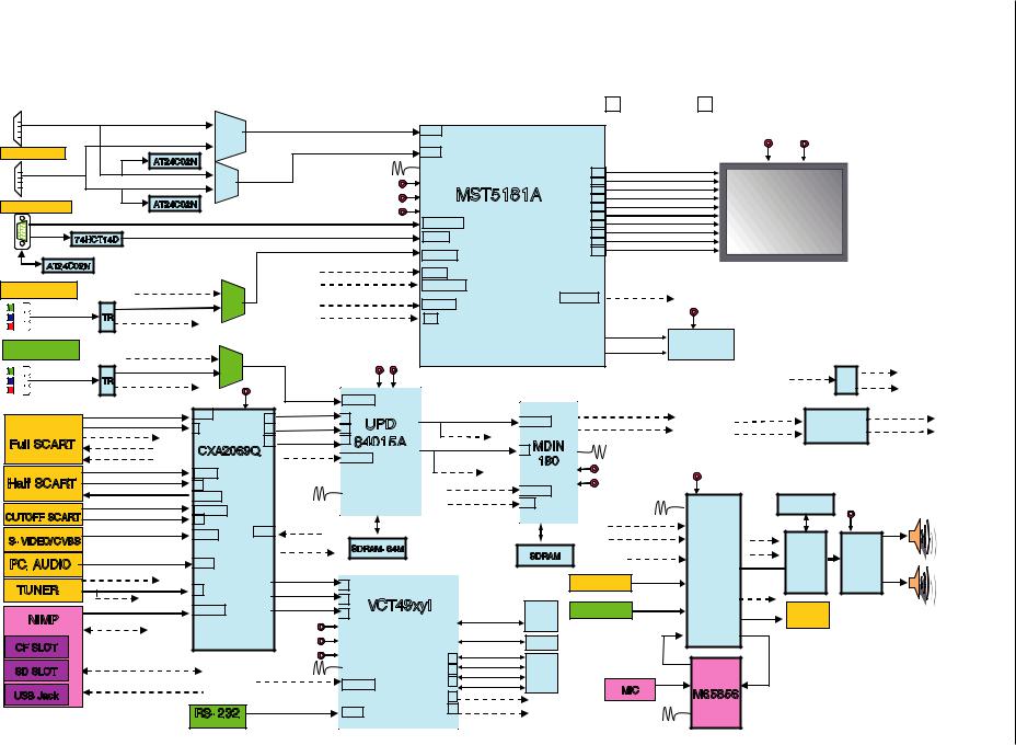
Blockschaltplan / Block Circuit Diagram
|
|
|
|
|
|
|
|
|
HDMI(DVI) |
|
|
Without NIMP |
|
With NIMP |
|
|
Always |
|
|
|
|
|
|
|
|
|
|
|
|
|
|
|
|
PI |
|
|
|
|
|
|
3~13 |
|
|
|
|
|
|
|
|
|
|
|
|
|
|
|
|
|
|
HDMI |
|
|
|
|
|
|
|
|
|
|
|
|
24V |
5V |
|
|
|
|
|
|
|
|
|
|
|
|
|
|
|
|
|
|
|
|
|
|
|
|
|
|
|
|||
|
HDMI(DVI) |
|
|
|
|
|
412 |
|
|
|
|
|
|
18.19 |
|
|
|
|
|
|
|
|
|
|
|
|
|
|
|
AT24C02N |
|
|
|
|
|
|
|
|
|
|
|
|
|
|
|
|
|
|
|||
|
HDMI_Rx |
|
|
|
|
|
|
14.318MHz |
|
|
|
|
|
REX3+ |
|
|
|
|
|
|
|||||
|
|
|
|
|
|
PI3V |
|
|
|
|
|
200 |
|
|
|
|
|
|
|
||||||
|
|
|
|
|
|
|
|
|
|
|
|
3.3V |
|
|
|
|
REX3- |
|
|
|
|
|
|
||
|
|
|
|
|
|
|
|
|
|
|
|
|
|
|
201 |
|
|
|
|
|
|
|
|||
|
|
|
|
|
|
|
512 |
|
|
|
|
|
MST5181A |
|
REXC+ |
|
|
|
|
|
|
||||
|
|
|
|
|
|
|
|
|
|
|
|
2.5V |
204 |
|
|
|
|
|
|
|
|||||
|
|
|
|
|
|
|
|
|
|
|
|
|
205 |
|
REXC- |
|
|
|
|
|
|
||||
|
|
|
|
|
|
|
|
|
|
|
|
|
|
|
|
|
|
|
|
|
|
|
|
|
|
|
RGB_PC/DTV |
|
|
|
AT24C02N |
|
|
|
|
|
|
1.8V |
|
|
|
206 |
|
REX2+ |
|
PANEL |
|
|
|
||
|
|
|
|
|
|
|
|
|
|
|
|
|
|
|
207 |
|
REX2- |
|
|
|
|
||||
|
PC-R/G/B |
|
|
|
|
|
|
|
|
|
24,27,29 |
|
|
|
REX1+ |
|
|
|
|
|
|
||||
|
|
|
|
|
|
|
|
|
|
|
|
208 |
|
|
|
|
|
|
|
||||||
|
PC-H/V |
|
|
|
|
|
|
|
|
|
|
|
|
|
|
|
REX1- |
|
|
|
|
|
|
||
|
|
|
|
|
|
|
|
|
|
|
|
|
22,23 |
|
|
209 |
|
|
|
|
|
|
|
||
|
74HCT14D |
|
|
|
|
|
|
|
|
|
|
|
|
REX0+ |
|
|
|
|
|
|
|||||
|
|
|
|
|
|
|
|
|
|
|
|
|
210 |
|
|
|
|
|
|
|
|||||
|
|
|
|
|
|
|
|
|
|
|
|
|
|
|
|
|
211 |
|
REX0- |
|
|
|
|
|
|
|
|
|
|
|
|
|
|
|
|
|
|
|
|
32,,35,37 |
|
|
|
|
|
|
|
|
|
|
|
|
|
|
|
|
|
|
|
|
|
|
|
|
|
|
|
|
|
|
|
|
|
|
|
|
|
|
I2C AT24C02N |
|
|
|
|
|
MDIN |
MDIN_R/G/B[0..7] |
48~76 |
|
|
|
|
|
|
|
|
|
|
|
|||||
|
|
|
|
|
COMP2-Y1/Pb1/Pr1 |
|
|
|
|
|
|
66,67,68,95 |
|
|
|
|
|
|
|
|
|
|
|||
|
Component 1 |
|
|
|
|
|
|
|
|
|
|
189,190,191 I2S-MST |
|
|
|
|
|
|
|
||||||
|
|
|
|
|
|
PI3V |
|
|
YV[0..7] |
|
|
|
|
|
|
|
|
|
|
||||||
|
|
|
|
|
COMP1-Y1/Pb1/Pr1 |
|
|
|
234~244 |
|
|
|
|
|
|
|
|
||||||||
|
Y1/Pb1/Pr1 |
|
512 |
|
|
|
|
|
|
|
|
|
|
|
|
|
|
||||||||
|
TR |
COMP1-Y2/Pb2/Pr2 |
|
|
|
DECCLK |
|
251 |
|
|
|
|
|
2.5V |
|
|
|
|
|
||||||
|
|
|
|
|
|
|
|
|
|
|
|
|
|
|
|
|
|
|
|
|
|||||
|
|
|
|
|
|
|
|
|
|
|
|
|
|
|
|
|
MDATA[0..31] |
|
|
|
|
|
|
||
|
Component 2 |
|
|
|
COMP1 Y2/Pb2/Pr2 |
|
|
|
|
|
|
|
|
|
|
AR[0..11] |
DDR SDRAM |
|
|
|
|
|
|||
|
|
|
|
PI3V |
|
|
|
|
|
|
|
|
|
|
|
|
|
|
|
|
|
|
|||
- 2 |
|
|
|
COMP2-Y2/Pb2/Pr2 |
|
|
|
|
|
|
|
|
|
|
|
|
|
|
|
|
SC-L/R |
||||
Y2/Pb2/Pr2 |
|
512 |
|
|
|
|
3.3V |
2.5V |
|
|
|
|
|
|
|
|
SU-L/R |
TR |
|||||||
|
|
TR |
|
|
|
|
|
|
|
|
|
|
|
|
|
|
|
|
UX-L/R |
||||||
|
|
|
|
|
|
|
|
|
|
|
|
|
|
|
|
|
|
|
|||||||
|
|
|
|
|
|
|
9V |
|
V OUT-M |
|
41.43.47 |
|
ITU-R 656[YT,7 …0] |
|
MDIN_R/G/B[0..7] |
|
|
|
|
|
|
||||
|
|
|
V1,L1/R1 |
|
1,2,4 |
|
|
|
|
|
|
|
|
|
|
|
|
SCL-A |
|||||||
|
|
|
|
|
53 |
|
59 |
|
|
TW_Y[0..7] |
|
|
CNTL-SCL |
|
|
|
|||||||||
|
|
|
SCART ID1 |
V1,L1/R1 |
Y OUT-M |
|
UPD |
INPUT A |
|
|
ELD |
|
BSS83(5V) |
|
|||||||||||
|
|
|
S26 -1 |
|
56 |
|
58 |
|
|
|
|
|
CNTL-SDA |
SDA-A |
|||||||||||
|
|
|
SCART FB/R/G/B |
|
|
UXF-.656 |
|
|
|
|
|||||||||||||||
|
Full SCART |
|
|
|
58 |
C OUT-M |
|
63 |
64015A |
40 MDIN |
|
|
|
|
|
|
|
|
|
||||||
|
|
|
TV-O |
|
CXA2069Q |
|
|
|
|
|
|
|
|
|
|
|
|
||||||||
|
|
|
|
|
SCART_FB |
|
|
|
|
|
|
27MHz |
|
|
|
|
|
|
|
||||||
|
|
|
|
TV-L/R |
|
|
40.44.46 |
|
|
|
180 |
|
|
|
|
|
|
|
|||||||
|
|
|
|
|
|
|
|
|
|
|
|
|
|
3.3V |
|
|
|
|
|
|
|
|
|||
|
|
|
V2,L2/R2 |
V28,9,11L2/R2 |
|
|
|
|
|
|
UXF_CLK |
|
1.8V |
|
|
|
|
|
|
|
|
||||
|
Half SCART |
SCART ID2 |
|
|
|
|
|
|
|
|
|
|
|
9V |
|
|
|
|
|
||||||
|
S2-2 |
|
|
|
|
|
|
|
|
YV[0..7] |
|
|
|
|
|
|
|
|
|||||||
|
|
SCART2-VO/LO/RO |
13 |
|
|
27MHz |
|
|
|
|
|
INPUT B |
|
18.432MHz |
|
|
|
|
|
||||||
|
|
|
|
SCART2-V |
|
|
|
|
|
DECCLK |
|
|
|
|
|
|
|
||||||||
|
|
|
V5,L5/R5 |
43~45 |
|
|
|
|
|
|
|
H16 |
|
|
|
|
SDRAM-16M |
|
|
|
|||||
|
|
|
29,30,31 |
|
|
|
|
|
|
|
|
|
|
|
|
|
|
|
|||||||
|
CUTOFF SCART |
SCART ID3 |
|
|
|
|
|
|
|
|
|
|
|
|
|
|
|
|
|
|
|||||
|
V5,L5/R527 |
|
|
|
|
|
TDQ[0..15] |
|
|
I2S-MST |
|
|
|
|
|
24V |
L-Out |
||||||||
|
|
|
|
|
|
|
TV-L/R |
|
|
|
MDA[0..63] |
|
|
|
|
|
|||||||||
|
|
|
Y/C1,L1/R1 |
S2-3 |
62,64 |
|
|
|
TAD[0..10] |
SIF/AM-AUDIO |
MSP4450K |
SCL-A |
|
|
|
L |
|||||||||
|
S- VIDEO/CVBS |
15~18 |
|
|
|
|
MA[0..12] |
|
|
|
|||||||||||||||
|
|
|
|
YC3,R3/L3 |
|
CXA-R/L |
|
SDRAM- 64M |
|
|
|
|
|
SDA-A |
|
|
|
|
|||||||
|
|
|
PC_AUDIO_L/R |
|
|
|
|
SDRAM |
|
CXA-R/L |
|
|
AMP |
|
|||||||||||
|
PC_AUDIO |
|
23,25 |
|
|
|
|
|
|
|
|
|
|
SC4 |
I2S/PWM NSP2100 |
|
|||||||||
|
|
|
|
|
|
|
|
|
|
|
|
|
|
|
|
|
|
NSP5112 R-Out |
|||||||
|
|
|
|
|
|
TV-V |
|
|
|
|
|
|
|
|
|
|
|
COMP1-L/R |
|
|
|
|
|
|
|
|
TUNER |
|
TV-V |
|
63 |
|
|
|
|
61 |
|
|
|
|
|
Comp1_L/R |
SC2 |
|
|
|
|
R |
|||
|
|
|
|
|
|
|
|
|
|
|
|
|
|
|
|
|
TV-L/R |
|
|
|
|
||||
|
|
|
|
|
TV-O |
L6/R6 |
|
|
|
64 |
VCT49xyI |
|
|
|
|
|
|
|
|
|
|
||||
|
|
|
|
|
|
|
|
|
|
|
|
|
COMP2-L/R |
|
|
|
|
|
|
||||||
|
NIMP |
|
NIMP_VO/LO/RO |
61,60,59 |
|
|
|
65 |
|
SRAM |
Comp2_L/R |
SC3 |
|
Optical |
|
|
|
||||||||
|
|
|
NIMP-.656 |
|
|
|
5V |
|
|
|
|
|
ADB[0..19] |
8Mbit |
|
|
|
SPDIF-OUT SPDIF |
Out |
|
|
|
|||
|
|
|
|
|
|
|
|
|
|
|
|
|
|
|
|
SC1 |
|
|
|
|
|||||
|
|
|
|
|
|
|
|
|
3.3V |
|
|
|
|
|
ADB[0..19] |
Flash |
|
|
|
|
|
|
|
|
|
|
CF SLOT |
|
|
|
|
|
|
|
|
|
|
|
|
|
|
|
|
|
|
|
|
|
|||
|
|
|
|
|
|
|
|
|
|
|
|
|
|
|
|
|
|
|
|
|
|
|
|||
|
|
|
|
|
|
|
|
1.8V |
|
|
|
|
|
AD_Key2 |
|
|
|
|
|
|
|
|
|
|
|
|
|
|
|
|
|
|
|
|
|
|
|
|
46 |
|
|
|
|
|
|
|
|
|
|
||
|
|
|
|
UXF-CLK,TW_H/V//DE/FIELD |
|
|
20.25MHz |
|
|
|
|
AD_Key1 |
|
|
|
|
|
|
|
|
|
|
|||
|
SD SLOT |
|
|
|
|
|
|
|
|
45 |
|
|
|
|
|
|
|
|
|
|
|||||
|
|
|
|
|
|
|
|
|
TX_INT |
Key |
|
|
|
|
|
|
|
|
|
||||||
|
|
|
|
|
|
|
|
|
|
|
|
|
44 |
|
|
|
|
|
|
|
|
|
|||
|
|
|
|
NIMP_AUDIO_-L/R |
|
SCAR |
|
|
|
67.68.69 |
|
LED_R/G |
|
MIC |
|
M65856 |
|
|
|
|
|
||||
|
USB Jack |
|
|
|
|
|
|
|
|
|
39 YV[0..7] |
|
|
|
|
|
|
|
|||||||
|
|
|
|
|
|
|
|
|
|
|
|
|
|
|
|
|
|
|
|
||||||
|
|
|
|
|
|
RS- 232 |
UART_RX/TX |
|
81,82 |
|
40 |
DECCLK |
|
|
2MHz |
|
|
|
|
|
|
|
|||
|
|
|
|
|
|
|
|
|
|
|
|
|
|
|
|
|
|
|
|
|
|||||
Service GRUNDIG
P060L46M4W2 Chassis
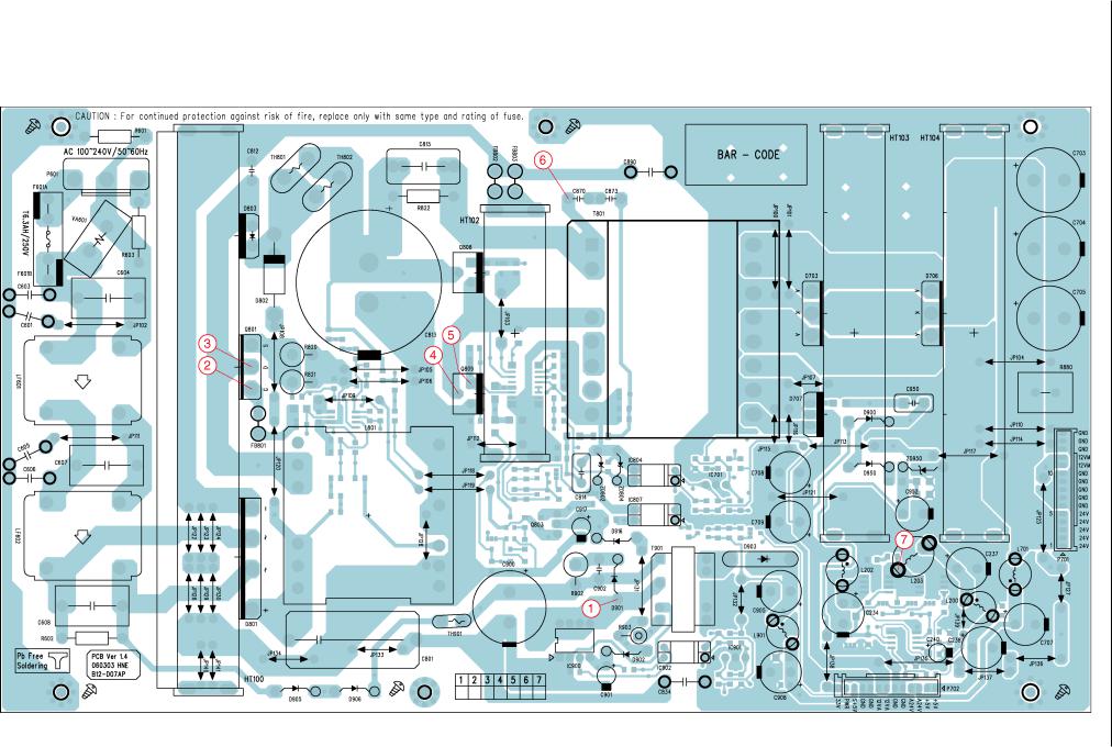
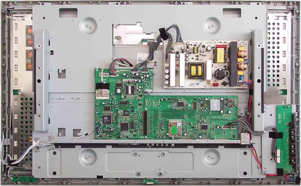
Netzteil-Platte / Power Supply Board 40“
Ansicht von der Bestückungsseite / View of Component Side
- 2
Service GRUNDIG
P060L46M4W2 Chassis
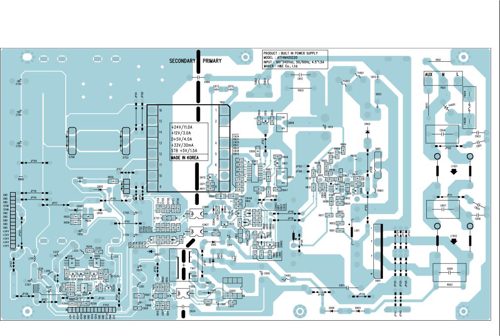
Netzteil-Platte / Power Supply Board 40“
Ansicht von der Lötseite / View of Solder Side
- 2
Service GRUNDIG
P060L46M4W2 Chassis

Netzteil-Platte / Power Supply Board 40“
1 |
2 |
-2 |
3 |
4 |
5 |
6 |
|
3 |
2 |
6 |
|
|
4 |
4 |
5 |
|
1 |
|
to P. 2-22 GRUNDIG P804
Service
to P. 2-22 P803
7
|
Chassis |
7 |
P060L46M4W2 |
IC Block Diagrams, see P. 2-8 |
|
 Loading...