


|
|
|
|
|
TV |
|
Service Manual |
||
Chassis E4
Davio 21
|
|
|
|
|
|
|
|
|
|
|
|
|
|
|
|
|
|
|
|
|
|
|
|
|
T 55-4501 Text |
GBE1900 |
|
|
|
|
|
|
|
|
|
|
|
|
|
|
|
|
|
|
|
|
|
|
|
|
|
T 55-4501/5 Text |
GBE2200 |
|
|
|
|
|
|
|
|
|
|
|
|
|
|
|
|
|
|
|
|
|
|
|
|
|
|
|
|
|
|
|
|
|
|
|
|
|
|
|
|
|
|
|
|
|
|
|
|
|
|
|
|
|
|
Davio 20
|
T 51-4501 Text |
GBE2000 |
|
|
|
|
|
|
Zusätzlich erforderliche Unterlagen für den Komplettservice
Additionally required Service Documents for the Complete Service
Service
Manual
Sicherheit
Safety
Materialnr./Part No.
720108000001
Materialnummer / Part Number 720100528000 Änderungen vorbehalten / Subject to alteration TCC 0507 HH • Prepared in Germany http://www.grundig.com

GRUNDIG Service |
Chassis E4 |
|
|
Es gelten die Vorschriften und Sicherheitshinweise gemäß dem Service Manual "Sicherheit", Materialnummer 720108000001, sowie zusätzlich die eventuell abweichenden, landesspezifischen Vorschriften!
The regulations and safety instructions shall be valid as provided by the "Safety" Service Manual, part number 720108000001, as well as the respective national deviations.
Inhaltsverzeichnis
|
Seite |
Allgemeiner Teil..................................... |
1-2…1-9 |
Chassisvarianten............................................................................ |
1-2 |
Allgemeine Hinweise...................................................................... |
1-2 |
Sicherheitshinweise....................................................................... |
1-3 |
Technische Daten.......................................................................... |
1-3 |
Bedienhinweise.............................................................................. |
1-6 |
Serviceund Sonderfunktionen...................................................... |
1-8 |
Abgleich.......................................................... |
2-1 |
Platinenabbildungen |
|
und Schaltpläne.................................. |
3-1…3-16 |
Chassis X1X.190-01: |
|
– Netzteil....................................................................................... |
3-1 |
– Horizontal-Ablenkung................................................................. |
3-2 |
– Vertikal-Ablenkung..................................................................... |
3-3 |
– Hauptteil..................................................................................... |
3-4 |
– Schalter Front AV....................................................................... |
3-7 |
– Leiterplatte X1X.190-01.............................................................. |
3-8 |
– Bildrohrplatte............................................................................ |
3-15 |
Variantenliste............................................................................... |
3-16 |
Ersatzteillisten....................................... |
4-1…4-5 |
Table of Contents
|
Page |
General Section..................................... |
1-2…1-9 |
Chassis Variants............................................................................ |
1-2 |
General Notes................................................................................ |
1-2 |
Safety Advices............................................................................... |
1-3 |
Technical Data............................................................................... |
1-3 |
Operating Hints.............................................................................. |
1-7 |
Service and Special Functions....................................................... |
1-8 |
Adjustment..................................................... |
2-1 |
Layout of the PCBs |
|
and Circuit Diagrams.......................... |
3-1…3-16 |
Chassis X1X.190-01: |
|
– Power Supply............................................................................. |
3-1 |
– Horizontal Deflection ................................................................. |
3-2 |
– Vertical Deflection...................................................................... |
3-3 |
– Main Part.................................................................................... |
3-4 |
– Front AV Switch.......................................................................... |
3-7 |
– PCB X1X.190-01........................................................................ |
3-8 |
– CRT Board............................................................................... |
3-15 |
Variant List................................................................................... |
3-16 |
Spare Parts Lists................................... |
4-1…4-5 |
Allgemeiner Teil
Chassisvarianten
Einige Gerätetypen wurden sowohl mit Chassis E4 als auch mit
Chassis E1 produziert.
Für Chassis E1 sind das Service Manual Chassis E1 (720100512000) sowie die Ergänzungen 1 bis 4 (-2100, -2200, -2300, -2400) maßgebend.
Auf dem Typenschild (Geräterückseite) ist die Chassisbezeichnung aufgedruckt.
Allgemeine Hinweise
Vor dem Öffnen des Gehäuses den Netzstecker ziehen! Achtung: ESD-Vorschriften beachten 
Leitungsverlegung
Bevor Sie die Leitungen und insbesondere die Masseleitungen lösen, muss die Leitungsverlegung zu den einzelnen Baugruppen beachtet werden.
Nach erfolgter Reparatur ist es notwendig, die Leitungsführung wieder in den werkseitigen Zustand zu versetzen um evtl. spätere Ausfälle oder Störungen zu vermeiden.
Durchführen von Messungen
Bei Messungen mit dem Oszilloskop an Halbleitern sollten Sie nur Tast köpfe mit 10:1 - Teiler verwenden. Außerdem ist zu beachten, dass nach vorheriger Messung mit AC-Kopplung der Koppelkondensator des Oszilloskops aufgeladen sein kann. Durch die Entladung über das Messobjekt können Bauteile beschädigt werden.
Messwerte und Oszillogramme
Bei den in den Schaltplänen und Oszillogrammen angegebenen
Messwerten handelt es sich um Näherungswerte!
General Section
Chassis Variants
Some types of sets are produced with chassis E4 as well as with
Chassis E1.
For chassis E1 Service Manual Chassis E1 (720100512000) as well as supplements 1 to 4 (-2100, -2200, -2300, -2400) are standard.
Type of chassis is printed on the type label (rear side).
General Notes
Before opening the cabinet disconnect the mains plug! Attention: Observe the ESD safety regulations 
Wiring
Before disconnecting any leads and especially the earth connecting leads observe the way they are routed to the individual assemblies. On completion of the repairs the leads must be laid out as originally fitted at the factory to avoid later failures or disturbances.
Carrying out Measurements
When making measurements on semi-conductors with an oscilloscope, ensure that the test probe is set to 10:1 dividing factor. If the previous measurement was made on AC input, please note that the coupling capacitor in the oscilloscope will be charged. Discharge via the item being checked can damage the components.
Measured Values and Oscillograms
The measured values given in the circuit diagrams and oscillograms are approximates!
1 -
GRUNDIG Service |
Chassis E4 |
Sicherheits-Hinweise
Die in den Fernsehgeräten auftretende Röntgenstrahlung entspricht den Bestimmungen der Physikalisch-Technischen Bundesanstalt vom 8. Januar 1987.
Die Hochspannung für die Bildröhre und die damit auftretende Röntgenstrahlung ist abhängig von der exakten Einstellung der Netz-teilspannung +B.
Nach jeder Reparatur im Netzteil oder in der Horizontalablenkung ist die Hochspannung zu messen und gegebenenfalls einzustellen. Schutzschaltungen im Gerät dürfen nur kurzzeitig außer Betrieb gesetzt werden, um Folgeschäden am Chassis oder an der Bildröhre zu vermeiden.
Beim Austausch der Bildröhre dürfen nur die in den Ersatzteillisten vorgeschriebenen Typen verwendet werden.
Netzkabel
Diese Geräte dürfen nur mit dem Original-Netzanschlusskabel mit integrierter Entstördrossel betrieben werden. Dieses Netzkabel verhindert Störungen aus dem Netz und ist Bestandteil der Gerätezulassung. Im Ersatzfall bestellen Sie bitte ausschließlich das Netzkabel laut Ersatzteilliste.
Safety Advices
The X-radiation developing in the sets conforms to the X-radiation Regulations (January 8, 1987), issued by the Physikalisch-Techni- sche Bundesanstalt (federal physiotechnical institution).
The high tension for the picture tube and thus the developing X-ra- diation depends on the precise adjustment of the +B power supply. After every repair of the power supply unit or the horizontal deflection stage it is imperative that the EHT for the picture tube is checked and re-adjusted if necessary.
To avoid consequential damages to the chassis or the picture tube the integrated protective circuits are allowed to be put out of operation only for a short time.
When replacing the picture tube use only the types specified in the spare parts lists.
Mains cable
The TV receiver must only be operated with an original mains connecting cable with an interference suppressor choke integrated in the mains plug. This mains cable prevents interference from the mains supply and is part of the product approval. For replacement please order exclusively the mains connecting cable specified in the spare parts list.
Technische Daten / Technical Data
|
Davio 21 |
|
|
Davio 21 |
Davio 20 |
|
|
T55-4501 Text |
|
|
T55-4501/5 Text |
T51-4501 Text |
|
|
CQF |
|
|
CQG |
CPM |
|
|
|
|
|
|
|
|
Order Number |
GBE1900 |
|
|
GBE2200 |
GBE2000 |
|
|
40 13833-60216 3 |
|
|
40 13833-60219 4 |
40 13833-60217 0 |
|
EAN |
|
|
|
|||
|
|
procon silber |
|
|
|
|
Colour |
|
|
procon silber |
|
||
|
|
|
|
|
||
Destination |
D,A,I,E,P,B,CH,NL,DK, |
|
CZ,H,HR,SI |
D,A,I,E,P,B,CH,NL,DK, |
|
|
FIN,N,S,TR |
|
|
FIN,N,S,TR |
|
||
|
|
|
|
|
||
|
D,GB,F,I,NL,DK, |
|
|
|
D,GB,F,I,NL,DK, |
|
User manual languages |
|
|
CZ,H,SI |
|
||
N,S,FIN,E,P |
|
|
N,S,FIN,E,P |
|
||
|
|
|
|
|
||
|
|
|
|
|
|
|
Remote Control |
|
TP 160 C |
|
TP 160 C |
|
|
|
|
|
|
|
|
|
PICTURE |
|
|
|
|
|
|
Size / Type |
55cm (21"), FST, (4:3) |
51cm (20"), FST, (4:3) |
|
|||
|
|
|
|
|
|
|
Real flat / Super flat |
|
\ / \ |
|
\ / \ |
|
|
|
|
|
|
|
|
|
Deflection |
|
90° |
|
90° |
|
|
|
|
|
|
|
|
|
100 Hz Picture-/32 kHz line frequency |
|
\ |
|
\ |
|
|
|
|
|
|
|
|
|
Flicker free scanning (full frame memory) |
|
\ |
|
\ |
|
|
|
|
|
|
|
|
|
Digital Color Transition Improv. (DCTI) |
|
\ |
|
\ |
|
|
|
|
|
|
|
|
|
Digital Combfilter |
|
\ |
|
\ |
|
|
|
|
|
|
|
|
|
Digital Luminance Transition Improv.(DLTI) |
|
\ |
|
\ |
|
|
|
|
|
|
|
|
|
Picture Noise Reduction |
|
\ |
|
\ |
|
|
|
|
|
|
|
|
|
SVM (Scan Velocity Modulation) |
|
\ |
|
\ |
|
|
|
|
|
|
|
|
|
Dynamic Focus |
|
\ |
|
\ |
|
|
|
|
|
|
|
|
|
Preset picture modes |
|
\ |
|
\ |
|
|
|
|
|
|
|
|
|
Tilt |
|
\ |
|
\ |
|
|
|
|
|
|
|
|
|
Picture Formats |
|
4:3 / 16:9 |
|
4:3 / 16:9 |
|
|
|
|
|
|
|
|
|
PIP (2 Tuner) |
|
\ |
|
\ |
|
|
|
|
|
|
|
|
|
Multifold Tuner scan (Mosaic Picture) |
|
\ |
|
\ |
|
|
|
|
|
|
|
|
|
PAT: Split screen (PICTURE + TEXT) |
|
\ |
|
\ |
|
|
|
|
|
|
|
|
|
PAP: Double Window (PICTURE + PICTURE) |
|
\ |
|
\ |
|
|
|
|
|
|
|
|
|
P2AT: Double Window + TXT |
|
\ |
|
\ |
|
|
|
|
|
|
|
|
|
POP: PICTURE on PICTURE |
|
\ |
|
\ |
|
|
|
|
|
|
|
|
|
Picture freezing |
|
\ |
|
\ |
|
|
|
|
|
|
|||
Quick programme display |
[(with OK button) |
[(with OK button) |
|
|||
|
|
|
|
|
|
|
Zoom with point function |
|
\ |
|
\ |
|
|
|
|
|
|
|
|
|
Auto 16:9 selection via Scart |
|
[ |
|
[ |
|
|
|
|
|
|
|
|
|
1 - 3

GRUNDIG Service Chassis E4
|
Davio 21 |
|
Davio 21 |
Davio 20 |
|
|
T55-4501 Text |
|
T55-4501/5 Text |
T51-4501 Text |
|
|
CQF |
|
CQG |
CPM |
|
Automatic Color Standard Detection |
|
|
|
|
|
|
\ |
\ |
|
||
|
|
|
|
|
|
Sharpness control |
|
[ |
[ |
|
|
|
|
|
|
|
|
Blue Background |
|
[ |
[ |
|
|
|
|
|
|
|
|
CHASSIS |
|
|
|
|
|
TV-Chassis |
|
E 4 (50 Hz) |
E 4 (50 Hz) |
|
|
|
PLL frequency synthesizer tuning |
PLL frequency synthesizer |
|
||
Tuner |
|
||||
tuning |
|
||||
|
|
|
|
|
|
|
|
UOC |
|
|
|
µ-Processor |
|
UOC |
|
||
|
|
|
|
3 ± keys for programme |
|
Keyboard |
3 ± keys for programme selection and volume |
|
|||
selection and volume |
|
||||
|
|
|
|
|
|
|
|
|
|
|
|
ELECTRONIC |
|
|
|
|
|
Stand by indicator |
|
red LED |
red LED |
|
|
|
|
|
|
|
|
Manual & autom. labeling of prog. |
|
5 characters |
5 characters |
|
|
|
|
|
|
|
|
Programmable off timer |
|
[ |
[ |
|
|
|
|
|
|
|
|
Programmable on timer |
|
\ |
\ |
|
|
|
|
|
|
|
|
Intelligent channel search (Zapping funct.) |
|
[ |
[ |
|
|
|
|
|
|
|
|
Programme Edit |
|
[ |
[ |
|
|
|
|
|
|
|
|
Intelligent Programme Switch |
|
\ |
\ |
|
|
|
|
|
|
|
|
Auto switch off |
|
[ |
[ |
|
|
|
|
|
|
|
|
Programme memory TV/AV (opt.) |
|
100/AV |
100/AV |
|
|
|
|
|
|
|
|
Teletext/Fasttext/Toptext |
|
1 page / 1 page / \ |
1 page / 1 page / \ |
|
|
|
|
|
|
|
|
Teletext options |
|
\ |
\ |
|
|
|
|
|
|
|
|
Teletext SWAP |
|
\ |
\ |
|
|
|
|
|
|
|
|
Childlock |
|
[ |
[ |
|
|
|
|
26 Languages: |
26 Languages: |
|
|
|
|
|
|||
Menue languages OSD (Version A) |
D,GB,F,I,E,P,NL,GR,TR, |
D,GB,F,I,E,P,NL,GR,TR,DK,FI |
|
||
DK,FIN,N,S,SI,PL,H,Cyr, |
N,N,S,SI,PL,H,Cy,RO,HR,CZ, |
|
|||
|
|
||||
|
RO,HR,CZ,SK,AL,BG,MK,SER,HEB |
SK,AL,BG,MK,SER,HEB |
|
||
|
|
|
|
|
|
SWAP (Recall function) |
|
\ |
\ |
|
|
|
|
|
|
|
|
Service mode |
|
[ |
[ |
|
|
|
|
|
|
|
|
Luxury packet |
|
\ |
\ |
|
|
|
|
|
|
|
|
Hotel mode |
|
[ |
[ |
|
|
|
|
|
|
|
|
TUNING |
|
|
|
|
|
Autom. Tuning System with country selection |
|
[ |
[ |
|
|
|
|
|
|
|
|
Frequency Based Auto Search |
|
[ |
[ |
|
|
|
|
|
|
|
|
Automatic Micro-search |
|
[ |
[ |
|
|
|
|
|
|
|
|
Automatic Programming |
|
\ |
\ |
|
|
|
|
|
|
|
|
Manual fine tuning |
|
[ |
[ |
|
|
|
|
|
|
|
|
Direct channel selection |
|
[ |
[ |
|
|
|
|
|
|
|
|
PAL/SECAM/BG/DK/LL' |
[/\/[/\/\ |
|
[/[/[/[/\ |
[/\/[/\/\ |
|
|
|
|
|
|
|
NTSC-Playback via Scart (3,58/4,43) |
|
[ |
[ |
|
|
|
|
|
|
|
|
Cable TV / Hyperband (S1-S41) |
|
[ |
[ |
|
|
|
|
|
|
|
|
AUDIO |
|
|
|
|
|
Mono/Stereo/Nicam |
|
[ / \ / \ |
[ / \ / \ |
|
|
|
|
|
|
|
|
AV Stereo |
|
\ |
\ |
|
|
|
|
|
|
|
|
Virtual Dolby |
|
\ |
\ |
|
|
|
|
|
|
|
|
Subwoofer |
|
\ |
\ |
|
|
|
|
|
|
|
|
Dynamic Bass |
|
\ |
\ |
|
|
|
|
|
|
|
|
DSP (Digital Sound Processor) |
|
\ |
\ |
|
|
|
|
|
|
|
|
Balance Adjustment |
|
\ |
\ |
|
|
|
|
|
|
|
|
AVL (Audio Volume Level) |
|
[ |
[ |
|
|
|
|
|
|
|
|
1 - 4

GRUNDIG Service Chassis E4
|
Davio 21 |
|
Davio 21 |
Davio 20 |
|
|
T55-4501 Text |
|
T55-4501/5 Text |
T51-4501 Text |
|
|
CQF |
|
CQG |
CPM |
|
PIP listening via Headphone.jack |
|
|
|
|
|
|
\ |
\ |
|
||
|
|
|
|
|
|
Equalizer |
|
\ |
\ |
|
|
|
|
|
|
|
|
Space Sound Effect |
|
\ |
\ |
|
|
|
|
|
|
|
|
Audio mode |
|
\ |
\ |
|
|
|
|
|
|
|
|
Audio amplifier without extern LS |
|
2,5 W (RMS) |
2,5 W (RMS) |
|
|
|
|
|
|
|
|
Tweeter (2 way speaker system) |
|
\ |
\ |
|
|
|
|
|
|
|
|
POWER SUPPLY / CABINET |
|
|
|
|
|
Power voltage |
|
230V~, 50/60 Hz |
230V~, 50/60 Hz |
|
|
|
|
|
|
|
|
Power switch |
|
[ |
[ |
|
|
|
|
41 W, standby 4 W |
41 W, standby 4 W |
|
|
|
|
|
|||
Power consumption |
|
in accordance to |
in accordance to |
|
|
|
|
IEC 62087-2002 |
IEC 62087-2002 |
|
|
|
50,8 x 47,8 x 48,6 cm / |
50,8 x 47,8 x 47,9 cm / |
|
||
Cabinet (WxHxD, cm) / Weight |
|
||||
|
approx. 20,2 kg |
approx. 17,4 kg |
|
||
|
|
|
|||
|
|
|
|
|
|
FRONT PANEL CONNECTIONS |
|
|
|
|
|
Headphones |
|
\ |
\ |
|
|
|
|
|
|
|
|
Cinch-AV socket |
|
\ |
\ |
|
|
|
|
|
|
|
|
S-Video |
|
\ |
\ |
|
|
|
|
|
|
|
|
REAR PANEL CONNECTIONS |
|
|
|
|
|
Euro-AV-Socket AV1 |
CVBS in-/output, RGB input, S-Video input |
CVBS in-/output, RGB input, |
|
||
S-Video input |
|
||||
|
|
|
|
|
|
|
|
|
|
|
|
Euro-AV Socket AV2 |
|
\ |
\ |
|
|
|
|
|
|
|
|
Euro-AV Socket AV3 |
|
\ |
\ |
|
|
|
|
|
|
|
|
S-Video |
|
[ via Scart |
[ via Scart |
|
|
|
|
|
|
|
|
Audio out |
|
\ |
\ |
|
|
|
1 x Coaxial-socket for |
1 x Coaxial-socket for |
|
||
|
|
||||
Antenna for terrestial reception |
|
TV-tuner-in, |
TV-tuner-in, |
|
|
|
according to DIN 45325 |
according to DIN 45325 |
|
||
|
|
|
|
|
|
Power supply plug |
|
\ |
\ |
|
|
|
|
|
|
|
|
|
|
|
|
|
|
1 - 5

Bedienhinweise Dieses Kapitel enthält Auszüge aus der Bedienungsanleitung.
Weitergehende Informationen entnehmen Sie bitte der gerätespezifischen Bedienungsanleitung, deren Materialnummer Sie in der entsprechenden Ersatzteilliste finden.
6 - 1
Service GRUNDIG
E4 Chassis
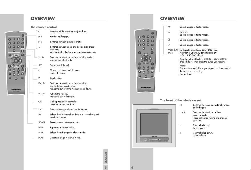
Operating Hints This chapter contains excerpts from the operating instructions.
For further particulars please refer to the appropriate user instructions the part number of which is indicated in the relevant spare parts list.
7 - 1
Service GRUNDIG
E4 Chassis

GRUNDIG Service |
Chassis E4 |
Serviceund Sonderfunktionen
Service Mode aktivieren: Taste "i" –> Service Code "8500".
Menü aufrufen: |
Taste "P+"/"P-" ->"OK". |
Einstellung verändern: |
Taste " / " bzw. 1/3, 4/6. |
Menü verlassen: |
Taste "i". |
Service Mode beenden: |
Taste "TXT". |
1. Grundeinstellwerte
Nachfolgende Tabelle zeigt alle typenbezogenen Grundeinstellungen im Service Mode. Alle mit * gekennzeichneten Werte müssen zusätzlich nach Abgleich (Seite 2-1) eingestellt werden.
Service and Special Functions
Start of the Service Mode: Via "i" –> Service Code "8500".
Call up the Menu: |
Button "P+"/"P-" ->"OK". |
Adjustments: |
Button " / " bzw. 1/3, 4/6. |
Break of the Menu: |
Button "i". |
End the Service Mode: |
Button "TXT". |
1. Basic Settings
The following table shows all type specific basic settings in the service mode. In addition all values marked with * must be adjusted according to adjustment (page 2-1).
|
|
|
|
|
Gerät / Type of Set |
|
||
Menü |
|
Einstellung |
|
|
|
|
|
|
Menüpunkt |
|
21Davio Text4501-T55 |
|
21Davio Text4501/5-T55 |
|
20Davio Text4501-T51 |
||
Menu |
Adjustment |
Hinweis |
|
|
||||
P+/P- |
Point of Menu |
/ |
|
|
|
|
|
|
Hint |
|
|
|
|
|
|||
+ |
P+/P- |
(-10) 1 / 3 (+10) |
|
|
|
|
|
|
|
|
|
|
|
|
|||
"OK" |
|
(-100) 4 / 6 (+100) |
|
|
|
|
|
|
|
|
|
|
|
|
|
|
|
|
|
Temic |
abhängig von |
|
|
|
|
|
|
|
Panasonic D44G3 |
|
|
|
|
|
|
|
|
Bestückung |
|
|
|
|
|
|
|
TUNER |
Sharp or Alps (Samsung) |
depending on |
|
|
|
|
|
|
|
Philips |
|
|
|
|
|
|
|
|
mounting |
|
|
|
|
|
|
|
|
Panasonic DB2G3 |
|
|
|
|
|
|
|
|
|
|
|
|
|
|
|
|
AGC (UHF) |
*Wert/Value |
|
30 |
|
30 |
|
30 |
|
AGC (VHF) |
*Wert/Value |
|
30 |
|
30 |
|
30 |
|
|
|
|
|
|
|
|
|
|
AGC (LPRIME) |
*Wert/Value |
|
20 |
|
20 |
|
20 |
|
TYPE |
ATS |
|
X |
|
X |
|
X |
|
LABEL |
|
|
|
|
|
|
|
|
|
|
|
|
|
|
|
|
|
STANDBY |
CUSTOMER MODE |
|
X |
|
X |
|
X |
|
FACTORY MODE |
|
|
|
|
|
|
|
|
|
|
|
|
|
|
|
|
|
AV1 SVHS |
ON |
|
X |
|
X |
|
X |
|
OFF |
|
|
|
|
|
|
|
|
|
|
|
|
|
|
|
|
|
AV2 |
ON |
|
|
|
|
|
|
|
OFF |
|
X |
|
X |
|
X |
|
|
|
|
|
|
||||
|
|
BG |
|
X |
|
|
|
X |
|
|
|
|
|
|
|
|
|
|
SOUND |
I |
|
|
|
|
|
|
OPTIONS |
BG+DK |
|
|
|
X |
|
|
|
|
|
|
|
|
|
|||
|
BG+LL´ |
|
|
|
|
|
|
|
|
|
|
|
|
|
|
|
|
|
|
EUROPE |
|
X |
|
X |
|
X |
|
BG |
NEW ZELLAND |
|
|
|
|
|
|
|
|
AUSTRALIA |
|
|
|
|
|
|
|
TEXT |
FASTTEXT |
|
X |
|
X |
|
X |
|
|
|
|
|
|
|
|
|
|
NON-TEXT |
|
|
|
|
|
|
|
|
|
|
|
|
|
|
|
|
|
ON TIMER |
ON |
|
|
|
|
|
|
|
OFF |
|
X |
|
X |
|
X |
|
|
|
|
|
|
||||
|
|
INT.PV-+ |
|
|
|
|
|
|
|
|
INT.-PV+ |
|
X |
|
X |
|
X |
|
FRONT KEY |
EXT.PV-+ |
|
|
|
|
|
|
|
|
EXT.-PV+ |
|
|
|
|
|
|
|
|
EXT.4 KEY |
|
|
|
|
|
|
|
BLUEBACK |
ON |
|
X |
|
X |
|
X |
|
OFF |
|
|
|
|
|
|
|
|
|
|
|
|
|
|
|
|
|
AUTO WSS |
ON |
|
X |
|
X |
|
X |
|
OFF |
|
|
|
|
|
|
|
|
|
|
|
|
|
|
|
|
|
CHILD LOCK |
ON |
|
X |
|
X |
|
X |
|
OFF |
|
|
|
|
|
|
|
|
|
|
|
|
|
|
|
|
|
ZAPP |
ON |
|
X |
|
X |
|
X |
|
OFF |
|
|
|
|
|
|
|
|
|
|
|
|
|
|
|
|
|
RC TYPE |
TP751C |
je nach Fernbedienung |
|
|
|
|
|
OPTIONS |
TP160C |
depending on RC |
X |
|
X |
|
X |
|
|
|
|
||||||
|
|
|
|
|
|
|
|
|
SIMPLE HOTEL |
ON |
|
|
|
|
|
|
|
|
OFF |
|
X |
|
X |
|
X |
|
|
|
|
|
|
||||
|
MAX VOLUME |
Wert/Value |
max. volume in hotel mode |
32 |
|
32 |
|
32 |
|
RGB IN |
ON |
|
X |
|
X |
|
X |
|
OFF |
|
|
|
|
|
|
|
|
|
|
|
|
|
|
|
|
1 - 8

GRUNDIG Service Chassis E4
|
|
|
|
|
|
Gerät / Type of Set |
|
|
||
Menü |
|
Einstellung |
|
|
|
|
|
|
|
|
Menüpunkt |
|
21Davio Text4501-T55 |
|
21Davio Text4501/5-T55 |
|
20Davio Text4501-T51 |
|
|||
Menu |
Adjustment |
Hinweis |
|
|
|
|||||
P+/P- |
Point of Menu |
/ |
|
|
|
|
|
|
||
Hint |
|
|
|
|
|
|
||||
+ |
P+/P- |
(-10) 1 / 3 |
(+10) |
|
|
|
|
|
|
|
|
|
|
|
|
|
|
||||
"OK" |
|
(-100) 4 / 6 |
(+100) |
|
|
|
|
|
|
|
|
|
|
|
|
|
|
|
|
|
|
|
VER. AMPLITUDE |
*Wert/Value |
|
|
03 |
|
03 |
|
03 |
|
|
|
|
|
|
|
|
|
|
|
|
|
VER. SHIFT |
*Wert/Value |
|
|
33 |
|
33 |
|
33 |
|
|
VER. SLOPE |
*Wert/Value |
|
|
32 |
|
32 |
|
32 |
|
|
|
|
|
|
|
|
|
|
|
|
|
S-CORRECTION |
*Wert/Value |
|
|
30 |
|
30 |
|
30 |
|
|
HOR. SHIFT |
*Wert/Value |
|
|
34 |
|
34 |
|
34 |
|
|
VER. AMP. 16:9 |
*Wert/Value |
|
|
12 |
|
12 |
|
12 |
|
GEOMETRY |
YC DELAY PAL |
Wert/Value |
|
nicht ändern/do not change |
07 |
|
07 |
|
07 |
|
YC DELAY SECAM |
Wert/Value |
|
nicht ändern/do not change |
07 |
|
07 |
|
07 |
|
|
|
YC DELAY NTSC |
Wert/Value |
|
nicht ändern/do not change |
07 |
|
07 |
|
07 |
|
|
|
|
|
|
|
|
|
|
|
|
|
HOR. OSD POS. |
*Wert/Value |
|
|
37 |
|
37 |
|
37 |
|
|
VER. OSD POS. |
*Wert/Value |
|
|
04 |
|
04 |
|
04 |
|
|
OSD CON. |
*Wert/Value |
|
|
06 |
|
06 |
|
06 |
|
|
TXT CON. |
*Wert/Value |
|
|
00 |
|
00 |
|
00 |
|
|
TXT BRI. |
Wert/Value |
|
nicht ändern/do not change |
30 |
|
30 |
|
30 |
|
|
PWL |
Wert/Value |
|
nicht ändern/do not change |
08 |
|
08 |
|
08 |
|
|
CATH. DRV. LEV. |
Wert/Value |
|
nicht ändern/do not change |
10 |
|
10 |
|
10 |
|
|
VERTICAL GUARD |
Wert/Value |
|
nicht ändern/do not change |
00 |
|
00 |
|
00 |
|
|
|
|
|
|
|
|
|
|
|
|
|
PROTECTION |
Wert/Value |
|
nicht ändern/do not change |
04 |
|
04 |
|
04 |
|
|
BLACK LEVEL R |
Wert/Value |
|
nicht ändern/do not change |
19 |
|
19 |
|
19 |
|
VIDEO |
BLACK LEVEL G |
*Wert/Value |
|
|
27 |
|
27 |
|
27 |
|
WHITE POINT R |
*Wert/Value |
|
|
32 |
|
32 |
|
32 |
|
|
|
|
|
|
|
|
|||||
|
WHITE POINT G |
*Wert/Value |
|
|
32 |
|
32 |
|
32 |
|
|
WHITE POINT B |
*Wert/Value |
|
|
32 |
|
32 |
|
32 |
|
|
SCREEN ADJ. |
*Wert/Value |
|
|
00 |
|
00 |
|
00 |
|
-EE PROM EDIT |
ADDRESS |
|
|
Achtung! nur für Fertigung |
|
|
|
|
|
|
|
DATA (HEX) |
|
|
Attention! Only for produc- |
|
|
|
|
|
|
|
|
|
|
tion |
|
|
|
|
|
|
|
DATA (BINARY) |
|
|
|
|
|
|
|
|
|
|
|
|
|
|
|
|
|
|
|
|
|
|
|
|
|
|
|
|
|
|
|
|
|
|
|
|
|
|
|
|
|
|
ATS Reset
"–"-Taste (Minus) am Gerät gedrückt halten und mit der Fernbedienung auf Standby schalten. -> Beim nächsten Einschalten erscheint das Menü "Sprache".
Austausch des IC101 oder IC103
Nach Austausch des IC101 oder IC103 müssen alle Einstellungen im Service Mode nach Tabelle "Grundeinstellwerte" (Punkt 1) überprüft und gegebenenfalls durchgeführt werden.
Software-Versionsnummer
Die TV-Software-Versionsnummer wird im Service Menü angezeigt: z.B. SE1.641G-A04
14/12/04
09:33:14
Hotel-Mode
Bei aktivierter Funktion ist die maximale Lautstärke begrenzt und die Programmtabelle und Installation sind im MENU INFO nicht mehr enthalten.
Aufruf: " i " –> "8500" –> P+ / P– "OPTIONS" –> "OK" –> P+ / P– "SIMPLE HOTEL" –> / "ON".
Maximale Lautstärke: " i " –> "8500" –> P+ / P– "OPTIONS" –> "OK"
–> P+ / P– "MAX VOL" –> / Wert 0…63.
ATS Reset
Hold "–" button (minus) on the TV set depressed while switching the set to standby with the remote control. -> Menu "Language" appears at the next "switch on".
Change of the IC101 or IC103
After changing the IC101 or IC103 all settings in the service mode must be checked and if necessary be done according to the table
"Basic Settings" (point 1).
Software Version Number
The TV software version number is shown in the Service Menu: e.g. SE1.641G-A04
14/12/04
09:33:14
Hotel Mode
Maximum volume is limited and there is no access to "Preset List" and "Channel Settings" at activated hotel mode.
Call up: " i " –> "8500" –> P+ / P– "OPTIONS" –> "OK" –> P+ / P– "SIMPLE HOTEL" –> / "ON".
Maximum volume: " i " –> "8500" –> P+ / P– "OPTIONS" –> "OK" –>
P+ / P– "MAX VOL" –> / Value 0…63.
1 - 9
GRUNDIG Service |
Chassis E4 |
Abgleich
Messgeräte: Digitalvoltmeter, Farbbildgenerator.
Servicearbeiten nach Austausch bzw. Reparatur:
–Netzteil: Abgleich 1, 3
–Tuner / ZF: Abgleich 2
–IC103 (EEPROM): Abgleich 2, 4, 5
–Bildröhre: Abgleich 3, 5
–Bildrohrplatte: Abgleich 3, 5
–Ablenkung: Abgleich 4
1.Spannung B+
–Digitalvoltmeter: D609 Kathode
–Programm: AV
–Helligkeit auf Minimum
–Spannung B+ mit P601 entsprechend der Bildröhre einstellen (siehe Variantenliste Seite 3-16).
2.AGC
–Service Mode aufrufen: Taste " i " drücken –> "8500" eingeben.
–Service Menü OPTIONS mit den Tasten P+ / P- anwählen und mit OK aufrufen.
–AGC (UHF) mit den Tasten P+ / P- anwählen. Mit den Tasten / Wert auf 30 einstellen.
–AGC (VHF) mit den Tasten P+ / P- anwählen. Mit den Tasten / Wert auf 30 einstellen.
–AGC (LPRIME) mit den Tasten P+ / P- anwählen.
Mit den Tasten / Wert auf 20 einstellen.
–Service Mode beenden: Taste "TXT" drücken.
3.Screen
–Service Mode aufrufen: Taste " i " drücken –> "8500" eingeben.
–BLUEBLACK im Service Menü OPTIONS mit den Tasten P+ / P- anwählen und mit den Tasten / auf OFF stellen. Taste " i " drücken (zurück zu Hauptmenü).
–SCREEN ADJ im Service Menü VIDEO mit den Tasten P+ / P- anwählen und mit den Tasten / auf 40 stellen. Taste OK drücken
-> horizontale Linie erscheint.
–SCREEN -Regler am Dioden-Splitt-Trafo TR501 so einstellen, dass die Linie gerade sichtbar ist.
–Service Mode beenden: Taste "TXT" drücken.
4.Geometrie
–Geometrie-Testbild einspeisen.
–Service Mode aufrufen: Taste " i " drücken –> "8500" eingeben.
–Service Menü GEOMETRY mit den Tasten P+ / P- anwählen und mit OK aufrufen.
–Mit den Tasten P+ / P- die gewünsche Bildgeometrie-Abgleich- funktion aufrufen und mit den Tasten / die Geometrie einstellen:
–Bildhöhe VER.AMPLITUDE.
–Bildposition vertikal VER.SHIFT.
–Bildmitte vertikal VER.SLOPE. Die untere Bildhälfte ist ausgeblendet. Den Bildinhalt so einstellen, dass die Mittelline gerade nicht mehr sichtbar ist.
–Bildlinearität vertikal S-CORRECTION.
–Bildposition horizontal HOR.SHIFT.
–Bildhöhe für 16:9 Bild VER.AMP. 16:9.
–Bildposition OSD-Menü HOR.OSD.POS und VER.OSD.POS.
–Bildkontrast OSD-Menü OSD CON.
–Bildkontrast Videotext TXT CON.
–Service Mode beenden: Taste "TXT" drücken.
5.Weißabgleich / Cut off
–Weiß-Bild einspeisen.
–Service Mode aufrufen: Taste " i " drücken –> "8500" eingeben.
–Service Menü Video mit den Tasten P+ / P- anwählen und mit OK aufrufen.
–BLACK LEVEL G mit den Tasten P+ / P- anwählen und mit den
Tasten / auf 30 stellen.
–WHITE POINT B mit den Tasten P+ / P- anwählen und mit den Tasten / auf 32 stellen.
–WHITE POINT R und WHITE POINT G jeweils mit den Tasten
P+ / P- anwählen und mit den Tasten / so einstellen, dass das Bild unbunt ist. Sollte sich der Weißwert nicht einstellen lassen,
Wert für WHITE POINT B und BLACK LEVEL G korrigieren.
–Service Mode beenden: Taste "TXT" drücken.
Adjustment
Measuring instruments: Digital voltmeter, colour video generator.
Service works after replacement or repair of the following modules:
–Power supply: adjustment 1, 3
–Tuner / IF: adjustment 2
–IC103 (EEPROM): adjustment 2, 4, 5
–CRT: adjustment 3, 5
–CRT panel: adjustment 3, 5
–Deflection: adjustment 4
1.Supply Voltage B+
–Digital voltmeter: D609 cathode.
–Programme: AV.
–Brightness control to minimum
–Adjust voltage B+ the values the CRT with P601 (see variant list page 3-16).
2.AGC
–Start the Service Mode: press button " i " –> enter "8500".
–Select OPTIONS menu with buttons P+ / P- and enter with button
OK.
–Call up AGC (UHF) with buttons P+ / P-. Adjust the value to 30 with buttons / .
–Call up AGC (VHF) with buttons P+ / P-.
Adjust the value to 30 with buttons / .
–Call up AGC (LPRIME) with buttons P+ / P-.
Adjust the value to 20 with buttons / .
–End the Service Mode: Press button "TXT".
3.Screen
–Start the Service Mode: press button " i " –> enter "8500".
–Select BLUEBLACK in service menu OPTIONS with buttons P+ / P- and set to OFF with buttons / . Press button " i " (back to main menu).
–Select SCREEN ADJ in service menu VIDEO with buttons P+ / P- and set to 40 with buttons / . Press button OK -> horizontal line appears.
–Adjust SCREEN control at TR501 so that the line is just visible.
–End the Service Mode: Press button "TXT".
4.Geometry
–Apply a geometry test pattern.
–Start the Service Mode: press button " i " –> enter "8500".
–Select GEOMETRY menu with buttons P+ / P- and enter with button
OK.
–Call up the geometry function with buttons P+ / P- and adjust the geometry with buttons / :
–Vertical amplitude VER.AMPLITUDE
–Vertical shift VER.SHIFT.
–Vertical slope VER.SLOPE. The lower half part of the pattern is blanked. Adjust picture so that the middle line of the pattern is cut.
–Vertical linearity S-CORRECTION.
–Horizontal shift HOR.SHIFT.
–Vertical amplitude for 16:9 pictures VER.AMP. 16:9.
–OSD position HOR.OSD.POS and VER.OSD.POS.
–OSD contrast OSD CON.
–Teletext contrast TXT CON.
–End the Service Mode: Press button "TXT".
5.White Balance / Cut off
–Apply a White Test pattern.
–Start the Service Mode: press button " i " –> enter "8500".
–Select Video menu with buttons P+ / P- and enter with button OK.
–Call up BLACK LEVEL G with buttons P+ / P- and set it to 30 with buttons / .
–Call up WHITE POINT B with buttons P+ / P- and set it to 32 with buttons / .
–Call up WHITE POINT R and WHITE POINT G with buttons P+ / P-
and adjust the values so that the picture becomes achromatic with buttons / . If white balance can not be adjusted properly change
BLACK LEVEL G and WHITE POINT B value.
–End the Service Mode: Press button "TXT".
2 - 1
 Loading...