


HiFi |
|
|
|
|
|
Service Manual |
|||
Ovation |
CDS 6380 S |
GLO1000 |
CD |
TUNER/ |
BAND |
Ovation |
UP |
TUNING |
DOWN |
Zusätzlich erforderliche Unterlagen für den Komplettservice
Additionally required Service Documents for the Complete Service
Service
Manual
Sicherheit
Safety
Materialnr./Part No.
720108000000
Materialnummer/Part Number 720107730500 Änderungen vorbehalten/Subject to alteration H-S43 1103 • Printed in Germany http://www.grundig.com

GRUNDIG Service |
Ovation CDS 6380 S |
Es gelten die Vorschriften und Sicherheitshinweise gemäß dem Service Manual "Sicherheit", Materialnummer 720108000000, sowie zusätzlich die eventuell abweichenden, landesspezifischen Vorschriften!
The regulations and safety instructions shall be valid as provided by the "Safety" Service Manual, part number 720108000000, as well as the respective national deviations!
Inhaltsverzeichnis
|
Seite |
Allgemeiner Teil ................................... |
1-2…1-6 |
Messgeräte / Messmittel .............................................................. |
1-2 |
Technische Daten ........................................................................ |
1-3 |
Servicehinweise ........................................................................... |
1-3 |
Ausbauhinweise ........................................................................... |
1-4 |
Abgleichvorschriften .................................... |
2-1 |
Schaltpläne und |
|
Platinenabbildungen .......................... |
3-1…3-14 |
Blockschaltplan ............................................................................ |
3-1 |
Verdrahtungsplan ......................................................................... |
3-2 |
Schaltpläne: |
|
Tuner-Platte ............................................................................. |
3-4 |
MCU-/CD-Servo-Platte ............................................................. |
3-6 |
Reset-Platte ............................................................................. |
3-6 |
CD-Klappen-Platte ................................................................... |
3-6 |
Audio-Platte ............................................................................ |
3-10 |
Netzteil-Platte ......................................................................... |
3-10 |
Kopfhörer-Platte ..................................................................... |
3-10 |
LINE-Platte ............................................................................. |
3-10 |
Display-Platte ......................................................................... |
3-12 |
LED-Platten ............................................................................ |
3-12 |
IR-Empfänger-Platte .............................................................. |
3-12 |
Tasten-Platte .......................................................................... |
3-12 |
Platinenabbildungen: |
|
Tuner-Platte ............................................................................. |
3-3 |
MCU-/CD-Servo-Platte ............................................................. |
3-8 |
Reset-Platte ............................................................................. |
3-8 |
CD-Klappen-Platte ................................................................... |
3-8 |
Audio-Platte .............................................................................. |
3-9 |
Netzteil-Platte ........................................................................... |
3-9 |
Kopfhörer-Platte ....................................................................... |
3-9 |
LINE-Platte ............................................................................... |
3-9 |
LED-Platten ............................................................................ |
3-12 |
IR-Empfänger-Platte .............................................................. |
3-12 |
Tasten-Platte .......................................................................... |
3-13 |
Display-Platte ......................................................................... |
3-14 |
Explosionszeichnung und |
|
Ersatzteilliste ........................................ |
4-1…4-3 |
Table of Contents
|
Page |
General Section .................................... |
1-2…1-6 |
Measuring Instruments / Equipment ............................................ |
1-2 |
Technical Data ............................................................................. |
1-3 |
Service Hints ................................................................................ |
1-3 |
Disassembly Instructions ............................................................. |
1-4 |
Adjustment Procedures ................................ |
2-2 |
Circuit Diagrams and |
|
Layout of the PCBs ............................ |
3-1…3-14 |
Block Diagram .............................................................................. |
3-1 |
Wiring Diagram ............................................................................ |
3-2 |
Circuit Diagrams: |
|
Tuner PCB ............................................................................... |
3-4 |
MCU / CD Servo PCB .............................................................. |
3-6 |
Reset PCB ............................................................................... |
3-6 |
CD Door PCB ........................................................................... |
3-6 |
Audio PCB .............................................................................. |
3-10 |
Power Supply PCB ................................................................. |
3-10 |
Headphone PCB .................................................................... |
3-10 |
LINE PCB ............................................................................... |
3-10 |
Display PCB ........................................................................... |
3-12 |
LED PCBs .............................................................................. |
3-12 |
IR Receiver PCB .................................................................... |
3-12 |
Key PCB ................................................................................. |
3-12 |
Layout of the PCBs: |
|
Tuner PCB ............................................................................... |
3-3 |
MCU/CD Servo PCB ................................................................ |
3-8 |
Reset PCB ............................................................................... |
3-8 |
CD Door PCB ........................................................................... |
3-8 |
Audio PCB ................................................................................ |
3-9 |
Power Supply PCB ................................................................... |
3-9 |
Headphone PCB ...................................................................... |
3-9 |
LINE PCB ................................................................................. |
3-9 |
LED PCBs .............................................................................. |
3-12 |
IR Remote PCB ...................................................................... |
3-12 |
Key PCB ................................................................................. |
3-13 |
Display PCB ........................................................................... |
3-14 |
Exploded View and |
|
Spare Parts List .................................... |
4-1…4-3 |
Allgemeiner Teil |
General Section |
Messgeräte / Messmittel |
Measuring Instruments / Equipment |
Mess- / Wobbel-Sender |
Signal / Sweep Generator |
Klirrfaktor-Messgerät |
Distortion Meter |
Oszilloskop |
Oscilloscope |
Digital-Voltmeter |
Digital Voltmeter |
NF-Voltmeter |
AF Voltmeter |
Frequenzzähler |
Frequency Counter |
1 - 2
GRUNDIG Service Ovation CDS 6380 S
Technische Daten |
|
Technical Data |
|
Spannungsversorgung |
|
Power supply |
|
Netzbetrieb: ................................................................ |
230V, 50/60Hz |
Mains operation: ........................................................ |
230V, 50/60Hz |
Max. Leistungsaufnahme: ..................................... |
ca. 35W (Betrieb) |
Max. power consumption: .................................. |
ca. 35W (operation) |
................................................................................. |
< 2W (Standby) |
.................................................................................. |
< 2W (standby) |
Batterien Fernbedienung: .............................. |
2 x 1,5V (UM3/R6/AA) |
Batteries Remote Control: .............................. |
2 x 1.5V (UM3/R6/AA) |
Verstärker |
|
Amplifier |
|
Musikleistung: ............................................. |
2 x 5W / 1 x 10W (Bass) |
Music signal power: ................................. |
2 x 5W / 1 x 10W (woofer) |
Sinusleistung: ................................................ |
2 x 3W / 1 x 6W (Bass) |
Sine wave power: ....................................... |
2 x 3W / 1 x 6W (woofer) |
Frequenzgang: ............................................................ |
40Hz…20kHz |
Frequency response: .................................................. |
40Hz…20kHz |
Stereo-Kopfhörer-Klinkenbuchse: ....................................... |
3,5mm ø |
Stereo headphone jack: ...................................................... |
3.5mm ø |
Rundfunk |
|
Radio |
|
Wellenbereiche |
|
Frequency bands |
|
FM .......................................................................... |
87,5…108,0MHz |
FM .......................................................................... |
87.5…108.0MHz |
MW ............................................................................. |
522…1620kHz |
MW ............................................................................. |
522…1620kHz |
Senderspeicher ............................................................................. |
20 |
Station presets intermix ................................................................ |
20 |
CD-Player |
|
CD Player |
|
Frequenzgang: ............................................................ |
20Hz…20kHz |
Frequency response: .................................................. |
20Hz…20kHz |
Geräuschspannungsabstand: ................................................. |
≥ 70dB |
Noise voltage ratio: ................................................................. |
≥ 70dB |
Abmessungen und Gewicht |
|
Dimensions and weight |
|
B x H x T ............................................................ |
310 x 180 x 190mm |
W x H x D ........................................................... |
310 x 180 x 190mm |
Gewicht ..................................................................................... |
3,3kg |
Weight ....................................................................................... |
3.3kg |
Servicehinweise
Achtung: ESD-Vorschriften beachten 
Vor Ö ffnen des Gehä uses Netzstecker ziehen.
Leitungsverlegung
Bevor Sie die Leitungen und insbesondere die Masseleitungen lösen, muss die Leitungsverlegung zu den einzelnen Baugruppen beachtet werden.
Nach erfolgter Reparatur ist es notwendig, die Leitungsführung wieder in den werkseitigen Zustand zu versetzen um evtl. spätere Ausfälle oder Störungen zu vermeiden.
CD-Servo-Platte / CD-Laufwerk 
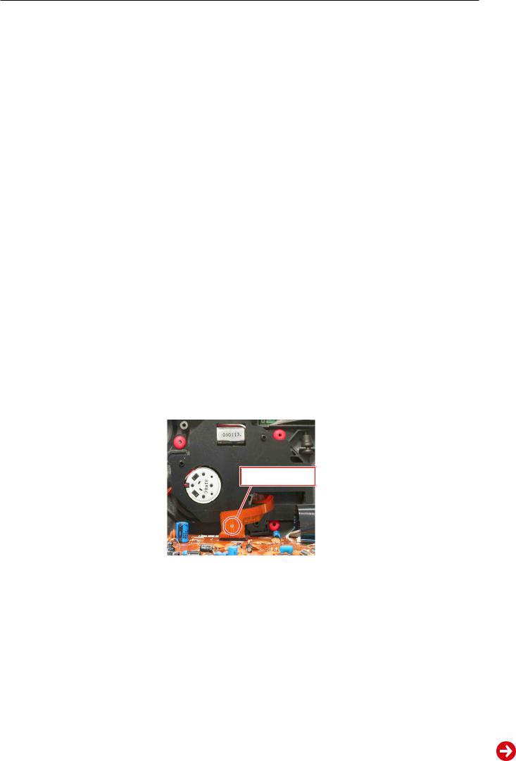
Bei Ausbau der CD-Servo-Platte / CD-Laser- einheit muss vor dem Lösen der
Steckverbindung eine Schutzlötstelle auf dem Flexprint der Lasereinheit angebracht werden, um eine Zerstörung der Laserdiode durch statische Aufladung zu vermeiden.
Beim Einbau einer neuen Lasereinheit (CDLaufwerk) muss nach Einstecken des Steckverbinders die werkseitig angebrachte Schutzlö tstelle entfernt werden!
Service Hints
Attention: Observe the ESD safety regulations  Disconnect the mains plug before opening the set.
Wiring
Before disconnecting any leads and especially the earth connecting leads observe the way they are routed to the individual assemblies.
On completion of the repairs the leads must be laid out as originally fitted at the factory to avoid later failures or disturbances.
Schutzlötstelle protective soldered joint
CD Section 
When removing the Laser pick-up, the flexprint must be provided with a protective soldered joint before unplugging the connectors to avoid damage to the Laser diode by static charges.
When inserting the new Laser pick-up (CD drive mechanism) the soldered joint fitted at the factory must be removed after the connectors are plugged in.
1 - 3
GRUNDIG Service |
Ovation CDS 6380 S |
Ausbauhinweise
Bevor Sie Leitungen lösen, muss die Leitungsverlegung beachtet werden. Nach erfolgter Reparatur ist es notwendig, die Leitungsführung in den werkseitigen Zustand zu versetzen.
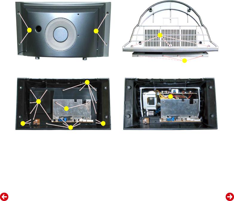
1. Gehäuserückteil
–4 Schrauben A(Fig. 1) und 3 Schrauben B(Fig. 2) herausdrehen.
–Gehäusevorderteil unten nach vorne wegziehen und abnehmen.
–Gegebenenfalls Steckverbindungen lösen.
2. Lautsprecher-Abdeckung / Audio-Platte
–Gehäuserückteil abnehmen (Punkt 1).
–16 lange Schrauben C(Fig. 3) herausdrehen.
–4 kurze Schrauben D(Fig. 3) herausdrehen.
–2 Schrauben E(Fig. 3) herausdrehen und Isoliernippel abnehmen.
–Audio-Platte herausziehen und Lautsprecher-Abdeckung abnehmen.
–Gegebenenfalls Steckverbindungen lösen.
Montagehinweise:
–Das Klebeband muss zum Abdichten des Bass-Lautsprechers auf den Kanten des Lautsprecher-Gehäuses angebracht sein.
–4 kurze Schrauben an der Position D(Fig. 3) verwenden.
–Bei der Montage ist darauf zu achten, dass die 2 Abstandshalter auf
der Lautsprecher-Abdeckung angebracht sind. Zusätzlich müssen die Schrauben E (Fig. 3) über Isoliernippel hineingeschraubt werden.
Disassembly Instructions
Before disconnecting any leads observe the way they are routed. On completion of the repairs the leads must be laid out as originally fitted at the factory.
1.Cabinet Rear Part
–Undo 4 screws A (Fig. 1) and 3 screws B(Fig. 2).
–Pull away the cabinet front part on the upper side and remove.
–Unplug the connectors if necessary.
2.Loudspeaker cover / Audio PCB
–Remove the cabinet rear part (point 1).
–Undo 16 long screws C(Fig. 3).
–Undo 4 short screws D(Fig. 3).
–Undo 2 screws E (Fig. 3) and remove the insulation sockets.
–Pull out the Audio PCB and remove the loudspeaker cover.
–Unplug the connectors if necessary.
Reassembly:
–The adhesive tape must be fitTed at the edges of the loudspeaker to seal the subwoofer.
–Use 4 short screws at position D(Fig. 3).
–When reassembling take care that the 2 spacers are mounted at the woofer cover. Additionally screws E (Fig. 3) must be screwed in together with the insulation sockets.
A |
A |
Fig. 1
C |
C |
E |
D |
D |
|
C |
Fig. 3
3. Netzteil-Platte
–Lautsprecher-Abdeckung abnehmen (Punkt 2).
–Schraube F (Fig. 4) herausdrehen.
–Netzteilplatte herausnehmen.
4. Buchsen-Platten (LINE / Kopfhörer)
–Lautsprecher-Abdeckung abnehmen (Punkt 2).
–2 Schrauben G(Fig. 5) herausdrehen.
–Buchsen-Platten herausnehmen.
B |
R |
Fig. 2
F |
Fig. 4
3.Power Supply PCB
–Remove the loudspeaker cover (point 2).
–Undo screw F(Fig. 4).
–Take out the Power Supply PCB.
4.Socket PCBs (LINE / Headphone)
–Remove the loudspeaker cover (point 2).
–Undo 2 screws G (Fig. 5).
–Take out the Socket PCBs.
1 - 4

GRUNDIG Service |
Ovation CDS 6380 S |
G |
G |
L |
HJ
J |
Fig. 5 |
Fig. 6 |
K |
M |
Fig. 7 |
M |
Schutzlötstelle protective soldered joint
Fig. 8
5. Tuner-Platte
–Gehäuserückteil abnehmen (Punkt 1).
–4 Schrauben H(Fig. 6) herausdrehen.
–Gegebenenfalls Steckverbindungen lösen und Tuner-Platte abnehmen.
6.MCU-/CD-Servo-Platte
–Gehäuserückteil abnehmen (Punkt 1).
–6 Schrauben J(Fig. 6) herausdrehen.
–Abdeckung mit Tuner-Platte abnehmen und gegebenenfalls Steckverbindungen lösen.
–6 Schrauben K(Fig. 7) herausdrehen.
–MCU-/CD-Servo-Platte abnehmen.
Achtung  : Vor dem Lösen der Steckverbindung zur Lasereinheit muss die Schutzlötstelle (Fig. 8) auf dem Flexprint zugelötet werden!
7. CD-Laufwerk 
–MCU-/CD-Servo-Platte ausbauen (Punkt 6).
–CD-Laufwerk herausnehmen.
Montagehinweis:
Beim Einbau einer neuen Lasereinheit (CD-Laufwerk) muss nach
Einstecken des Steckverbinders die werkseitig angebrachte Schutzlötstelle (Fig. 8) entfernt werden!
8.Tasten-Platte
–Gehäuserückteil abnehmen (Punkt 1).
–2 Schrauben L(Fig. 6) herausdrehen.
–Tasten-Platte nach vorne kippen (ausrasten) und abnehmen.
9.IR-Empfänger-Platte
–Gehäuserückteil abnehmen (Punkt 1).
–7 Schrauben M(Fig. 7) herausdrehen.
–Lautsprecher abnehmen.
–2 Schrauben herausdrehen und IR-Empfänger-Platte abnehmen.
5.Tuner PCB
–Remove the cabinet rear part (point 1).
–Undo 4 screws H (Fig. 6).
–Unplug the connectors if necessary and take out the Tuner PCB.
6.MCU/CD Servo PCB
–Remove the cabinet rear part (point 1).
–Undo 6 screws J (Fig. 6).
–Remove the cover with Tuner PCB and unplug the connectors if necessary.
–Undo 6 screws K (Fig. 7).
–Remove the MCU/CD Servo PCB.
Attention  : Before unplugging the connectors to the Laser pick up the flexprint must be provided with a protective soldered joint (Fig. 8).
7.CD Mechanism 
–Remove the MCU/CD Servo PCB (point 6).
–Remove the CD mechanism.
Reassembly:
When inserting a new Laser pick-up (CD mechanism) the soldered joint (Fig. 8) fitted at the factory must be removed after the connectors are plugged in!
8.Key PCB
–Remove the cabinet rear part (point 1).
–Undo 2 screws L (Fig. 6).
–Cant (disengage) the Key PCB to the front and remove it.
9.IR Receiver PCB
–Remove the cabinet rear part (point 1).
–Undo 7 screws M (Fig. 7).
–Remove the loudspeaker.
–Undo 2 screws und remove the IR Receiver PCB.
1 - 5

GRUNDIG Service |
Ovation CDS 6380 S |
10.Display-Platte
–CD-Servo-Platte ausbauen (Punkt 6).
–Steckverbindung (CN102) zur Klappe lösen.
–Führungen N(Fig. 9) vorsichtig aushebeln und Klappe abnehmen.
–2 Abdeckkappen O(Fig. 9) herausnehmen.
–6 Schrauben P(Fig. 9) herausdrehen.
–4 Schrauben R(Fig. 2) herausdrehen.
–Aluminium-Blende so weit von der Klappe lösen, bis die Aussparungen S (Fig. 10) zugänglich sind.
–Flachen Schraubendreher in die Aussparungen S (Fig. 10) stecken und verchromte Seitenteile nach außen schieben und abnehmen.
–Klappe vorsichtig an den Aussparungen T (Fig. 10) aufhebeln, Rastnasen U(Fig. 11) lösen und Klappe öffnen.
–10 Schrauben V(Fig. 12) herausdrehen.
–Display-Platte herausnehmen.
10.Display PCB
–Remove the CD Servo PCB (point 6).
–Unplug the connector (CN102) to the flap.
–Cancel carefully the guide N(Fig. 9) and remove the flap.
–Remove the 2 cover caps O (Fig. 9).
–Undo 6 screws P (Fig. 9).
–Undo 4 screws R (Fig. 2).
–Loose the aluminium faceplate from the flap as for as the cut-outs S
(Fig. 10) are accessible.
–Put in a flat screw driver in the cut-outs S(Fig. 10), slide out and remove the chromed side plates.
–Carefully dehisce the flap at the cut-outs T (Fig. 10), release the caches U(Fig. 11) and open the flap.
–Undo 10 screws V (Fig. 12).
–Take out the Display PCB.
O |
P |
N |
Fig. 9
U |
U |
Fig. 11
O |
N |
S |
T |
S |
Fig. 10
V |
Fig. 12
1 - 6

GRUNDIG Service |
Ovation CDS 6380 S |
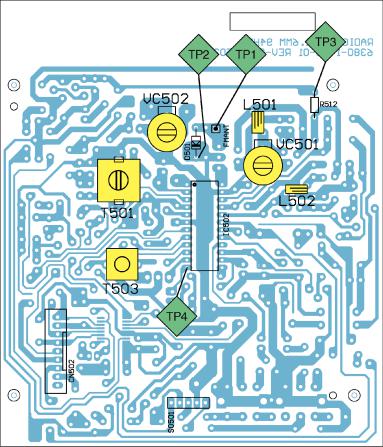
Abgleichvorschriften
1. Tuner
Messgeräte: Mess-Sender, Digital-Voltmeter
Abgleich |
Vorbereitung |
Abgleichvorgang |
|
|
|
1. MW-Oszillator |
Digital-Voltmeter an Messpunkt TP3. |
Bei 1620kHz mit T501 auf 8,4V ± 0,2V abgleichen. |
|
|
|
2. AM-ZF |
Mess-Sender über Loopantenne einkoppeln. |
Mit T503 auf Maximum abgleichen. |
|
f = 450kHz; ohne Modulation |
|
|
Digital-Voltmeter an Messpunkt TP4. |
|
|
|
|
3. MW-Eingangskreis |
Mess-Sender über Loopantenne einkoppeln. |
Wechselweise mit MW COIL (auf der Ferrit-Antenne) bei |
|
ohne Modulation |
558kHz und mit VC502 bei 1440kHz auf Maximum ab- |
|
Digital-Voltmeter an Messpunkt TP4. |
gleichen. |
|
|
|
4. FM-Oszillator |
Digital-Voltmeter an Messpunkt TP3. |
Bei 108,0MHz mit L502 (verbiegen) auf 7,2V ± 0,2V |
|
|
abgleichen. |
|
|
|
5. FM-HF-Kreis |
Mess-Sender an Antennen-Eingang (TP1 / TP2 Masse); |
Wechselweise mit L501 (verbiegen) bei 88,0MHz und mit |
|
ohne Modulation |
VC501 bei 106,0MHz auf NF-Maximum abgleichen. |
|
Digital-Voltmeter an Messpunkt TP4. |
|
|
|
|
2 - 1
GRUNDIG Service |
Ovation CDS 6380 S |
Adjustment Procedures
1. Tuner
Test equipment: Signal Generator, Digital Voltmeter
Adjustment |
Preparation |
Adjustment Procedure |
|
|
|
1. MW Oscillator |
Digital Voltmeter to Testpoint TP3. |
At 1620kHz adjust T501 for 8.4V ± 0.2V. |
|
|
|
2. AM IF |
Couple Signal Generator via Loop Antenna. |
Adjust T503 for maximum. |
|
f = 450kHz; no modulation |
|
|
Digital Voltmeter to Testpoint TP4. |
|
|
|
|
3. MW Pre Stage |
Couple Signal Generator via Loop Antenna. |
Adjust alternating with MW COIL (on the ferrite antenna) |
|
no modulation |
at 558kHz and with VC502 at 1440kHz for maximum. |
|
Digital Voltmeter to Testpoint TP4. |
|
|
|
|
4. FM Oscillator |
Digital Voltmeter to Testpoint TP3. |
At 108.0MHz adjust (bend) L502 for 7.2V ± 0.2V. |
|
|
|
5. FM Pre Stage |
Signal Generator to Aerial Input (TP1 / TP2 Ground); |
Adjust alternating with L501 (bend) at 88.0MHz and with |
|
no modulation |
VC501 at 106.0MHz for AF Maximum. |
|
Digital Voltmeter to Testpoint TP4. |
|
|
|
|
2 - 2
 Loading...