


Goodman GMSS920402BNAA, GMSS920603BNAA, GMSS920803BNAA, GMSS920804CNAA, GMSS920805CNAA User Manual
...Service Instructions
GMSS9*/GCSS9*/AMSS9*/ ACSS9*
Single Stage Gas Furnaces
and Accessories
This manual is to be used by qualified, professionally trained HVAC technicians only. Goodman does not assume any responsibility for property damage or personal injury due to improper service procedures or services performed by an unqualified person. The material in this manual does not supercede manufacturer's installation and operation instructions.
is a registered trademark of Maytag Corporation or its related companies and is used under license to Goodman Company, L.P., Houston, TX. All rights reserved.
Copyright © 2014 Goodman Manufacturing Company, L.P.
RS6612012
August 2014
TABLE OF CONTENTS
IMPORTANT INFORMATION .......................... |
2 - 6 |
PRODUCT IDENTIFICATION .......................... |
7-11 |
INSTALLATION CONSIDERATIONS .......... |
12 - 30 |
SYSTEM OPERATION ...................................... |
31 |
ACCESSORIES ........................................... |
3237 |
SERVICING TABLE OF CONTENTS |
................ 38 |
TROUBLESHOOTING ................................. |
4243 |
SERVICING .................................................. |
4454 |
MAINTENANCE ............................................ |
5557 |
IMPORTANT INFORMATION
Pride and workmanship go into every product to provide our customers with quality products. It is possible, however, that during its lifetime a product may require service. Products should be serviced only by a qualified service technician who is familiar with the safety procedures required in the repair and who is equipped with the proper tools, parts, testing instruments and the appropriate service manual. REVIEW ALL SERVICE INFORMATION IN THE
APPROPRIATE SERVICE MANUAL BEFORE BEGINNING REPAIRS.
IMPORTANT NOTICES FOR CONSUMERS AND SERVICERS
 RECOGNIZE SAFETY SYMBOLS, WORDS AND LABELS
 WARNING
TO PREVENT THE RISK OF PROPERTY DAMAGE, PERSONAL INJURY, OR DEATH,
DO NOT STORE COMBUSTIBLE MATERIALS OR USE GASOLINE OR OTHER
FLAMMABLE LIQUIDS OR VAPORS IN THE VICINITY OF THIS APPLIANCE.
 WARNING
GOODMAN WILL NOT BE RESPONSIBLE FOR ANY INJURY OR PROPERTY DAMAGE ARISING FROM IMPROPER SERVICE OR SERVICE PROCEDURES. IF YOU INSTALL OR PERFORM SERVICE ON THIS UNIT, YOU ASSUME RESPONSIBILITY FOR ANY PERSONAL INJURY OR PROPERTY DAMAGE WHICH MAY RESULT. MANY JURISDICTIONS REQUIRE A LICENSE TO INSTALL OR SERVICE HEATING AND AIR CONDITIONING EQUIPMENT.
 WARNING
HIGH VOLTAGE
DISCONNECT ALL POWER BEFORE SERVICING OR
INSTALLING THIS UNIT. MULTIPLE POWER SOURCES MAY
BE PRESENT. FAILURE TO DO SO MAY CAUSE PROPERTY
DAMAGE, PERSONAL INJURY OR DEATH.
2

IMPORTANT INFORMATION
Special Warning for Installation of Furnace or Air Handling Units in
Enclosed Areas such as Garages, Utility Rooms or Parking Areas
Carbon monoxide producing devices (such as an automobile, space heater, gas water heater, etc.) should not be operated in enclosed areas such as unventilated garages, utility rooms or parking areas because of the danger of carbon monoxide (CO) poisoning resulting from the exhaust emissions. If a furnace or air handler is installed in an enclosed area such as a garage, utility room or parking area and a carbon monoxide producing device is operated therein, there must be adequate, direct outside ventilation.
This ventilation is necessary to avoid the danger of CO poisoning which can occur if a carbon monoxide producing device continues to operate in the enclosed area. Carbon monoxide emissions can be (re)circulated throughout the structure if the furnace or air handler is operating in any mode.
CO can cause serious illness including permanent brain damage or death.
To locate an authorized servicer, please consult your telephone book or the dealer from whom you purchased this product. For further assistance, please contact:
CONSUMER INFORMATION LINE |
CONSUMER INFORMATION LINE |
GOODMAN® BRAND PRODUCTS |
AMANA® BRAND PRODUCTS |
TOLL FREE |
TOLL FREE |
1-877-254-4729 (U.S. only) |
1-877-254-4729 (U.S. only) |
email us at: |
email us at: hac.consumer.affairs@amanahvac.com |
customerservice@goodmanmfg.com |
fax us at: (731) 856-1821 |
fax us at: (731) 856-1821 |
(Not a technical assistance line for dealers.) |
(Not a technical assistance line for dealers.) |
|
Outside the U.S., call 1-713-861-2500.
(Not a technical assistance line for dealers.) Your telephone company will bill you for the call.
3
IMPORTANT INFORMATION
FOR YOUR SAFETY
READ BEFORE OPERATING
WARNING: If you do not follow these instructions explosion may result causing property damage, personal injury or loss of life.
A.This appliance does not have a pilot. It is equipped with an ignition device which automatically lights the burner. Do not try to light the burner by hand.
B. BEFORE OPERATING smell all around the appliance area for gas. Be sure to smell next to the floor because some gas is heavier than air and will settle on the floor.
WHAT TO DO IF YOU SMELL GAS  Do not try to light any appliance.
  Do not touch any electric switch; do not use any phone in your building.
  Immediately call your gas supplier from a neighbor's phone. Follow the gas supplier's instructions.
  If you cannot reach your gas supplier, call the fire department.
C.Use only your hand to push in or turn the gas control lever. Never use tools. If the lever will not push in or turn by hand, don't try to repair it, call a qualified service technician. Force or attempted repair may result in a fire or explosion.
D.Do not use this appliance if any part has been underwater. Immediately call a qualified service technician to inspect the appliance and to replace any part of the control system and any gas control which has been underwater.
LIRE AVANT DE METTRE
EN MARCHELIRE
AVERTISSEMENT: Quiconque ne respecte pas á la lettre les instructions dans le présent manuel risque de déclecher un incendie ou une explosion entraînant des dammages matériels, des lésions corporelles ou la perte de vies humaines.
A. Cet appareil ne comporte pas de veilleuse. Il est muni d'un dispositif d'allumage qui allume automatiquement le brûleur. Ne pas tenter d'allumer le brûleur manuellement.
B. AVANT DE LE FAIRE FONCTIONNER, renifler tout autour de l'appariel pour déceler
une odeur de gaz. Renifler près du plancher, car certains gaz sont plus lourds que l'air et peuvent s'accumuler au niveau du so.l
QUE FAIRE S'IL Y A UNE ODEUR DE GAZ  Ne pas tenter d'allumer l'appariel
  Ne toucher aucun interrupteur électrique; n'utiliser aucun téléphone dans le bâtiment.
  Appeler immédiatement le fournisseur de gaz en employant le téléphone dún voisin. Respecter à la lettre les instructions du fournisseur de gaz.
  Si personne ne répond, appeler le service des incendies.
C. Ne pousser ou tourner le levier d'admission du gaz qu'à la main; ne jamais emploer d'outil à cet effet. Si la manette reste coincée, ne pas tenter de la réparer; appeler un technicien qualifié. Quiconque tente de forcer la manette ou de la reparer peut déclencher une explosion ou un incendie.
D. Ne pas se servir de cet appareil s'il a été plongé dans l'eau, complètement ou en partie. Appeler un technicien qualifié pour inspecter l'appareil et remplacer tout partie du système de contrôle et toute commande qui ont été plongés dans l'eau.
|
OPERATING INSTRUCTIONS |
|
MISE EN MARCHE |
|
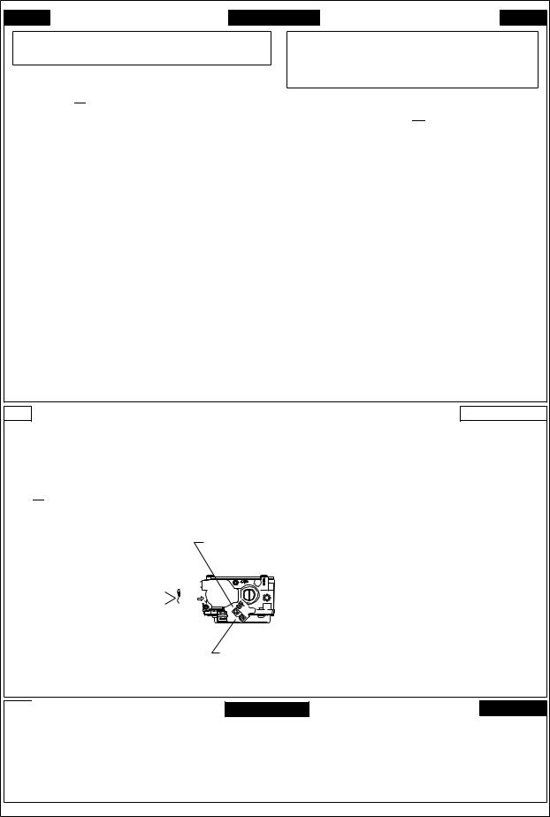
1.STOP! Read the safety information above on this label.
2.Set the thermostat to lowest setting.
3.Turn off all power to the appliance.
4.This appliance is equipped with an ignition. device which automatically lights the burner. Do not try to light the burner by hand.
5. |
Push the gas control lever to "OFF" Position. |
|
|
|||||
|
Do not force. |
|
|
|
|
|
|
|
6. Wait five (5) minutes to clear out any gas. Then |
|
|
||||||
|
smell for gas, including near the floor. If you |
|
|
|||||
|
then smell gas, STOP! Follow |
"B" |
|
|
||||
|
in the safety. information above |
|
|
|||||
|
on this label if you don't smell |
|
|
|
|
|
|
|
|
gas, go to next step. |
GAS |
|
|
||||
7. Push gas control lever |
|
|
||||||
INLET |
|
|
|
|||||
|
to "ON". |
|
|
|
||||
|
|
|
|
|
|
|
|
|
8. Replace access panel. |
|
|
|
|
|
|
|
|
|
|
|
|
|
|
|
||
9. Turn on all electric |
ARRIVEE |
|
|
|||||
|
|
|||||||
|
power to the appliance. |
DU GAZ |
|
|
||||
10.Set thermostat to desired setting. |
|
|
||||||
11.If the appliance will not operate, |
|
|
||||||
|
follow the instructions "To Turn |
|
|
|
|
|
|
|
|
Off Gas To Appliance" and call your |
|
|
|||||
|
service technician or gas company. |
|
|
|||||
|
1. |
|
. |
2. |
|
3. |
||
|
||
|
4. |
|
|
5. |
|
|
6. |
ROBINET A GAZ MANUEL, EN POS "ON/MARCHE"
7. |
8. |
9. |
10. |
11. |
MANUAL GAS
LEVER SHOWN
IN ON POSITION
ARRETÊR! Lisez les instructions de sécurité sur la portion supérieure de cette étiquette. Régler le thermostat à la température la plus basse Couper l'alimentation électrique de l'appareil. Cet appareil ménager étant doté d'un système d'allumage automatique, ne pas essayer à allumer le brûleur manuellement.
Pousse le levier du contrôle du gaz à "OFF/ ARRET" position.
Attendre cinq (5) minutes pour laisser echapper tout le gaz. Renifler tout autour de l'appareil, y compris près du plancher, pour déceler une odeur de gaz. Si c'est le cas, ARRETER! Passer à l'étape B des instructions de sécuritié sur la portion supérieure de cette étiquette. S'il n'y a pas d'odeur de gaz, passer à l'étape suivanté. Pousse le levier du contrôle du gaz à "ON/MARCHE" position. Remettre en place le panneau d'accés. Mettre l'appareil sous tension. Régler le thermostat à la température desirée. Si l'appareil ne se met pas en marche, suiyre les instructions intitulées. Comment coupler l'admission de gaz de l'appereil et appeler un technicien qualifié ou le fourrnisseur de gaz.
 TO TURN OFF GAS TO APPLIANCE
1.Set the thermostat to lowest setting.
2.Turn off all electric power to the appliance if service is to be performed.
3. |
Push the gas control lever to "OFF" Position. |
4. |
Do not force. |
Replace control access panel. |
POUR COUPER L'ADMISSION
DE GAZ DE L'APPAREIL
1.Régler le thermostat à la température la plus basse.
2.Couper l'alimentation électrique de l'appareil s'il faut procéder à des opérations d'entretien.
3.Pousse le levier du contrôle du gaz à "OFF / ARRET" position.
Ne pas forcer.
4.Remettre en place le panneau d'accès.
11072712
4
IMPORTANT INFORMATION
FOR YOUR SAFETY |
|
LIRE AVANT DE METTRE |
||
READ BEFORE OPERATING |
EN MARCHELIRE |
|||
WARNING: If you do not follow these instructions |
AVERTISSEMENT: Quiconque ne respecte pas à |
|||
exactly,a fire or explosion may result causing property |
la lettre les instructions dans le presént manuel |
|||
damage,personal injury or loss of life. |
|
risque de déclencher un incendie ou une explosion |
||
A.This appliance does not have a pilot. It is equipped |
entraînant des dommages matériels, des lesions |
|||
corporelles ou la perte de vies humaines. |
||||
with an ignition device which automatically lights |
Cet appareil ne comporte pas de veilleuse. Ilest |
|||
the burner. Do not tryto light the burner by hand. |
||||
A. |
||||
|
|
|
muni d'undispositif d'allumage qui allume |
|
B.BEFOREOPERATING smell all around the appliance |
automatiquement le brûleur. Ne pas tenter |
|||
area for gas. Be sure to smell next to the floor |
|
d'allumer le brûleur manuellement. |
||
because some gas is heavier than air and will |
|
B.AVANT DE LE FAIRE FONCTIONNER, |
||
settle on the floor. |
|
|
renifler tout autour del'appariel pour decéler |
|
WHAT TO DO IF YOU SMELL GAS |
|
une odeur de gaz. Renifler prés du plancher, car |
||
|
certains gaz sont plus lourds que l'airet |
|||
Do not try to light any appliance. |
|
|||
|
peuvent s'accumuler au niveau du sol. |
|||
Do not touch any electric switch; |
|
|||
|
QUEFAIRE S'IL Y A UNE ODEUR DE GAZ |
|||
do not use any phone in your building. |
|
|||
Immediately call your gas supplier from a neighbor's |
Ne pas tenter d'allumer d'appareils. |
|||
Ne toucher à aucun interrupteur; ne pas vous servir |
||||
phone. Follow the gas supplier's instructions. |
||||
des téléphones dans le bâtiment. |
||||
If you cannot reach your gas supplier, |
|
|||
|
Appelez immédiatement votre fournisseur de gaz depuis |
|||
call the fire department. |
|
|
||
|
|
un voisin. Suivez les instructions du fournisseur de gaz |
||
|
|
|
||
C.Use only your hand to push in or turn the gas control lever. |
Sivous ne pouvez rejoindre le fournisseur de gaz, |
|||
appelez le service des incendies.» |
||||
Never use tools. If the lever will not push in or turn by |
C.Ne pousser ou tourner la manette d'admission du gaz |
|||
hand, don't try to repair it,call a qualified service |
||||
qu'à la main. Ne jamais emploer d'outil à cette fin. |
||||
technician. Force or attempted repair may result in a fire |
||||
Si la manette reste coincée, ne tenter pas de la |
||||
or explosion. |
|
|
||
|
|
réparer; appelez un technicien qualifié. Quiconque |
||
D.Do not use this appliance if any part has been underwater. |
tente de forcer la manette ou de la réparer peut |
|||
Immediately call a qualified service technician to inspect |
provoquer uneexplosion ou un incendie.» |
|||
the appliance and to replace any part of the control |
D.Ne pas se servir de cet appareil s'il a été plongé dans |
|||
system and any gas control which has been underwater. |
||||
|
|
|
l'eau, même partiellement. Faire inspecter l'appareil |
|
|
|
|
par un technicien qualifié et remplacer toutr partie du |
|
|
|
|
systéme de contrôle et toute commande qui ont été |
|
|
|
|
plongées dans l'eau.» |
|
OPERATING INSTRUCTIONS |
MISEEN MARCHE |
|||
1. STOP. Read the safety information above on |
1. ARRÊTEZ Lisez les instructions de sécurité dans la |
|||
this label. |
|
|
. section supérieure de cette étiquette. |
|
2.Set the thermostat to lowest setting. |
|
2.Régler le thermostat à la température la plus basse. |
||
3.Turn off all electric power to the appliance. |
|
3.Couper l'alimentation électrique de l'appareil. |
||
4.This appliance is equipped with an ignition |
|
4.Cet appareil menager etant dote d'un systeme |
||
device which automatically lights the burner. |
|
d'allumage automatique, ne pas essayer à |
||
Do not try to light the burner by hand. |
|
allumer le brûleur manuellement. |
||
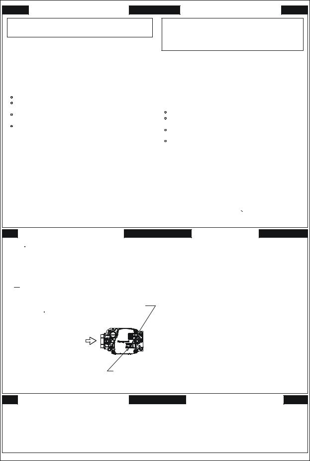
5. Push the gas control lever to |
"OFF” Position. |
5.Pousse le levier du contrÔle du gaz a "OFF/ARRET” |
||
Do not force. |
|
|
position. |
|
6.Wait five (5) minutes to clear out any gas.Then |
|
6.Attendre cinq (5) minutes pour laisser echapper tout le |
||
smell for gas, including near the floor. If you |
ROBINETAGAZ |
gaz. Renifler tout autour de l'appareil, y comprisprés du |
||
then smell gas, STOP. Follow "B" |
MANUEL,ENPOS |
plancher, pour déceler une odeur de gaz. Si c'est le cas, |
||
"ON/MARCHE" |
ARRÊTEZ. Passer à l'etape B des instructions de securite |
|||
in the safety information above |
|
|||
|
|
|||
on this label if you don't smell |
GAS |
|
sur la portion superieure de cette etiquette. |
|
gas,go to next step. |
|
S'il n'y a pas d'odeur de gaz, passer à l'etàpe suivante. |
||
INLET |
|
7.Pousse le levier du contrôle du gaz à "ON/MARCHE” |
||
7.Push gas control lever |
|
|||
|
|
|||
to "ON". |
|
|
position. |
|
8.Replace access panel. |
ARRIVEE |
|
8.Remettre en place le panneau d'accés. |
|
9. Turn on all electric |
DUGAZ |
|
9.Mettre l'appareil sous tension. |
|
power to the appliance. |
|
|
10.Régler le thermostat à la température désirée. |
|
10.Setthermostattodesiredsetting. |
MANUAL GAS |
11.Si l'appareil ne se met pas en marche,suivre les |
||
11.If the appliance will not operate, |
instructions intitulées Comment couper l'admission |
|||
follow the instructions “ToTurn |
|
LEVER SHOWN |
de gaz de l'appareil et appeler un technicien |
|
Off Gas ToAppliance" and call your |
IN "ON" POS |
qualifié ou le fournisseur de gaz. |
||
service technician or gas company. |
|
|
||
TOTURNOFFGASTOAPPLIANCE |
POUR COUPER L'ADMISSION |
|||
1.Set the thermostat to lowest setting. |
|
DE GAZ DE L'APPAREIL |
||
|
1.Régler le thermostat à la température la plus bassé. |
|||
2. Turn off all electric power to the appliance |
2.Couper l'alimentation électrique de l'appareil s'il |
|||
if service is to be performed. |
|
faut procéder à des operations d'entretien. |
||
|
3.Pousse le levier du contrôle du gaz à "OFF/ARRET" |
|||
3.Push the gas control lever to "OFF” Position. |
||||
position. |
||||
Do not force. |
|
|
||
|
|
Ne pas forcer. |
||
4.Replace control access panel. |
|
4.Remettre en place le panneau d'accés. |
||
0140F00681 REV A
5
IMPORTANT INFORMATION
 FOR YOUR SAFETY READ BEFORE OPERATING
If you do not follow these instructions exactly, a fire or explosion may result causing property damage, personal injury or loss of life.
A. This appliance does not have a pilot. It is equipped with an ignition device which
automatically lights the burners. Do not try to light the burners by hand.
B. BEFORE OPERATING smell around the appliance area for gas. Be sure to
smell next to the floor because some gas is heavier than air and will settle on the floor.
WHAT TO DO IF YOU SMELL GAS  Do not try to light any appliance.
 Do not touch any electric switch;
do not use any telephone in your building.
 Immediately call your supplier
from a neighbor's phone. Follow the gas suppliers instructions.
 If you cannot reach your gas supplier, call the fire department.
C. Use only your hand to move the gas control switch or knob. Never use tools. If the gas control switch or knob will not operate, don't try to repair it, call a qualified service technician. Force or attempted repair may result in a fire or explosion.
D. Do not use this appliance if any part has been under water. Immediately call
a qualified service technician to inspect the appliance and to replace any part of the control system and any gas control which has been under water.
 OPERATING INSTRUCTIONS
1.STOP! Read the safety information above on this label.
2.Set the thermostat to lowest setting.
3.Turn off all electric power to the appliance.
4.This appliance is equipped with an automatic ignition system which automatically lights the burners. Do not
try to light the burners by hand.
5.Remove control access panel.
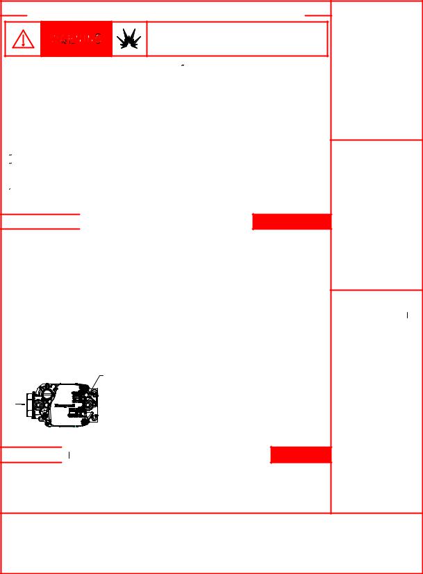
6.Move the gas control switch or knob to "OFF".
GAS CONTROL |
SWITCH SHOWN |
IN "ON" POSITION |
7. Wait five (5) minutes to clear out any gas. If you then smell gas, STOP! Follow "B" in the safety information
above on this label. If you don't smell gas, go to the next step.
8.Move the gas control switch or knob to "ON".
9.Replace control access panel.
10.Turn on all electric power to the appliance.
11.Set the thermostat to the desired setting.
12.If the appliance will not operate,
follow the instructions "To Turn Off Gas To Appliance" and call your service technician or gas supplier.
 TO TURN OFF GAS TO APPLIANCE
1. |
Set the thermostat to its lowest setting. |
4. |
Move the gas control switch or knob |
2. |
Turn off all electric power to the |
to "OFF". Do not force. |
|
appliance if service is to be performed. |
5. |
Replace control access panel. |
|
3. |
Remove control access panel. |
|
|
WARNING: Improper
installation, adjustment, alteration, service or
maintenance can cause injury or property damage.
Refer to the user's information manual provided with this furnace. For assistance
or additional information consult a qualified
installer, service agency or the gas supplier.
This furnace must be installed in accordance
with the manufacturers instructions and local
codes. In the absence of local codes, follow
the National Fuel Gas Code, ANSI Z223.1.
WARNING: If not installed, operated and maintained in
accordance with the manufacturer's instructions, this product could expose
you to substances in fuel combustion
which can cause death or serious
illness and which are known to the
State of California to cause cancer, birth
defects or other reproductive harm.
This product contains fiberglass insulation.
Fiberglass insulation contains a chemical known by the State of
California to cause cancer.
FOR YOUR SAFETY Do not store or use gasoline or other flammable vapors and liquids in the vicinity of this or any other appliance.
6

PRODUCT IDENTIFICATION
The model and manufacturing number are used for positive identification of component parts used in manufacturing. Please use these numbers when requesting service or parts information.
* |
M |
S |
S |
9 |
6 |
0 |
6 |
0 |
3 |
B |
N |
A |
A |
1 |
2 |
3 |
4 |
5 |
6 |
7 |
8 |
9 |
10 |
11 |
12 |
13 |
14 |
Brand |
|
|
|
|
|
|
|
|
|
|
|
|
Minor Revision |
A- Amana® G- Goodman® |
|
|
|
|
|
|
|
|
|
|
|
|
A - Initial Release |
|
|
|
|
|
|
|
|
|
|
|
|
|
B - 1st Revision |
Configuration |
|
|
|
|
|
|
|
|
|
|
|
|
|
M - Upflow/Horizontal |
|
|
|
|
|
|
|
|
|
|
|
|
Major Revision |
C - Downflow/Horizontal |
|
|
|
|
|
|
|
|
|
|
|
|
A - Initial Release |
K - Dedicated Upflow |
|
|
|
|
|
|
|
|
|
|
|
|
B - 1st Revision |
D - Dedicated Downflow |
|
|
|
|
|
|
|
|
|
|
|
|
|
|
|
|
|
|
|
|
|
|
|
|
|
|
Nox |
Airflow |
|
|
|
|
|
|
|
|
|
|
|
|
N - Natural Gas |
C - Variable Speed/ComfortNet |
|
|
|
|
|
|
|
|
|
|
|
|
X - Low Nox |
E - High Efficiency |
|
|
|
|
|
|
|
|
|
|
|
|
|
S - Single Speed |
|
|
|
|
|
|
|
|
|
|
|
|
Cabinet Width |
|
|
|
|
|
|
|
|
|
|
|
|
|
A - 14" |
Gas Valve Stages |
|
|
|
|
|
|
|
|
|
|
|
|
B - 17.5" |
M - Modulating |
|
|
|
|
|
|
|
|
|
|
|
|
C - 21" |
V - 2 Stage |
|
|
|
|
|
|
|
|
|
|
|
|
D - 24.5" |
H - Convertible 2 Stage |
|
|
|
|
|
|
|
|
|
|
|
|
|
S - Single Stage |
|
|
|
|
|
|
|
|
|
|
|
|
Maximum CFM |
|
|
|
|
|
|
|
|
|
|
|
|
|
3 - 1200 CFM |
AFUE |
|
|
|
|
|
|
|
|
|
|
|
|
4 - 1600 CFM |
97 - 97% AFUE |
|
|
|
|
|
|
|
|
|
|
|
|
5 - 2000 CFM |
80 - 80% AFUE |
|
|
|
|
|
|
|
|
|
|
|
|
|
MBTU/h 040 - 40,000 060 - 60,000 080 - 80,000
100 - 100,000
120 - 120,000
7

PRODUCT IDENTIFICATION
MODEL # |
MFG # |
DESCRIPTION |
|
|
|
|
|
|
GMSS920402BNAA |
|
|
|
GMSS920603BNAA |
Goodman® Brand 92%Single Stage Gas Furnace. 34.5" tall, Upflow/Horizontal |
|
|
GMSS920803BNAA |
||
|
Installation, 1-stage gas valve induced draft. PSC motor. 120-volt silicon carbide |
||
|
GMSS920804CNAA |
||
GMSS92 |
17-second hot surface ignition. Left or right gas pipe entry. The furnace also |
||
GMSS920805CNAA |
|||
|
features an aluminized steel tubular heat exchanger. Available cabinet widths |
||
|
GMSS921004CNAA |
||
|
are 17.5", 21", and 24.5" wide. |
||
|
GMSS921005CNAA |
||
|
|
||
|
GMSS921205DNAA |
|
|
|
|
|
|
|
GCSS920402BNAA |
Goodman® Brand 92%Single Stage Gas Furnace. 34.5" tall, |
|
|
Downflow/Horizontal Installation, 1-stage gas valve induced draft. PSC motor. |
||
|
GCSS920603BNAA |
||
GCSS92 |
120-volt silicon carbide 17-second hot surface ignition. Left or right gas pipe |
||
GCSS920804CNAA |
|||
|
entry. The furnace also features an aluminized steel tubular heat exchanger. |
||
|
GCSS921005CNAA |
||
|
Available cabinet widths are 17.5" and 21" wide. |
||
|
|
||
|
|
|
|
|
GMSS960402BNAA |
|
|
|
GMSS960603BNAA |
Goodman® Brand 96%Single Stage Gas Furnace. 34.5" tall, Upflow/Horizontal |
|
|
GMSS960803BNAA |
Installation,1-stage gas valve induced draft. PSC motor. 120 volt silicon carbide |
|
GMSS96 |
GMSS960804CNAA |
17-second hot surface ignition. Left or right gas pipe entry. The furnace also |
|
|
GMSS960805CNAA |
features an aluminized steel tubular heat exchanger. Available cabinet widths |
|
|
GMSS961005CNAA |
are 17.5" 21" and 24.5" wide. |
|
|
GMSS961205DNAA |
|
|
|
|
|
|
|
GCSS960402BNAA |
Goodman® Brand 96%Single Stage Gas Furnace. 34.5" tall, |
|
|
GCSS960603BNAA |
Downflow/Horizontal Installation, 1-stage gas valve induced draft. PSC motor. |
|
GCSS96 |
GCSS960804CNAA |
120-volt silicon carbide 17-second hot surface ignition. Left or right gas pipe |
|
|
GCSS961005CNAA |
entry. The furnace also features an aluminized steel tubular heat exchanger. |
|
|
GCSS961205DNAA |
Available cabinet widths are 17.5", 21", and 24.5" wide. |
|
|
|
|
8

PRODUCT IDENTIFICATION
MODEL # |
MFG # |
DESCRIPTION |
|
|
|
|
|
|
AMSS920402BNAA |
|
|
|
AMSS920603BNAA |
Amana® Brand 92%Single Stage Gas Furnace. Upflow/Horizontal Installation, |
|
|
AMSS920803BNAA |
||
|
34.5" tall, 1-stage gas valve induced draft. PSC motor. 120-volt silicon carbide 17- |
||
AMSS92 |
AMSS920804CNAA |
||
second hot surface ignition. Left or right gas pipe entry. The furnace also features |
|||
AMSS920805CNAA |
|||
|
a stainless steel tubular heat exchanger. Available cabinet widths are 17.5", 21", |
||
|
AMSS921004CNAA |
||
|
and 24.5" wide. |
||
|
AMSS921005CNAA |
||
|
|
||
|
AMSS921205DNAA |
|
|
|
|
|
|
|
ACSS920402BNAA |
Amana® Brand 92%Single Stage Gas Furnace. Downflow/Horizontal Installation, |
|
|
34.5" tall, 1-stage gas valve induced draft. PSC motor. 120-volt silicon carbide 17- |
||
ACSS92 |
ACSS920603BNAA |
||
second hot surface ignition. Left or right gas pipe entry.The furnace also features |
|||
ACSS920804CNAA |
|||
|
a stainless steel tubular heat exchanger. Available cabinet widths are 17.5" and |
||
|
ACSS921005CNAA |
||
|
21" wide. |
||
|
|
||
|
|
|
|
|
AMSS960402BNAA |
Amana® Brand 96%Single Stage Gas Furnace. Upflow/Horizontal Installation, |
|
|
AMSS960603BNAA |
||
|
AMSS960803BNAA |
34.5" tall, 1-stage gas valve induced draft. PSC motor. 120-volt silicon carbide 17- |
|
AMSS96 |
AMSS960804CNAA |
second hot surface ignition. Left or right gas pipe entry. The furnace also features |
|
|
AMSS960805CNAA |
a stainless steel tubular heat exchanger. Available cabinet widths are 17.5" 21" |
|
|
AMSS961005CNAA |
& 24.5 wide. |
|
|
AMSS961205DNAA |
|
|
|
|
|
|
|
ACSS960402BNAA |
Amana® Brand 96%Single Stage Gas Furnace. Downflow/Horizontal |
|
|
ACSS960603BNAA |
Installation, 34.5" tall, 1-stage gas valve induced draft. PSC motor. 120volt |
|
ACSS96 |
ACSS960804CNAA |
silicon carbide 17-second hot surface ignition. Left or right gas pipe entry. The |
|
|
ACSS961005CNAA |
furnace also features a stainless steel tubular heat exchanger. Available cabinet |
|
|
ACSS961205DNAA |
widths are 17.5", 21", and 24.5" wide. |
|
|
|
|
9
PRODUCT IDENTIFICATION
MODEL # |
MFG # |
DESCRIPTION |
|
|
|
|
|
|
|
Fossil Fuel Kit. The AFE18-60A control is designed for use where the indoor coil is |
|
|
|
located above/downstream of a gas or fossil fuel furnace when used with a heat pump. |
|
AFE18-60A |
N/A |
It will operate with single and two stage heat pumps and single and two stage |
|
furnaces. The AFE18-60A control will turn the heat pump unit off when the furnace is |
|||
|
|
||
|
|
turned on. An anti-short cycle feature initiates a 3 minute timed off delay when the |
|
|
|
compressor goes off. |
|
|
|
|
|
AMU1620 |
P1251305F |
|
|
AMU1625 |
P1251306F |
Media Air Cleaner. A high efficiency air filtration device designed to remove dirt, dust, |
|
AMU2020 |
P1251307F |
pollen and other microscopic particles from the air passing through it. Flexible |
|
AMU2025 |
P1251308F |
performance range up to 2,000 CFM capacity. The air cleaner should be installed in the |
|
|
|
system so that all the system air is circulated through the air cleaner. The air cleaner |
|
|
|
||
GMU1620 |
|
will only remove the airborne contaminants delivered to it. Maximum performance is |
|
GMU1625 |
N/A |
obtained when the system blower is set for continuous operation. Carbon filters |
|
GMU2020 |
(optional) are available. |
||
|
|||
GMU2025 |
|
|
|
|
|
|
|
ASAS-10 |
P1251301F |
Electronic Air Cleaner. The High-Efficiency Electronic Air Cleaner is designed to |
|
remove air contaminants down to .01 microns. Carbon filters (optional) remove odors. |
|||
ASAS-11 |
P1251302F |
||
Dual indicator lights show unit operation at a glance. Electronic proving switch cycles |
|||
ASAS-12 |
P1251303F |
||
the air cleaner On/Off with the system fan. Durable powder-coat paint finish resists |
|||
ASAS-18 |
P1251304F |
||
corrosion. |
|||
|
|
||
|
|
|
|
|
|
Counterflow Subbase Kit. For use with 34.5" down flow furnace models. These kits |
|
|
|
are available for the following furnace widths: 17.5" wide (CFSB17), 21" wide (CFSB21) |
|
CFSB17 |
N/A |
and 24.5" wide (CFSB24). The kits must be used to prevent excessive temperature |
|
CFSB21 |
from reaching combustible materials, if the furnace is installed on a combustible floor. |
||
CFSB24 |
|
This subbase effectively separated the furnace base and plenum from combustible |
|
|
|
materials. To ensure safe installation, do not install the counterflow floor base directly |
|
|
|
on carpeting, tile, or other combustible material other than wood flooring. |
|
|
|
|
10
PRODUCT IDENTIFICATION
MODEL # |
MFG # |
DESCRIPTION |
|
|
|
|
|
DCVK-20 |
|
Concentric Vent Kit. This kit is designed to allow terminations of a direct vent furnace |
|
(CVENT-2) |
N/A |
||
|
to be "concentrically" vented through a wall or roof. This kit allows a single penetration |
||
DCVK-30 |
|
to support terminations for both the vent/flue and the combustion air intake pipe. |
|
(CVENT-3) |
|
|
|
|
|
|
|
|
|
External Filter Rack Kit. For use with 34.5" up flow gas furnaces. This kit is intended to |
|
EFR02 |
N/A |
provide a location, external to the furnace casing for installation of a permanent filter. |
|
The rack is mounted over the indoor air blower compartment area of either side panel, |
|||
|
|
||
|
|
and provide filter retention as well as a location for attaching return air ductwork. |
|
|
|
|
|
|
N/A |
Side Wall Only Concentric Vent Kit. This kit is to be used with 2" - 3" vent systems. |
|
0170K00000S |
The vent kit must terminate outside the structure. This kit is NOT intended for use with |
||
|
|
single pipe (indirect vent) installations. |
|
|
|
|
|
|
N/A |
Side Wall Only Concentric Vent Kit. This kit is to be used with 2" vent systems. The |
|
0170K00001S |
vent kit must terminate outside the structure. This kit is NOT intended for use with |
||
|
|
single pipe (indirect vent) installation |
|
|
|
|
|
|
|
LP Gas Low Pressure Kit. Designed for use with furnaces converted to LP gas. The kit |
|
LPLP03 |
N/A |
monitors gas line pressure with a pressure switch and will open the circuit to the gas |
|
|
|
valve if the LP tank pressure gets low. |
|
|
|
|
|
LPM-07 |
N/A |
LP Conversion Kit Converts a 34.5" single stage furnace to operate on L.P. gas. The |
|
kit contains an L.P. gas valve and a set of six L.P. orifices. |
|||
|
|
||
|
|
|
|
|
N/A |
Drain Coupling Kit For use when the drain/vent elbow has been removed in a |
|
RF000142 |
horizontal left installation. This kit prevents condensate from getting in the inducer and |
||
|
|
routes the condensate to a drain. |
|
|
|
|
11
INSTALLATION CONSIDERATIONS
Safety
Please adhere to the following warnings and cautions when installing, adjusting, altering, servicing, or operating the furnace.
 WARNING
TO PREVENT PERSONAL INJURY OR DEATH DUE TO IMPROPER INSTALLATION, ADJUSTMENT, ALTERATION, SERVICE OR MAINTENANCE, REFER TO THIS MANUAL. FOR ADDITIONAL ASSISTANCE OR INFORMATION, CONSULT A QUALIFIED INSTALLER, SERVICE AGENCY OR THE GAS SUPPLIER.
 WARNING
THIS PRODUCT CONTAINS OR PRODUCES A CHEMICAL OR CHEMICALS WHICH MAY CAUSE SERIOUS ILLNESS OR DEATH AND WHICH ARE KNOWN TO THE STATE OF CALIFORNIA TO CAUSE CANCER, BIRTH DEFECTS OR OTHER REPRODUCTIVE HARM.
 WARNING
TO PREVENT POSSIBLE PROPERTY DAMAGE, PERSONAL INJURY OR DEATH DUE TO ELECTRICAL SHOCK, THE FURNACE MUST BE LOCATED TO PROTECT THE ELECTRICAL COMPONENTS FROM WATER.
Charge (ESD) Precautions
NOTE: Discharge body’s static electricity before touching unit. An electrostatic discharge can adversely affect electrical components.
Use the following precautions during furnace installation and servicing to protect the integrated control module from damage. By putting the furnace, the control, and the person at the same electrostatic potential, these steps will help avoid exposing the integrated control module to electrostatic discharge. This procedure is applicable to both installed and uninstalled (ungrounded) furnaces.
1.Disconnect all power to the furnace. Do not touch the integrated control module or any wire connected to the control prior to discharging your body’s electrostatic charge to ground.
2.Firmly touch a clean, unpainted, metal surface of the furnace near the control. Any tools held in a person’s hand during grounding will be discharged.
3.Service integrated control module or connecting wiring following the discharge process in Step 2. Use caution not to recharge your body with static electricity; (i.e., do not move or shuffle your feet, do not touch ungrounded objects, etc.). If you come in contact with an ungrounded object, repeat Step 2 before touching control or wires.
4.Discharge any static electricity from your body to ground before removing a new control from its container. Follow Steps 1 through 3 if installing the control on a furnace. Return any old or new controls to their containers before touching any ungrounded object.
Product Application
This product is designed for use as a residential home gas furnace. It is not designed or certified for use in mobile home, trailer, or recreational vehicle applications.
This furnace can be used in the following non-industrial commercial applications: Schools, Office buildings, Churches, Retail stores, Nursing homes, Hotels/motels, Common or office areas. In all applications, the furnace must be installed per the installation instructions.
Goodman® brand G*SS9* and Amana® brand A*SS9* furnaces are ETL certified. All furnaces are built for use with Natural gas but can be converted for use with LP gas.
(NOTE: If using propane gas, a propane conversion kit is required).
Goodman® brand G*SS9* and Amana® brand A*SS9* high efficiency furnaces are dual certified. Dual certification means that the combustion air inlet pipe is optional and the furnace can be vented as a:
Non-direct vent (single pipe) central forced air furnace in which combustion air is taken from the installation area or from air ducted from the outside or,
Direct vent (dual pipe) central forced air furnace in which all combustion air supplied directly to the furnace burners through a special air intake system outlined in this manual and the installation instructions.
To ensure proper installation, operation and servicing, thoroughly read the installation and service manuals for specifics pertaining to the installation, servicing and application of this product.
 WARNING
POSSIBLE PROPERTY DAMAGE, PERSONAL INJURY OR DEATH DUE TO FIRE, EXPLOSION, SMOKE, SOOT, CONDENSTAION, ELECTRICAL SHOCK OR CARBON MONOXIDE MAY RESULT FROM IMPROPER INSTALLATION, REPAIR, OPERATION, OR MAINTENANCE OF THIS PRODUCT.
 WARNING
TO PREVENT PROPERTY DAMAGE, PERSONAL INJURY OR DEATH DUE TO FIRE, DO NOT INSTALL THIS FURNACE IN A MOBILE HOME, TRAILER, OR RECREATIONAL VEHICLE.
To ensure proper furnace operation, install, operate, maintain and service the furnace in accordance with the installation, operation and service instructions, all local building codes and ordinances. In their absence, follow the latest edition of the National Fuel Gas Code (NFPA 54/ANSI Z223.1), and/or CAN/CGA B149 Installation Codes, local plumbing or waste water codes, and other applicable codes.
A copy of the National Fuel Gas Code (NFPA 54/ANSI Z223.1) can be obtained from any of the following:
American National Standards Institute
12
INSTALLATION CONSIDERATIONS
1430 Broadway
New York, NY 10018
National Fire Protection Association
1 Batterymarch Park
Quincy, MA 02269
CSA International
8501 East Pleasant Valley
Cleveland, OH 44131
A copy of the CAN/CGA B149 Installation Codes can be obtained from:
CSA International
178 Rexdale Boulevard
Etobicoke, Ontario, Canada M9W, 1R3
The rated heating capacity of the furnace should be greater than or equal to the total heat loss of the area to be heated. The total heat loss should be calculated by an approved method or in accordance with “ASHRAE Guide” or “Manual J-Load Calculations” published by the Air Conditioning Contractors of America.
Location Requirements and Considerations
 WARNING
TO PREVENT POSSIBLE EQUIPMENT DAMAGE, PROPERTY DAMAGE, PERSONAL INJURY OR DEATH, THE FOLLOWING BULLET POINTS MUST BE OBSERVED WHEN INSTALLING THE UNIT.
Follow the instructions listed below when selecting a furnace location. Refer also to the guidelines provided in the
Combustion and Ventilation Air Requirements section in this manual or the installation instructions for details.
•Centrally locate the furnace with respect to the proposed or existing air distribution system.
•Ensure the temperature of the return air entering the furnace is between 55°F and 100°F when the furnace is heating.
•If the furnace is installed in an application where the typical operating sound level of a furnace is deemed objectionable, an optional sound reduction kit is available. Consult your local distributor for more details.
•Provide provisions for venting combustion products outdoors through a proper venting system. Special consideration should be given to vent/flue pipe routing and combustion air intake pipe when applicable.
90% Furnaces: Refer to the Vent/Flue Pipe and Combustion Air Pipe -Termination Locations section in this manual or the installation instructions for appropriate termination locations. Also for 90% furnaces, refer to the Vent/Flue Pipe and Combustion Air Pipe -Termi- nation Locations section in this manual or the instal-
lation instructions to determine if the piping system from furnace to termination can be accomplished within the guidelines given. NOTE: The length of flue and/or combustion air piping can be a limiting factor in the location of the furnace.
•Locate the 90% furnace so that the condensate can be piped at a downward slope away from the furnace to the drain. Do not locate the furnace or its condensate drainage system in any area subject to below freezing temperatures without proper freeze protection. Refer to the Condensate Drain Lines and Trap section in this manual or the installation instructions for further details.
•Set the 90% furnace on a level floor to enable proper condensate drainage. If the floor becomes wet or damp at times, place the furnace above the floor on a concrete base sized approximately 1-1/2" larger than the base of the furnace. Refer to the Horizontal Applications and Considerations section in this manual or the installation instructions for leveling of horizontal furnaces.
•Ensure upflow or horizontal furnaces are not installed directly on carpeting, or any other combustible material. The only combustible material allowed is wood.
•A special accessory subbase must be used for upright counterflow unit installations over any combustible material (including wood). Refer to subbase instructions for installation details. (NOTE: A subbase will not be required if an air conditioning coil is located beneath the furnace between the supply air opening and the combustible floor.
•Exposure to contaminated combustion air will result in safety and performance-related problems. Do not install the furnace where the combustion air is exposed to the following substances:
chlorinated waxes or cleaners chlorine-based swimming pool chemicals water softening chemicals
deicing salts or chemicals carbon tetrachloride halogen type refrigerants
cleaning solutions (such as perchloroethylene) printing inks
paint removers varnishes hydrochloric acid cements and glues
antistatic fabric softeners for clothes dryers and masonry acid washing materials
•Isolate a nondirect furnace from an area contaminated by any of the above substances. This protects the non-direct vent furnace from airborne contaminants. To ensure that the enclosed non-direct vent furnace
13
INSTALLATION CONSIDERATIONS
has an adequate supply of combustion air, vent from a nearby uncontaminated room or from outdoors. Refer to the Combustion and Ventilation Air Requirements section in this manual or the installation instructions for details.
•If the furnace is used in connection with a cooling unit, install the furnace upstream or in parallel with the cooling unit coil. Premature heat exchanger failure will result if the cooling unit coil is placed ahead of the furnace.
•If the furnace is installed in a residential garage, position the furnace so that the burners and ignition source are located not less than 18 inches (457 mm) above the floor. Protect the furnace from physical damage by vehicles.
•If the furnace is installed horizontally, the furnace access doors must be vertical so that the burners fire horizontally into the heat exchanger. Do not install the unit with the access doors on the “up/top” or “down/ bottom” side of the furnace.
Clearances and Accessibility
Installations must adhere to the clearances to combustible materials to which this furnace has been design certified. The minimum clearance information for this furnace is provided on the unit’s clearance label. These clearances must be permanently maintained. Refer to Specification Sheet for minimum clearances to combustible materials. Clearances must also accommodate an installation’s gas, electrical, and drain trap and drain line connections. If the alternate combustion air intake or vent/flue connections are used on a 90% furnace, additional clearances must be provided to accommodate these connections. Refer to Vent Flue Pipe and Combustion Air Pipe section in this manual or the installation instructions for details. NOTE: In addition to the required clearances to combustible materials, a minimum of 24 inches service clearance must be available in front of the unit.
A furnace installed in a confined space (i.e., a closet or utility room) must have two ventilation openings with a total minimum free area of 0.25 square inches per 1,000 BTU/hr of furnace input rating. One of the ventilation openings must be within 12 inches of the top; the other opening must be within 12 inches of the bottom of the confined space. In a typical construction, the clearance between the door and door frame is usually adequate to satisfy this ventilation requirement.
Furnace Suspension
If suspending the furnace from rafters or joist, use 3/8" threaded rod and 2”x2”x1/8” angle iron as shown in the following figure. If the furnace is installed in a crawl space it must also be suspended from the floor joist or supported by a concrete pad. Never install the furnace on the ground or allow it to be exposed to water. The length of rod will depend on the application and the clearances necessary.
GAS
PIPING
2"X2"X1/8"
ANGLE IRON (3 PLACES)
90% Suspended Furnace Shown
EXISTING FURNACE REMOVAL
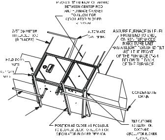
NOTE: When an existing furnace is removed from a venting system serving other appliances, the venting system may be too large to properly vent the remaining attached appliances.
The following vent testing procedure is reproduced from the
American National Standard/National Standard of Canada for Gas-Fired Central Furnaces ANSI Z21.47, latest edition, CSA-2.3b, latest edition Section 1.23.1.
The following steps shall be followed with each appliance connected to the venting system placed in operation, while any other appliances connected to the venting system are not in operation:
a.Seal any unused openings in the venting system;
b.Inspect the venting system for proper size and horizontal pitch, as required by the National Fuel Gas Code, ANSI Z223.1 or the CSA B149 Installation Codes and these instructions. Determine thatthereisnoblockageorrestriction,leakage,corrosionandother deficiencies which could cause an unsafe condition;
c.In so far as practical, close all building doors and windows and all doors between the space in which the appliance(s) connected to the venting system are located and other spaces of the building. Turn on clothes dryers and any appliance not connected to the venting system. Turn on any exhaust fans, such as range hoods and bathroom exhausts, so they shall operate at maximum speed. Do not operate a summer exhaust fan. Close fireplace dampers;
d.Follow the lighting instructions. Place the appliance being inspected in operation. Adjust thermostat so appliance shall operate continuously;
e.Test for draft hood equipped spillage at the draft hood relief opening after 5 minutes of main burner operation. Use the flame of a match or candle;
f.After it has been determined that each appliance connected to the venting system properly vents when tested as outlined above, return doors, windows, exhaust fans, fireplace dampers and any other gas burning appliance to their previous conditions of use;
g.If improper venting is observed during any of the above tests, the common venting system must be corrected.
14
INSTALLATION CONSIDERATIONS
Corrections must be in accordance with the latest edition of the National Fuel Gas Code NFPA 54/ANSI Z223.1 and/or CSA B149 Installation Codes.
If resizing is required on any portion of the venting system, use the appropriate table in Appendix G in the latest edition of the National Fuel Gas Code ANSI Z223.1 and/or CSA B149
Installation Codes.
Thermostat Requirements
A high quality single stage thermostat with a "C" terminal is recommended to control the G*SS9* and A*SS9* furnace.
Thermostat Location
In an area having good air circulation, locate the thermostat about five feet high on a vibration-free inside wall. Do not install the thermostat where it may be influenced by any of the following:
•Drafts, or dead spots behind doors, in corners, or under cabinets.
•Hot or cold air from registers.
•Radiant heat from the sun.
•Light fixtures or other appliances.
•Radiant heat from a fireplace.
•Concealed hot or cold water pipes, or chimneys.
•Unconditioned areas behind the thermostat and dehumidistat, such as an outside wall.
COMBUSTION AND VENTILATION AIR
REQUIREMENTS
 WARNING
POSSIBLE PROPERTY DAMAGE, PERSONAL INJURY OR DEATH MAY OCCUR IF THE FURNACE IS NOT PROVIDED WITH ENOUGH FRESH AIR FOR PROPER COMBUSTION AND VENTILATION OF FLUE GASES. MOST HOMES REQUIRE OUTSIDE AIR BE SUPPLIED TO THE FURNACE AREA.
Improved construction and additional insulation in buildings have reduced heat loss by reducing air infiltration and escape around doors and windows. These changes have helped in reducing heating/cooling costs but have created a problem supplying combustion and ventilation air for gas fired and other fuel burning appliances. Appliances that pull air out of the house (clothes dryers, exhaust fans, fireplaces, etc.) increase the problem by starving appliances for air.
When the furnace is installed as a direct vent (2-pipe) furnace, no special provisions for air for combustion are required. However, if this furnace is to be installed in the same space with other gas appliances, such as a water heater, ensure there is an adequate supply of combustion and ventilation air for the other appliances. Refer to the latest edition of the National Fuel Gas Code NFPA 54/ANSI Z223.1
(Section 9.3), or CAN/CGA B149 Installation Codes (Sections 7.2, 7.3, or 7.4), or applicable provisions of the local building codes for determining the combustion air requirements for the appliances.
Most homes will require outside air be supplied to the furnace area by means of ventilation grilles or ducts connecting directly to the outdoors or spaces open to the outdoors such as attics or crawl spaces.
The following information on air for combustion and ventilation is reproduced from the National Fuel Gas Code NFPA 54/ANSI
Z223.1 Section 9.3.
9.3* Air for Combustion and Ventilation.
9.3.1 General.
9.3.1.1 Air for combustion, ventilation, and dilution of flue gases for appliances installed in buildings shall be obtained by application of one of the methods covered in 9.3.2 through 9.3.6. Where the requirements of 9.3.2 are not met, outdoor air shall be introduced in accordance with methods covered in 9.3.3 through 9.3.6.
Exception No. 1: This provision shall not apply to direct vent appliances.
9.3.1.2Appliances of other than natural draft design and other than Category 1 vented appliances shall be provided with combustion, ventilation, and dilution air in accordance with the appliance manufacturer’s instructions.
9.3.1.3Appliances shall be located so as not to interfere with proper circulation of combustion, ventilation, and dilution air.
9.3.1.4Where used, a draft hood or a barometric draft regulator shall be installed in the same room or enclosure as the appliance served so as to prevent any difference in pressure between the hood or regulator and the combustion air supply.
9.3.1.5Makeup air requirements for the operation of exhaust fans, kitchen ventilation systems, clothes dryers, and fireplaces shall be considered in determining the adequacy of a space to provide combustion air requirements.
9.3.2 Indoor Combustion Air. The required volume of indoor air shall be determined in accordance with the method in 9.3.2.1 or 9.3.2.2 except that where the air infiltration rate is known to be less than 0.40 ACH, the method in 9.3.2.2 shall be used. The total required volume shall be the sum of the required volume calculated for all appliances located within the space. Rooms communicating directly with the space in which the appliances are installed through openings not furnished with doors, and through combustion air openings sized and located in accordance with 9.3.2.3, are considered a part of the required volume.
9.3.2.1* Standard Method. The minimum required volume shall be 50 ft 3 per 1,000/Btu/hour (4.8m3/kW).
9.3.2.2* Known Air Infiltration Rate Method. Where the air infiltration rate of a structure is known, the minimum required volume shall be determined as follows:
15
INSTALLATION CONSIDERATIONS
(1) For appliances other than fan-assisted, calculate using the following equation:
21 ft3 |
I |
|
Required Volume other > ________ |
|
other |
ACH |
(1000 Btu/hr) |
|
(2) For fan-assisted appliances, calculate using the following equation:
|
|
15 ft3 |
I |
|
Required Volume fan > ________ |
|
fan |
||
|
|
ACH |
(1000 Btu/hr) |
|
where: |
|
|
|
|
I other |
= |
all appliances other than fan-assisted input in Btu per |
||
|
|
hour |
|
|
I fan |
= |
fan-assisted appliances input in Btu per hour |
||
ACH |
= |
air change per hour (percent of volume of space exchanged |
||
|
|
per hour, expressed as a decimal) |
|
|
(3)For purposes of this calculation, an infiltration rate greater than 0.60 ACH shall not be used in the equations in 9.3.2.2(1) and 9.3.2.2(2).
9.3.2.3 Indoor Opening Size and Location. Openings used to connect indoor spaces shall be sized and located in accordance with the following:
(1)*Combining spaces on the same story. Each opening shall have a minimum free area of 1 in.2/1000Btu/hr (2200 mm2/kW) of the total input rating of all appliances in the space but not less than 100 in.2 (0.60m2). One opening shall commence within 12 in. (300 mm) of the top, and one opening shall commence within 12 in. (300 mm) of the bottom, of the enclosure [see Figure A.9.3.2.3(1)]. The minimum dimension of air openings shall be not less than 3 in. (80 mm).
ods in 9.3.3.1 or 9.3.3.2. The minimum dimension of air openings shall not be less than 3 in. (80 mm).
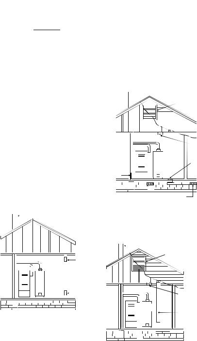
9.3.3.1 Two Permanent Openings Method. Two permanent openings, one commencing within 12 in. (300 mm) of the top and one commencing within 12 in. (300 mm) of the bottom, of the enclosure shall be provided. The openings shall communicate directly, or by ducts, with the outdoors or spaces that freely communicate with the outdoors, as follows:
(1)*Where directly communicating with the outdoors or where communicating to the outdoors through vertical ducts, each opening shall have a minimum free area of 1 in.2/4000 Btu/hr (550 min2/kW) of total input rating of all appliances in the enclosure. [See Figure
A.9.3.3.1(1)(a) and Figure A.9.3.3.1(1)(b).]
 Chimney or Gas Vent
Ventilation louvers (each end of attic)
NOTE: The inlet and outlet air openings must each have a free area of not less than one square inch per 4000 BTU of the
total input rating of all equipment in the enclosure.
|
|
|
|
|
|
Outlet Air |
|
|
|
|
|
|
|
|
|
|
|
|
|
|
|
|
|
|
|
|
Water |
|
|||
|
|
|
Heater |
|
|
|
|
|
|
|
|
|
|
||
Furnace |
Inlet Air |
||||||
|
|
|
|
||||
|
|
|
|
|
|
||
Alternate air inlet
Ventilation louvers for unheated crawl space
NOTE: Each opening must have |
|
|
Chimney or Gas Vent |
|
Figure A.9.3.3.1(1)(a) All Combustion Air From Outdoors - |
||||||||||
|
|
||||||||||||||
|
|
|
|
|
|
|
|
|
|
|
Inlet Air from Ventilated Crawl Space and Outlet Air |
||||
a free area of not less than one |
|
|
|
|
|
|
|
|
|
|
|
||||
square inch per 1000 BTU of |
|
|
|
|
|
|
|
|
|
|
|
|
|
|
to Ventilated Attic. |
the total input rating of all equip- |
|
|
|
|
|
|
|
|
|
|
|
|
|
|
|
ment in the enclosure, but not |
|
|
|
|
|
|
|
|
|
|
|
|
|
|
|
less than 100 square inches. |
|
|
|
|
|
|
|
|
|
|
|
|
Chimney or Gas Vent |
||
|
|
|
|
|
|
|
|
|
|
|
|
||||
|
|
|
|
|
|
|
|
|
|
|
|
|
|||
|
|
|
|
|
|
|
|
|
|
|
|
|
|
|
Ventilation louvers |
|
|
|
|
|
|
|
|
|
|
|
|||||
|
|
|
|
|
|
|
|
|
|
Opening |
|
|
|
|
(each end of attic) |
|
|
|
|
|
|
|
|
|
|
|
|
|
|
||
|
|
|
|
|
|
|
|
|
|
|
|
|
|
NOTE: The inlet and outlet air |
|
|
|
|
|
|
|
|
|
|
|
|
|
|
|
|
|
|
|
|
|
|
|
|
|
|
|
|
|
|
|
|
openings must each have a free |
|
|
|
|
|
|
|
|
|
|
|
|
|
|
|
area of not less than one square |
|
|
|
|
|
|
|
|
|
|
|
|
|
|
|
|
|
|
|
|
|
|
|
|
|
|
|
|||||
|
|
|
|
|
|
|
Water |
|
|
|
|||||
|
|
|
|
|
|
|
|
|
|
|
|
|
|
inch per 4000 BTU of the |
|
|
|
|
|
|
|
|
|
|
|
|
|||||
|
|
|
|
|
|
|
Heater |
|
|
|
|
|
|
||
|
|
|
Furnace |
|
|
|
|
|
|
|
|
total input rating of all equipment |
|||
|
|
|
|
|
|
|
|
|
|
|
|
|
|||
|
|
|
|
|
|
|
|
|
|||||||
|
|
|
|
|
|
|
|
|
|
|
|
|
|
|
in the enclosure. |
Opening |
|
Outlet Air |
|
|
|
|
|
Water |
|
Furnace |
Heater |
|
Inlet air duct |
|
|
|
[ends 1 ft (300 mm) |
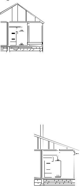
Figure A.9.2.3.3.(1) All Combustion Air from Adjacent |
|
above floor] |
|
|
|
Indoor Spaces through Indoor Combustion Air Openings. |
|
|
(2)Combining spaces in different stories. The volumes of spaces in different stories shall be considered as communicating spaces where such spaces are connected by one or more openings in doors or floors having a total minimum free area of 2 in.2/1000 Btu/hr (4400 mm2/kW) of total input rating of all appliances.
9.3.3 Outdoor Combustion Air. Outdoor combustion air shall be provided through opening(s) to the outdoors in accordance with the meth-
Figure A.9.3.3.1(1)(b) All Combustion Air
From Outdoors through Ventilated Attic.
(2)*Where communicating with the outdoors through horizontal ducts, each opening shall have a minimum free area of 1 in.2/2000 Btu/hr (1100 min2/kW) of total input rating of all appliances in the enclo-
sure. [See Figure A.9.3.3.1(2).]
16
INSTALLATION CONSIDERATIONS
 Chimney or Gas Vent
|
|
|
|
|
|
|
|
|
|
|
|
|
|
|
|
NOTE: The air duct openings |
|
|
|
|
|
|
|
|
|
|
|
|
|
|
|
|
must have a free area of not |
|
|
|
|
|
|
|
|
|
|
|
|
|
|
|
|
less than one square inch per |
|
|
|
|
|
|
|
|
|
|
|
|
|
|
|
|
2000 BTU of the total input |
|
|
|
|
|
|
|
|
|
|
|
|
|
|
|
|
rating of all equipment in the |
|
|
|
|
|
|
|
|
|
|
|
|
Outlet air duct |
|
enclosure*. |
||
|
|
|
|
|
|
|
|
|
|
|
|
|
|
|||
|
|
|
|
|
|
|
|
|
|
|
|
|
|
|
|
|
|
|
|
|
|
|
|
|
|
|
|
|
|
|
|
|
|
|
|
|
|
|
|
|
|
Water |
|
|
|
|||||
|
|
|
|
|
|
|
|
Heater |
|
|
|
|
|
|
|
|
|
|
|
|
|
|
|
|
|
|
|
|
|
|
|
|
|
|
|
|
|
Furnace |
Inlet air duct |
|
|
|||||||||
|
|
|
|
|
|
|
|
|
|
|
|
|||||
|
|
|
|
|
|
|
|
|
|
|
|
|
|
|
||
|
|
|
|
|
|
|
|
|
|
|
|
|
|
|
||
|
|
|
|
|
|
|
|
|
|
|
|
|
|
|
|
|
|
|
|
|
|
|
|
|
|
|
|
|
|
|
|
|
|
|
|
|
|
|
|
|
|
|
|
|
|
|
|
|
|
|
|
|
|
|
|
|
|
|
|
|
|
|
|
|
|
|
|
|
|
|
|
|
|
|
|
|
|
|
|
|
|
|
|
|
|
|
|
|
|
|
|
|
|
|
|
|
|
|
|
|
|
|
|
|
|
|
|
|
|
|
|
|
|
|
|
|
|
|
|
|
|
|
|
|
|
|
|
|
|
|
|
|
|
|
|
Figure A.9.3.3.1(2) All Combustion Air From Outdoors through Horizontal Ducts.
9.3.3.2* One Permanent Opening Method. One permanent openings, commencing within 12 in. (300 mm) of the top of the enclosure, shall be provided. The appliance shall have clearances of at least 1 in. (25 mm) from the sides and back and 6 in. (150 mm) from the front of the appliance. The opening shall directly communicate with the outdoors or shall communicate through a vertical or horizontal duct to the outdoors or spaces that freely communicate with the outdoors (see Figure A.9.3.3.2) and shall have a minimum free area of the following:
(1)1 in.2/3000 Btu/hr (700 mm2 per kW) of the total input rating of all appliances located in the enclosure, and
(2)Not less than the sum of the areas of all vent connectors in the space.
(c)The minimum size of outdoor opening(s) shall be the full size of outdoor opening(s) calculated in accordance with 9.3.3, multiplied by the reduction factor. The minimum dimension of air openings shall not be less than 3 in. (80 mm).
9.3.5Engineered Installations. Engineered combustion air installations shall provide an adequate supply of combustion, ventilation, and dilution air and shall be approved by the authority having jurisdiction.
9.3.6Mechanical Combustion Air Supply. Where all combustion air is provided by a mechanical air supply system, the combustion air shall be supplied form outdoors at the minimum rate of 0.35 ft3/min per 1000 Btu/hr (0.034 m3/min per kW) for all appliances located within the space.
9.3.6.1Where exhaust fans are installed, additional air shall be provided to replace the exhausted air.
9.3.6.2Each of the appliances served shall be interlocked to the mechanical air supply system to prevent main burner operation where the mechanical air supply system is not in operation.
9.3.6.3Where combustion air is provided by the building’s mechanical ventilation system, the system shall provide the specified combustion air rate in addition to the required ventilation air.
9.3.7 Louvers, Grilles, and Screens.
NOTE: The single opening must have
a free area of not less than one  Chimney or Gas Vent square inch per 3000 BTU of
the total input rating of all equip-
ment in the enclosure, but not less than the sum of the areas of all vent connectors in the confined space.
|
|
|
|
|
|
|
|
|
|
|
|
|
Opening |
|
|
|
|
|
|
|
|
|
|
|
|
|
Alternate |
|
|
|
|
|
|
|
|
|
|
|
|
||
|
|
|
|
|
|
|
|
|
|
Water |
|
||
|
|
|
|
|
|
|
|
|
|
|
|
Opening |
|
|
|
|
|
|
|
|
|
|
|
Heater |
|
||
|
|
|
|
|
|
|
|
|
|
|
Location |
||
|
|
|
|
|
Furnace |
|
|
|
|
|
|||
|
|
|
|
|
|
|
|
|
|||||
|
|
|
|
|
|
|
|
|
|
|
|
|
|
|
|
|
|
|
|
|
|
|
|
|
|
|
|
|
|
|
|
|
|
|
|
|
|
|
|
|
|
|
|
|
|
|
|
|
|
|
|
|
|
|
|
|
|
|
|
|
|
|
|
|
|
|
|
|
|
|
|
|
|
|
|
|
|
|
|
|
|
|
|
Figure A.9.3.3.2 All Combustion Air
From Outdoors through Single Combustion Air Opening.
9.3.4 Combination Indoor and Outdoor Combustion Air. The use of a combination of indoor and outdoor combustion air shall be in accordance with (1) through (3) (see example calculation in Annex J]:
(1)Indoor Openings: Where used, openings connecting the interior spaces shall comply with 9.3.2.3.
(2)Outdoor Opening(s) Location. Outdoor opening(s) shall be located in accordance with 9.3.3.
(3)Outdoor Opening(s) Size. The outdoor opening(s) size shall be calculated in accordance with the following:
(a)The ratio of the interior spaces shall be the available volume of all communicating spaces divided by the required volume.
(b)The outdoor size reduction factor shall be 1 minus the ratio of interior spaces.
9.3.7.1Louvers and Grilles. The required size of openings for combustion, ventilation, and dilution air shall be based on the net free area of each opening. Where the free area through a design of louver or grille or screen is known, it shall be used in calculating the size opening required to provide the free area specified. Where the louver and grille design and free area are not known, it shall be assumed that wood louvers will have 25 percent free area, and metal louvers and grilles will have 75 percent free area. Nonmotorized louvers and grilles shall be fixed in the open position.
9.3.7.2Minimum Scree Mesh Size. Screens shall not be smaller than 1/4 in. mesh.
9.3.7.3Motorized Louvers. Motorized louvers shall be interlocked with the appliance so they are proven in the full open position prior to main burner ignition and during main burner operation. Means shall be provided to prevent the main burner form igniting should the louver fail to open during burner startup and to shut down the main burner if the louvers close during burner operation.
9.3.8 Combustion Air Ducts. Combustion air ducts shall comply with 9.3.8.1 through 9.3.8.8.
9.3.8.1 Ducts shall be constructed of galvanized steel or a material having equivalent corrosion resistance, strength, and rigidity.
Exception: Within dwellings units, unobstructed stud and joist spaces shall not be prohibited from conveying combustion air, provided that not more than one fireblock is removed.
9.3.8.2Ducts shall terminate in an unobstructed space, allowing free movement of combustion air to the appliances.
9.3.8.3Ducts shall serve a single space.
17
INSTALLATION CONSIDERATIONS
9.3.8.4Ducts shall not serve both upper and lower combustion air openings where both such openings are used. The separation between ducts servicing upper and lower combustion air openings shall be maintained to the source of combustion air.
9.3.8.5Ducts shall not be screened where terminating in an attic space.
9.3.8.6Horizontal upper combustion air ducts shall not slope downward toward the source of combustion air.
9.3.8.7The remaining space surrounding a chimney liner, gas vent, special gas vent, or plastic piping installed within a masonry, metal, or factory built chimney shall not be used to supply combustion air.
Exception: Direct vent appliances designed for installation in a solid fuel-burning fireplace where installed in accordance with the manufacture’s installation instructions.
9.3.8.8 Combustion air intake openings located on the exterior of the building shall have the lowest side of the combustion air intake openings located at least 12 in. (300 mm) vertically from the adjoining grade level.
Horizontal Applications and Considerations
Horizontal applications, in particular, may dictate many of the installation’s specifics such as airflow direction, ductwork connections, flue and/or combustion air pipe connections, etc. The basic application of this furnace as a horizontal furnace differs only slightly from an upright installation. When installing a furnace horizontally, additional consideration must be given to the following:
Drain Trap and Lines
In horizontal applications the condensate drain trap is secured to the furnace side panel, suspending it below the furnace. A minimum clearance of 5.5" below the furnace must be provided for the drain trap. Additionally, the appropriate downward piping slope must be maintained from the drain trap to the drain location. Refer to Condensate Drain Trap and Lines section in this manual or the installation instructions for further details. If the drain trap and drain line will be exposed to temperatures near or below freezing, adequate measures must be taken to prevent condensate from freezing. NOTE: The use of insulation and/or heat tape is recommended. Failure to provide proper condensate drainage can result in property damage.
Leveling
Leveling ensures proper condensate drainage from the heat exchanger and induced draft blower. For proper flue pipe drainage, the furnace must be level lengthwise from end to end. The furnace should also be level from back to front or have a slight tilt with the access doors downhill (approximately 3/4") from the back panel. The slight tilt allows the heat exchanger condensate, generated in the recuperator coil, to flow forward to the recuperator coil front cover.
In horizontal installations with the furnace laying on the left hand side, the alternate vent connection may be used. In this configuration the internal elbow is removed. The standard piping connections may also be used in these posi-
tions. Refer to Vent/Flue Pipe and Combustion Air Pipe section in the installation instructions for details concerning the conversion to the alternate vent/flue and combustion air connections on the 90% furnace.
The 34.5" single stage furnace is one of the products in our newly redesigned line of shorter chassis furnaces. It is available in 92% / 96% AFUE up flow / horizontal model and a down flow / horizontal model.
The up flow / horizontal 34.5" single stage furnace is available in the following models:
*MSS920402BNAA
*MSS920603BNAA
*MSS9S0803BNAA
*MSS920804CNAA
*MSS920805CNAA
*MSS921004CNAA
*MSS921005CNAA
*MSS921205DNAA
*MSS960402BNAA
*MSS960603BNAA
*MSS960803BNAA
*MSS960804CNAA
*MSS960805CNAA
*MSS961005CNAA
*MSS961205DNAA
The down flow / horizontal 34.5" single stage furnace is available in the following models.
*CSS920402BNAA
*CSS920603BNAA
*CSS920804CNAA
*CSS921005CNAA
*CSS960402BNAA
*CSS960603BNAA
*CSS960804CNAA
*CSS961005CNAA
*CSS961205CNAA
18
 Loading...