


INSTALLATION INSTRUCTIONS FOR
COMMERCIAL HEATING & COOLING
7.5 TON - 12.5 TON PACKAGE GAS SERIES
CPG SERIES
®
C |
US |
|
|
|
|
This Forced Air Central Unit Design Complies With
Requirements Embodied in The American National
Standard / National Standard of Canada Shown
Below.
ANSI Z21.47•CSA-2.3 Central Furnaces
 RECOGNIZE THIS SYMBOL AS A SAFETY PRECAUTION.
ATTENTION INSTALLING PERSONNEL
Prior to installation, thoroughly familiarize yourself with this Installation Manual. Observe all safety warnings. During installation or repair, caution is to be observed.
It is your responsibility to install the product safely and to educate the customer on its safe use.
|
*NOTE: Please contact your distributor or our website |
|
|
|
|
|
|
|
|
|
|
|||
|
for the applicable Specification Sheet referred to in this manual. |
|
|
|
|
|
|
|
|
|
|
|||
|
All information contained herein is subject to change without notice. |
|
|
|
|
|
|
|
|
|
|
|||
IO-337J |
© 2008 |
- 2010 Goodman Manufacturing Company, L.P. |
|
|
|
|
|
|
|
|
|
|
|
|
6/10 |
5151 |
San Felipe, Suite 500 |
◊ Houston, TX 77056 |
|
|
|
|
|
|
|
|
|
|
|
|
www.goodmanmfg.com |
www.amana-hac.com |
|
|
|
|
|
|
|
|
|
|
|
|
Index |
|
Replacement Parts ........................................................ |
2 |
Safety Instructions ........................................................ |
2 |
General Information ...................................................... |
3 |
Unit Location ................................................................. |
4 |
Clearances ..................................................................... |
6 |
Roof Curb Post-Installation .......................................... |
6 |
Checks ........................................................................... |
6 |
Roof Top Duct Connections ......................................... |
6 |
Rigging Details .............................................................. |
7 |
Electrical Wiring ............................................................ |
8 |
Gas Supply Piping ....................................................... |
10 |
Propane Gas Installations .......................................... |
12 |
Circulating Air and Filters ........................................... |
13 |
Venting ......................................................................... |
13 |
Condensate Drain Connection ................................... |
13 |
Startup, Adjustments, and Checks ............................ |
13 |
Normal Sequence Of Operation ................................. |
19 |
Troubleshooting .......................................................... |
20 |
Input Rating ................................................................. |
21 |
Air flow Adjustments................................................... |
21 |
Motor Sheave Adjustments ........................................ |
21 |
Maintenance ................................................................ |
22 |
Appendix A Blower Performance Data ...................... |
24 |
Belt Drive - STANDARD hORIZONTAL ....................... |
24 |
Appendix A Blower Performance Data ...................... |
25 |
Belt Drive - STANDARD dOWN sHOT ........................ |
25 |
Belt Drive - HIGH STATIC (“AA” Models Only) .......... |
26 |
Appendix B Electrical Data ......................................... |
27 |
Appendix C Unit Dimensions ..................................... |
28 |
Wiring Diagrams .......................................................... |
29 |
 WARNING
SHOULD OVERHEATING OCCUR OR THE GAS SUPPLY FAIL TO SHUT OFF,
TURN OFF THE MANUAL GAS SHUTOFF VALVE EXTERNAL TO THE FURNACE BEFORE TURNING OFF THE ELECTRICAL SUPPLY.
 CAUTION
SHEET METAL PARTS, SCREWS, CLIPS AND SIMILAR ITEMS INHERENTLY HAVE SHARP EDGES, AND IT IS NECESSARY THAT THE INSTALLER AND SERVICE PERSONNEL EXERCISE CAUTION.
REPLACEMENT PARTS
ORDERING PARTS
When reporting shortages or damages, or ordering repair parts, give the complete unit model and serial numbers as stamped on the unit’s nameplate.
Replacement parts for this appliance are available through your contractor or local distributor. For the location of your nearest distributor, consult the white business pages, the yellow page section of the local telephone book or contact:
CONSUMER AFFAIRS
GOODMAN MANUFACTURING COMPANY, L.P.
7401 SECURITY WAY
HOUSTON, TEXAS 77040 877-254-4729
SAFETY INSTRUCTIONS
TO THE INSTALLER
Before installing this unit, please read this manual to familiarize yourself on the specific items which must be adhered to, including maximum external static pressure to unit, air temperature rise, minimum or maximum CFM and motor speed connections.
Keep this literature in a safe place for future reference.
 WARNING
IF THE INFORMATION IN THESE INSTRUCTIONS IS NOT FOLLOWED EXACTLY, A FIRE OR EXPLOSION MAY RESULT CAUSING PROPERTY DAMAGE, PERSONAL INJURY OR LOSS OF LIFE.
DO NOT STORE OR USE GASOLINE OR OTHER FLAMMABLE VAPORS AND LIQUIDS IN THE VICINITY OF THIS OR ANY OTHER APPLIANCE.
WHAT TO DO IF YOU SMELL GAS:
DO NOT TRY TO LIGHT ANY APPLIANCE.
DO NOT TOUCH ANY ELECTRICAL SWITCH; DO NOT USE ANY PHONE IN YOUR BUILDING.
IMMEDIATELY CALL YOUR GAS SUPPLIER FROM A NEIGHBOR’S PHONE. FOLLOW THE GAS SUPPLIER’S INSTRUCTIONS.
IF YOU CANNOT REACH YOUR GAS SUPPLIER, CALL THE FIRE DEPARTMENT.
INSTALLATION AND SERVICE MUST BE PERFORMED BY A QUALIFIED INSTALLER, SERVICE AGENCY OR THE GAS SUPPLIER.
 WARNING
DO NOT CONNECT TO OR USE ANY DEVICE THAT IS NOT DESIGN CERTIFIED BY GOODMAN FOR USE WITH THIS UNIT. SERIOUS PROPERTY DAMAGE, PERSONAL INJURY, REDUCED UNIT PERFORMANCE AND/OR HAZARDOUS CONDITIONS MAY RESULT FROM THE USE OF SUCH NON APPROVED DEVICES.
2

 WARNING
THIS PRODUCT CONTAINS OR PRODUCES A CHEMICAL OR CHEMICALS WHICH MAY CAUSE SERIOUS ILLNESS OR DEATH AND WHICH ARE KNOWN TO THE STATE OF CALIFORNIA TO CAUSE CANCER, BIRTH DEFECTS OR OTHER REPRODUCTIVE HARM.
 WARNING
TO AVOID PROPERTY DAMAGE, PERSONAL INJURY OR DEATH, DO NOT USE THIS UNIT IF ANY PART HAS BEEN UNDER WATER. IMMEDIATELY CALL A QUALIFIED SERVICE TECHNICIAN TO INSPECT THE FURNACE AND TO REPLACE ANY PART OF THE CONTROL SYSTEM AND ANY GAS CONTROL HAVING BEEN UNDER WATER.
 WARNING
THIS UNIT MUST NOT BE USED AS A “CONSTRUCTION HEATER” DURING THE FINISHING PHASES OF CONSTRUCTION ON A NEW STRUCTURE. THIS TYPE OF USE MAY RESULT IN PREMATURE FAILURE OF THE UNIT DUE TO EXTREMELY LOW RETURN AIR TEMPERATURES AND EXPOSURE TO CORROSIVE OR VERY DIRTY ATMOSPHERES.
 WARNING
HIGH VOLTAGE !
DISCONNECT ALL POWER BEFORE SERVICING OR
INSTALLING THIS UNIT. MULTIPLE POWER SOURCES MAY
BE PRESENT. FAILURE TO DO SO MAY CAUSE PROPERTY
DAMAGE, PERSONAL INJURY OR DEATH.
 WARNING
TO PREVENT THE RISK OF PROPERTY DAMAGE, PERSONAL INJURY OR DEATH, DO NOT STORE COMBUSTIBLE MATERIALS OR USE GASOLINE OR OTHER FLAMMABLE LIQUIDS OR VAPORS IN THE VICINITY OF THIS APPLIANCE.
 WARNING
ONLY INDIVIDUALS MEETING (AT A MINIMUM) THE REQUIREMENTS OF AN “ENTRY LEVEL TECHNICIAN” AS SPECIFIED BY THE AIR
CONDITIONING, HEATING, AND REFRIGERATION INSTITUTE (AHRI)
MAY USE THIS INFORMATION. ATTEMPTING TO INSTALL OR REPAIR THIS UNIT WITHOUT SUCH BACKGROUND MAY RESULT IN PRODUCT DAMAGE, PERSONAL INJURY OR DEATH.
WARNING
CARBON MONOXIDE POISONING
HAZARD
FAILURE TO KEEP THIS COMPARTMENT CLOSED
EXCEPT WHEN SERVICING COULD RESULT IN
CARBON MONOXIDE POISONING OR DEATH.
THIS COMPARMENT MUST BE CLOSED EXCEPT
WHEN SERVICING
 AVERTISSEMENT
RISQUE D'EMPOISONNEMENT AU
MONOXYDE DE CARBONE
SI CE COMPARTMENT N'EST PAS FERME EN
TOUT TEMPS, SAUF EN CAS DE REPARATION, IL Y
A RISQUE D'EMPOISONNEMENT OU MONOXYDE
DE CARBONE OU DE MORT.
CE COMPARTIMENT DOIT ETRE FERME SAUF AU
MOMENT DE L'ENTRETIEN.
ADVERTENCIA
PELIGRO MONOXIDO DE CARBONO
TOXICO
EL FRACASO DE NO MANTENER
COMPARTIMIENTO CERRADO MENOS DURANTE,
ATENDER, PODRIA TENER COMO RESULTADO
ENVENENAR DE MONOXIDO DE CARBONO O
MUERTE.
ESTE COMPARTIMIENTO DEBE CERRADO MENOS
AL ATENDER |
- |
0140L00106 |
GENERAL INFORMATION
 WARNING
TO PREVENT PROPERTY DAMAGE, PERSONAL INJURY OR DEATH DUE TO FIRE, EXPLOSIONS, SMOKE, SOOT, CONDENSATION, ELECTRIC SHOCK OR CARBON MONOXIDE, THIS UNIT MUST BE PROPERLY INSTALLED,
REPAIRED, OPERATED AND MAINTAINED.
This unit is approved for outdoor installation ONLY. To assure that your unit operates safely and efficiently, it must be installed, operated, and maintained in accordance with these installation and operating instructions, all local building codes and ordinances, or in their absence, with the latest edition of the National Fuel Gas Code NFPA54/ANSI Z223.1 and National Standard of Canada CAN/CSA B149 Installation Codes.
The heating and cooling capacities of the unit should be greater than or equal to the design heating and cooling loads of the area to be conditioned. The loads should be calculated by an approved method or in accordance with ASHRAE Guide or Manual J - Load Calculations published by the Air Conditioning Contractors of America.
Obtain from:
American National Standards Institute
1430 Broadway
New York, NY 10018
3

System design and installation should also, where applicable, follow information presented in accepted industry guides such as the ASHRAE Handbooks. The manufacturer assumes no responsibility for equipment installed in violation of any code or regulation. The mechanical installation of the packaged roof top units consists of making final connections between the unit and building services; supply and return duct connections; and drain connections (if required). The internal systems of the unit are completely factory-installed and tested prior to shipment.
Units are generally installed on a steel roof mounting curb assembly which has been shipped to the job site for installation on the roof structure prior to the arrival of the unit. The model number shown on the unit’s identification plate identifies the various components of the unit such as refrigeration tonnage, heating input and voltage.
Carefully inspect the unit for damage including damage to the cabinetry. Any bolts or screws which may have loosened in transit must be re-tightened. In the event of damage, the receiver should:
1.Make notation on delivery receipt of any visible damage to shipment or container.
2.Notify carrier promptly and request an inspection.
3.In case of concealed damage, carrier should be notified as soon as possible-preferably within 5 days.
4.File the claim with the following supporting documents:
a.Original Bill of Lading, certified copy, or indemnity bond.
b.Original paid freight bill or indemnity in lieu thereof.
c.Original invoice or certified copy thereof, showing trade and other discounts or reductions.
d.Copy of the inspection report issued by carrier representative at the time damage is reported to the carrier. The carrier is responsible for making prompt inspection of damage and for a thorough investigation of each claim. The distributor or manufacturer will not accept claims from dealers for transportation damage.
NOTE: When inspecting the unit for transportation damage, remove all packaging materials. Recycle or dispose of the packaging material according to local codes.
PRE-INSTALLATION CHECKS
Carefully read all instructions for the installation prior to installing unit. Ensure each step or procedure is understood and any special considerations are taken into account before starting installation. Assemble all tools, hardware and supplies needed to complete the installation. Some items may need to be purchased locally.
UNIT LOCATION
 WARNING
TO PREVENT POSSIBLE EQUIPMENT DAMAGE, PROPERTY DAMAGE,
PERSONAL INJURY OR DEATH, THE FOLLOWING BULLET POINTS MUST BE OBSERVED WHEN INSTALLING THE UNIT.
IMPORTANT NOTE: Remove wood shipping rails and metal shipping brace (if applicable) prior to installation of the unit on a roof curb.
ALL INSTALLATIONS:
NOTE: Appliance is shipped from factory for vertical duct application.
Proper installation of the unit ensures trouble-free operation. Improper installation can result in problems ranging from noisy operation to property or equipment damages, dangerous conditions that could result in injury or personal property damage and could void the warranty. Give this booklet to the user and explain it’s provisions. The user should retain these instructions for future reference.
•For proper flame pattern within the heat exchanger and proper condensate drainage, the unit must be mounted level.
•The flue outlet must be at least 12 inches from any opening through which flue gases could enter a building, and at least three feet above any forced air inlet located within ten feet. The economizer/manual fresh air intake/motorized fresh air intake and combustion air inlet mounted on the unit are not affected by this restriction.
•To avoid possible corrosion of the heat exchanger, do not locate the unit in an area where the outdoor air (i.e. combustion air for the unit) will be frequently contaminated by compounds containing chlorine or fluorine. Common sources of such compounds include swimming pool chemicals and chlorine bleaches, paint stripper, adhesives, paints, varnishes, sealers, waxes (which are not yet dried) and solvents used during construction and remodeling. Various commercial and industrial processes may also be sources of chlorine/ fluorine compounds.
•To avoid possible illness or death of the building occupants, do NOT locate outside air intake device (economizer, manual fresh air intake, motorized fresh air intake) too close to an exhaust outlet, gas vent termination, or plumbing vent outlet. For specific distances required, consult local codes.
•Allow minimum clearances from the enclosure for fire protection, proper operation, and service access (see unit clearances). These clearances must be permanently maintained.
•The combustion air inlet and flue outlet on the unit must never be obstructed. If used, do not allow the economizer/manual fresh air damper/ motorized fresh air damper to become blocked by snow or debris. In some climates or locations, it may be necessary to elevate the unit to avoid these problems.
•When the unit is heating, the temperature of the return air entering the unit must be between 50° F and 100° F.
4

GROUND LEVEL INSTALLATIONS ONLY:
•When the unit is installed on the ground adjacent to the building, a level concrete (or equal) base is recommended. Prepare a base that is 3” larger than the package unit footprint and a minimum of 3” thick.
•The base should also be located where no runoff of water from higher ground can collect in the unit.
ROOF TOP INSTALLATIONS ONLY:
•To avoid possible property damage or personal injury, the roof must have sufficient structural strength to carry the weight of the unit(s) and snow or water loads as required by local codes. Consult a structural engineer to determine the weight capabilities of the roof.
•The unit may be installed directly on wood floors or on Class A, Class B, or Class C roof covering material.
•To avoid possible personal injury, a safe, flat surface for service personnel should be provided.
•As indicated on the unit data plate, a minimum clearance of 36” to any combustible material is required on the furnace access side of the unit. All combustible materials must be kept out of this area.
•This 36” clearance must also be maintained to insure proper combustion air and flue gas flow. The combustion air intake and furnace flue discharge must not be blocked for any reason, including blockage by snow.
•Adequate clearances from the furnace flue discharge to any adjacent public walkways, adjacent buildings, building openings or openable windows must be maintained in accordance with the latest edition of the National Fuel Gas Code (ANSI Z223.1)
•Minimum horizontal clearance of 48” from the furnace flue discharge to any electric meters, gas meters, regulators and relief equipment is required.
UNIT PRECAUTIONS
•Do not stand or walk on the unit.
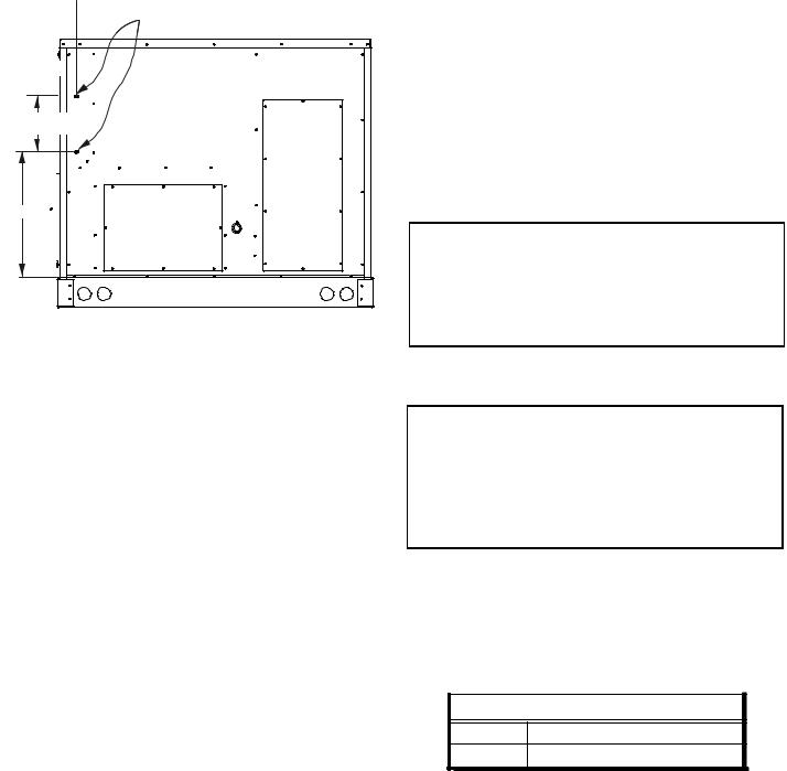
•Except for holes in the wiring entrances (see Figure below), do not drill holes anywhere in panels or in the base frame of the unit. Unit access panels provide structural support.

 3 3/4” DIMPLES MARK DRILL LOCATIONS
HIGH VOLTAGE ENTRANCE |
10 3/16” |
LOW VOLTAGE ENTRANCE |
26 ½” |
ELECTRICAL ENTRANCE LOCATIONS
•Do not remove any access panels until unit has been installed on roof curb or field supplied structure.
•Do not roll unit across finished roof without prior approval of owner or architect.
•Do not skid or slide on any surface as this may damage unit base. The unit must be stored on a flat, level surface. Protect the condenser coil because it is easily damaged.
ROOF CURB INSTALLATIONS ONLY:
Curb installations must comply with local codes and should be done in accordance with the established guidelines of the National Roofing Contractors Association.
Proper unit installation requires that the roof curb be firmly and permanently attached to the roof structure. Check for adequate fastening method prior to setting the unit on the curb.
Full perimeter roof curbs are available from the factory and are shipped unassembled. Field assembly, squaring, leveling and mounting on the roof structure are the responsibility of the installing contractor. All required hardware necessary for the assembly of the sheet metal curb is included in the curb accessory.
 WARNING
TO PREVENT POSSIBLE EQUIPMENT DAMAGE, PROPERTY DAMAGE,
PERSONAL INJURY OR DEATH, THE FOLLOWING BULLET POINTS MUST BE OBSERVED WHEN INSTALLING THE UNIT.
•Sufficient structural support must be determined prior to locating and mounting the curb and package unit.
•Ductwork must be constructed using industry guidelines. The duct work must be placed into the roof curb before mounting the package unit. Our full perimeter curbs include duct connection frames to be assembled with the curb. Cantilevered type curbs are not available from the factory.
5
• Curb insulation, cant strips, flashing and general roofing material are furnished by the contractor.
The curbs must be supported on parallel sides by roof members. The roof members must not penetrate supply and return duct opening areas as damage to the unit might occur.
NOTE: The unit and curb accessories are designed to allow vertical duct installation before unit placement. Duct installation after unit placement is not recommended.
 CAUTION
ALL CURBS LOOK SIMILAR. TO AVOID INCORRECT CURB POSITIONING,
CHECK JOB PLANS CAREFULLY AND VERIFY MARKINGS ON CURB ASSEMBLY. INSTRUCTIONS MAY VARY IN CURB STYLES AND SUPERCEDE INFORMATION SHOWN.
See the manual shipped with the roof curb for assembly and installation instructions.
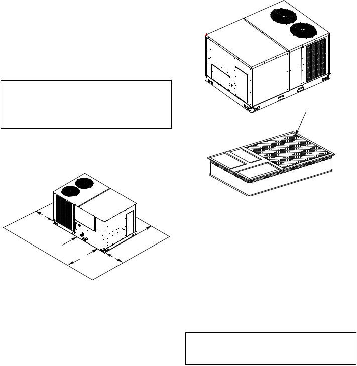
CLEARANCES
48”


 48”
48”  36” MIN.


75” 6”
UNIT CLEARANCES
Adequate clearance around the unit should be kept for safety, service, maintenance, and proper unit operation. A total clearance of 75” on the main control panel side of the unit is recommended to facilitate possible fan shaft, coil, electric heat and gas furnace removal. A clearance of 48” is recommended on all other sides of the unit to facilitate possible compressor removal, to allow service access and to insure proper ventilation and condenser airflow. The unit must not be installed beneath any obstruction. The unit should be installed remote from all building exhausts to inhibit ingestion of exhaust air into the unit fresh air intake.
INSULATED
PANELS
ROOF CURB INSTALLATION
ROOF CURB POST-INSTALLATION
CHECKS
After installation, check the top of the curb, duct connection frame and duct flanges to make sure gasket has been applied properly. Gasket should be firmly applied to the top of the curb perimeter, duct flanges and any exposed duct connection frame. If gasket is loose, re-apply using strong weather resistant adhesive.
PROTRUSION
Inspect curb to ensure that none of the utility services (electric) routed through the curb protrude above the curb.
 CAUTION
IF PROTRUSIONS EXIST, DO NOT ATTEMPT TO SET UNIT ON CURB. INFORMATION SHOWN.
ROOF TOP DUCT CONNECTIONS
Install all duct connections on the unit before placing the unit on rooftop.
HORIZONTAL DISCHARGE
For horizontal discharge, remove the supply and return duct covers and place them over the vertical discharge return and supply openings. Install with insulation facing up, using the longer screws provided in the literature package.
6
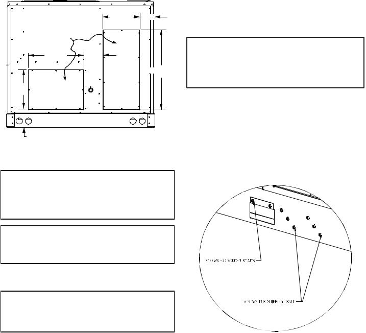
Ensure that the top of the duct connection frame is flush with the top of the roof curb.
Flexible duct connectors between the unit and ducts are recommended. Insulate and weatherproof all external ductwork and joints as required and in accordance with local codes.
|
|
12 5/8” |
5 7/8” |
|
REMOVE |
|
|
|
COVERS |
|
|
|
28 3/8” |
7 3/8” |
|
|
|
RETURN |
36 3/8” |
13 7/8” |
SUPPLY |
|
|
6 1/4” |
|
|
|
HORIZONTAL DISCHARGE DUCT CONNECTIONS
RIGGING DETAILS
 WARNING
TO PREVENT PROPERTY DAMAGE, THE UNIT SHOULD REMAIN IN AN UPRIGHT POSITION DURING ALL RIGGING AND MOVING OPERATIONS. TO FACILITATE LIFTING AND MOVING WHEN A CRANE IS USED, PLACE THE UNIT IN AN ADEQUATE CABLE SLING.
 CAUTION
DO NOT LIFT UNITS TWO AT A TIME. PROVISIONS FOR FORKS HAVE BEEN INCLUDED IN THE UNIT BASE FRAME. MINIMUM FORK LENGTH IS 48” TO PREVENT DAMAGE TO THE UNIT.
Provisions for forks have been included in the unit base frame. No other fork locations are approved.
 WARNING
TO PREVENT POSSIBLE EQUIPMENT DAMAGE, PROPERTY DAMAGE,
PERSONAL INJURY OR DEATH, THE FOLLOWING BULLET POINTS MUST BE OBSERVED WHEN INSTALLING THE UNIT.
•Unit must be lifted by the four lifting holes located at the base frame corners.
•Lifting cables should be attached to the unit with shackles.
•The distance between the crane hook and the top of the unit must not be less than 60”.
•Two spreader bars must span over the unit to prevent damage to the cabinet by the lift cables. Spreader bars must be of sufficient length so that cables do not come in contact with the unit during transport.
Remove wood struts mounted beneath unit base frame before setting unit on roof curb. These struts are intended to protect unit base frame from fork lift damage. Removal is accomplished by extracting the sheet metal retainers and pulling the struts through the base of the unit. Refer to rigging label on the unit.
•Your unit may be equipped with a steel shipping brace located underneath the unit (under compressors). If installing on a roof curb, the brace MUST be removed. Follow the following instructions for removal.
 CAUTION
WHEN UNIT IS SUSPENDED, BOARDS AND SHIPPING BRACE WILL DROP WHEN SCREWS ARE REMOVED. TO PREVENT PERSONAL INJURY, STAND CLEAR. REMOVE FORK HOLE BRACKETS, BOARDS AND SHIPPING BRACE FROM BOTTOM OF UNIT BEFORE PLACING UNIT ONTO CURB.
Before installing this unit on a roof curb:
1.Remove wooden struts per installation instructions.
These are the struts that are located in the fork holes and are used to protect the unit from damage while lifting with forks.
2.Locate and remove the twelve (12) screws that attach the shipping brace to the side rails. There will be six
(6) screws on each side of the unit and they are in a diagonal pattern. See following figure.
3.Lift unit per the “Rigging Details” section of the installation instructions, observing all warnings and cautions. Lift the unit high enough off the ground to reach under and grasp the shipping brace.
4.Rotate the brace by tapping the ends until the brace falls free from the unit.
5.Dispose of the brace appropriately.
7

Important: If using bottom discharge with roof curb, ductwork should be attached to the curb prior to installing the unit. Ductwork dimensions are shown in Roof Curb Installation Instructions.
Refer to the Roof Curb Installation Instructions for proper curb installation. Curbing must be installed in compliance with the National Roofing Contractors Association Manual.
Lower unit carefully onto roof mounting curb. While rigging unit, center of gravity will cause condenser end to be lower than supply air end.
DATA |
CPG Weights (lbs) |
|
||
090/102 |
120 |
|
150 |
|
|
|
|||
|
|
|
|
|
Corner Weight - A |
195 |
230 |
|
335 |
|
|
|
|
|
Corner Weight - B |
270 |
330 |
|
390 |
|
|
|
|
|
Corner Weight - C |
240 |
280 |
|
295 |
|
|
|
|
|
Corner Weight - D |
330 |
405 |
|
345 |
Unit Shipping Weight |
1055 |
1275 |
|
1390 |
|
|
|
|
|
Unit Operating Weight |
1030 |
1235 |
|
1365 |
|
|
|
|
|
X (Inches) |
55 |
55 |
|
47 |
Y (Inches) |
36 |
36 |
|
33.5 |
To assist in determining rigging requirements, unit weights are shown as follows:
|
A |
C |
Y |
|
RETURN |
|
COMPRESSOR 1 |
EVAPORATOR COIL |
|
|
|
|
COMPRESSOR 2 |
CG |
|
|
|
|
|
SUPPLY |
B |
X |
D |
CORNER & CENTER OF GRAVITY LOCATIONS
 CAUTION
TO PREVENT SEVERE DAMAGE TO THE BOTTOM OF THE UNIT, DO NOT FORK LIFT UNIT AFTER WOOD STRUTS HAVE BEEN REMOVED.
Bring condenser end of unit into alignment with the curb. With condenser end of the unit resting on curb member and using curb as a fulcrum, lower opposite end of the unit until entire unit is seated on the curb. When a rectangular cantilever curb is used, care should be taken to center the unit. Check for proper alignment and orientation of supply and return openings with duct.
RIGGING REMOVAL
 CAUTION
TO PREVENT DAMAGE TO THE UNIT, DO NOT ALLOW CRANE HOOKS AND SPREADER BARS TO REST ON THE ROOF OF THE UNIT.
Remove spreader bars, lifting cables and other rigging equipment.
ELECTRICAL WIRING
 WARNING
HIGH VOLTAGE !
DISCONNECT ALL POWER BEFORE SERVICING OR
INSTALLING THIS UNIT. MULTIPLE POWER SOURCES MAY
BE PRESENT. FAILURE TO DO SO MAY CAUSE PROPERTY
DAMAGE, PERSONAL INJURY OR DEATH.
 WARNING
HIGH VOLTAGE !
TO AVOID PERSONAL INJURY OR DEATH DUE TO ELECTRICAL SHOCK, DO NOT TAMPER WITH FACTORY WIRING. THE INTERNAL POWER AND CONTROL WIRING OF THESE UNITS ARE FACTORY INSTALLED AND HAVE BEEN THOROUGHLY TEST PRIOR TO SHIPMENT. CONTACT YOUR LOCAL REPRESENTATIVE IF ASSISTANCE IS REQUIRED.
 CAUTION
TO PREVENT DAMAGE TO THE WIRING, PROTECT WIRING FROM SHARP EDGES. FOLLOW NATIONAL ELECTRICAL CODE AND ALL LOCAL CODES AND ORDINANCES. DO NOT ROUTE WIRES THROUGH REMOVABLE ACCESS PANELS.
8
 CAUTION
CONDUIT AND FITTINGS MUST BE WEATHER TIGHT TO PREVENT WATER ENTRY INTO THE BUILDING.
For unit protection, use a fuse or HACR circuit breaker that is in excess of the circuit ampacity, but less than or equal to the maximum overcurrent protection device. DO NOT EXCEED THE MAXIMUM OVERCURRENT DEVICE SIZE SHOWN ON UNIT DATA PLATE.
All line voltage connections must be made through weatherproof fittings. All exterior power supply and ground wiring must be in approved weatherproof conduit.
The main power supply wiring to the unit and low voltage wiring to accessory controls must be done in accordance with these instructions, the latest edition of the National Electrical Code (ANSI/NFPA 70), and all local codes and ordinances. All field wiring shall conform with the temperature limitations for Type T wire (63°F/35°C rise).
The main power supply shall be three-phase, three wire. The unit is factory wired for the voltage shown on the unit’s data plate.
NOTE: If supply voltage is 208V, all leads on primary of transformer TRANS1 must be moved from the 230V to the 208V tap.
Main power wiring should be sized for the minimum wire ampacity shown on the unit’s database. Size wires in accordance with the ampacity tables in Article 310 of the National Electrical Code. If long wires are required, it may be necessary to increase the wire size to prevent excessive voltage drop. Wires should be sized for a maximum of 3% voltage drop.
 CAUTION
TO AVOID PROPERTY DAMAGE OR PERSONAL INJURY DUE TO FIRE, USE ONLY COPPER CONDUCTORS.
 CAUTION
TO PREVENT IMPROPER AND DANGEROUS OPERATION DUE TO WIRING ERRORS, LABEL ALL WIRES PRIOR TO DISCONNECTION WHEN SERVICING CONTROLS. VERIFY PROPER OPERATION AFTER SERVICING.
NOTE: A weather-tight disconnect switch, properly sized for the unit total load, must be field installed. An external field supplied disconnect may be mounted on the exterior panel.
Ensure the data plate is not covered by the field-supplied disconnect switch.
•Some disconnect switches are not fused. Protect the power leads at the point of distribution in accordance with the unit data plate.
•The unit must be electrically grounded in accordance with local codes or, in the absence of local codes, with the latest edition of the National Electrical Code
(ANSI-NFPA 70). A ground lug is provided for this purpose. Size grounding conductor in accordance with Table 250-95 of the National Electrical Code. Do not use the ground lug for connecting a neutral conductor.
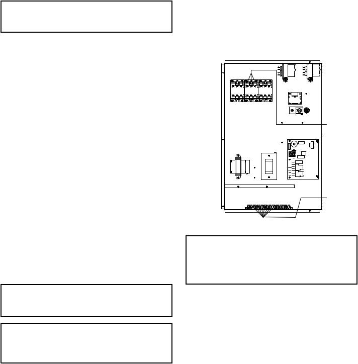
•Connect power wiring to the middle contactor within the main control box.
FAN |
RCCF |
FAN |
RCCF |
C |
|
C |
|
|
6 |
4 |
|
|
|
2 |
|
|
3 |
1 |
|
|
|
|
POWER |
|
|
|
WIRING |
|
|
|
THERMOSTAT |
|
|
|
WIRING |
POWER AND LOW VOLTAGE BLOCK LOCATIONS
 WARNING
FAILURE OF UNIT DUE TO OPERATION ON IMPROPER LINE VOLTAGE OR WITH EXCESSIVE PHASE UNBALANCE CONSTITUTES PRODUCT ABUSE AND WILL VOID YOUR WARRANTY AND MAY CAUSE SEVERE DAMAGE TO THE UNIT ELECTRICAL COMPONENTS.
AREAS WITHOUT CONVENIENCE OUTLET
It is recommended that an independent 115V power source be brought to the vicinity of the roof top unit for portable lights and tools used by the service mechanic.
UNITS INSTALLED ON ROOF TOPS
Main power and low voltage wiring may enter the unit through the side or through the roof curb. Install conduit connectors at the desired entrance locations. External connectors must be weatherproof. All holes in the unit base must be sealed (including those around conduit nuts) to prevent water leakage into building. All required conduit and fittings are to be field supplied.
Supply voltage to roof top unit must not vary by more than 10% of the value indicated on the unit data plate. Phase voltage unbalance must not exceed 2%. Contact your local power company for correction of improper voltage or phase unbalance.
9

 3 3/4” DIMPLES MARK DRILL LOCATIONS
HIGH VOLTAGE ENTRANCE |
10 3/16” |
LOW VOLTAGE ENTRANCE |
26 ½” |
ELECTRICAL ENTRANCE LOCATIONS
Unit is equipped with a Low Voltage Terminal Block and has Single Point wiring to the contactor.
LOW VOLTAGE CONTROL WIRING
1.A 24V thermostat must be installed for unit operation. It may be purchased with the unit or field -supplied. Thermostats may be programmable or electromechanical as required.
2.Locate thermostat or remote sensor in the conditioned space where it will sense average temperature. Do not locate the device where it may be directly exposed to supply air, sunlight or other sources of heat. Follow installation instructions packaged with the thermostat.
3.Use #18 AWG wire for 24V control wiring runs not exceeding 75 feet. Use #16 AWG wire for 24V control wiring runs not exceeding 125 feet. Use #14 AWG wire for 24V control wiring runs not exceeding 200 feet. Low voltage wiring may be National Electrical Code (NEC) Class 2 where permitted by local codes.
4.Route thermostat wires from sub-base terminals to the unit. Control wiring should enter through the duct panel (dimple marks entrance location). Connect thermostat and any accessory wiring to low voltage terminal block TB1 in the main control box.
NOTE: Field-supplied conduit may need to be installed depending on unit/curb configuration. Use #18 AWG solid conductor wire whenever connecting thermostat wires to terminals on sub-base. DO NOT use larger than #18 AWG wire. A transition to #18 AWG wire may be required before entering thermostat sub-base.
LEAD |
THERMOSTAT |
|
|
Red |
R (24V) |
Green |
G (Fan) |
Yellow |
Y1 (High Cool) |
Purple |
Y2 (Low Cool) |
Blue |
Common (if req'd) |
W hite |
W 1 (Heat) |
Brown |
W 2 (High Heat) |
CPG 090 THROUGH 300 (GAS HEAT)
GAS SUPPLY PIPING
 WARNING
TO PREVENT PERSONAL INJURY OR DEATH DUE TO IMPROPER INSTALLATION, ADJUSTMENT, ALTERATION, SERVICE OR MAINTENANCE,
REFER TO THIS MANUAL. FOR ADDITIONAL ASSISTANCE OR INFORMATION, CONSULT A QUALIFIED INSTALLER, SERVICE AGENCY OR THE GAS SUPPLIER.
IMPORTANT NOTE: This unit is factory set to operate on natural gas at the altitudes shown on the rating plate.
 WARNING
TO PREVENT PROPERTY DAMAGE, PERSONAL INJURY OR DEATH WHEN EITHER USING PROPANE GAS ALONE OR AT HIGHER ALTITUDES, OBTAIN AND INSTALL THE PROPER CONVERSION KIT(S). FAILURE TO DO SO CAN RESULT IN UNSATISFACTORY OPERATION AND/OR EQUIPMENT DAMAGE. HIGH ALTITUDE KITS ARE FOR U.S. INSTALLATIONS ONLY AND ARE NOT APPROVED FOR USE IN CANADA.
The rating plate is stamped with the model number, type of gas and gas input rating. Make sure the unit is equipped to operate on the type of gas available. Conversion to propane (LP) gas is permitted with the use of the factory authorized conversion kit (see the unit Technical Manual for the appropriate kit). For High Altitude derates, refer to the latest edition of the National Fuel Gas Code NFPA 54/ANSI Z223.1.
INLET GAS PRESSURE
NATURAL Min. 5.0" W.C., Max. 10.0" W.C.
PROPANE Min. 11.0" W.C., Max. 14.0" W.C.
Inlet Gas Pressure Must Not Exceed the Maximum Value Shown in Table
Above.
The minimum supply pressure should not vary from that shown in the table above because this could prevent the unit from having dependable ignition. In addition, gas input to the burners must not exceed the rated input shown on the rating plate. Overfiring of the unit could result in premature heat exchanger failure.
PIPING
IMPORTANT NOTE: To avoid possible unsatisfactory operation or equipment damage due to under firing of equipment, do not undersize the natural/propane gas piping from the meter/tank to the unit. When sizing a trunk line, include all appliances on that line that could be operated simultaneously.
10
 Loading...