


Service Instructions
Goodman® & Amana® Brand
80% Single Stage Gas Furnaces
GMS8, AMS8, GDS8, ADSS8
&Accessories

 ®
®
This manual is to be used by qualified, professionally trained HVAC technicians only. Goodman does not assume any responsibility for property damage or personal injury due to improper service procedures or services performed by an
unqualified person.The material in this manual does not supercede manufacturer’s installation and operation instructions.
®® is a registered trademark of Maytag Corporation or its related companies and is used under license.
All rights reserved.
Copyright © 2013-2014 Goodman Manufacturing Company, L.P.
RS6612006r2
August 2014

TABLE OF CONTENTS
IMPORTANT INFORMATION ........................... |
2-3 |
|
PRODUCT IDENTIFICATION .......................... |
4- 9 |
|
ACCESSORIES ............................................ |
10- |
14 |
OPERATING INSTRUCTIONS .................... |
15 - |
17 |
PRODUCT DESIGN ..................................... |
18 -36 |
|
SYSTEM OPERATION....................................... |
37 |
TROUBLESHOOTING .................................. |
38-39 |
MAINTENANCE............................................ |
4043 |
SERVICING ................................................. |
44 - 58 |
SERVICING TABLE OF CONTENTS ................ |
46 |
IMPORTANT INFORMATION
Pride and workmanship go into every product to provide our customers with quality products. It is possible, however, that during its lifetime a product may require service. Products should be serviced only by a qualified service technician who is familiar with the safety procedures required in the repair and who is equipped with the proper tools, parts, testing instruments and the appropriate service manual. REVIEW ALL SERVICE INFORMATION IN THE
APPROPRIATE SERVICE MANUAL BEFORE BEGINNING REPAIRS.
IMPORTANT NOTICES FOR CONSUMERS AND SERVICERS
 RECOGNIZE SAFETY SYMBOLS, WORDS AND LABELS
 WARNING
TO PREVENT THE RISK OF PROPERTY DAMAGE, PERSONAL INJURY, OR DEATH,
DO NOT STORE COMBUSTIBLE MATERIALS OR USE GASOLINE OR OTHER
FLAMMABLE LIQUIDS OR VAPORS IN THE VICINITY OF THIS APPLIANCE.
 WARNING
GOODMAN WILL NOT BE RESPONSIBLE FOR ANY INJURY OR PROPERTY DAMAGE ARISING FROM IMPROPER SERVICE OR SERVICE PROCEDURES. IF YOU INSTALL OR PERFORM SERVICE ON THIS UNIT, YOU ASSUME RESPONSIBILITY FOR ANY PERSONAL INJURY OR PROPERTY DAMAGE WHICH MAY RESULT. MANY JURISDICTIONS REQUIRE A LICENSE TO INSTALL OR SERVICE HEATING AND AIR CONDITIONING EQUIPMENT.
 WARNING
HIGH VOLTAGE
DISCONNECT ALL POWER BEFORE SERVICING OR
INSTALLING THIS UNIT. MULTIPLE POWER SOURCES MAY
BE PRESENT. FAILURE TO DO SO MAY CAUSE PROPERTY
DAMAGE, PERSONAL INJURY OR DEATH.
2

IMPORTANT INFORMATION
Special Warning for Installation of Furnace or Air Handling Units in
Enclosed Areas such as Garages, Utility Rooms or Parking Areas
Carbon monoxide producing devices (such as an automobile, space heater, gas water heater, etc.) should not be operated in enclosed areas such as unventilated garages, utility rooms or parking areas because of the danger of carbon monoxide (CO) poisoning resulting from the exhaust emissions. If a furnace or air handler is installed in an enclosed area such as a garage, utility room or parking area and a carbon monoxide producing device is operated therein, there must be adequate, direct outside ventilation.
This ventilation is necessary to avoid the danger of CO poisoning which can occur if a carbon monoxide producing device continues to operate in the enclosed area. Carbon monoxide emissions can be (re)circulated throughout the structure if the furnace or air handler is operating in any mode.
CO can cause serious illness including permanent brain damage or death.
To locate an authorized servicer, please consult your telephone book or the dealer from whom you purchased this product. For further assistance, please contact:
CONSUMER INFORMATION LINE |
CONSUMER INFORMATION LINE |
GOODMAN® BRAND PRODUCTS |
AMANA® BRAND PRODUCTS |
TOLL FREE |
TOLL FREE |
1-877-254-4729 (U.S. only) |
1-877-254-4729 (U.S. only) |
email us at: |
email us at: hac.consumer.affairs@amanahvac.com |
customerservice@goodmanmfg.com |
fax us at: (731) 856-1821 |
fax us at: (731) 856-1821 |
(Not a technical assistance line for dealers.) |
(Not a technical assistance line for dealers.) |
|
Outside the U.S., call 1-713-861-2500.
(Not a technical assistance line for dealers.) Your telephone company will bill you for the call.
3

PRODUCT IDENTIFICATION
The model and manufacturing number are used for positive identification of component parts used in manufacturing. Please use these numbers when requesting service or parts information.
G |
M |
S |
8 0 |
0 6 0 |
3 |
A |
N |
A |
A |
|||
1 |
2 |
3 |
4 |
5 |
6 |
7 |
8 |
9 |
10 |
11 |
12 |
13 |
Brand |
|
|
|
|
|
|
|
|
|
|
|
Minor Revision |
G - Goodman |
|
|
|
|
|
|
|
|
|
|
|
A - Initial Release |
|
|
|
|
|
|
|
|
|
|
|
|
B - 1st Revision |
Configuration |
|
|
|
|
|
|
|
|
|
|
|
|
M - Upflow/Horizontal |
|
|
|
|
|
|
|
|
|
|
|
Major Revision |
C - Downflow/Horizontal |
|
|
|
|
|
|
|
|
|
|
|
A - Initial Release |
K - Dedicated Upflow |
|
|
|
|
|
|
|
|
|
|
|
B - 1st Revision |
D - Dedicated Downflow |
|
|
|
|
|
|
|
|
|
|
|
|
|
|
|
|
|
|
|
|
|
|
|
|
Nox |
Gas Vale / Motor |
|
|
|
|
|
|
|
|
|
|
|
N - Natural Gas |
E- Convertible 2 Stage / High Efficiency |
|
|
|
|
|
|
|
|
|
|
|
X - Low NOx |
H - Convertible 2 Stage / Single Speed |
|
|
|
|
|
|
|
|
|
|
|
|
S - Single Stage / Single Speed |
|
|
|
|
|
|
|
|
|
|
|
Cabinet Width |
|
|
|
|
|
|
|
|
|
|
|
|
A - 14" |
AFUE |
|
|
|
|
|
|
|
|
|
|
|
B - 17.5" |
97 - 97% AFUE |
|
|
|
|
|
|
|
|
|
|
|
C - 21" |
80 - 80% AFUE |
|
|
|
|
|
|
|
|
|
|
|
D - 24.5" |
MBTU/h |
|
|
|
|
|
|
|
|
|
|
|
Maximum CFM |
40 - 40,000 |
|
|
|
|
|
|
|
|
|
|
|
3 - 1200 CFM |
60 - 60,000 |
|
|
|
|
|
|
|
|
|
|
|
4 - 1600 CFM |
80 - 80,000 |
|
|
|
|
|
|
|
|
|
|
|
5 - 2000 CFM |
100 - 100,000 |
|
|
|
|
|
|
|
|
|
|
|
|
120 - 120,000 |
|
|
|
|
|
|
|
|
|
|
|
|
140 - 140,000 |
|
|
|
|
|
|
|
|
|
|
|
|
4

PRODUCT IDENTIFICATION
The model and manufacturing number are used for positive identification of component parts used in manufacturing. Please use these numbers when requesting service or parts information.
|
A |
M |
S |
8 0 |
0 6 |
0 |
3 |
A |
N |
A |
A |
||
|
1 |
2 |
3 |
4 |
5 |
6 |
7 |
8 |
9 |
10 |
11 |
12 |
13 |
Brand |
|
|
|
|
|
|
|
|
|
|
|
Minor Revision |
|
A- Amana |
|
|
|
|
|
|
|
|
|
|
|
A - Initial Release |
|
|
|
|
|
|
|
|
|
|
|
|
|
|
B - 1st Revision |
Configuration |
|
|
|
|
|
|
|
|
|
|
|
|
|
M - Upflow/Horizontal |
|
|
|
|
|
|
|
|
|
|
|
Major Revision |
|
|
|
|
|
|
|
|
|
|
|
|
|
|
A - Initial Release |
Gas Vale / Motor |
|
|
|
|
|
|
|
|
|
|
|
B - 1st Revision |
|
H - Convertible 2 Stage / Single Speed |
|
|
|
|
|
|
|
|
|
|
|
|
|
S - Single Stage / Single Speed |
|
|
|
|
|
|
|
|
|
|
|
Nox |
|
|
|
|
|
|
|
|
|
|
|
|
|
|
N - Natural Gas |
AFUE |
|
|
|
|
|
|
|
|
|
|
|
X - Low NOx |
|
97 |
- 97% AFUE |
|
|
|
|
|
|
|
|
|
|
|
|
80 |
- 80% AFUE |
|
|
|
|
|
|
|
|
|
|
|
Cabinet Width |
|
|
|
|
|
|
|
|
|
|
|
|
|
A - 14" |
MBTU/h |
|
|
|
|
|
|
|
|
|
|
|
B - 17.5" |
|
40 |
- 40,000 |
|
|
|
|
|
|
|
|
|
|
|
C - 21" |
60 |
- 60,000 |
|
|
|
|
|
|
|
|
|
|
|
D - 24.5" |
80 |
- 80,000 |
|
|
|
|
|
|
|
|
|
|
|
|
100 - 100,000 |
|
|
|
|
|
|
|
|
|
|
|
Maximum CFM |
|
120 - 120,000 |
|
|
|
|
|
|
|
|
|
|
|
3 - 1200 CFM |
|
140 - 140,000 |
|
|
|
|
|
|
|
|
|
|
|
4 - 1600 CFM |
|
|
|
|
|
|
|
|
|
|
|
|
|
|
5 - 2000 CFM |
Amana Furnace Nomenclature (14 Digits)
A |
D |
S |
S |
8 |
0 |
0 |
6 |
0 |
3 |
B |
N |
A |
A |
1 |
2 |
3 |
4 |
5 |
6 |
7 |
8 |
9 |
10 |
11 |
12 |
13 |
14 |
Brand |
|
|
|
|
|
|
|
|
|
|
|
|
Minor Revision |
A- Amana |
|
|
|
|
|
|
|
|
|
|
|
|
A - Initial Release |
|
|
|
|
|
|
|
|
|
|
|
|
|
B - 1st Revision |
Configuration |
|
|
|
|
|
|
|
|
|
|
|
|
|
M - Upflow/Horizontal |
|
|
|
|
|
|
|
|
|
|
|
|
Major Revision |
C - Downflow/Horizontal |
|
|
|
|
|
|
|
|
|
|
|
|
A - Initial Release |
K - Dedicated Upflow |
|
|
|
|
|
|
|
|
|
|
|
|
B - 1st Revision |
D - Dedicated Downflow |
|
|
|
|
|
|
|
|
|
|
|
|
|
|
|
|
|
|
|
|
|
|
|
|
|
|
Nox |
Motor |
|
|
|
|
|
|
|
|
|
|
|
|
N - Natural Gas |
V - Variable Speed/ComfortNet |
|
|
|
|
|
|
|
|
|
|
|
|
X - Low NOx |
E - High Efficiency |
|
|
|
|
|
|
|
|
|
|
|
|
|
S - Single Speed |
|
|
|
|
|
|
|
|
|
|
|
|
Cabinet Width |
|
|
|
|
|
|
|
|
|
|
|
|
|
A - 14" |
Gas Valve |
|
|
|
|
|
|
|
|
|
|
|
|
B - 17.5" |
M - Modulating |
|
|
|
|
|
|
|
|
|
|
|
|
C - 21" |
C - 2 Stage |
|
|
|
|
|
|
|
|
|
|
|
|
D - 24.5" |
H - Convertible 2 Stage |
|
|
|
|
|
|
|
|
|
|
|
|
|
S - Single Stage |
|
|
|
|
|
|
|
|
|
|
|
|
Maximum CFM |
|
|
|
|
|
|
|
|
|
|
|
|
|
3 - 1200 CFM |
AFUE |
|
|
|
|
|
|
|
|
|
|
|
|
4 - 1600 CFM |
97 - 97% AFUE |
|
|
|
|
|
|
|
|
|
|
|
|
5 - 2000 CFM |
80 - 80% AFUE |
|
|
|
|
|
|
|
|
|
|
|
|
|
MBTU/h
40 - 40,000
60 - 60,000
80 - 80,000
100 - 100,000
120 - 120,000
140 - 140,000
5

PRODUCT IDENTIFICATION
M O D E L # |
M F G . # |
|
8 0 % G A S F U R N A C E S |
|
|
A M S 80403A XA A |
|
|
|
|
A M S 80603A XA A |
A m ana B rand 80% |
gas furnac e, 33 3/8" tall, upflow , horiz ontal right of left ins tallation pos itions . |
|
|
A M S 80604B XA A |
|||
|
Induc ed draft, tw o-tone gray c abinet and panels . M ulti-s peed P S C m otor, 120 volt c arbide m ini Igniter |
|||
|
A M S 80804B XA A |
|||
A M S 8 |
w ith int egrated c irc uit board . Left or right s ide gas entry . S tainles s s teel tubular heat ex c hanger. |
|||
A M S 80805C XA A |
||||
|
S tandard altitude rat ed to 5,500 ft. F iring rate of 20,000 B TUH per burner, #45 gas orific es . Chas s is |
|||
|
A M S 81005C XA A |
|||
|
w idths 14" ,17 .5" , 21" , 24 .5" |
|||
|
A M S 81205D XA A |
|||
|
|
|
||
|
A M S 81405D N B A |
|
|
|
|
|
|
|
|
|
A M S 80403A XA B |
|
|
|
|
A M S 80603A XA B |
A m ana B rand 80% |
gas furnac e, 33 3/8" tall, upflow , horiz ontal right of left ins tallation pos itions . |
|
|
A M S 80604B XA B |
|||
|
Induc ed draft, tw o-tone gray c abinet and panels . M ulti-s peed P S C m otor, 120 volt c arbide m ini Igniter |
|||
|
A M S 80804B XA B |
|||
A M S 8 |
w ith int egrated c irc uit board . Left or right s ide gas entry . S tainles s s teel tubular heat ex c hanger. |
|||
A M S 80805C XA B |
||||
|
S tandard altitude rat ed to 5,500 ft. F iring rate of 20,000 B TUH per burner, #45 gas orific es . F irs t rev |
|||
|
A M S 81005C XA B |
|||
|
w ith W hit e-Rodgers gas valve . C has s is w idths 14" ,17. 5" , 21" , 24. 5" |
|||
|
A M S 81205D XA B |
|||
|
|
|
||
|
A M S 81405D N B B |
|
|
|
|
|
|
|
|
M O D E L # |
M F G . # |
|
8 0 % G A S F U R N A C E S |
||
|
A D S S 8 00 4 0 3 A XA A |
A m a na B ran d 8 0 % |
g a s fu rn ac e , 3 3 3 /8 " ta ll, de d ic a te d d o w n flo w in s ta lla tio n . Ind u c e d draft, tw o-to ne |
||
A D S S 8 |
A D S S 8 00 6 0 3 A XA A |
g ra y c ab in et a nd p a n e ls . M u lti-s p ee d P S C m o to r, 1 2 0 vo lt c a rb id e m in i Ign ite r w ith int eg ra te d c irc uit |
|||
A D S S 8 00 8 0 4 B XA A |
b o ard. L eft o r rig h t s id e ga s e n try . S ta in le s s s te e l t ub u lar h ea t ex c h a n ge r. S ta nd a rd a ltitu de ra te d to |
||||
|
|||||
|
A D S S 8 01 0 0 5 C XA A |
5 ,5 0 0 ft. F iring rate |
o f 2 0 ,0 0 0 B TU H p e r b u rn e r, # 4 5 g as o rific e s . |
C h a s s is w id th s 14 " ,1 7 .5 ", 2 1" . |
|
|
|
|
|
|
|
|
A D S S 8 00 4 0 3 A XA B |
A m a na B ran d 8 0 % |
g a s fu rn ac e , 3 3 3 /8 " ta ll, de d ic a te d d o w n flo w |
in s ta lla tio n . Ind u c e d draft, tw o-to ne |
|
|
g ra y c ab in et a nd p a n e ls . M u lti-s p ee d P S C m o to r, 1 2 0 vo lt c a rb id e m in i Ign ite r w ith int eg ra te d c irc uit |
||||
A D S S 8 |
A D S S 8 00 6 0 3 A XA B |
||||
b o ard. L eft o r rig h t s id e ga s e n try . S ta in le s s s te e l t ub u lar h ea t ex c h a n ge r. S ta nd a rd a ltitu de ra te d to |
|||||
A D S S 8 00 8 0 4 B XA B |
|||||
|
5 ,5 0 0 ft. F iring rate o f 2 0 ,0 0 0 B TU H p e r b u rn e r, # 4 5 g as o rific e s . |
F irs t re v w ith W h ite -R o d ge rs g a s |
|||
|
A D S S 8 01 0 0 5 C XA B |
||||
|
valve . C h a s s is w id th s 1 4 ", 17 .5 " , 2 1 " . |
|
|||
|
|
|
|||
|
|
|
|
|
|
6

PRODUCT IDENTIFICATION
M O D E L # |
M F G . # |
|
8 0 % G A S F U R N A C E S |
|
|
|
|
||||
|
G M S 80 40 3A *A * |
|
|
|
|
|
G M S 80 60 3A *A * |
G oo dm a n B ran d 80 % ga s furna c e, 33 3/ 8" t all, up flow , ho riz on ta l right o f le ft ins ta lla tio n po s itio ns . |
|||
G M S 8 |
G M S 80 60 4B *A * |
In du c e d draft , G oo dm a n gray c ab in et a nd p an els . M ulti-s p ee d P S C m o to r, 1 20 vo lt c a rb ide m ini |
|||
G M S 80 80 4B *A * |
Ig nit er w it h in te grat ed c irc uit bo ard . L eft o r rig ht s ide g as en try . A lu m in iz e d s t ee l t ubu lar h ea t |
||||
|
G M S 80 80 5C *A * |
ex c ha ng er. A vailab le in N or X vers ion s ex c e pt 1 40, 00 0 B TU H m od el. S t and ard alt itu de rat ed t o 4, 500 |
|||
|
G M S 81 00 5C *A * |
ft . F iring rat e of 2 3, 00 0 B TU H pe r bu rn er, #4 3 ga s orific es . C ha s s is w id th s |
14 " ,1 7 . 5" , 2 1" , 24 . 5" |
||
|
G M S 81 20 5D *A * |
|
|
|
|
|
|
|
|
|
|
|
G M S 80 403 A *B A |
G oo dm a n B ran d 80 % ga s furna c e, |
33 3/ 8" t all, up flow , ho riz on ta l right o f le ft ins ta lla tio n po s itio ns . |
||
|
G M S 80 603 A *B A |
||||
|
In du c e d draft , G oo dm a n gray c ab in et a nd p an els . M ulti-s p ee d P S C m o to r, 1 20 vo lt c a rb ide m ini |
||||
|
G M S 80 604 B *B A |
||||
G M S 8 |
Ig nit er w it h in te grat ed c irc uit bo ard . L eft o r rig ht s ide g as en try . A lu m in iz e d |
s t ee l t ubu lar h ea t |
|||
G M S 80 804 B *B A |
|||||
ex c ha ng er. S tan da rd a ltit ud e ra te d to 4 ,5 00 ft. (E x c ep t G M S 81 205 D *B A s t an da rd a lt itiu de is 5 ,5 00 ft) |
|||||
|
G M S 80 805 C *B A |
||||
|
B * rev = firing rat e of 2 0, 00 0 B TU H |
pe r bu rn er w ith # 45 g as o rific e s . C ha s s is w id th s 14 " ,1 7 . 5" , 21" , |
|||
|
G M S 81 005 C *B A |
||||
|
24 . 5" . |
|
|
||
|
G M S 81 205 D *B A |
|
|
||
|
|
|
|
||
|
|
|
|
|
|
|
G M S 80 403 A *B B |
G oo dm a n B ran d 80 % ga s furna c e, |
33 3/ 8" t all, up flow , ho riz on ta l right o f le ft ins ta lla tio n po s itio ns . |
||
|
G M S 80 603 A *B B |
||||
|
In du c e d draft , G oo dm a n gray c ab in et a nd p an els . M ulti-s p ee d P S C m o to r, 1 20 vo lt c a rb ide m ini |
||||
|
G M S 80 604 B *B B |
||||
|
Ig nit er w it h in te grat ed c irc uit bo ard . L eft o r rig ht s ide g as en try . A lu m in iz e d |
s t ee l t ubu lar h ea t |
|||
G M S 8 |
G M S 80 804 B *B B |
||||
ex c ha ng er. S tan da rd a ltit ud e to 5 ,5 00 ft. B * re v = firing rate o f 2 0, 00 0 B TU H |
pe r bu rn er w ith # 45 g as |
||||
|
G M S 80 805 C *B B |
||||
|
orific es . G M S 81 40 5D N C C firing a t 22 ,5 00 B TU H p er b urner w it h #4 3 gas o rific es . C h as s is w idt hs |
||||
|
G M S 81 005 C *B B |
||||
|
14" ,1 7 . 5" , 2 1" , 2 4 . 5" . |
|
|
||
|
G M S 8 14 05 D N C C |
|
|
||
|
|
|
|
|
|
|
G M S 80 403 A *B C |
|
|
|
|
|
G M S 80 603 A *B C |
G oo dm a n B ran d 80 % ga s furna c e, 33 3/ 8" t all, up flow , ho riz on ta l right o f le ft ins ta lla tio n po s itio ns . |
|||
|
G M S 80 604 B *B C |
In du c e d draft , G oo dm a n gray c ab in et a nd p an els . M ulti-s p ee d P S C m o to r, 1 20 vo lt c a rb ide m ini |
|||
G M S 8 |
G M S 80 804 B *B C |
Ig nit er w it h in te grat ed c irc uit bo ard . L eft o r rig ht s ide g as en try . A lu m in iz e d s t ee l t ubu lar h ea t |
|||
G M S 80 805 C *B C |
ex c ha ng er. S tan da rd a ltit ud e to 5 ,5 00 ft. B * re v = firing rate o f 2 0, 00 0 B TU H pe r bu rn er w ith # 45 g as |
||||
|
|||||
|
G M S 81 005 C *B C |
orific es . G M S 81 40 5D N C C firing a t 22 ,5 00 B TU H p er b urner w it h #4 3 gas o rific es . F irs t re vis ion w it h |
|||
|
G M S 81 205 D *B B |
W hit e R o dg ers ga s valve . C has s is |
w idt hs 1 4" , 17 .5 " , 2 1" , 2 4 . 5" . |
|
|
|
G M S 8 14 05 D N C D |
|
|
|
|
|
|
|
|
|
|
M O D E L # |
M F G . # |
8 0 % GA S F URNA C E S |
|
|
G D S 80403A *A A |
G oodm an B rand 80% gas furnac e, 33 3/8" tall, dedic ated dow nflow ins tallation, Induc ed draft, |
|
G D S 8 |
G D S 80603A *A A |
G oodm an gray c abinet and panels . M ulti-s peed P S C m otor, 120 volt c arbide m ini Igniter with |
|
G D S 80804B *A A |
integrated c irc uit board. Left or right s ide gas entry . A lum iniz ed s teel tubular heat ex c hanger. firing |
||
|
|||
|
G D S 81005C *A A |
rate of 23,500 B TU H per burner w ith #43 gas orific es . C has s is widths 14" ,17.5", 21", 24.5". |
|
|
|
|
|
|
G D S 80403A *B A |
G oodm an B rand 80% gas furnac e, 33 3/8" tall, dedic ated dow nflow ins tallation, Induc ed draft, |
|
|
G oodm an gray c abinet and panels . M ulti-s peed P S C m otor, 120 volt c arbide m ini Igniter with |
||
|
G D S 80603A *B A |
||
G D S 8 |
integrated c irc uit board. Left or right s ide gas entry . A lum iniz ed s teel tubular heat ex c hanger. |
||
G D S 80804B *B A |
|||
|
S tandard altitude rated to 4,500 ft. B * rev = firing rate of 20,000 B TU H per burner w ith #45 gas orific es . |
||
|
G D S 81005C *B A |
||
|
C has s is widths 14",17.5", 21", 24.5". |
||
|
|
||
|
|
|
|
|
G D S 80403A *B B |
G oodm an B rand 80% gas furnac e, 33 3/8" tall, dedic ated dow nflow ins tallation, Induc ed draft, |
|
|
G oodm an gray c abinet and panels . M ulti-s peed P S C m otor, 120 volt c arbide m ini Igniter with |
||
|
G D S 80603A *B B |
||
G D S 8 |
integrated c irc uit board. Left or right s ide gas entry . A lum iniz ed s teel tubular heat ex c hanger. |
||
G D S 80804B *B B |
|||
|
C ollec tor box & pres s ure s w itc h c hange from previous rev. S tandard altitude rated to 5,500 ft. F iring |
||
|
G D S 81005C *B B |
||
|
rate of 20,000 B TU H per burner w ith #45 gas orific es . C has s is widths 14" ,17.5", 21", 24.5". |
||
|
|
||
|
|
|
|
|
G D S 80403A *B C |
G oodm an B rand 80% gas furnac e, 33 3/8" tall, dedic ated dow nflow ins tallation, Induc ed draft, |
|
|
G oodm an gray c abinet and panels . M ulti-s peed P S C m otor, 120 volt c arbide m ini Igniter with |
||
|
G D S 80603A *B C |
||
G D S 8 |
integrated c irc uit board. Left or right s ide gas entry . A lum iniz ed s teel tubular heat ex c hanger. |
||
G D S 80804B *B C |
|||
|
S tandard altitude rated to 5,500 ft. F iring rate of 20,000 B TU H per burner with #45 gas orific es . F irs t |
||
|
G D S 81005C *B C |
||
|
rev w ith W hite -R odgers gas valve. C has s is widths 14" ,17.5", 21", 24.5". |
||
|
|
||
|
|
|
7

PRODUCT IDENTIFICATION
|
MODEL # |
MFG # |
DESCRIPTION |
|
|
|
|
|
|
|
Fossil Fuel Kit. The AFE18-60A control is designed for use where the indoor coil is located |
|
|
|
above/downstream of a gas or fossil fuel furnace when used with a heat pump. It will operate |
|
AFE18-60A |
N/ A |
with single and two stage heat pumps and single and two stage furnaces. The AFE18-60A |
|
|
|
control wi ll turn the heat pump unit off when the furnace is turned on. An anti-short cycle feature |
|
|
|
initiates a 3 minute timed off delay when the compressor goes off. |
|
|
|
|
|
|
|
|
|
MODEL # |
MFG # |
DESCRIPTION |
|
|
|
External Filter Rack Kit. For use with upflow furnace models. This kit is intended to provide a |
|
EFR01 |
P1221001 |
location, external to the furnace casing, for installation of a permanent filter. The rack is mounted |
|
P1221002F |
over the indoor air blower compartment area of either side panel, and provide filter retention as |
|
|
|
||
|
|
|
well as a location fo r attaching return air ductwork. |
|
|
|
|
|
|
|
Furnace Twinning Kit. This kit allows single stage 80% gas furnaces to operate at the same |
|
FTK04 |
FTK04 |
time from a single thermostat. The two furnaces to be "twinned" must be the exact same model |
|
with their circulating air blowers set to deliver the same air flow at the same time. This kit cannot |
||
|
|
|
|
|
|
|
be used to control more than two furnaces. |
|
|
|
|
|
|
|
|
|
MODEL # |
MFG # |
DESCRIPTION |
|
HANG20 |
|
High Altitude Natural Gas Kit. The kit is designed to convert 80% gas furnace models fired at |
|
N/A |
20,000 Btu's per cell for higher altitudes. This kit is required when installing these furnaces |
|
|
|
|
above their maximum rated altitude. |
|
|
|
|
|
HANG21 |
|
High Altitude Natural Gas Kit. The kit is designed to convert 80% gas furnace models fired at |
|
N/A |
20,000 Btu's per cell for higher altitudes. This kit is required when installing these furnaces |
|
|
|
|
above their maximum rated altitude. |
|
|
|
|
8

PRODUCT IDENTIFICATION
MODEL # |
MFG # |
DESCRIPTION |
|
|
|
LP Gas Low Pressure Kit. Designed for application on gas fired furnace products installed on |
|
LPLP03 |
N/A |
LP gas listed in this manual. This kit includes harness adaptors to work with White-Rodgers |
|
single & two stage gas valves,Honeywell single and two-stage gas valves, as well as modulating |
|||
|
|
||
|
|
gas valves. |
|
|
|
|
|
|
|
LP Conversion Kit. This kit converts only single-stage gas fired units from natural to propane |
|
|
|
gas. This kit supports both White-Rodgers and Honeywell single stage valves. The conversion |
|
LPT-03 |
N/A |
from natural gas (as shipped from the factory) to propane gas requires: replacing the burner |
|
|
|
orifices, replacing gas valve regulator spring (all single stage units) and applying identification |
|
|
|
labels. NOx screens must be removed when converting 80% furnaces to this LP kit. |
|
|
|
|
|
MVK-01A |
|
Masonry Vent Kit. For use with 80% AFUE, 33" tall "H" and "S" model furnaces installed in the |
|
N/A |
upflow position only and will only be used with interior masonry chimneys. Kit incorporates a |
||
MVK-02A |
flue high limit safety switch which will interupt power to the gas valve when a backdraft condition |
||
|
|||
|
|
exists. |
|
SBT14 |
|
Downflow Subbase. For use with 80% dedicated downflow furnace models. These kits are |
|
SBT17 |
|
||
N/A |
available for the following furnace widths: 14" wide (SBT14) 17.5" wide (SBT17) and 21" wide |
||
SBT21 |
|||
|
(SBT21). |
||
|
|
||
|
|
|
9

ACCESSORIES
AMANA® BRAND "S" Model Furnace Accessories
MODEL |
EFR01 |
AFE180-60A |
/AMUGMU |
/ASASGSAS |
SBT14 |
SBT17 |
SBT21 |
LPT03 |
LPLP03 |
FTK04 |
HANG21 |
MVK-01 |
MVK-02 |
|
|
|
|
|
|
|
|
|
|
|
|
|
|
NUMBER |
|
|
|
|
|
|
|
|
|
|
|
|
|
|
|
|
|
|
|
|
|
|
|
|
|
|
|
Description |
EFR External Filter Rack |
Dual Fuel Board |
Media Air Cleaners |
Electronic Air Cleaner |
Downflow Subbase 14" |
Downflow Subbase 17.5" |
Downflow Subbase 21" |
Propane Gas Conversion Kit |
LP Low Pressure Shut Off Kit |
Twinning Kit |
High Altitude Orifices W/Pressure Switch |
Masonry Vent Kit |
Masonry Vent Kit |
|
|
|
|
|
|
|
|
|
|
|
|
|
|
AMS80403A** |
· |
· |
· |
· |
|
|
|
(1) |
· |
· |
(2) |
· |
|
AMS80603A** |
· |
· |
· |
· |
|
|
|
(1) |
· |
· |
(2) |
· |
|
AMS80604B** |
· |
· |
· |
· |
|
|
|
(1) |
· |
· |
(2) |
· |
|
AMS80804B** |
· |
· |
· |
· |
|
|
|
(1) |
· |
· |
(2) |
· |
|
AMS80805C** |
· |
· |
· |
· |
|
|
|
(1) |
· |
· |
(2) |
· |
|
AMS81005C** |
· |
· |
· |
· |
|
|
|
(1) |
· |
· |
(2) |
· |
|
AMS81205D** |
· |
· |
· |
· |
|
|
|
(1) |
· |
· |
(2) |
|
· |
AMS81405D** |
· |
· |
· |
· |
|
|
|
(1) |
· |
· |
(2) |
|
· |
ADSS80403A** |
|
· |
· |
· |
· |
|
|
(1) |
· |
· |
(2) |
|
|
ADSS80603A** |
|
· |
· |
· |
· |
|
|
(1) |
· |
· |
(2) |
|
|
ADSS80804B** |
|
· |
· |
· |
|
· |
|
(1) |
· |
· |
(2) |
|
|
ADSS81005C** |
|
· |
· |
· |
|
|
· |
(1) |
· |
· |
(2) |
|
|
|
|
|
|
|
|
|
|
· |
not approved for this model approved for this model
(1)W/R & HW single stage valve
(2)AA Rev 5,500 - 10,000 FT
10
ACCESSORIES
GOODMAN® BRAND "S" Model Furnace Accessories
MODEL |
EFR01 |
AFE180-60A |
/AMUGMU |
/ASASGSAS |
SBT14 |
SBT17 |
SBT21 |
LPT03 |
LPLP02LPLP03 |
FTK04 |
HANG20 |
HANG21 |
-MVK01 |
-MVK02 |
FSRKG14 |
FSRKG17 |
FSRKG21 |
FSRKG24 |
|
|
|
|
|
|
|
|
|
|
|
|
|
|
|
|
|
|
|
NUMBER |
|
|
|
|
|
|
|
|
|
|
|
|
|
|
|
|
|
|
|
|
|
|
|
|
|
|
|
|
|
|
|
|
|
|
|
|
|
Description |
EFR External Filter Rack |
Dual Fuel Board |
Media Air Cleaners |
Electronic Air Cleaner |
Downflow Subbase 14" |
Downflow Subbase 17.5" |
Downflow Subbase 21" |
Propane Gas Conversion Kit |
LP Low Pressure Shut Off Kit |
Twinning Kit |
High Altitude Orifices W/Pressure Switch |
High Altitude Orifices W/Pressure Switch |
Masonry Vent Kit |
Masonry Vent Kit |
Sound Reduction Kit |
Sound Reduction Kit |
Sound Reduction Kit |
Sound Reduction Kit |
|
|
|
|
|
|
|
|
|
|
|
|
|
|
|
|
|
|
|
GMS 8 0 4 0 3 A** |
· |
· |
· |
· |
|
|
|
(1) |
· |
· |
(2 ) |
(3 ) |
· |
|
(4 ) |
|
|
|
GMS 8 0 6 0 3 A** |
· |
· |
· |
· |
|
|
|
(1) |
· |
· |
(2 ) |
(3 ) |
· |
|
(4 ) |
|
|
|
GMS 8 0 6 0 4 B** |
· |
· |
· |
· |
|
|
|
(1) |
· |
· |
(2 ) |
(3 ) |
· |
|
|
(4 ) |
|
|
GMS 8 0 8 0 4 B** |
· |
· |
· |
· |
|
|
|
(1) |
· |
· |
(2 ) |
(3 ) |
· |
|
|
(4 ) |
|
|
GMS 8 0 8 0 5 C** |
· |
· |
· |
· |
|
|
|
(1) |
· |
· |
(2 ) |
(3 ) |
· |
|
|
|
(4 ) |
|
GMS 8 10 0 5 C* * |
· |
· |
· |
· |
|
|
|
(1) |
· |
· |
(2 ) |
(3 ) |
· |
|
|
|
(4 ) |
|
GMS 8 12 0 5 D* * |
· |
· |
· |
· |
|
|
|
(1) |
· |
· |
|
(5 ) |
|
· |
|
|
|
(4 ) |
GMS 8 14 0 5 D* * |
· |
· |
· |
· |
|
|
|
(1) |
· |
· |
(2 ) |
(3 ) |
|
· |
|
|
|
(4 ) |
GDS 8 0 4 0 3 A** |
|
· |
· |
· |
· |
|
|
(1) |
· |
· |
(2 ) |
(3 ) |
|
|
|
|
|
|
GDS 8 0 6 0 3 A** |
|
· |
· |
· |
· |
|
|
(1) |
· |
· |
(2 ) |
(3 ) |
|
|
|
|
|
|
GDS 8 0 8 0 4 B** |
|
· |
· |
· |
|
· |
|
(1) |
· |
· |
(2 ) |
(3 ) |
|
|
|
|
|
|
GDS 8 10 0 5 C** |
|
· |
· |
· |
|
|
· |
(1) |
· |
· |
(2 ) |
(3 ) |
|
|
|
|
|
|
not approved for this model
·approved for this model
(1)W/R & HW single stage valve
(2)BA REV 4,500 - 10,000 FT (excluding GMS81205D*BA)
(3)BB REV 5,500 - 10,000 FT
(4)AA Rev
(5) GMS81205D*BA 5,500 FT - 10,000 FT
11
ACCESSORIES
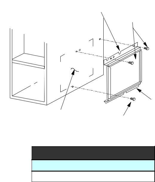
EXTERNAL FILTER RACK KIT
( EFR01 )
SLOTS IN FILTER
CLEAR SCREWS
ON UNIT
BLOWER DECK
SCREWS
UNIT SIDE
PANEL
FRONT |
|
|
|
OF UNIT |
|
|
|
|
|
FILTER RACK ASSEMBLY |
|
BASE |
|
(FACE FILTER OPENING |
|
|
TOWARDS FRONT |
||
OF UNIT |
|
||
RETURN AIR |
OF UNIT) |
||
|
|||
|
|
||
|
CUTOUT AREA |
LOWER EDGE |
|
|
|
||
|
|
SCREW |
EFR01 EXTERNAL FILTER RACK KIT
Used on Models
80% Upflow Model Furnaces
12

ACCESSORY WIRING DIAGRAMS
HIGH VOLTAGE!
DISCONNECT ALL POWER BEFORE SERVICING OR INSTALLING THIS
UNIT. MULTIPLE POWER SOURCES MAY BE PRESENT. FAILURE TO
DO SO MAY CAUSE PROPERTY DAMAGE, PERSONAL INJURY OR DEATH.
|
|
|
|
|
24VAC |
|
|
POWER SUPPLY |
|
|
P1-8 |
F1 |
3A |
+VDC |
|
|
R |
|
|
|
|||
INPUT |
|
|
|
POWER |
+5VDC |
|
|
FURNACE DEMAND |
|
|
P1-7 |
|
W1-FURN |
||
F |
W1 |
|
SUPPLY |
|
|||
|
|
|
|||||
OUTPUT |
|
|
|
|
W2-HP |
||
BLOWER FAN DEMAND |
U |
G |
P1-4 |
|
|
+VDC |
|
OUTPUT |
|
|
|
|
24VAC |
||
POWER SUPPLY INPUT |
R |
C |
P1-6 |
|
C |
|
G-STAT |
(COMMON) |
N |
|
|
|
K1 |
|
|
SECOND STAGE FURNACE |
W2 |
P1-5 |
|
|
|
|
|
DEMAND OUTPUT |
A |
|
|
|
|
G-FURN |
|
COMPRESSOR OUTPUT |
C |
Y |
P1-2 |
|
|
|
|
|
|
|
|
|
|
||
SECOND STAGE |
E |
Y2 |
P1-3 |
|
|
K2 |
Y2-HP |
COMPRESSOR OUTPUT |
|
|
|
|
|
||
REVERSING VALVE |
|
O |
P1-1 |
|
|
|
+VDC |
OUTPUT |
|
|
|
|
|
Y2-STAT |
|
|
|
|
24VAC |
|
|
||
|
|
|
|
|
Y2-FURN |
||
|
|
|
|
|
|
|
|
POWER SUPPLY OUT |
|
R |
P2-2 |
|
|
|
K4 |
TO THERMOSTAT |
T |
|
|
|
Q1 |
Y-STAT |
|
CALL FOR |
O |
P2-1 |
|
|
|
Y-FURN |
|
REVERSING VALVE |
H |
|
|
|
|
Y-HP |
|
CALL FOR |
E |
Y |
P2-7 |
|
|
|
|
COMPRESSOR |
|
|
|
|
|
||
CALL FOR |
R |
E |
P2-8 |
|
|
|
K3 |
EMERGENCY HEAT |
M |
|
|
|
|
|
|
CALL FOR |
|
P2-5 |
|
|
|
Q2 |
|
BLOWER FAN |
O |
G |
|
|
+5VDC |
|
|
|
|
|
|
||||
CALL FOR |
S |
W1 |
P2-9 |
|
|
|
|
FURNACE HEAT |
|
|
|
|
|
||
POWER SUPPLY COMMON |
T |
C |
P2-3 |
C |
E/W1 |
|
|
OUT TO THERMOSTAT |
A |
|
|
|
|
|
|
CALL FOR 2ND STAGE |
|
P2-4 |
|
1. 0K |
|
|
|
FURNACE HEAT |
T |
W2 |
|
|
|
|
|
|
|
|
|
|
|||
CALL FOR 2ND STAGE |
|
Y2 |
P2-6 |
|
|
|
|
COMPRESSOR |
|
|
|
|
MICROPROCESSOR |
|
|
|
|
|
24VAC |
O |
|
||
|
|
|
|
|
|||
POWER SUPPLY OUT |
|
R |
P3-9 |
|
|
|
|
TO HP CONTROL |
|
|
|
6. 8K |
|
|
|
HP CALL FOR FURNACE |
H |
W2 |
P3-8 |
|
|
|
|
(DURING DEFROST) |
|
|
|
|
|
||
REVERSING |
E |
O |
P3-7 |
|
Y |
|
|
VALVE OUTPUT |
|
|
|
|
|||
COMPRESSOR |
A |
Y |
P3-2 |
|
|
|
|
CONTACTOR OUTPUT |
T |
|
|
6. 8K |
|
|
|
POWER SUPPLY COMMON |
C |
P3-6 |
C |
|
|
|
|
OUT TO HP CONTROL |
P |
|
|
|
|
|
|
|
OT-NO |
P3-3 |
|
|
|
|
|
ODT (OUTDOOR |
|
|
|
|
|
||
U |
|
P3-1 |
|
|
|
|
|
THERMOSTAT) |
|
|
|
|
|
||
|
M OT-NC |
P3-4 |
|
|
|
|
|
2ND STAGE COMPRESSOR |
P |
OT-C |
P3-5 |
|
|
|
|
DEMAND OUTPUT |
|
Y2 |
|
|
|
|
|
|
|
|
|
|
|
||
|
|
|
|
|
|
|
|
|
2 |
|
|
|
|
|
|
|
BREAK FOR ODT |
|
|
|
|
|
|
|
1 |
|
|
|
|
|
|
ALL FUEL SYSTEM CONTROL BOARD - AFE18-60A
This wiring diagram is for reference only. Not all wiring is as shown above. Refer to the appropriate wiring diagram for the unit being serviced.
(For use with Heat Pumps in conjunction with 80% or 90% Single-Stage or Two-Stage Furnaces)
13
ACCESSORY WIRING DIAGRAMS
HIGH VOLTAGE!
DISCONNECT ALL POWER BEFORE SERVICING OR INSTALLING THIS
UNIT. MULTIPLE POWER SOURCES MAY BE PRESENT. FAILURE TO
DO SO MAY CAUSE PROPERTY DAMAGE, PERSONAL INJURY OR DEATH.
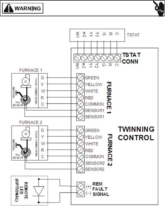
FURNACE TWINING KIT - FTK04 (UTEC Control Board)
This wiring diagram is for reference only. Not all wiring is as shown above. Refer to the appropriate wiring diagram for the unit being serviced.
(For use only with 80% or 90% Single-Stage Furnaces)
14

OPERATING INSTRUCTIONS
FOR YOUR SAFETY
READ BEFORE OPERATING
WARNING: If you do not follow these instructions explosion may result causing property damage, personal injury or loss of life.
A.This appliance does not have a pilot. It is equipped with an ignition device which automatically lights the burner. Do not try to light the burner by hand.
B. BEFORE OPERATING smell all around the appliance area for gas. Be sure to smell next to the floor because some gas is heavier than air and will settle on the floor.
WHAT TO DO IF YOU SMELL GAS  Do not try to light any appliance.
  Do not touch any electric switch; do not use any phone in your building.
  Immediately call your gas supplier from a neighbor's phone. Follow the gas supplier's instructions.
  If you cannot reach your gas supplier, call the fire department.
C.Use only your hand to push in or turn the gas control lever. Never use tools. If the lever will not push in or turn by hand, don't try to repair it, call a qualified service
technician. Force or attempted repair may result in a fire or explosion.
D.Do not use this appliance if any part has been underwater. Immediately call a qualified service technician to inspect the appliance and to replace any part of the control system and any gas control which has been underwater.
LIRE AVANT DE METTRE
EN MARCHELIRE
AVERTISSEMENT: Quiconque ne respecte pas á la lettre les instructions dans le présent manuel risque de déclecher un incendie ou une explosion entraînant des dammages matériels, des lésions corporelles ou la perte de vies humaines.
A. Cet appareil ne comporte pas de veilleuse. Il est muni d'un dispositif d'allumage qui allume automatiquement le brûleur. Ne pas tenter d'allumer le brûleur manuellement.
B. AVANT DE LE FAIRE FONCTIONNER, renifler tout autour de l'appariel pour déceler
une odeur de gaz. Renifler près du plancher, car certains gaz sont plus lourds que l'air et peuvent s'accumuler au niveau du so.l
QUE FAIRE S'IL Y A UNE ODEUR DE GAZ  Ne pas tenter d'allumer l'appariel
  Ne toucher aucun interrupteur électrique; n'utiliser aucun téléphone dans le bâtiment.
  Appeler immédiatement le fournisseur de gaz en employant le téléphone dún voisin. Respecter à la lettre les instructions du fournisseur de gaz.
  Si personne ne répond, appeler le service des incendies.
C. Ne pousser ou tourner le levier d'admission du gaz qu'à la main; ne jamais emploer d'outil à cet effet. Si la manette reste coincée, ne pas tenter de la réparer; appeler un technicien qualifié. Quiconque tente de forcer la manette ou de la reparer peut déclencher une explosion ou un incendie.
D. Ne pas se servir de cet appareil s'il a été plongé dans l'eau, complètement ou en partie. Appeler un technicien qualifié pour inspecter l'appareil et remplacer tout partie du système de contrôle et toute commande qui ont été plongés dans l'eau.
|
OPERATING INSTRUCTIONS |
|
MISE EN MARCHE |
|
1.STOP! Read the safety information above on this label.
2.Set the thermostat to lowest setting.
3.Turn off all power to the appliance.
4.This appliance is equipped with an ignition. device which automatically lights the burner. Do not try to light the burner by hand.
5. Push the gas control lever to "OFF" Position. |
|
|
|||||
Do not force. |
|
|
|
|
|
|
|
6. Wait five (5) minutes to clear out any gas. Then |
|
|
|||||
smell for gas, including near the floor. If you |
|
|
|||||
then smell gas, STOP! Follow |
"B" |
|
|
||||
in the safety. information above |
|
|
|||||
on this label if you don't smell |
|
|
|
|
|
|
|
gas, go to next step. |
GAS |
|
|
||||
7. Push gas control lever |
|
|
|||||
INLET |
|
|
|
||||
to "ON". |
|
|
|
||||
|
|
|
|
|
|
|
|
8. Replace access panel. |
|
|
|
|
|
|
|
|
|
|
|
|
|
|
|
9. Turn on all electric |
ARRIVEE |
|
|
||||
power to the appliance. |
DU GAZ |
|
|
||||
10.Set thermostat to desired setting. |
|
|
|||||
11.If the appliance will not operate, |
|
|
|||||
follow the instructions "To Turn |
|
|
|
|
|
|
|
Off Gas To Appliance" and call your |
|
|
|||||
service technician or gas company. |
|
|
|||||
|
1. |
|
. |
2. |
|
3. |
||
|
||
|
4. |
|
|
5. |
|
|
6. |
ROBINET A GAZ MANUEL, EN POS "ON/MARCHE"
7. |
8. |
9. |
10. |
11. |
MANUAL GAS
LEVER SHOWN
IN ON POSITION
ARRETÊR! Lisez les instructions de sécurité sur la portion supérieure de cette étiquette. Régler le thermostat à la température la plus basse Couper l'alimentation électrique de l'appareil. Cet appareil ménager étant doté d'un système d'allumage automatique, ne pas essayer à allumer le brûleur manuellement.
Pousse le levier du contrôle du gaz à "OFF/ ARRET" position.
Attendre cinq (5) minutes pour laisser echapper tout le gaz. Renifler tout autour de l'appareil, y compris près du plancher, pour déceler une odeur de gaz. Si c'est le cas, ARRETER! Passer à l'étape B des instructions de sécuritié sur la portion supérieure de cette étiquette. S'il n'y a pas d'odeur de gaz, passer à l'étape suivanté. Pousse le levier du contrôle du gaz à "ON/MARCHE" position. Remettre en place le panneau d'accés. Mettre l'appareil sous tension. Régler le thermostat à la température desirée. Si l'appareil ne se met pas en marche, suiyre les instructions intitulées. Comment coupler l'admission de gaz de l'appereil et appeler un technicien qualifié ou le fourrnisseur de gaz.
 TO TURN OFF GAS TO APPLIANCE
1.Set the thermostat to lowest setting.
2.Turn off all electric power to the appliance if service is to be performed.
3. Push the gas control lever to "OFF" Position. Do not force. 4. Replace control access panel.
POUR COUPER L'ADMISSION
DE GAZ DE L'APPAREIL
1.Régler le thermostat à la température la plus basse.
2.Couper l'alimentation électrique de l'appareil s'il faut procéder à des opérations d'entretien.
3.Pousse le levier du contrôle du gaz à "OFF / ARRET" position.
Ne pas forcer.
4.Remettre en place le panneau d'accès.
11072712
15
OPERATING INSTRUCTIONS
FOR YOUR SAFETY
READ BEFORE OPERATING
WARNING: If you do not follow these instructions exactly,a fire or explosion may result causing property damage,personal injury or loss of life.
A.This appliance does not have a pilot. It is equipped with an ignition device which automatically lights the burner. Do not tryto light the burner by hand.
B.BEFOREOPERATING smell all around the appliance area for gas. Be sure to smell next to the floor
because some gas is heavier than air and will settle on the floor.
WHAT TO DO IF YOU SMELL GAS
Do not try to light any appliance.
Do not touch any electric switch;
do not use any phone in your building.
Immediately call your gas supplier from a neighbor's phone. Follow the gas supplier's instructions.
If you cannot reach your gas supplier, call the fire department.
C.Use only your hand to push in or turn the gas control lever. Never use tools. If the lever will not push in or turn by hand, don't try to repair it,call a qualified service
technician. Force or attempted repair may result in a fire or explosion.
D.Do not use this appliance if any part has been underwater. Immediately call a qualified service technician to inspect the appliance and to replace any part of the control
system and any gas control which has been underwater.
LIRE AVANT DE METTRE
EN MARCHELIRE
AVERTISSEMENT: Quiconque ne respecte pas à
la lettre les instructions dans le presént manuel risque de déclencher un incendie ou une explosion entraînant des dommages matériels, des lesions
corporelles ou la perte de vies humaines.
A.Cet appareil ne comporte pas de veilleuse. Ilest muni d'undispositif d'allumage qui allume
automatiquement le brûleur. Ne pas tenter d'allumer le brûleur manuellement.
B.AVANT DE LE FAIRE FONCTIONNER,
renifler tout autour del'appariel pour decéler une odeur de gaz. Renifler prés du plancher, car certains gaz sont plus lourds que l'airet
peuvent s'accumuler au niveau du sol.
QUEFAIRE S'IL Y A UNE ODEUR DE GAZ
 Ne pas tenter d'allumer d'appareils.
Ne toucher à aucun interrupteur; ne pas vous servir des téléphones dans le bâtiment.
Appelez immédiatement votre fournisseur de gaz depuis un voisin. Suivez les instructions du fournisseur de gaz
Sivous ne pouvez rejoindre le fournisseur de gaz, appelez le service des incendies.»
C.Ne pousser ou tourner la manette d'admission du gaz
qu'à la main. Ne jamais emploer d'outil à cette fin. Si la manette reste coincée, ne tenter pas de la
réparer; appelez un technicien qualifié. Quiconque tente de forcer la manette ou de la réparer peut
provoquer uneexplosion ou un incendie.»
D.Ne pas se servir de cet appareil s'il a été plongé dans l'eau, même partiellement. Faire inspecter l'appareil
par un technicien qualifié et remplacer toutr partie du systéme de contrôle et toute commande qui ont été
plongées dans l'eau.»
OPERATING INSTRUCTIONS 
 MISEEN MARCHE
1. STOP. Read the safety information above on this label.
2.Set the thermostat to lowest setting. 3.Turn off all electric power to the appliance.
4.This appliance is equipped with an ignition device which automatically lights the burner. Do not try to light the burner by hand.
5. Push the gas control lever to "OFF” Position.
Do not force. |
|
|
|
6.Wait five (5) minutes to clear out any gas.Then |
ROBINETAGAZ |
||
smell for gas, including near the floor. If you |
|||
then smell gas, STOP. Follow "B" |
MANUEL,ENPOS |
||
in the safety information above |
|
"ON/MARCHE" |
|
on this label if you don't smell |
GAS |
|
|
gas,go to next step. |
|
||
INLET |
|
||
7.Push gas control lever |
|
||
|
|
||
to "ON". |
|
|
|
8.Replace access panel. |
ARRIVEE |
|
|
9. Turn on all electric |
DUGAZ |
|
|
power to the appliance. |
|
|
|
10.Setthermostattodesiredsetting. |
MANUAL GAS |
||
11.If the appliance will not operate, |
|||
follow the instructions “ToTurn |
|
LEVER SHOWN |
|
|
IN "ON" POS |
||
Off Gas ToAppliance" and call your |
|||
|
|||
service technician or gas company.
1. ARRÊTEZ Lisez les instructions de sécurité dans la
. section supérieure de cette étiquette.
2.Régler le thermostat à la température la plus basse. 3.Couper l'alimentation électrique de l'appareil.
4.Cet appareil menager etant dote d'un systeme d'allumage automatique, ne pas essayer à allumer le brûleur manuellement.
5.Pousse le levier du contrÔle du gaz a "OFF/ARRET” position.
6.Attendre cinq (5) minutes pour laisser echapper tout le
gaz. Renifler tout autour de l'appareil, y comprisprés du plancher, pour déceler une odeur de gaz. Si c'est le cas,
ARRÊTEZ. Passer à l'etape B des instructions de securite sur la portion superieure de cette etiquette.
S'il n'y a pas d'odeur de gaz, passer à l'etàpe suivante.
7.Pousse le levier du contrôle du gaz à "ON/MARCHE” position.
8.Remettre en place le panneau d'accés. 9.Mettre l'appareil sous tension.
10.Régler le thermostat à la température désirée. 11.Si l'appareil ne se met pas en marche,suivre les
instructions intitulées Comment couper l'admission de gaz de l'appareil et appeler un technicien qualifié ou le fournisseur de gaz.
 TOTURNOFFGASTOAPPLIANCE
1.Set the thermostat to lowest setting.
2. Turn off all electric power to the appliance
if service is to be performed.
3.Push the gas control lever to "OFF” Position. Do not force.
4.Replace control access panel.
POUR COUPER L'ADMISSION DE GAZ DE L'APPAREIL
1.Régler le thermostat à la température la plus bassé. 2.Couper l'alimentation électrique de l'appareil s'il
faut procéder à des operations d'entretien.
3.Pousse le levier du contrôle du gaz à "OFF/ARRET" position.
Ne pas forcer.
4.Remettre en place le panneau d'accés.
0140F00681 REV A
16

OPERATING INSTRUCTIONS
 FOR YOUR SAFETY READ BEFORE OPERATING
If you do not follow these instructions exactly, a fire or explosion may result causing property damage, personal injury or loss of life.
A.This appliance does not have a pilot. It is equipped with an ignition device which
automatically lights the burners. Do not try to light the burners by hand.
B.BEFORE OPERATING smell around the appliance area for gas. Be sure to
smell next to the floor because some gas is heavier than air and will settle on the floor.
WHAT TO DO IF YOU SMELL GAS  Do not try to light any appliance.
 Do not touch any electric switch;
do not use any telephone in your building.
 Immediately call your supplier
from a neighbor's phone. Follow the gas suppliers instructions.
 If you cannot reach your gas supplier, call the fire department.
C. Use only your hand to move the gas
control switch or knob. Never use tools. If the gas control switch or knob
will not operate, don't try to repair it, call a qualified service technician. Force or attempted repair may result in
a fire or explosion.
D. Do not use this appliance if any part has been under water. Immediately call
a qualified service technician to inspect
the appliance and to replace any part of the control system and any gas control which has been under water.
 OPERATING INSTRUCTIONS
1.STOP! Read the safety information above on this label.
2.Set the thermostat to lowest setting.
3.Turn off all electric power to the appliance.
4.This appliance is equipped with an
automatic ignition system which automatically lights the burners. Do not
try to light the burners by hand.
5.Remove control access panel.
6.Move the gas control switch or knob to "OFF".
GAS CONTROL |
SWITCH SHOWN |
IN "ON" POSITION |
7. Wait five (5) minutes to clear out any gas. If you then smell gas, STOP!
Follow "B" in the safety information
above on this label. If you don't smell gas, go to the next step.
8.Move the gas control switch or knob to "ON".
9.Replace control access panel.
10.Turn on all electric power to the appliance.
11.Set the thermostat to the desired setting.
12.If the appliance will not operate,
follow the instructions "To Turn Off Gas To Appliance" and call your service technician or gas supplier.
 TO TURN OFF GAS TO APPLIANCE
1. |
Set the thermostat to its lowest setting. |
4. |
Move the gas control switch or knob |
2. |
Turn off all electric power to the |
to "OFF". Do not force. |
|
appliance if service is to be performed. |
5. |
Replace control access panel. |
|
3. |
Remove control access panel. |
|
|
WARNING: Improper
installation, adjustment, alteration, service or
maintenance can
cause injury or property damage.
Refer to the user's
information manual provided with this furnace. For assistance
or additional information consult a qualified
installer, service agency or the gas supplier.
This furnace must be installed in accordance
with the manufacturers instructions and local
codes. In the absence of local codes, follow
the National Fuel Gas Code, ANSI Z223.1.
WARNING: If not installed, operated and maintained in
accordance with the
manufacturer's instructions, this
product could expose
you to substances in fuel combustion
which can cause death or serious
illness and which are known to the
State of California to cause cancer, birth
defects or other reproductive harm.
This product contains fiberglass insulation. Fiberglass insulation
contains a chemical known by the State of
California to cause cancer.
FOR YOUR SAFETY Do not store or use gasoline or other flammable vapors and liquids in the vicinity of this or any other appliance.
17

PRODUCT DESIGN
Safety
Please adhere to the following warnings and cautions when installing, adjusting, altering, servicing, or operating the furnace.
 WARNING
TO PREVENT PERSONAL INJURY OR DEATH DUE TO IMPROPER INSTALLATION, ADJUSTMENT, ALTERATION, SERVICE OR MAINTENANCE, REFER TO THIS MANUAL. FOR ADDITIONAL ASSISTANCE OR INFORMATION, CONSULT A QUALIFIED INSTALLER, SERVICE AGENCY OR THE GAS SUPPLIER.
 WARNING
THIS PRODUCT CONTAINS OR PRODUCES A CHEMICAL OR CHEMICALS WHICH MAY CAUSE SERIOUS ILLNESS OR DEATH AND WHICH ARE KNOWN TO THE STATE OF CALIFORNIA TO CAUSE CANCER, BIRTH DEFECTS OR OTHER REPRODUCTIVE HARM.
 WARNING
TO PREVENT POSSIBLE PROPERTY DAMAGE, PERSONAL INJURY OR DEATH DUE TO ELECTRICAL SHOCK, THE FURNACE MUST BE LOCATED TO PROTECT THE ELECTRICAL COMPONENTS FROM WATER.
Charge (ESD) Precautions
NOTE: Discharge body’s static electricity before touching unit. An electrostatic discharge can adversely affect electrical components.
Use the following precautions during furnace installation and servicing to protect the integrated control module from damage. By putting the furnace, the control, and the person at the same electrostatic potential, these steps will help avoid exposing the integrated control module to electrostatic discharge. This procedure is applicable to both installed and uninstalled (ungrounded) furnaces.
1.Disconnect all power to the furnace. Do not touch the integrated control module or any wire connected to the control prior to discharging your body’s electrostatic charge to ground.
2.Firmly touch a clean, unpainted, metal surface of the furnace near the control. Any tools held in a person’s hand during grounding will be discharged.
3.Service integrated control module or connecting wiring following the discharge process in Step 2. Use caution not to recharge your body with static electricity; (i.e., do not move or shuffle your feet, do not touch ungrounded objects, etc.). If you come in contact with an ungrounded object, repeat Step 2 before touching control or wires.
4.Discharge any static electricity from your body to ground before removing a new control from its container. Follow Steps 1 through 3 if installing the control on a furnace. Return any old or new controls to their containers before touching any ungrounded object.
Product Application
This product is designed for use as a residential home gas furnace. It is not designed or certified for use in mobile home, trailer, or recreational vehicle applications.
This furnace can be used in the following non-industrial commercial applications: Schools, Office buildings, Churches,
Retail stores, Nursing homes, Hotels/motels, Common or office areas. In such applications, the furnace must be installed with the installation instructions.
Goodman & Amana® 80% furnaces are ETL certified appliances and are appropriate for use with natural or propane gas. (NOTE: If using propane gas, a propane conversion kit is required).
IMPORTANT NOTE: The 80% furnace cannot be installed as a direct vent (i.e.., sealed combustion) furnace. The burner box is present only to help reduce sound transmission from the burners to the occupied space.
To ensure proper installation, operation and servicing, thoroughly read the installation and service manuals for specifics pertaining to the installation, servicing and application of this product.
 WARNING
POSSIBLE PROPERTY DAMAGE, PERSONAL INJURY OR DEATH DUE TO FIRE, EXPLOSION, SMOKE, SOOT, CONDENSTAION, ELECTRICAL SHOCK OR CARBON MONOXIDE MAY RESULT FROM IMPROPER INSTALLATION, REPAIR, OPERATION, OR MAINTENANCE OF THIS PRODUCT.
 WARNING
TO PREVENT PROPERTY DAMAGE, PERSONAL INJURY OR DEATH DUE TO FIRE, DO NOT INSTALL THIS FURNACE IN A MOBILE HOME, TRAILER, OR RECREATIONAL VEHICLE.
To ensure proper furnace operation, install, operate, maintain and service the furnace in accordance with the installation, operation and service instructions, all local building codes and ordinances. In their absence, follow the latest edition of the National Fuel Gas Code (NFPA 54/ANSI Z223.1), and/or CAN/CGA B149 Installation Codes, local plumbing or waste water codes, and other applicable codes.
A copy of the National Fuel Gas Code (NFPA 54/ANSI Z223.1) can be obtained from any of the following:
American National Standards Institute 1430 Broadway
New York, NY 10018
National Fire Protection Association
1 Batterymarch Park
Quincy, MA 02269
18
 Loading...