


CAUF
5151 San Felipe, Suite 500, Houston, TX 77056
© 2005-2006, 2012-2013, 2015-2018 Goodman Manufacturing Company , L.P .
1. Important Safety Instructions
The following symbols and labels are used throughout this
manual to indicate immediate or potential safety hazards. It is
the owner’s and installer’s responsibility to read and comply with
all safety information and instructions accompanying these sym-
bols. Failure to heed safety information increases the risk of
personal injury, property damage, and/or product damage.
HIGH VOLTAGE!
D
ISCONNECT
ALL
POWER
BEFORE
SERVICING
OR
INSTALLING
THIS
UNIT
. M
ULTIPLE
POWER
SOURCES
MAY
BE
PRESENT
. F
AILURE
TO
DO
SO
MAY
CAUSE
PROPERTY
DAMAGE
,
PERSONAL
INJURY
OR
DEATH
.
O
NLY
PERSONNEL
THAT
HAVE
BEEN
TRAINED
TO
INSTALL
,
ADJUST
,
SERVICE
OR
REPAIR
(
HEREINAFTER
, “
SERVICE
”)
THE
EQUIPMENT
SPECIFIED
IN
THIS
MANUAL
SHOULD
SERVICE
THE
EQUIPMENT
. T
HE
MANUFACTURER
WILL
NOT
BE
RESPONSIBLE
FOR
ANY
INJURY
OR
PROPERTY
DAMAGE
ARISING
FROM
IMPROPER
SERVICE
OR
SERVICE
PROCEDURES
. I
F
YOU
SERVICE
THIS
UNIT
,
YOU
ASSUME
RESPONSIBILITY
FOR
ANY
INJURY
OR
PROPERTY
DAMAGE
WHICH
MAY
RESULT
. I
N
ADDITION
,
IN
JURISDICTIONS
THAT
REQUIRE
ONE
OR
MORE
LICENSES
TO
SERVICE
THE
EQUIPMENT
SPECIFIED
IN
THIS
MANUAL
,
ONLY
LICENSED
PERSONNEL
SHOULD
SERVICE
THE
EQUIPMENT
. I
MPROPER
INSTALLATION
,
ADJUSTMENT
,
SERVICING
OR
REPAIR
OF
THE
EQUIPMENT
SPECIFIED
IN
THIS
MANUAL
,
OR
ATTEMPTING
TO
INSTALL
,
ADJUST
,
SERVICE
OR
REPAIR
THE
EQUIPMENT
SPECIFIED
IN
THIS
MANUAL
WITHOUT
PROPER
TRAINING
MAY
RESULT
IN
PRODUCT
DAMAGE
,
PROPERTY
DAMAGE
,
PERSONAL
INJURY
OR
DEATH
.
2. Shipping Inspection
Upon receiving the product, inspect it for damage from shipment.
Shipping damage, and subsequent investigation is the responsi-
bility of the carrier. Verify the model number, specifications,
and accessories are correct prior to installation. The distributor
or manufacturer will not accept claims from dealers for trans-
portation damage or installation of incorrectly shipped units.
2. 1 Handling
Use caution when transporting / carrying unit.. Do not carry
unit with hooks or sharp object. The preferred method of
carrying the unit after arrival at the job site is to carry by two-
wheel hand truck from the back or sides or by hand by carry-
ing at the cabinet corners.
3. Codes & Regulations
This product is designed and manufactured to comply with na-
tional codes. Installation in accordance with such codes and/or
prevailing local codes/regulations is the responsibility of the in-
staller. The manufacturer assumes no responsibility for equip-
ment installed in violation of any codes or regulations.
UPFLOW/DOWNFLOW COILS
INSTALLATION INSTRUCTIONS
The United States Environmental Protection Agency (EPA) has
issued various regulations regarding the introduction and dis-
posal of refrigerants. Failure to follow these regulations may
harm the environment and can lead to the imposition of sub-
stantial fines. Should you have any questions please contact the
local office of the EPA.
4. Replacement Parts
Inspect the unit to verify all required components are present
and intact. Report any missing components immediately to the
manufacturer or to the distributor. Make sure to include the full
product model number and serial number when reporting and/
or obtaining service parts. Replacement parts for this product
are available through your contractor or local distributor. For
the location of your nearest distributor consult the white busi-
ness pages, the yellow page section of the local telephone book
or contact:
HOMEOWNER SUPPORT
GOODMAN MANUFACTURING COMPANY, L.P.
19001 KERMIER ROAD
WALLER, TEXAS 77484
877– 254 – 4729
5. Pre-Installation Instructions
5.1 Preparation
Keep this document with the unit. Carefully read all instruc-
tions for the installation prior to installing product. Make sure
each step or procedure is understood and any special consid-
erations are taken into account before starting installation.
Assemble all tools, hardware and supplies needed to com-
plete the installation. Some items may need to be purchased
locally. Make sure everything needed to install the product is
on hand before starting.
5.2 Clearances
Refrigerant lines must be routed depending on configuration
of unit to maintain the required 24” minimum clearance for
service. Consult all appropriate regulatory codes prior to de-
termining final clearances. In installations that may lead to
physical damage (i.e. a garage) it is advised to install a protec-
tive barrier to prevent such damage. Always install units such
that a positive slope in condensate line (1/4" per foot) is al-
lowed.
6. Application Information
Coils are designed for indoor installation only and must be in-
stalled downstream (discharge air) of the furnace. The CAPF/CAPT
product line may be installed in upflow or downflow orienta-
tions.
is a registered trademark of Maytag Corporation or its related companies and is used under license. All rights reserved.
IO-284H
02/2018
2
7. Condensate Drain Piping
In all cooling applications where condensate overflow may cause
damage, a secondary drain pan must be provided by the installer
and placed under the entire unit with a separate drain line prop-
erly sloped and terminated in an area visible to the owner. This
secondary drain pan can provide extra protection to the area
under the unit should the primary drain plug up and overflow. As
expressed in our product warranty, we will not be liable for any
damages, structural or otherwise due to the failure to follow this
installation requirement.
Condensate drain connections are located in the drain pan at the
bottom of the coil/enclosure assembly. Use the female (3/4” FPT)
threaded fitting that protrudes outside of the enclosure for exter-
nal connections. The connectors required are 3/4" NPT male, ei-
ther PVC or metal pipe, and must be hand tightened to a torque of
no more than 37 in-lbs. to prevent damage to the drain pan con-
nection. An insertion depth between .36 to .49 inches (3-5 turns)
should be expected at this torque.
1. Ensure drain pan hole is NOT obstructed.
2. To prevent potential sweating and dripping on finished space,
it may be necessary to insulate the condensate drain line
located inside the building. Use Armaflex
®
or similar mate-
rial.
A Secondary Condensate Drain Connection, now called for by many
building codes, has been provided. Pitch the drain line 1/4" per
foot to provide free drainage. Provide required support to drain
line to prevent bowing. Install a condensate trap in the primary
drain line to ensure proper drainage. If the secondary drain line
is required, run the line separately from the primary drain and
end it where condensate discharge can be easily seen.
CAUTION
I
F
SECONDARY
DRAIN
IS
NOT
INSTALLED
,
THE
SECONDARY
ACCESS
MUST
BE
PLUGGED
.
8. Refrigerant Lines
CAUTION
T
HE
COIL
IS
SHIPPED
UNDER
PRESSURE
WITH
AN
R-410A
GAS
MIXTURE
. U
SE
APPROPRIATE
SERVICE
TOOLS
AND
FOLLOW
THESE
INSTRUCTIONS
TO
PREVENT
INJURY
.
A
QUENCHING
CLOTH
IS
STRONGLY
RECOMMENDED
TO
PREVENT
SCORCHING
OR
MARRING
OF
THE
EQUIPMENT
FINISH
WHEN
BRAZING
CLOSE
TO
THE
PAINTED
SURFACES
. U
SE
BRAZING
ALLOY
OF
5%
MINIMUM
SILVER
CONTENT
.
NOTE: Refrigerant tubing must be routed to allow adequate ac-
cess for servicing and maintenance of the unit.
Do not handle coil assembly with manifold or flowrator tubes.
Doing so may result in damage to the tubing joints. Always use
clean gloves for handling coil assemblies.
8. 1 Tubing Size/Length
For the correct tubing size, follow the specification for the
condenser/heat pump. Give special consideration to minimiz-
ing the length of refrigerant tubing when installing coils. Refer
to Remote Cooling/Heat Pump Technical Publication TP-107*
Long Line Set Application R-410A for guidelines for line lengths
over 80’. Leave a minimum 3" straight in line set from braze
joints before any bends.
8.2Tubing Preparation
All cut ends are to be round, burr free, and cleaned. Any other
condition increases the chance of a refrigerant leak. Use a
pipe cutter to remove the closed end of the spun closed suction
line.
8.3Brazing
Braze joints should be made only with the connections pro-
vided external to the cabinet. Do not alter the cabinet nor
braze inside the cabinet. To avoid overheating after brazing,
quench all brazed joints with water or a wet rag.
A
PPLYING
TOO
MUCH
HEAT
TO
ANY
TUBE
CAN
MELT
THE
TUBE
. T
ORCH
HEAT
REQUIRED
TO
BRAZE
TUBES
OF
VARIOUS
SIZES
MUST
BE
PROPORTIONAL
TO
THE
SIZE
OF
THE
TUBE
.
S
ERVICE
PERSONNEL
MUST
USE
THE
APPROPRIATE
HEAT
LEVEL
FOR
THE
SIZE
OF
THE
TUBE
BEING
BRAZED
.
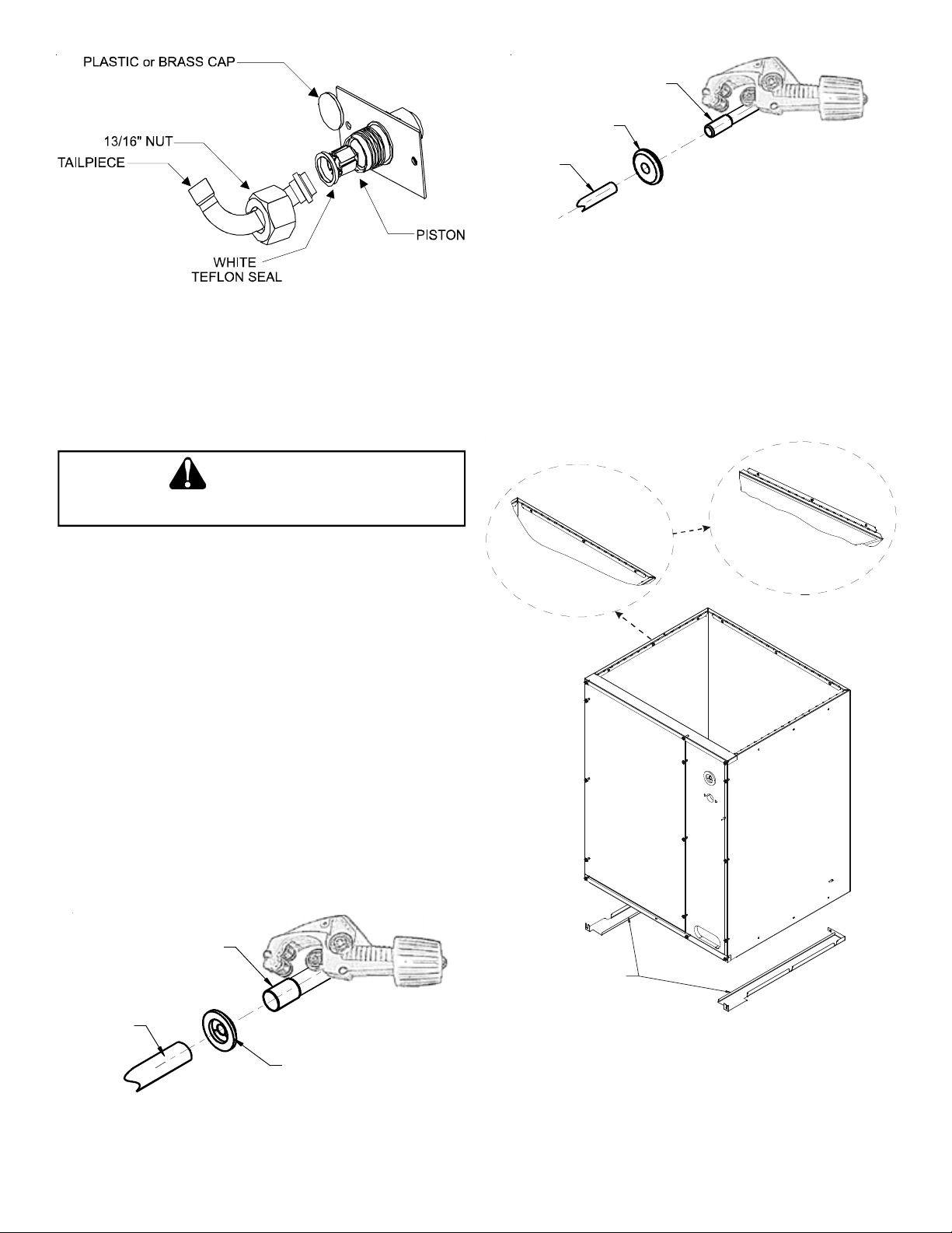
8.4Special Instructions for Flowrator (Piston) Version
Coils in flowrator version are equipped with a check style
flowrator for refrigerant management. For most installations
with matching applications, no change to the flowrator piston
is required. However, in mix-matched applications, a piston
change may be required. See the piston kit chart or consult
your local distributor for details regarding mix-matched pis-
ton sizing. If the mix-matched application requires a different
piston size, change the piston in the distributor on the indoor
coil before installing the coil and follow the procedure shown
below.
8.5Tubing Connections for Flowrator Model
1. Loosen the 13/16 nut 1 TURN ONLY to allow high pressure
tracer gas to escape. No gas indicates a possible leak.
2. After the gas has escaped, remove the nut and discard the
plastic or brass cap.
3. Remove the check piston to verify it is correct and then re-
place the piston. See piston kit chart in instructions.
4. Use a tube cutter to remove the spin closure on the suc-
tion line. DO NOT USE A CUTTING METHOD THAT WOULD
RESULT IN THE GENERATION OF COPPER SHAVINGS OR
COPPER DUST.
5. Slide the 13/16 nut into place on the tailpiece supplied in
the literature bag or with the unit.
6. Insert liquid line into the supplied tailpiece.
3
Figure 1
7. Insert the suction line into the connection, slide the insula-
tion and the rubber grommet at least 18" away from the
braze joint. Braze both liquid and suction line joints.
8. AFTER THE TAILPIECE HAS COOLED, confirm position of the
white Teflon
®
seal and hand tighten the 13/16 nut.
E
XCESSIVE
TORQUE
CAN
CAUSE
ORIFICES
TO
STICK
. U
SE
THE
PROPER
TORQUE
SETTINGS
WHEN
TIGHTENING
ORIFICES
.
CAUTION
9. Torque the 13/16” nut to 10-20 ft-lbs. or 1/6 turn past hand
tight.
10. Replace suction line grommet and insulation.
8. 6 Tubing Connections for TXV Version
TXV models come with factory installed non-adjustable TXV
with the bulb permanently located on the suction tube.
1. Remove coil access panel.
2. Remove access valve fitting cap and depress the valve stem
in access fitting to release pressure. No pressure indicates
possible leak.
3. Replace the refrigerant tubing panel.
4. Remove the spin closure on both the liquid and suction
tubes using a tubing cutter. DO NOT USE A CUTTING
METHOD THAT WOULD RESULT IN THE GENERATION OF
COPPER SHAVINGS OR COPPER DUST.
SUCTION
LINE SET
SUCTION
TUBE
RUBBER
GROMMET
Figure 2.1
LIQUID
LINE SET
LIQUID
LINE
RUBBER
GROMMET
Figure 2.2
5. Insert liquid line set into liquid tube expansion and slide
grommet about 18" away from braze joint.
6. Insert suction line set into suction tube expansion and slide
insulation and grommet about 18" away from braze joint.
7. Braze suction and liquid line joints.
9. Top flange s can be bent f or e ase in inst allation t o the
duct flanges.
Unfolded View
Top Flange D etail V iew
FILLER
PLATE
Figure 3
10.Filler Plates
Filler plates are supplied on all 17.5, 21, & 24.5 inch chassis to be
used for adapting the unit to a furnace one size smaller. If the
plenum and furnace openings are the same size, the filler plates
must be removed. See Figure 3.
 Loading...