


Service Instructions
GME8 & AMEH8
Modified Two Stage Furnace
with EEM Motor
This manual is to be used by qualified, professionally trained HVAC technicians only. Goodman does not assume any responsibility for property damage or personal injury due to improper service procedures or services performed by an unqualified person.
Copyright © 2006-2013 Goodman Manufacturing Company, L.P.


 ® is a trademark of Maytag Corporation and is used under license. All rights reserved.
RS6621001
July 2013
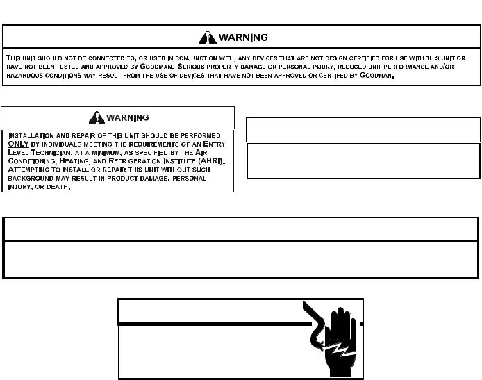
TABLE OF CONTENTS
IMPORTANT INFORMATION ........................... |
2-3 |
PRODUCT IDENTIFICATION .......................... |
4-6 |
ACCESSORIES ............................................... |
7-8 |
OPERATING INSTRUCTIONS ............................ |
9 |
PRODUCT DESIGN .................................... |
10-30 |
SYSTEM OPERATION ................................ |
31-33 |
TROUBLESHOOTING ................................. |
34-35 |
POLARIZATION & PHASING ............................. |
36 |
MAINTENANCE ............................................ |
37-38 |
SERVICING .................................................. |
39-53 |
SERVICING TABLE OF CONTENTS ................ |
41 |
ACCESSORY WIRING DIAGRAM ..................... |
54 |
IMPORTANTINFORMATION
Pride and workmanship go into every product to provide our customers with quality products. It is possible, however, that during its lifetime a product may require service. Products should be serviced only by a qualified service technician who is familiar with the safety procedures required in the repair and who is equipped with the proper tools, parts, testing instruments and the appropriate service manual. REVIEW ALL SERVICE INFORMATION IN THE APPROPRIATE
SERVICE MANUAL BEFORE BEGINNING REPAIRS.
IMPORTANT NOTICES FOR CONSUMERS AND SERVICERS
 RECOGNIZE SAFETY SYMBOLS, WORDS AND LABELS
 WARNING
TO PREVENT THE RISK OF PROPERTY DAMAGE, PERSONAL INJURY, OR DEATH,
DO NOT STORE COMBUSTIBLE MATERIALS OR USE GASOLINE OR OTHER
FLAMMABLE LIQUIDS OR VAPORS IN THE VICINITY OF THIS APPLIANCE.
 WARNING
GOODMAN WILL NOT BE RESPONSIBLE FOR ANY INJURY OR PROPERTY DAMAGE ARISING FROM IMPROPER SERVICE OR SERVICE PROCEDURES. IF YOU INSTALL OR PERFORM SERVICE ON THIS UNIT, YOU ASSUME RESPONSIBILITY FOR ANY PERSONAL INJURY OR PROPERTY DAMAGE WHICH MAY RESULT. MANY JURISDICTIONS REQUIRE A LICENSE TO INSTALL OR SERVICE HEATING AND AIR CONDITIONING EQUIPMENT.
 WARNING
HIGH VOLTAGE
DISCONNECT ALL POWER BEFORE SERVICING OR
INSTALLING THIS UNIT. MULTIPLE POWER SOURCES MAY
BE PRESENT. FAILURE TO DO SO MAY CAUSE PROPERTY
DAMAGE, PERSONAL INJURY OR DEATH.
2

IMPORTANTINFORMATION
Special Warning for Installation of Furnace or Air Handling Units in
Enclosed Areas such as Garages, Utility Rooms or Parking Areas
Carbon monoxide producing devices (such as an automobile, space heater, gas water heater, etc.) should not be operated in enclosed areas such as unventilated garages, utility rooms or parking areas because of the danger of carbon monoxide (CO) poisoning resulting from the exhaust emissions. If a furnace or air handler is installed in an enclosed area such as a garage, utility room or parking area and a carbon monoxide producing device is operated therein, there must be adequate, direct outside ventilation.
This ventilation is necessary to avoid the danger of CO poisoning which can occur if a carbon monoxide producing device continues to operate in the enclosed area. Carbon monoxide emissions can be (re)circulated throughout the structure if the furnace or air handler is operating in any mode.
CO can cause serious illness including permanent brain damage or death.
To locate an authorized servicer, please consult your telephone book or the dealer from whom you purchased this product. For further assistance, please contact:
CONSUMERINFORMATIONLINE |
CONSUMERINFORMATIONLINE |
GOODMAN® BRAND PRODUCTS |
AMANA® BRAND PRODUCTS |
TOLL FREE |
TOLL FREE |
1-877-254-4729 (U.S. only) |
1-877-254-4729 (U.S. only) |
email us at: |
email us at: |
customerservice@goodmanmfg.com |
hac.consumer.affairs@amanahvac.com |
fax us at: (731) 856-1821 |
fax us at: (731) 856-1821 |
(Not a technical assistance line for dealers.) |
(Not a technical assistance line for dealers.) |
Outside the U.S., call 1-713-861-2500.
(Not a technical assistance line for dealers.) Your telephone company will bill you for the call.
3

PRODUCT IDENTIFICATION
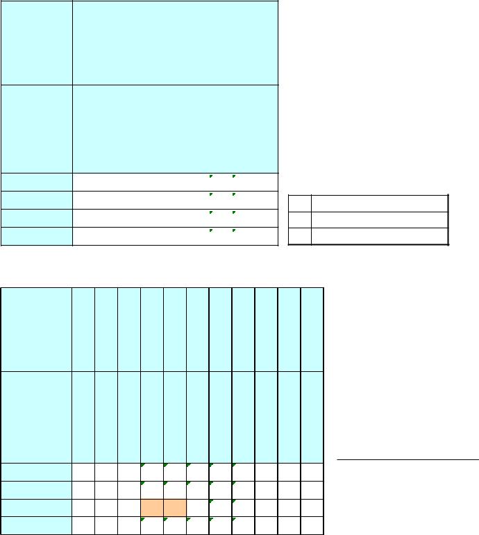
The model and manufacturing number are used for positive identification of component parts used in manufacturing. Please use these numbers when requesting service or parts information.
A |
M |
E |
H |
9 |
6 |
0 |
6 |
0 |
3 |
B |
N |
A |
A |
1 |
2 |
3 |
4 |
5 |
6 |
7 |
8 |
9 |
10 |
11 |
12 |
13 |
14 |
Brand |
|
|
|
|
|
|
|
|
|
|
|
|
Minor Revision |
A- Amana |
|
|
|
|
|
|
|
|
|
|
|
|
A - Initial Release |
G- Goodman |
|
|
|
|
|
|
|
|
|
|
|
|
B - 1st Revision |
Configuration |
|
|
|
|
|
|
|
|
|
|
|
|
Major Revision |
M - Upflow/Horizontal |
|
|
|
|
|
|
|
|
|
|
|
|
A - Initial Release |
C - Downflow/Horizontal |
|
|
|
|
|
|
|
|
|
|
|
|
B - 1st Revision |
K - Dedicated Upflow |
|
|
|
|
|
|
|
|
|
|
|
|
|
D - Dedicated Downflow |
|
|
|
|
|
|
|
|
|
|
|
|
Nox |
|
|
|
|
|
|
|
|
|
|
|
|
|
N - Natural Gas |
Motor |
|
|
|
|
|
|
|
|
|
|
|
|
X - Low NOx |
V - Variable Speed/ComfortNet |
|
|
|
|
|
|
|
|
|
|
|
|
|
E - High Efficiency |
|
|
|
|
|
|
|
|
|
|
|
|
Cabinet Width |
S - Single Speed |
|
|
|
|
|
|
|
|
|
|
|
|
A - 14" |
|
|
|
|
|
|
|
|
|
|
|
|
|
B - 17.5" |
Gas Valve |
|
|
|
|
|
|
|
|
|
|
|
|
C - 21" |
M - Modulating |
|
|
|
|
|
|
|
|
|
|
|
|
D - 24.5" |
C - 2 Stage |
|
|
|
|
|
|
|
|
|
|
|
|
|
H - Convertible 2 Stage |
|
|
|
|
|
|
|
|
|
|
|
|
Maximum CFM |
S - Single Stage |
|
|
|
|
|
|
|
|
|
|
|
|
3 - 1200 CFM |
|
|
|
|
|
|
|
|
|
|
|
|
|
4 - 1600 CFM |
AFUE |
|
|
|
|
|
|
|
|
|
|
|
|
5 - 2000 CFM |
97 - 97% AFUE |
|
|
|
|
|
|
|
|
|
|
|
|
|
80 - 80% AFUE |
|
|
|
|
|
|
|
|
|
|
|
|
|
MBTU/h
40 - 40,000
60 - 60,000
80 - 80,000
100 - 100,000
120 - 120,000
4

PRODUCT IDENTIFICATION
MODEL # |
MFG. # |
80% GAS FURNACES |
|
|
AMEH800603B* |
Amana® Brand 80%Gas Furnace, 33 3/8" tall, Upflow/Horizontal Left or Right of left |
|
|
installation positions. Induced draft, two tone cabinet and panels. EcoTech EEM motor, |
||
AMEH8 |
AMEH800805C* |
two stage gas valve with timed second stage operation, can accommodate two stage |
|
AMEH800805D* |
condensing unit operation. 120 volt silicon nitride hot surface ignition with integrated |
||
|
|||
|
AMEH801005C |
circuit board. Left or right side gas entry. Stainless steel tubular heat exchanger. |
|
|
|
Chassis widths 17.5", 21", 24.5". Meets <2% cabinet low leak. |
|
|
|
Goodman® Brand 80% Gas Furnace, 39" tall, Upflow/Horizontal Left or Right, Induced |
|
|
GME8*****AA |
Draft, new grey painted cabinet and front panels, X-13 motor, standardized blower decks |
|
|
and a 120V silicon nitride igniter. Left or right gas pipe entry. The furnaces also feature |
||
|
GME8*****AB |
||
|
an integrated electronic ignition control and aluminized steel tubular heat exchanger. |
||
|
GME8*****AC |
||
|
Chassis sizes are 17.5" and 21" wide. ***AB models used a round nose inducer motor. |
||
|
|
||
|
|
***AC models revert back to Jakel square nose inducer. |
|
|
|
Goodman® Brand 80% Gas Furnace, 33-3/8" tall, Upflow/Horizontal Left or Right, |
|
|
GME80603B*BA |
Induced Draft, new grey painted cabinet and front panels, EcoTech™ motor, |
|
|
standardized blower decks and a 120V silicon nitride igniter. Left or right gas pipe entry. |
||
GME8 |
GME8[080,100]5C*BA |
||
The furnaces also feature an integrated electronic ignition control, and aluminized steel |
|||
|
GME8[080,100]5C*BB |
tubular heat exchanger. Chassis sizes are 14", 17.5", 21" and 24.5" wide. ***BA and the |
|
|
GME80805D*AA |
||
|
D*AA models have reduced firing rates (060: 60,000 BTU / 080: 80,000BTU / 100: |
||
|
|
||
|
|
100,000BTU) |
|
|
|
Goodman® Brand 80% Gas Furnace, 33-3/8" tall, Upflow/Horizontal Left or Right, |
|
|
GME8*****CA |
Induced Draft, new grey painted cabinet and front panels, EcoTech™ motor, |
|
|
standardized blower decks and a 120V silicon nitride igniter. Left or right gas pipe entry. |
||
|
GME8*****CB |
The furnaces also feature an integrated electronic ignition control, and aluminized steel |
|
|
|
tubular heat exchanger. Chassis sizes are 14", 17.5" and 21" wide. ***CB models use |
|
|
|
a Honeywell gas valve. |
|
|
GME80603B*BB |
Goodman® Brand 80% Gas Furnace, 33-3/8" tall, Upflow/Horizontal Left or Right, |
|
|
Induced Draft, new grey painted cabinet and front panels, EcoTech™ motor, |
||
|
GME80805C*BB |
standardized blower decks and a 120V silicon nitride igniter. Left or right gas pipe entry. |
|
|
GME80805D*AA |
The furnaces also feature an integrated electronic ignition control, and aluminized steel |
|
|
GME81005C*BB |
tubular heat exchanger. Chassis sizes are 14", 17.5" and 21" wide. Meets <2% cabinet |
|
|
|
low leak. |
|
|
|
|
5

PRODUCT IDENTIFICATION
MODEL # |
MFG. # |
DESCRIPTION |
|
|
|
Fossil Fuel Kit. The AFE18-60A control is designed for use where the indoor coil is |
|
|
|
located above/downstream of a gas or fossil fuel furnace when used with a heat pump. |
|
AFE18-60A |
N/A |
It will operate with single and two stage heat pumps and single and two stage furnaces. |
|
The AFE18-60A control will turn the heat pump unit off when the furnace is turned on. An |
|||
|
|
||
|
|
anti-short cycle feature initiates a 3 minute timed off delay when the compressor goes |
|
|
|
off. |
|
|
|
|
|
AMU1620 |
P1251305F |
Media Air Cleaner. For use with current architectural grey Goodman® and Amana® |
|
AMU1625 |
Brand 80% and 90% variable speed furnace models. The Amana (AMU*) and Goodman |
||
P1251306F |
|||
AMU2020 |
(GMU*) Media Air Cleaner is a high efficiency air filtration device designed to remove dirt, |
||
P1251307F |
|||
AMU2025 |
dust, pollen and other microscopic particles from the air passing through it. Flexible |
||
P1251308F |
|||
|
performance range up to 2,000 CFM capacity. The air cleaner should be installed in the |
||
GMU1620 |
|
||
|
system so that all the system air is circulated through the air cleaner. The air cleaner will |
||
GMU1625 |
|
only remove the airborne contaminants delivered to it. Maximum performance is |
|
GMU2020 |
N/A |
obtained when the system blower is set for continuous operation. Carbon filters |
|
GMU2025 |
(optional) are available. |
||
|
|||
ASAS-10 |
P1251301F |
Electronic Air Cleaner. For use with current architectural grey Goodman® and Amana® |
|
Brand 80% and 90% variable speed furnace models. The High-Efficiency Electronic Air |
|||
ASAS-11 |
P1251302F |
Cleaner is designed to remove air contaminants down to .01 microns. Carbon filters |
|
ASAS-12 |
P1251303F |
(optional) remove odors. Dual indicator lights show unit operation at a glance. |
|
ASAS-18 |
P1251304F |
Electronic proving switch cycles the air cleaner On/Off with the system fan. Durable |
|
|
|
powder-coat paint finish resists corrosion. |
|
|
|
External Filter Rack Kit. For use with Goodman® and Amana® Brand 90% upflow |
|
EFR01 |
P1221001 |
models. This kit is intended to provide a location, external to the furnace casing, for |
|
installation of a permanent filter. The rack is mounted over the indoor air blower |
|||
P1221002F |
|||
|
compartment area of either side panel, and provide filter retention as well as a location |
||
|
|
||
|
|
for attaching return air ductwork. |
|
|
|
High Altitude Natural Gas Kit. The kit is designed to convert 80% gas furnace models |
|
HANG20 |
N/A |
fired at 20,000 Btu's per cell for higher altitudes. This kit is required when installing |
|
|
|
these furnaces rated at 4,500 ft above their maximum rated altitude. |
|
|
|
High Altitude Natural Gas Kit. The kit is designed to convert 80% gas furnace models |
|
HANG21 |
N/A |
fired at 20,000 Btu's per cell for higher altitudes. This kit is required when installing |
|
|
|
these furnaces rated at 5,500 ft above their maximum rated altitude. |
|
|
|
LP Gas Low Pressure Kit. Designed for application on Goodman® and Amana® Brand's |
|
LPLP03 |
N/A |
80% and 90% single stage and two stage gas fired furnace products installed on LP |
|
gas listed in this manual. This kit includes harness adaptors to work with White- |
|||
|
|
Rodgers single & two stage gas valves, Honeywell single and two stage gas valves, as |
|
|
|
well as modulating gas valves. |
|
|
|
LP Conversion Kit. For use with Goodman® and Amana® Brand two stage Hybrid |
|
LPM-06 |
N/A |
models or two stage variable speed models using a White-Rodgers 36G54 two stage |
|
gas valve kit or a Honeywell VR9205 two stage gas valve kit. Includes regulator springs, |
|||
|
|
||
|
|
#55 orifices, instructions and a label to show the furnace has been converted to L.P. |
6
ACCESSORIES
AMANA® BRAND AMEH8 Model Furnace Accessories
MODEL
NUMBER
Description
AMEH800603B**
AMEH800805C*
AMEH800805D*
AMEH801005C*
AFE180-60A |
AMU / GMU |
ASAS / GSAS |
HEPA / DMHEPA |
HANG21 |
EFR01 |
|
LPM06 |
|
LPM05 |
LPLP03 |
Dual Fuel Kit |
Media Air Cleaners |
Electronic Air Cleaner |
HEPA Air Cleaner |
High Altitude Kit |
EFR External Filter Rack |
Propane Gas Conversion Kit |
Propane Gas Conversion Kit |
LP Low Pressure Shut Off Kit |
||
· |
· |
· |
· |
· |
· |
|
|
|
· |
|
(2 ) |
(1) |
|||||||||
· |
· |
· |
· |
· |
· |
|
|
· |
||
(2 ) |
(1) |
|||||||||
· |
· |
· |
· |
· |
· |
|
|
· |
||
(2 ) |
(1) |
|||||||||
· |
· |
· |
· |
· |
· |
|
|
· |
||
(2 ) |
(1) |
|||||||||
1W/R 2 stg gas valve
2Honeywell 2 stg gas valve
· |
Approved for this model |
|
GOODMAN® GME8 Model Furnace Accessories
MODEL
NUMBER
Description
GME80603B*
GME80805C*
GME80805D*
GME81005C*
EFR01 |
AMU / GMU |
ASAS / GSAS |
HA-02 |
HANG20 |
HANG21 |
LPM05 |
LPM06 |
LPLP03 |
AFE180-60A |
HEPA / DMHEPA |
EFR External Filter Rack |
Media Air Cleaners |
Electronic Air Cleaner |
High Altitude Kit |
High Altitude Kit |
High Altitude Kit |
Propane Gas Conversion Kit |
Propane Gas Conversion Kit |
LP Low Pressure Shut Off Kit |
Dual Fuel Kit |
HEPA Air Cleaner |
· |
· |
· |
(3 ) |
(4 ) |
(5 ) |
(1) |
(2 ) |
· |
· |
· |
· |
· |
· |
(3 ) |
(4 ) |
(5 ) |
(1) |
(2 ) |
· |
· |
· |
· |
· |
· |
|
|
· |
(1) |
(2 ) |
· |
· |
· |
· |
· |
· |
(3 ) |
(4 ) |
(5 ) |
(1) |
(2 ) |
· |
· |
· |
|
Not approved for this model |
· |
Approved for this model |
|
|
1 |
W/R 2 stg gas valve |
2 |
W/R or Honeywell 2 stg gas valve |
3 |
AA Revision |
4 |
AB Revision |
5 |
BB Revision |
7
ACCESSORIES
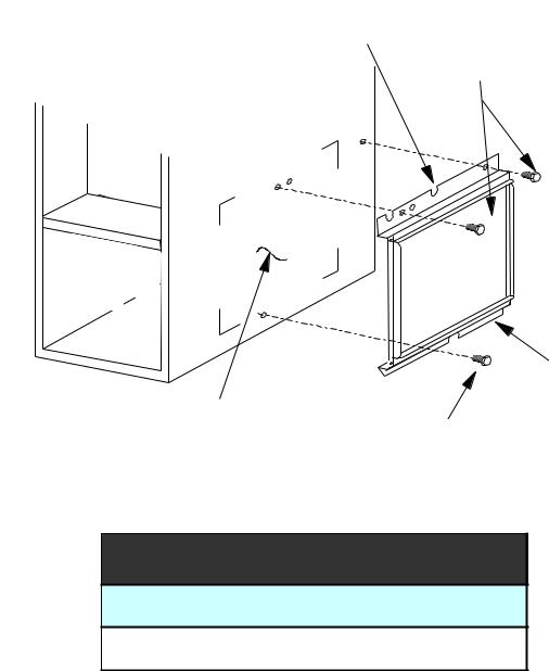
EXTERNAL FILTER RACK KIT (EFR01)
SLOTS IN FILTER
CLEAR SCREWS
ON UNIT
BLOWER DECK
SCREWS
UNIT SIDE
PANEL
FRONT |
|
|
|
OF UNIT |
|
|
|
|
|
FILTER RACK ASSEMBLY |
|
BASE |
|
(FACE FILTER OPENING |
|
|
TOWARDS FRONT |
||
OF UNIT |
|
||
RETURN AIR |
OF UNIT) |
||
|
|||
|
|
||
|
CUTOUT AREA |
LOWER EDGE |
|
|
|
||
|
|
SCREW |
EFR01 EXTERNAL FILTER RACK KIT
Used on Models
80% Upflow Model Furnaces
8
OPERATING INSTRUCTIONS
 FOR YOUR SAFETY READ BEFORE OPERATING
If you do not follow these instructions exactly, a fire or explosion may result causing property damage, personal injury or loss of life.
A. This appliance does not have a pilot. It is equipped with an ignition device which
automatically lights the burners. Do not try to light the burners by hand.
B. BEFORE OPERATING smell around the appliance area for gas. Be sure to smell next to the floor because some gas
is heavier than air and will settle on the floor.
WHAT TO DO IF YOU SMELL GAS Do not try to light any appliance.
 Do not touch any electric switch;
do not use any telephone in your building.
Immediately call your supplier
from a neighbor's phone. Follow the gas suppliers instructions.
 If you cannot reach your gas supplier, call the fire department.
C. Use only your hand to move the gas control switch or knob. Never use tools. If the gas control switch or knob will not operate, don't try to repair it,
call a qualified service technician. Force or attempted repair may result in
a fire or explosion.
D. Do not use this appliance if any part has been under water. Immediately call a qualified service technician to inspect
the appliance and to replace any part of the control system and any gas control which has been under water.
 OPERATING INSTRUCTIONS
1.STOP! Read the safety information above on this label.
2.Set the thermostat to lowest setting.
3.Turn off all electric power to the appliance.
4.This appliance is equipped with an automatic ignition system which automatically lights the burners. Do not
try to light the burners by hand.
5.Remove control access panel.
6.Move the gas control switch or knob to "OFF".
7. Wait five (5) minutes to clear out any gas. If you then smell gas, STOP! Follow "B" in the safety information above on this label. If you don't smell gas, go to the next step.
8.Move the gas control switch or knob to "ON".
9.Replace control access panel.
10.Turn on all electric power to the appliance.
11.Set the thermostat to the desired setting.
12.If the appliance will not operate, follow the instructions "To Turn Off Gas To Appliance" and call your service technician or gas supplier.
GAS CONTROL
SWITCH SHOWN
IN "ON" POSITION
 TO TURN OFF GAS TO APPLIANCE
4. Move the gas control switch or knob
to "OFF". Do not force. 5. Replace control access panel.
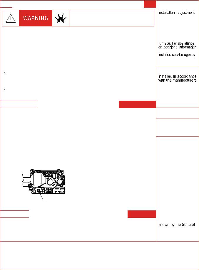
WARNING: Improper
alteration, service or maintenance can cause injury or property damage.
Refer to the user's information manual
provided with this
consult a qualified
or the gas supplier.
This furnace must be
instructions and local codes. In the absence of local codes, follow the National Fuel Gas
Code, ANSI Z223.1.
For indoor installation.
PGB & PGJ For outdoor
installation only.
WARNING: If not installed, operated
and maintained in accordance with the
manufacturer's instructions, this
product could expose you to substances in fuel combustion which can cause death or serious
illness and which are known to the
State of California to cause cancer, birth defects or other
reproductive harm. This product contains
fiberglass insulation.
Fiberglass insulation contains a chemical
California to cause cancer.
FOR YOUR SAFETY |
Do not store or use gasoline or |
other flammable vapors and liquids in the vicinity of this |
|
or any other appliance. |
0140F00001P |
9
OPERATING INSTRUCTIONS
CONSIGNES DE SECURITE - LIRE
AVANT D'ALLUMER L'APPAREIL
AVERTISSEMENT: Le non-respect des instructions qui suivent peut entrainer^ un risque d'incendie ou d'explosion causant des dommages, des blessures ou la mort.
A.Cet appareil comporte pas de veilleuse. Il est muni d'un mecanisme qui allume automatiquement le bruleur^ . N'allumez paz le bruleur^ manuellement.
B.Sentir tout autour de l'appariel AVANT D'ALLUMER afin de deceler toute fuite de gaz. Assurez-vous de sentir tout pres du plancher car certains gaz sont plus lourds que l'air et se deposeront sur le plancher.
SI VOUS SENTEZ UNE ODEUR DE GAZ:
Ne tentez d'allumer aucun appariel.
Ne touchez pas aux interrupteurs electriques; n'utiliser aucun telephone dans l'edifice ou vous vous trouvez.
Appelez immediatement votre fournisseur de gaz en utilisant le telephone d'un voisin et suivez les instructions du fournisseur.
Appelez les pompiers si vous ne parvenez pas a rejoindre votre fournisseur de gaz.
C. N'utiliser que votre main pour pousser ou tourner le commande du gaz. N'utilisez jamais d'outils. Si vous ne parvenez pas a pousser ou a tourner la commande, ne tentez pas de la reparer; appelez un reparateur qualifie. Forcer la commande ou essayer de la reparer peut entrainer^ un risque d'incendie ou d'explosion.
D. N'utilisez pas cet appareil si l'une de ses parties a ete dans l'eau. Si cela se produit, demandez immediatement a un reparateur qualifie d'inspecter l'appareil et de remplacer toute piece du systeme de controle^ et toute commande de gaz ayant ete dans l'eau.
0140F00002P
 INSTRUCTIONS DE SERVICE
1. UN INSTANT! Lisez d'abord les consignes de securite ci-dessus.
2. Reglez le thermostat a son point le plus bas. 3. Coupez l'alimentation electrique de l'appareil. 4. Cet appareil est muni d'un mecanisme qui
allume automatiquement le bruleur^ . Ne tentez pas d'allumer le bruleur^ manuellement.
5. Retirez le panneau d'acces de la commande.
6. Mettez la commande de gaz a la position
^
ARRET ("OFF").
7. Attendez cinq (5) minutes afin de permettre a
tout gaz present d'etre^ evacue. Si vous sentez
^
une odeur de gaz a ce moment, ARRETEZ! et suivez les consignes de securite donnees au paragraphe B ci-dessus. Si vous ne sentez pas de gaz, passez a l'etape suivante.
8.Mettez la commande de gaz a la position MARCHE ("ON").
9.Remettez la panneau d'acces de la commande en place.
10.Retablissez l'alimenation electrique de l'appareil.
11.Reglez le thermostat a le temperature desiree.
12.Si l'appareil ne fonctionne pas, suivez les instructions intitulees "Arret^ du gaz" et appelez un reparateur qualifie ou votre fournisseur de gaz.
Commande de gaz en position
"MARCHE"
^
ARRET DU GAZ
1.Reglez le thermostat a son point le plus bas.
2.Coupez l'alimentation electrique de l'appareil si vous devez effectuer un entretien.
3.Retirez le panneau d'acces de la commande. ^
4.Mettez la commande de gaz a la position ARRET ("OFF").
5.Remettez le panneau d'acces de la commande en place.
10
PRODUCT DESIGN
Safety
Please adhere to the following warnings and cautions when installing, adjusting, altering, servicing, or operating the furnace.
 WARNING
TO PREVENT PERSONAL INJURY OR DEATH DUE TO IMPROPER INSTALLATION, ADJUSTMENT, ALTERATION, SERVICE OR MAINTENANCE, REFER TO THIS MANUAL. FOR ADDITIONAL ASSISTANCE OR INFORMATION, CONSULT A QUALIFIED INSTALLER, SERVICE AGENCY OR THE GAS SUPPLIER.
 WARNING
THIS PRODUCT CONTAINS OR PRODUCES A CHEMICAL OR CHEMICALS WHICH MAY CAUSE SERIOUS ILLNESS OR DEATH AND WHICH ARE KNOWN TO THE STATE OF CALIFORNIA TO CAUSE CANCER, BIRTH DEFECTS OR OTHER REPRODUCTIVE HARM.
 WARNING
TO PREVENT POSSIBLE PROPERTY DAMAGE, PERSONAL INJURY OR DEATH DUE TO ELECTRICAL SHOCK, THE FURNACE MUST BE LOCATED TO PROTECT THE ELECTRICAL COMPONENTS FROM WATER.
Charge (ESD) Precautions
NOTE: Discharge body’s static electricity before touching unit. An electrostatic discharge can adversely affect electrical components.
Use the following precautions during furnace installation and servicing to protect the integrated control module from damage. By putting the furnace, the control, and the person at the same electrostatic potential, these steps will help avoid exposing the integrated control module to electrostatic discharge. This procedure is applicable to both installed and uninstalled (ungrounded) furnaces.
1.Disconnect all power to the furnace. Do not touch the integrated control module or any wire connected to the control prior to discharging your body’s electrostatic charge to ground.
2.Firmly touch a clean, unpainted, metal surface of the furnace near the control. Any tools held in a person’s hand during grounding will be discharged.
3.Service integrated control module or connecting wiring following the discharge process in Step 2. Use caution not to recharge your body with static electricity; (i.e., do not move or shuffle your feet, do not touch ungrounded objects, etc.). If you come in contact with an ungrounded object, repeat Step 2 before touching control or wires.
4.Discharge any static electricity from your body to ground before removing a new control from its container. Follow Steps 1 through 3 if installing the control on a furnace. Return any old or new controls to their containers before touching any ungrounded object.
Product Application
This product is designed for use as a residential home gas furnace. It is not designed or certified for use in mobile home, trailer, or recreational vehicle applications.
This furnace can be used in the following non-industrial commercial applications: Schools, Office buildings, Churches,
Retail stores, Nursing homes, Hotels/motels, Common or office areas. In such applications, the furnace must be installed with the installation instructions.
The GME8 and AMEH8 furnaces are ETL certified appliances and are appropriate for use with natural or propane gas. (NOTE: If using propane gas, a propane conversion kit is required).
IMPORTANT NOTE: The 80% furnace cannot be installed as a direct vent (i.e., sealed combustion) furnace. The burner box is present only to help reduce sound transmission from the burners to the occupied space.
To ensure proper installation, operation and servicing, thoroughly read the installation and service manuals for specifics pertaining to the installation, servicing and application of this product.
 WARNING
POSSIBLE PROPERTY DAMAGE, PERSONAL INJURY OR DEATH DUE TO FIRE, EXPLOSION, SMOKE, SOOT, CONDENSTAION, ELECTRICAL SHOCK OR CARBON MONOXIDE MAY RESULT FROM IMPROPER INSTALLATION, REPAIR, OPERATION, OR MAINTENANCE OF THIS PRODUCT.
 WARNING
TO PREVENT PROPERTY DAMAGE, PERSONAL INJURY OR DEATH DUE TO FIRE, DO NOT INSTALL THIS FURNACE IN A MOBILE HOME, TRAILER, OR RECREATIONAL VEHICLE.
To ensure proper furnace operation, install, operate, maintain and service the furnace in accordance with the installation, operation and service instructions, all local building codes and ordinances. In their absence, follow the latest edition of the National Fuel Gas Code (NFPA 54/ANSI Z223.1), and/or CAN/CGA B149 Installation Codes, local plumbing or waste water codes, and other applicable codes.
A copy of the National Fuel Gas Code (NFPA 54/ANSI Z223.1) can be obtained from any of the following:
American National Standards Institute 1430 Broadway
New York, NY 10018
National Fire Protection Association
1 Batterymarch Park
Quincy, MA 02269
CSA International
8501 East Pleasant Valley
Cleveland, OH 44131
11
PRODUCT DESIGN
A copy of the CAN/CGA B149 Installation Codes can be obtained from:
CSA International
178 Rexdale Boulevard
Etobicoke, Ontario, Canada M9W, 1R3
The rated heating capacity of the furnace should be greater than or equal to the total heat loss of the area to be heated. The total heat loss should be calculated by an approved method or in accordance with “ASHRAE Guide” or “Manual J-Load Calculations” published by the Air Conditioning Contractors of America.
Location Requirements and Considerations
 WARNING
TO PREVENT POSSIBLE EQUIPMENT DAMAGE, PROPERTY DAMAGE, PERSONAL INJURY OR DEATH, THE FOLLOWING BULLET POINTS MUST BE OBSERVED WHEN INSTALLING THE UNIT.
Follow the instructions listed below when selecting a furnace location. Refer also to the guidelines provided in the
Combustion and Ventilation Air Requirements section in this manual or the installation instructions for details.
•Centrally locate the furnace with respect to the proposed or existing air distribution system.
•Ensure the temperature of the return air entering the furnace is between 55°F and 100°F when the furnace is heating.
•Provide provisions for venting combustion products outdoors through a proper venting system. Special consideration should be given to vent/flue pipe routing and combustion air intake pipe when applicable.
80% Furnaces: All installations must be vented in accordance with National Fuel Gas Code, NFPA 54/ ANSI Z223.1 - lateset edition. In Canada the furnaces must be vented in accordance with the National Standard of Canada, CAN/CGA B149.
•Ensure upflow or horizontal furnaces are not installed directly on carpeting, or any other combustible material. The only combustible material allowed is wood.
•Exposure to contaminated combustion air will result in safety and performance-related problems. Do not install the furnace where the combustion air is exposed to the following substances:
chlorinated waxes or cleaners chlorine-based swimming pool chemicals water softening chemicals
deicing salts or chemicals carbon tetrachloride halogen type refrigerants
cleaning solutions (such as perchloroethylene)
printing inks paint removers varnishes hydrochloric acid
cements and glues
antistatic fabric softeners for clothes dryers and masonry acid washing materials
•Seal off a non-direct vent furnace if it is installed near an area frequently contaminated by any of the above substances. This protects the non-direct vent furnace from airborne contaminants. To ensure that the enclosed non-direct vent furnace has an adequate supply of combustion air, vent from a nearby uncontaminated room or from outdoors. Refer to the Combustion and Ventilation Air Requirements section in this manual or the installation instructions for details.
•If the furnace is used in connection with a cooling unit, install the furnace upstream or in parallel with the cooling unit coil. Premature heat exchanger failure will result if the cooling unit coil is placed ahead of the furnace.
•If the furnace is installed in a residential garage, position the furnace so that the burners and ignition source are located not less than 18 inches (457 mm) above the floor. Protect the furnace from physical damage by vehicles.
•If the furnace is installed horizontally, the furnace access doors must be vertical so that the burners fire horizontally into the heat exchanger. Do not install the unit with the access doors on the “up/top” or “down/ bottom” side of the furnace.
Clearances and Accessibility
Installations must adhere to the clearances to combustible materials to which this furnace has been design certified. The minimum clearance information for this furnace is provided on the unit’s clearance label. These clearances must be permanently maintained. Refer to Specification Sheet for minimum clearances to combustible materials. Clearances must also accommodate an installation’s gas, electrical, and drain trap and drain line connections. NOTE: In addition to the required clearances to combustible materials, a minimum of 24 inches service clearance must be available in front of the unit.
A furnace installed in a confined space (i.e., a closet or utility room) must have two ventilation openings with a total minimum free area of 0.25 square inches per 1,000 BTU/hr of furnace input rating. One of the ventilation openings must be within 12 inches of the top; the other opening must be within 12 inches of the bottom of the confined space. In a typical construction, the clearance between the door and door frame is usually adequate to satisfy this ventilation requirement.
12
PRODUCT DESIGN
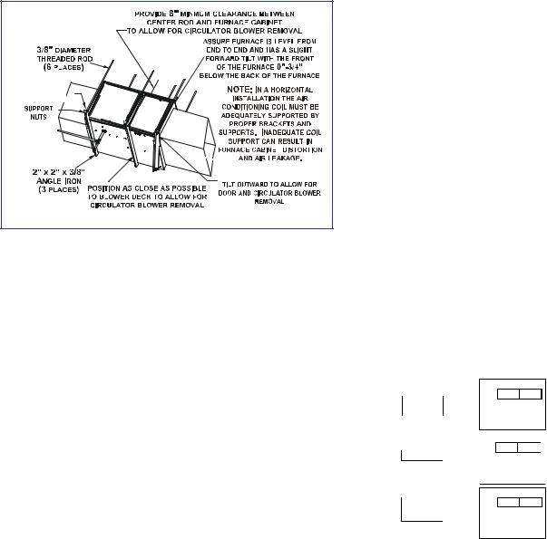
Furnace Suspension
If suspending the furnace from rafters or joist, use 3/8" threaded rod and 2”x2”x1/8” angle iron as shown in the following figure. If the furnace is installed in a crawl space it must also be suspended from the floor joist or supported by a concrete pad. Never install the furnace on the ground or allow it to be exposed to water. The length of rod will depend on the application and the clearances necessary.
Suspended Furnace |
EXISTING FURNACE REMOVAL
NOTE: When an existing furnace is removed from a venting system serving other appliances, the venting system may be too large to properly vent the remaining attached appliances.
The following vent testing procedure is reproduced from the
American National Standard/National Standard of Canada for Gas-Fired Central Furnaces ANSI Z21.47, latest edition, CSA-2.3b, latest edition Section 1.23.1.
The following steps shall be followed with each appliance connected to the venting system placed in operation, while any other appliances connected to the venting system are not in operation:
a.Seal any unused openings in the venting system;
b.Inspecttheventingsystemforpropersizeandhorizontal pitch, as required by the National Fuel Gas Code, ANSI Z223.1 or the CSA B149 Installation Codes and these instructions. Determine that there is no blockage or restriction, leakage, corrosion and other deficiencies which could cause an unsafe condition;
c.In so far as practical, close all building doors and windows and all doors between the space in which the appliance(s) connected to the venting system are located and other spaces of the building. Turn on clothes dryers and any appliance not connected to the venting system. Turn on any exhaust fans, such as range hoods and bathroom exhausts, so they shall operate at maximum speed. Do not operate a summer exhaust fan. Close fireplace dampers;
d.Follow the lighting instructions. Place the appliance being inspected in operation. Adjust thermostat so appliance shall operate continuously;
e.Test for draft hood equipped spillage at the draft hood reliefopeningafter5minutesofmainburneroperation. Use the flame of a match or candle;
f.After it has been determined that each appliance connected to the venting system properly vents when tested as outlined above, return doors, windows, exhaust fans, fireplace dampers and any other gas burning appliance to their previous conditions of use;
g.If improper venting isobserved duringany of the above tests, the common venting system must be corrected.
Corrections must be in accordance with the latest edition of the National Fuel Gas Code NFPA 54/ANSI Z223.1 and/or CSA B149 Installation Codes.
If resizing is required on any portion of the venting system, use the appropriate table in Appendix G in the latest edition of the National Fuel Gas Code ANSI Z223.1 and/or CSA B149
Installation Codes.
Thermostat Requirements
To use a single-stage thermostat, turn off power to the furnace, move the thermostat selection DIP switch to the OFF position. Set the desired transition time by setting the transition delay DIP switch to the desired ON/OFF position. Turn power back on.
NOTE: The GME8 and AMEH8 hybrid furnaces require a single stage thermostat. These furnaces utilize a control board with single stage or two stage capability. The second stage feature is established by setting a dip switch on the board, either one stage or two stage. All of the second stage timing is then controlled by dipswitch 3 on the circuit board.
|
100 |
1 |
|
|
|
|
|
150 |
HEAT OFF SECOND |
|
|
|
FOF |
|
NO |
SECOND |
|
DELAY |
DELAY |
|
|
|
|
DELAY |
||
|
|
|
|
|
|
|||
MODE |
2-STAGE |
2 |
|
|
|
|
|
1-STAGE |
|
|
|
|
|
||||
|
|
FFO |
|
NO |
||||
|
|
|
|
|
|
|||
SECOND |
5 |
3 |
|
|
|
|
|
|
|
|
|
|
|
|
|||
STAGE |
|
FFO |
|
NO |
AUTO |
|||
MINUTES |
|
|
|
|||||
ONLY |
|
|
|
|
|
|||
|
|
|
|
|
|
|
|
|
In an area having good air circulation, locate the thermostat about five feet high on a vibration-free inside wall. Do not install the thermostat where it may be influenced by any of the following:
•Drafts, or dead spots behind doors, in corners, or under cabinets.
•Hot or cold air from registers.
•Radiant heat from the sun.
•Light fixtures or other appliances.
13
PRODUCT DESIGN
•Radiant heat from a fireplace.
•Concealed hot or cold water pipes, or chimneys.
•Unconditioned areas behind the thermostat and dehumidistat, such as an outside wall.
Consult the instructions packaged with the thermostat and dehumidistat for mounting instructions and further precautions.
COMBUSTION AND VENTILATION AIR REQUIREMENTS
 WARNING
POSSIBLE PROPERTY DAMAGE, PERSONAL INJURY OR DEATH MAY OCCUR IF THE FURNACE IS NOT PROVIDED WITH ENOUGH FRESH AIR FOR PROPER COMBUSTION AND VENTILATION OF FLUE GASES. MOST HOMES REQUIRE OUTSIDE AIR BE SUPPLIED TO THE FURNACE AREA.
Improved construction and additional insulation in buildings have reduced heat loss by reducing air infiltration and escape around doors and windows. These changes have helped in reducing heating/cooling costs but have created a problem supplying combustion and ventilation air for gas fired and other fuel burning appliances. Appliances that pull air out of the house (clothes dryers, exhaust fans, fireplaces, etc.) increase the problem by starving appliances for air.
If this furnace is to be installed in the same space with other gas appliances, such as a water heater, ensure there is an adequate supply of combustion and ventilation air for the other appliances. Refer to the latest edition of the National Fuel Gas Code NFPA 54/ANSI Z223.1 (Section 9.3), or CAN/ CGA B149 Installation Codes (Sections 7.2, 7.3, or 7.4), or applicable provisions of the local building codes for determining the combustion air requirements for the appliances.
Most homes will require outside air be supplied to the furnace area by means of ventilation grilles or ducts connecting directly to the outdoors or spaces open to the outdoors such as attics or crawl spaces.
The following information on air for combustion and ventilation is reproduced from the National Fuel Gas Code NFPA
54/ANSI Z223.1 Section 9.3.
9.3* Air for Combustion and Ventilation.
9.3.1 General.
9.3.1.1 Air for combustion, ventilation, and dilution of flue gases for appliances installed in buildings shall be obtained by application of one of the methods covered in 9.3.2 through 9.3.6. Where the requirements of 9.3.2 are not met, outdoor air shall be introduced in accordance with methods covered in 9.3.3 through 9.3.6.
Exception No. 1: This provision shall not apply to direct vent appliances.
9.3.1.2Appliances of other than natural draft design and other than Category 1 vented appliances shall be provided with combustion, ventilation, and dilution air in accordance with the appliance manufacturer’s instructions.
9.3.1.3Appliances shall be located so as not to interfere with proper circulation of combustion, ventilation, and dilution air.
9.3.1.4Where used, a draft hood or a barometric draft regulator shall be installed in the same room or enclosure as the appliance served so as to prevent any difference in pressure between the hood or regulator and the combustion air supply.
9.3.1.5Makeup air requirements for the operation of exhaust fans, kitchen ventilation systems, clothes dryers, and fireplaces shall be considered in determining the adequacy of a space to provide combustion air requirements.
9.3.2 Indoor Combustion Air. The required volume of indoor air shall be determined in accordance with the method in 9.3.2.1 or 9.3.2.2 except that where the air infiltration rate is known to be less than 0.40 ACH, the method in 9.3.2.2 shall be used. The total required volume shall be the sum of the required volume calculated for all appliances located within the space. Rooms communicating directly with the space in which the appliances are installed through openings not furnished with doors, and through combustion air openings sized and located in accordance with 9.3.2.3, are considered a part of the required volume.
9.3.2.1* Standard Method. The minimum required volume shall be 50 ft 3 per 1,000/Btu/hour (4.8m3/kW).
9.3.2.2* Known Air Infiltration Rate Method. Where the air infiltration rate of a structure is known, the minimum required volume shall be determined as follows:
(1) For appliances other than fan-assisted, calculate using the following equation:
21 ft3 |
I |
|
Required Volume other > ________ |
|
other |
|
|
|
ACH |
(1000 Btu/hr) |
|
(2)For fan-assisted appliances, calculate using the following equation:
|
Required Volume fan |
15 ft3 |
I fan |
|||
|
> ________ |
(1000 Btu/hr) |
||||
where: |
|
|
ACH |
|||
= |
all appliances other than fan-assisted input in Btu |
|||||
I |
other |
|||||
|
|
|
per hour |
|
|
|
I |
fan |
= |
fan-assisted appliances input in Btu per hour |
|||
ACH |
= |
air change per hour (percent of volume of space |
||||
|
|
|
exchanged per hour, expressed as a decimal) |
|||
(3)For purposes of this calculation, an infiltration rate greater than 0.60 ACH shall not be used in the equations in 9.3.2.2(1) and 9.3.2.2(2).
14
PRODUCT DESIGN
9.3.2.3 Indoor Opening Size and Location. Openings used to connect indoor spaces shall be sized and located in accordance with the following:
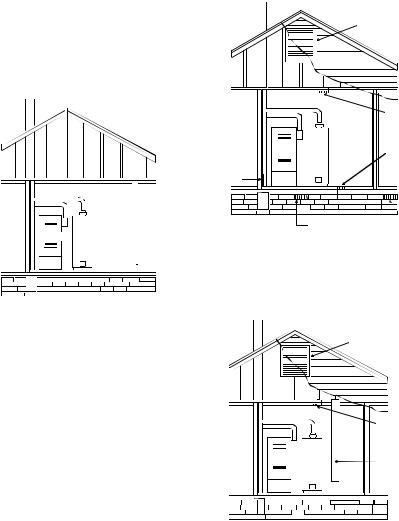
(1)*Combining spaces on the same story. Each opening shall have a minimum free area of 1 in.2/1000Btu/hr (2200 mm2/ kW) of the total input rating of all appliances in the space but not less than 100 in.2 (0.60m2). One opening shall commence within 12 in. (300 mm) of the top, and one opening shall commence within 12 in. (300 mm) of the bottom, of the enclosure [see Figure A.9.3.2.3(1)]. The minimum dimension of air openings shall be not less than 3 in. (80 mm).
 Chimney or Gas Vent
NOTE: Each opening must have a free area of not less than one square inch per 1000 BTU of
the total input rating of all equipment in the enclosure, but not less than 100 square inches.
 Opening
Water
Furnace Heater
 Opening
Figure A.9.2.3.3.(1) All Combustion Air from Adjacent Indoor Spaces through Indoor Combustion Air
Openings.
(2)Combining spaces in different stories. The volumes of spaces in different stories shall be considered as communicating spaces where such spaces are connected by one or more openings in doors or floors having a total minimum free area of 2 in.2/1000 Btu/hr (4400 mm2/kW) of total input rating of all appliances.
9.3.3 Outdoor Combustion Air. Outdoor combustion air shall be provided through opening(s) to the outdoors in accordance with the methods in 9.3.3.1 or 9.3.3.2. The minimum dimension of air openings shall not be less than 3 in. (80 mm).
9.3.3.1 Two Permanent Openings Method. Two permanent openings, one commencing within 12 in. (300 mm) of the top and one commencing within 12 in. (300 mm) of the bottom, of the enclosure shall be provided. The openings shall communicate directly, or by ducts, with the outdoors or spaces that freely communicate with the outdoors, as follows:
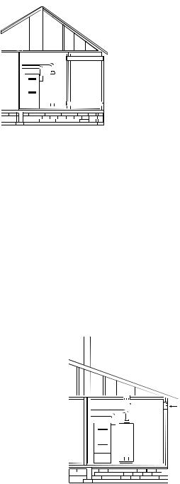
(1)*Where directly communicating with the outdoors or where communicating to the outdoors through vertical ducts, each opening shall have a minimum free area of 1 in.2/ 4000 Btu/hr (550 min2/kW) of total input rating of all appliances in the enclosure. [See Figure A.9.3.3.1(1)(a) and Figure A.9.3.3.1(1)(b).]
 Chimney or Gas Vent
Ventilation louvers (each end of attic)
NOTE: The inlet and outlet air openings must each have a free area of not less than one square inch per 4000 BTU of the
total input rating of all equipment in the enclosure.
|
|
|
|
|
Outlet Air |
|
|
|
|
|
|
|
|
|
|
|
|
|
|
|
|
|
|
Water |
|||
|
|
|
Heater |
|
|
|
Furnace |
Inlet Air |
|||||
|
|
|
||||
|
|
|
|
|
||
Alternate air inlet
Ventilation louvers for unheated crawl space
Figure A.9.3.3.1(1)(a) All Combustion Air From Outdoors - Inlet Air from Ventilated Crawl Space and Outlet Air to Ventilated Attic.
 Chimney or Gas Vent
Ventilation louvers (each end of attic)
NOTE: The inlet and outlet air openings must each have a free area of not less than one square inch per 4000 BTU of the
total input rating of all equipment in the enclosure.
|
|
|
|
|
|
|
|
|
|
|
|
|
|
|
|
Outlet Air |
|
|
|
|
|
|
|
|
|
|
|
|
|
|
|
|
|
|
|
|
|
|
|
|
|
|
|
|
|
|
|
|
|
|
|
|
|
|
|
|
|
|
|
|
|
|
|
|
Water |
|
|||||
|
|
|
|
|
|
|
|
|
|
|
Heater |
|
|
|
|
|
|
|
|
|
|
|
|
|
|
|
|
|
|
|
|
|
|
||
|
|
|
|
Furnace |
Inlet air duct |
||||||||||||
|
|
|
|
|
|
|
|
|
|
|
|
||||||
|
|
|
|
|
|
|
|
|
|
|
|
|
|
|
|
||
|
|
|
|
|
|
|
|
|
|
|
|
|
|
|
|
[ends 1 ft (300 mm) |
|
|
|
|
|
|
|
|
|
|
|
|
|
|
|
|
|
above floor] |
|
|
|
|
|
|
|
|
|
|
|
|
|
|
|
|
|
|
|
|
|
|
|
|
|
|
|
|
|
|
|
|
|
|
|
|
|
|
|
|
|
|
|
|
|
|
|
|
|
|
|
|
|
|
|
|
|
|
|
|
|
|
|
|
|
|
|
|
|
|
|
|
|
|
|
|
|
|
|
|
|
|
|
|
|
|
|
|
|
|
|
|
|
|
|
|
|
|
|
|
|
|
|
|
|
|
|
|
|
Figure A.9.3.3.1(1)(b) All Combustion Air
From Outdoors through Ventilated Attic.
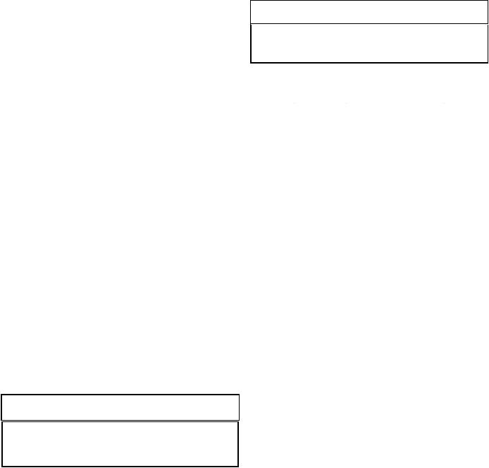
(2)*Where communicating with the outdoors through horizontal ducts, each opening shall have a minimum free area of 1 in.2/2000 Btu/hr (1100 min2/kW) of total input rating of all appliances in the enclosure. [See Figure A.9.3.3.1(2).]
15
PRODUCT DESIGN
 Chimney or Gas Vent
|
|
|
|
|
|
|
|
|
|
|
|
|
|
|
NOTE: The air duct openings |
|
|
|
|
|
|
|
|
|
|
|
|
|
|
|
must have a free area of not |
|
|
|
|
|
|
|
|
|
|
|
|
|
|
|
less than one square inch per |
|
|
|
|
|
|
|
|
|
|
|
|
|
|
|
2000 BTU of the total input |
|
|
|
|
|
|
|
|
|
|
|
|
|
|
|
rating of all equipment in the |
|
|
|
|
|
|
|
|
|
|
|
Outlet air duct |
|
enclosure*. |
||
|
|
|
|
|
|
|
|
|
|
|
|
|
|||
|
|
|
|
|
|
|
|
|
|
|
|
|
|
|
|
|
|
|
|
|
|
|
|
|
|
|
|
|
|
|
|
|
|
|
|
|
|
|
|
Water |
|
|
|||||
|
|
|
|
|
|
|
|
|
|||||||
|
|
|
|
|
|
|
|
Heater |
|
|
|
|
|
|
|
|
|
|
|
Furnace |
Inlet air duct |
|
|
||||||||
|
|
|
|
|
|
|
|
|
|
|
|||||
|
|
|
|
|
|
|
|
|
|
|
|
|
|
||
|
|
|
|
|
|
|
|
|
|
|
|
|
|
||
|
|
|
|
|
|
|
|
|
|
|
|
|
|
|
|
|
|
|
|
|
|
|
|
|
|
|
|
|
|
|
|
|
|
|
|
|
|
|
|
|
|
|
|
|
|
|
|
|
|
|
|
|
|
|
|
|
|
|
|
|
|
|
|
|
|
|
|
|
|
|
|
|
|
|
|
|
|
|
|
|
|
|
|
|
|
|
|
|
|
|
|
|
|
|
|
|
|
|
|
|
|
|
|
|
|
|
|
|
|
|
|
|
|
|
|
|
|
|
|
|
|
|
|
|
|
|
|
Figure A.9.3.3.1(2) All Combustion Air From Outdoors
through Horizontal Ducts.
9.3.3.2* One Permanent Opening Method. One permanent openings, commencing within 12 in. (300 mm) of the top of the enclosure, shall be provided. The appliance shall have clearances of at least 1 in. (25 mm) from the sides and back and 6 in. (150 mm) from the front of the appliance. The opening shall directly communicate with the outdoors or shall communicate through a vertical or horizontal duct to the outdoors or spaces that freely communicate with the outdoors (see Figure A.9.3.3.2) and shall have a minimum free area of the following:
(1)1 in.2/3000 Btu/hr (700 mm2 per kW) of the total input rating of all appliances located in the enclosure, and
(2)Not less than the sum of the areas of all vent connectors in the space.
NOTE: The single opening must have
a free area of not less than one  Chimney or Gas Vent square inch per 3000 BTU of
the total input rating of all equip-
ment in the enclosure, but not less than the sum of the areas of all vent connectors in the confined space.
|
|
|
|
|
|
|
|
|
|
|
|
|
|
Opening |
|
|
|
|
|
|
|
|
|
|
|
|
|
|
Alternate |
|
|
|
|
|
|
|
|
|
|
|
|
|
||
|
|
|
|
|
|
|
|
|
|
Water |
|
|
||
|
|
|
|
|
|
|
|
|
|
|
|
|
Opening |
|
|
|
|
|
|
|
|
|
|
|
Heater |
|
|
||
|
|
|
|
|
|
|
|
|
|
|
|
Location |
||
|
|
|
|
|
Furnace |
|
|
|||||||
|
|
|
|
|
|
|
|
|
|
|
||||
|
|
|
|
|
|
|
|
|
|
|
|
|
|
|
|
|
|
|
|
|
|
|
|
|
|
|
|
|
|
|
|
|
|
|
|
|
|
|
|
|
|
|
|
|
|
|
|
|
|
|
|
|
|
|
|
|
|
|
|
|
|
|
|
|
|
|
|
|
|
|
|
|
|
|
|
|
|
|
|
|
|
|
|
|
|
|
|
|
|
Figure A.9.3.3.2 All Combustion Air From Outdoors through Single Combustion Air
Opening.
9.3.4 Combination Indoor and Outdoor Combustion Air.
The use of a combination of indoor and outdoor combustion air shall be in accordance with (1) through (3) (see example calculation in Annex J]:
(1)Indoor Openings: Where used, openings connecting the interior spaces shall comply with 9.3.2.3.
(2)Outdoor Opening(s) Location. Outdoor opening(s) shall be located in accordance with 9.3.3.
(3)Outdoor Opening(s) Size. The outdoor opening(s) size shall be calculated in accordance with the following:
(a)The ratio of the interior spaces shall be the available volume of all communicating spaces divided by the required volume.
(b)The outdoor size reduction factor shall be 1 minus the ratio of interior spaces.
(c)The minimum size of outdoor opening(s) shall be the full size of outdoor opening(s) calculated in accordance with 9.3.3, multiplied by the reduction factor. The minimum dimension of air openings shall not be less than 3 in. (80 mm).
9.3.5Engineered Installations. Engineered combustion air installations shall provide an adequate supply of combustion, ventilation, and dilution air and shall be approved by the authority having jurisdiction.
9.3.6Mechanical Combustion Air Supply. Where all combustion air is provided by a mechanical air supply system, the combustion air shall be supplied form outdoors at the minimum rate of 0.35 ft3/min per 1000 Btu/hr (0.034 m3/min per kW) for all appliances located within the space.
9.3.6.1Where exhaust fans are installed, additional air shall be provided to replace the exhausted air.
9.3.6.2Each of the appliances served shall be interlocked to the mechanical air supply system to prevent main burner operation where the mechanical air supply system is not in operation.
9.3.6.3Where combustion air is provided by the building’s mechanical ventilation system, the system shall provide the specified combustion air rate in addition to the required ventilation air.
9.3.7 Louvers, Grilles, and Screens.
9.3.7.1Louvers and Grilles. The required size of openings for combustion, ventilation, and dilution air shall be based on the net free area of each opening. Where the free area through a design of louver or grille or screen is known, it shall be used in calculating the size opening required to provide the free area specified. Where the louver and grille design and free area are not known, it shall be assumed that wood louvers will have 25 percent free area, and metal louvers and grilles will have 75 percent free area. Nonmotorized louvers and grilles shall be fixed in the open position.
9.3.7.2Minimum Scree Mesh Size. Screens shall not be smaller than 1/4 in. mesh.
9.3.7.3Motorized Louvers. Motorized louvers shall be interlocked with the appliance so they are proven in the full open position prior to main burner ignition and during main
16
PRODUCT DESIGN
burner operation. Means shall be provided to prevent the main burner form igniting should the louver fail to open during burner startup and to shut down the main burner if the louvers close during burner operation.
9.3.8 Combustion Air Ducts. Combustion air ducts shall comply with 9.3.8.1 through 9.3.8.8.
9.3.8.1 Ducts shall be constructed of galvanized steel or a material having equivalent corrosion resistance, strength, and rigidity.
Exception: Within dwellings units, unobstructed stud and joist spaces shall not be prohibited from conveying combustion air, provided that not more than one fireblock is removed.
9.3.8.2Ducts shall terminate in an unobstructed space, allowing free movement of combustion air to the appliances.
9.3.8.3Ducts shall serve a single space.
9.3.8.4Ducts shall not serve both upper and lower combustion air openings where both such openings are used. The separation between ducts servicing upper and lower combustion air openings shall be maintained to the source of combustion air.
9.3.8.5Ducts shall not be screened where terminating in an attic space.
9.3.8.6Horizontal upper combustion air ducts shall not slope downward toward the source of combustion air.
9.3.8.7The remaining space surrounding a chimney liner, gas vent, special gas vent, or plastic piping installed within a masonry, metal, or factory built chimney shall not be used to supply combustion air.
Exception: Direct vent appliances designed for installation in a solid fuel-burning fireplace where installed in accordance with the manufacture’s installation instructions.
9.3.8.8 Combustion air intake openings located on the exterior of the building shall have the lowest side of the combustion air intake openings located at least 12 in. (300 mm) vertically from the adjoining grade level.
Category I Venting (Vertical Venting)
(80% Furnaces Only)
 WARNING
TO PREVENT POSSIBLE PERSONAL INJURY OR DEATH DUE TO ASPHYXIATION, NON-CONDENSING GAS FIRED WARM AIR FURNACES MUST BE CATEGORY I VENTED. DO NOT VENT ANY OF THESE FURNACES USING CATEGORY III VENTING.
Category I Venting is venting at a non-positive pressure. A furnace vented as Category I is considered a fan-assisted appliance and does not have to be "gas tight." NOTE: SingleStage and Two-Stage gas furnaces with induced draft blowers draw products of combustion through a heat exchanger allowing in some instances common venting with natural draft appliances (i.e. water heaters).
All installations must be vented in accordance with National Fuel Gas Code NFPA 54/ANSI Z223.1 - latest edition. In Canada, the furnaces must be vented in accordance with the National Standard of Canada, CAN/CGA B149.1 and CAN/CGA B149.2 - latest editions and amendments.
NOTE: The vertical height of the Category I venting system must be at least as great as the horizontal length of the venting system.
 WARNING
TO PREVENT POSSIBLE DEATH OR PERSONAL INJURY DUE TO ASPHYXIATION, COMMON VENTING WITH OTHER MANUFACTURER'S INDUCED DRAFT APPLIANCES IS NOT ALLOWED.
The minimum vent diameter for the Category I venting system is as shown in the following chart:
|
|
|
|
|
MODEL |
MINIMUM VENT |
|
|
UPFLOW |
|
|
|
|
|
|
|
60 |
4 Inch |
|
|
80 |
4 Inch |
|
|
100 |
5 Inch |
|
|
|
|
|
Under some conditions, larger vents than those shown above may be required or allowed.
When an existing furnace is removed from a venting system serving other appliances, the venting system may be too large to properly vent the remaining attached appliances. For complete details refer to Exisiting Furnace Removal section of this manual.
When resizing any portion of the common venting system, use the appropriate table in Appendix G in the latest edition of the National Fuel Gas Code NFPA 54/ANSI Z223.1.
Upflow or Horizontal units are shipped with the induced draft blower discharging from the top of the furnace ("Top" is as viewed for an upflow installation). The induced draft blower can be rotated 90 degrees for Category I venting. Refer to the following figure. For horizontal installations, a four inch single wall pipe can be used to extend the induced draft blower outlet 1/2” beyond the furnace cabinet. Vent the furnace in accordance with the National Fuel Gas Code NFPA 54/ANSI Z223.1 - latest edition. In Canada, vent the furnace in accordance with the National Standard of Canada, CAN/ CGA B149.1 and CAN/CGA B149.2 - latest editions and amendments.
NOTE: This furnace is not design certified to be horizontally vented.
17
 Loading...