


 Loading...
Installation, Operation,
and Maintenance Manual
Pathfinder®
Air-cooled Screw Chillers
Model AWS
170 to 550 Tons (600 to 1935 kW) 60Hz
164 to 604 Tons (575 to 2125 kW) 50Hz HFC-134a Refrigerant
IOM 1202-2
Group: Chiller
Part Number: IOM1202-2
Date: May 2015
|
|
|
Table of Contents |
Introduction . . . . . . . . . . . . . . . . . . . . . . . . . . . . . . . |
. . . 3 |
Circuit Functions . . . . . . . . . . . . . . . . . . . . . |
. 126. . . . . |
Installation and Startup . . . . . . . . . . . . . . . . . . . . . |
. . . 4 |
Alarms and Events . . . . . . . . . . . . . . . . . . . . . . . . |
. . 137 |
Lifting and Mounting Information . . . . . . . . . . . . . |
. . 16 |
Using the Controller . . . . . . . . . . . . . . . . . . . . . . . . |
. 145 |
Isolator Information . . . . . . . . . . . . . . . . . . . . . . |
. .50. |
. Optional Remote User Interface . . . . . . . . . . . . |
. .148. |
Electrical Information . . . . . . . . . . . . . . . . . . . . . . . |
. . 59 |
Optional Compressor VFD . . . . . . . . . . . . . . . . . . . |
. 150 |
Pressure Drop Data . . . . . . . . . . . . . . . . . . . . |
. .82. |
. . . Startup and Shutdown . . . . . . . . . . . . . . . . . . . . . . |
. 154 |
Controller Operation . . . . . . . . . . . . . . . . |
. .94. |
. . System. . . . Maintenance . . . . . . . . . . . . . . . . . . . |
. 156. . . . |
Sequence of Operation . . . . . . . . . . . . . . . . |
.108. . . . .Appendix . . . . . . . . . . . . . . . . . . . . . . . . . . . . . . . . . |
. 160 |
|
Unit Functions . . . . . . . . . . . . . . . . . . . . |
.114. . . . . . . . |
|
|
Hazard Identification
 DANGER
Dangers indicate a hazardous situation which will result in serious injury or death if not avoided.
 WARNING
Warnings indicate potentially hazardous situations which can result in property damage, servere personal injury or death if not avoided.
 CAUTION
Cautions indicate potentially hazardous situations which can result in personal injury or equipment damage if not avoided.
Manufactured in an ISO 9001 & ISO 14001 certified facility
©2015 Daikin Applied. Illustrations and data cover the Daikin Applied product at the time of publication and we reserve the right to make changes in design and construction at any time without notice.
IOM 1202-2 • PATHFINDER® MODEL AWS CHILLERS |
2 |
www.DaikinApplied.com |
Cut Here
Pre-Start Checklist – Screw Chillers
Must be completed, signed and provided to Daikin Applied at least 2 weeks prior to requested start date.
Job Name
Installation Location
Customer Order Number
Model Number(s)
G.O. Number(s)
Chilled Water |
Yes |
No |
N/A |
Initials |
Piping Complete |
|
|
|
|
Water strainer installed on evaporator entering chilled water piping per IM |
|
|
|
|
Water System filled, flushed and vented |
|
|
|
|
Pumps installed and operational (rotation checked, strainers cleaned) |
|
|
|
|
Controls operational (3-way valves, face/bypass dampers, bypass valves, etc.) |
|
|
|
|
Water system operated and tested; flow meets unit design requirements |
|
|
|
|
Flow switch installed and wired |
|
|
|
|
Vent installed on evaporator |
|
|
|
|
Glycol at design % |
|
|
|
|
Electrical |
Yes |
No |
N/A |
Initials |
Building controls operational |
|
|
|
|
*Power leads connected to power block or optional disconnect |
|
|
|
|
Power leads have been checked for proper phasing and voltage |
|
|
|
|
All interlock wiring complete and compliant with Daikin specifications |
|
|
|
|
Power applied at least 24 hours before startup |
|
|
|
|
Oil heaters energized at least 24 hours before startup |
|
|
|
|
Chiller components (EXV Sensors Transducers) installed and wired properly. |
|
|
|
|
*Wiring complies with National Electrical Code and local codes (See Notes) |
|
|
|
|
Remote EXV wired with shielded cable |
|
|
|
|
Miscellaneous |
Yes |
No |
N/A |
Initials |
Unit control switches all off |
|
|
|
|
Remote Evaporator Piping factory reviewed and approved |
|
|
|
|
All refrigerant components/piping leak tested, evacuated and charged |
|
|
|
|
Thermometers, wells, gauges, control, etc., installed |
|
|
|
|
Minimum system load of 80% capacity available for testing/adjusting controls |
|
|
|
|
Document Attached: Technical Breakdown from Selection Software |
|
|
|
|
Document Attached: Final Order Acknowledgement |
|
|
|
|
Document Attached: Remote evaporator piping approval |
|
|
|
|
Notes: The most common problems delaying start-up and affecting unit reliability are:
1.Field installed compressor motor power supply leads too small. Questions: Contact the local Daikin sales representative*. State size, number and type of conductors and conduits installed:
a.From Power supply to chiller
*Refer to NEC Article 430-22 (a)
2.Remote Evaporator piping incomplete or incorrect. Provide approved piping diagrams.
3.Items on this list incorrectly acknowledged may result in delayed start and extra expenses incurred for return trips.
Contractor Representative |
Daikin Applied Sales Representative |
||
Signed: |
|
Signed: |
|
Name: |
|
Name: |
|
Company: |
|
Company: |
|
Date: |
|
Date: |
|
Phone/Email: |
|
Phone/Email: |
|
©2014 Daikin Applied |
Form SF01017 P/N 331977001 |
10OCT2014 |
Introduction
General Information
Daikin Pathfinder® air-cooled chillers are complete, selfcontained chillers that include the latest in engineered components arranged to provide a compact and efficient unit.
Each unit is completely assembled, factory wired, evacuated, charged, tested and comes complete and ready for installation. Each compressor has an independent refrigeration circuit. Liquid line components included are a manual liquid line shutoff valve, charging port, filter-drier, sight-glass/moisture indicator, and electronic expansion valve. A discharge check valve and discharge shutoff valve are included and a compressor suction shutoff valve is optional. Other features include compressor heaters, evaporator heaters for freeze protection, automatic, one-time pumpdown of each refrigerant circuit upon circuit shutdown, and an advanced fully integrated controller.
Pathfinder® units are available in one of three unit efficiency levels - standard, high, and premium.
Information on the operation of the unit MicroTech®III controller can be found starting on page 94.
Introduction
Remote Evaporator Models
For enhanced application flexibility, Pathfinder® chillers are also available with a remote evaporator option. Information on remote evaporator units can be found in the current installation manual for remote evaporator configurations, available at www.DaikinApplied.com.
Inspections
When the equipment is received, carefully check all items against the bill of lading to verify for a complete shipment. Check all units for damage upon arrival. All shipping damage must be reported to the carrier and a claim must be filed with the carrier. Check the unit name plate before unloading the unit to be sure that it agrees with the power supply available. Physical damage to a unit after shipment is not the responsibility of Daikin.
NOTE: Unit shipping and operating weights are shown in the Lifting and Mounting section beginning on page 16
Nomenclature
|
|
AWS XXX C D S E |
|
|||||||||||||||
Model |
|
|
|
|
|
|
|
|
|
|
|
|
|
|
|
|
|
Unit configuration |
|
|
|
|
|
|
|
|
|||||||||||
|
|
|||||||||||||||||
AWS = Air-Cooled World Product Screw Compressor |
|
|
|
|
E = Standard packaged |
|||||||||||||
Nominal unit size |
|
|
|
|
|
|
|
|
|
|
|
M = Remote Evaporator |
||||||
|
|
|
|
Unit efficiency |
||||||||||||||
(cataloged size—nominal unit capacity) |
|
|
|
|
|
|||||||||||||
|
|
|
|
|
|
|
|
|
|
|
|
|
|
|
|
|||
|
|
|
|
|
|
|
|
|
|
|
|
|
|
|
|
|
|
S = Standard |
Design vintage |
|
|
|
|
|
|
|
|
H = High |
|||||||||
|
P = Premium |
|||||||||||||||||
|
|
|
|
|
|
|
|
|
|
|
|
|
|
|
|
|
|
|
|
|
|
|
|
|
|
|
|
|
|
|
|
|
|
|
|
|
Unit compressors |
|
|
|
|
|
|
|
|
|
|
|
|
|
|
|
|
|
|
|
|
|
|
|
|
|
|
|
|
|
|
|
|
|
|
|
|
|
D = Dual compressors |
|
|
|
|
|
|
|
|
|
|
|
|
|
|
|
|
|
|
T = Triple compressors |
Table 1: Operating Limits
Maximum standby ambient temperature |
130°F (54.4°C) |
|
|
|
|
Maximum operating standard ambient temperature |
105°F (40.6°C) |
|
|
|
|
with optional high ambient package |
|
|
Note: some standard efficiency units may not operate fully loaded up to the 125°F maximum ambient temp limit. Some |
125°F (52°C) |
|
units offer a reduced RFS option limiting max ambient to 118°F. Contact the Daikin Applied sales office for information. |
|
|
Minimum operating ambient temperature (standard control) |
35°F (2°C) |
|
|
|
|
Minimum operating ambient temperature (with optional low-ambient control) |
0°F (-18°C) |
|
|
|
|
Leaving chilled water temperature [NOTE: 60°F (15.6°C) max with VFD and reduced RFS option] |
40°F to 70°F |
|
(4.4°C to 21.1°C) |
||
|
||
|
|
|
Leaving chilled fluid temperatures (with anti-freeze) - Unloading is not permitted with fluid leaving temperatures below |
20°F to 70°F |
|
30°F (-1°C). [NOTE: 60°F (15.6°C) max with VFD and reduced RFS option] |
(-6.7°C to 21.1°C) |
|
Operating chilled water delta-T range |
6°F to 18°F |
|
(3.3°C to 10°C) |
||
|
||
|
|
|
Maximum evaporator operating inlet fluid temperature |
88°F (31.1°C) |
|
|
|
|
Maximum evaporator non-operating inlet fluid temperature |
100°F (38°C) |
|
|
|
|
|
|
www.DaikinApplied.com |
3 |
IOM 1202-2 • PATHFINDER® MODEL AWS CHILLERS |
Installation and Startup
Installation and maintenance are to be performed only by qualified personnel who are familiar with local codes and regulations, and experienced with this type of equipment.
 WARNING
Sharp edges and coil surfaces are a potential injury hazard. Avoid contact with them.
Startup by a Daikin Applied service representative is included on all Pathfinder® units sold for installation within the U.S. and Canada and must be performed by them to initiate the standard Limited Product Warranty. Startup by any party other than a Daikin Applied service representative will void the
Limited Product Warranty. Two-week prior notification of startup is required. The contractor should obtain a copy of the Startup Scheduled Request Form from the sales representative or from the nearest Daikin Applied service office.
 WARNING
Escaping refrigerant can displace air and cause suffocation. Immediately evacuate and ventilate the equipment area. If the unit is damaged, follow Environmental Protection Agency (EPA) requirements. Do not expose sparks, arcing equipment, open flame or other ignition source to the refrigerant.
Handling
 DANGER
Improper lifting or moving of a unit can result in property damage, severe personal injury or death. Follow rigging and moving instructions carefully.
Avoid rough handling shock due to impact or dropping the unit. Do not push or pull the unit. Never allow any part of the unit
to fall during unloading or moving as this can result in serious damage.
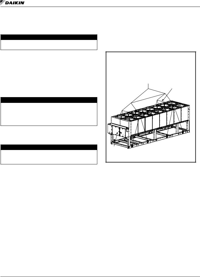
To lift the unit, lifting tabs with 3” (76 mm) diameter holes are provided on the base of the unit. All lifting holes must be used when lifting the unit. Spreader bars and cables should
be arranged to prevent damage to the condenser coils or unit cabinet (see Figure 1).
Location
Locate the unit outdoors and provide proper airflow to the condenser. (See page 5 for required clearances.)Using less clearance than shown in Figure 2 can cause discharge
air recirculation to the condenser and could have a significant detrimental effect on unit performance.
Due to the shape of the condenser coils on Pathfinder® chillers, it is recommended that the unit be oriented so that prevailing winds blow parallel to the unit length, thus minimizing the wind effect on condensing pressure and performance. If low ambient temperature operation is expected, optional louvers should be installed if the unit has no protection against prevailing winds.
Installation and Startup
For pad-mounted units, it is recommended that the unit be raised a few inches with suitable supports such as neoprene waffle vibration pads, located at least under the mounting locations. This will allow water to drain from under the unit and facilitate cleaning under it.
Figure 1: Required Lifting Method
|
|
|
||
|
|
|
|
|
|
|
|
||
|
|
|
||
|
|
|
||
|
|
|
||
|
|
|
|
|
|
|
|
||
|
|
|||
|
|
|
|
|
|
|
|
|
|
|
|
|
|
|
|
|
|
|
|
|
|
|
|
|
|
|
|
|
|
|
|
|
|
|
|
|
|
|
|
|
|
|
|
|
|
|
|
||
|
|
|
|
|
|
|
|
|
|
|
|
|
|
|
|
|
|
||
NOTE: 1.Unit with 8 lifting points illustrated above; the number of condenser sections, fans, and lifting points can vary from this diagram.see lifting/mounting drawings beginning on page 16 to identfy the number of lifting points for a specific unit.
2.All rigging points must be used. See weights at lifting points beginning on page 16 for each specific size unit.
3.Crosswise and lengthwise spreader bars must be used to avoid damage to unit.
Mounting Hole Access
The inside of the base rail is open to allow access for securing mounting bolts, etc.
IOM 1202-2 • PATHFINDER® MODEL AWS CHILLERS |
4 |
www.DaikinApplied.com |

Installation and Startup
Service Access
Compressors, filter-driers, and manual liquid line shutoff valves are accessible on each side or end of the unit. The evaporator heater is located on the barrel.
The control panels are located on the end of the chiller. The left-hand control box contains the unit and circuit
microprocessors as well as transformers, fuses and terminal. The right-hand panel contains a circuit breaker. A minimum of four feet of clearance is required in front of the panels. The side clearance required for airflow provides sufficient service clearance.
On all Pathfinder® units, the condenser fans and motors can be removed from the top of the unit. The complete fan/motor assembly can be removed for service. The fan blade must be removed for access to wiring terminals at the top of the motor.
 DANGER
Disconnect, lockout and tag all power to the unit before servicing condenser fan motors or compressors. Failure to do so can cause bodily injury or death.
Do not block access to the sides or ends of the unit with piping or conduit. These areas must be open for service access.
Do not block access to the control panels with field-mounted disconnect switches.
Clearance Requirements
The clearance requirements shown are a general guideline and cannot account for all scenarios. Such factors as prevailing winds, additional equipment within the space, design outdoor air temperature, and numerous other factors may require more clearance than what is shown.
Figure 2: Guidelines
NOTE: 1 Minimum side clearance between two units is 12 feet (3.7 m). See Case 2 for spacing closer than 12 ft.
2 Minimum clearance on each side is 8 feet (2.4 m) when installed in a pit no deeper than the unit height. Unit must not be installed in a pit or enclosure that is deeper or taller than the height of the unit unless extra clearance is provided per note 4. See Case 5
for performance adjustment factors when installations vary from minimum values.
3 Minimum side clearance to a side wall or building taller than the unit height is 6 feet (1.8 meters), provided no solid wall above 6 feet (1.8 meters) is closer than 12 feet (3.7 meters) to the opposite side of the unit. See Case 1 for performance adjustment factors when installations vary from minimum values.
4 There must be no obstruction of the fan discharge.
Restricted Air Flow
The clearances required for design operation of Pathfinder® air-cooled chillers are described in the previous section. Occasionally, these clearances cannot be maintained due to site restrictions such as units being too close together or a fence or wall restricting airflow, or both. Pathfinder® chillers have several features that may help mitigate the penalties attributable to restricted airflow.
The condenser section is “W” shaped, as shown below. This allows inlet air for these coils to come in from both sides and the bottom. All the coils in one “V” section serve one compressor except for 3 circuit units which use both sides of the “W” shaped condenser coil..
The MicroTech® III control is proactive in response to “offdesign conditions”. In the case of single or compounded influences restricting airflow to the unit, the microprocessor will act to keep the unit running (at reduced capacity), rather than allowing a shut-off on high discharge pressure.
Figure 3: Air Flow
www.DaikinApplied.com |
5 |
IOM 1202-2 • PATHFINDER® MODEL AWS CHILLERS |
Installation and Startup
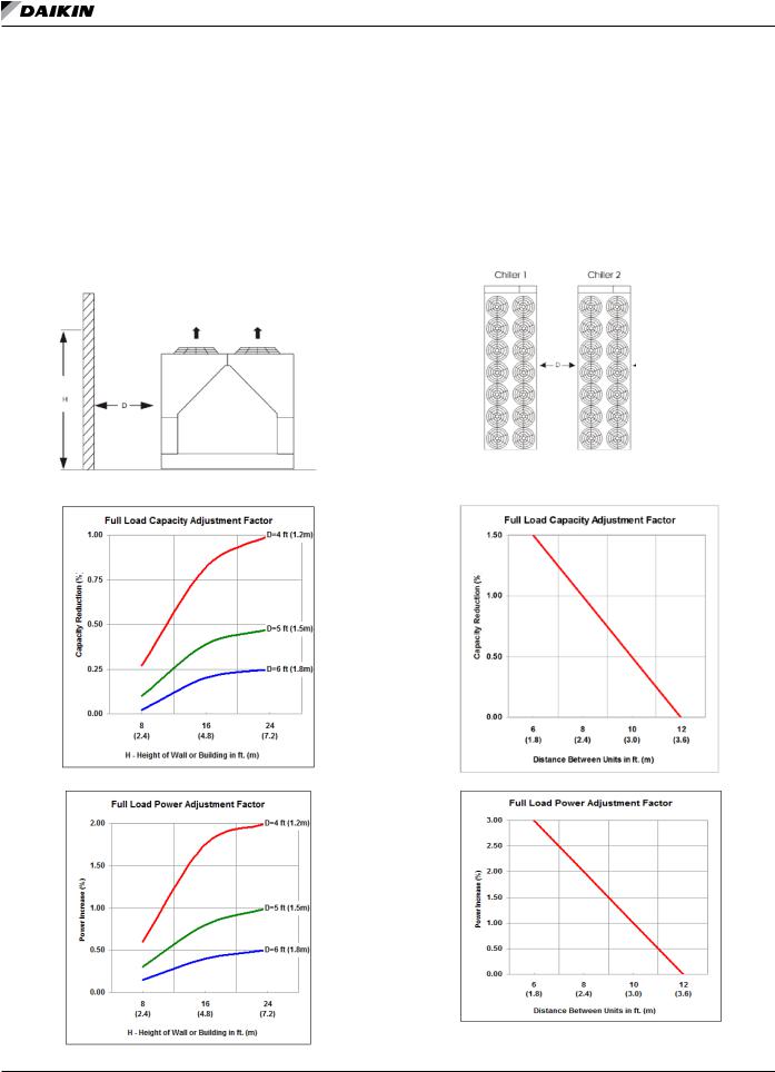
Case 1: Building or Wall on One Side of Unit
The existence of a screening wall or the wall of a building in close proximity to an air-cooled chiller is common in both rooftop and ground level applications. Hot air recirculation on the coils adjoining the wall will increase compressor
discharge pressure, decreasing capacity and increasing power consumption.
When close to a wall, it is desirable to place chillers on the north or east side of them. It is also desirable to have prevailing winds blowing parallel to the unit’s long axis. The worst case is to have wind blowing hot discharge air into the wall.
Figure 4: Case 1 - Unit Adjacent to Wall
Figure 5: Case 1 - Adjustment Factors
Case 2: Two Units Side By Side
Two or more units sited side by side are common. If spaced closer than 12 feet (3.7 meters) it is necessary to adjust the performance of each unit; circuits adjoining each other are affected. If one of the two units also has a wall adjoining it, see Case 1. Add the two adjustment factors together and apply to the unit located between the wall and the other unit.
Mounting units end to end will not necessitate adjusting performance. Do not use pit or solid wall surrounds where the ambient air temperature exceeds 100°F (38°C).
Figure 6: Case 2 - Two Units Side by Side
Figure 7: Case 2 - Adjustment Factors
IOM 1202-2 • PATHFINDER® MODEL AWS CHILLERS |
6 |
www.DaikinApplied.com |
Installation and Startup
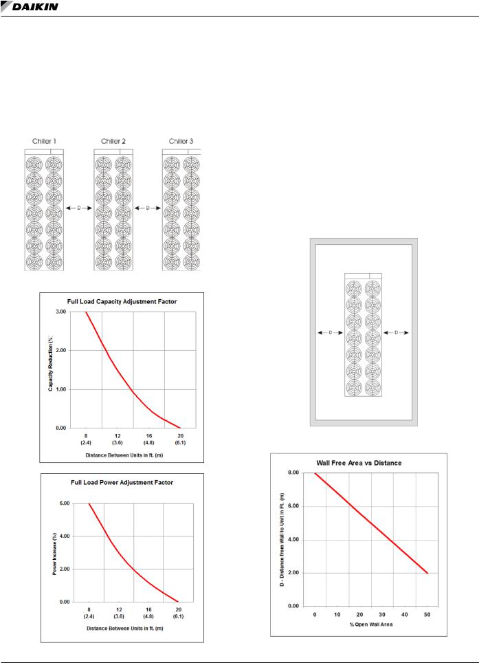
Case 3: Three or More Units Side By Side
When three or more units are side by side, the outside chillers
(1 and 3 in this case) are influenced by the middle unit only on their inside circuits. Their adjustment factors will be the same as Case 2. All inside units (only number 2 in this case) are influenced on both sides and must be adjusted by the factors shown below.
Figure 8: Case 3 - Three or More Units
Figure 9: Case 3 - Adjustment Factors
Case 4: Open Screening Walls
Decorative screening walls are often used to help conceal a unit either on grade or on a rooftop. Design these walls such that the combination of their open area and distance from the unit do not require performance adjustment. It is assumed that the wall height is equal to or less than the unit height when mounted on its base support. This is usually satisfactory for concealment. If the wall height is greater than the unit height, see Case 5, Pit Installation.
The distance from the sides of the unit to the side walls must be sufficient for service, such as opening control panel doors.
If each side wall is a different distance from the unit, the distances can be averaged providing either wall is not less than 8 feet (2.4 meters) from the unit. For example, do not average 4 feet and 20 feet to equal 12 feet (1 meter and 5 meters to equal 3 meters).
Figure 10: Case 4 - Open Screening Walls
Figure 11: Case 4 - Adjustment Factor
www.DaikinApplied.com |
7 |
IOM 1202-2 • PATHFINDER® MODEL AWS CHILLERS |
Installation and Startup
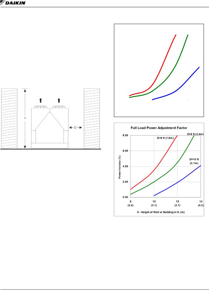
Case 5: Pit/Solid Wall Installation
Pit installations can cause operating problems resulting from recirculation and restriction can both occur. A solid wall surrounding a unit is substantially the same as a pit and the data presented here should be used.
Steel grating is sometimes used to cover a pit to prevent accidental falls or trips into the pit. The grating material and installation design must be strong enough to prevent such accidents, yet provide abundant open area to avoid serious recirculation problems. Have any pit installation reviewed by a Daikin Applied sales representative prior to installation to make sure it has sufficient air-flow characteristics, and approved by the installation design engineer to avoid risk of accident.
Figure 12: Case 5 - Pit Installation
Figure 13: Case 5 - Adjustment Factors
Full Load Capacity Adjustment Factor
|
6..00 |
|
|
|
|
|
|
|
|
|
|
|
|
|
|
|
|
D=6 ft |
|
|
D=8 ft |
|
|
|
|
|
|
|
|
(1..8m) |
|
|
(2..4m) |
|
|
(%) |
5..00 |
|
|
|
|
|
|
|
|
|
|
|
|
|
|
|
|
|
|
|
|
||
|
|
|
|
|
|
|
|
|
|
|
|
Reduction |
4..00 |
|
|
|
|
|
|
|
|
|
|
|
|
|
|
|
|
|
|
|
|
||
3..00 |
|
|
|
|
|
|
|
|
|
|
|
|
|
|
|
|
|
|
|
|
|
||
Capacity |
|
|
|
|
|
|
|
|
|
|
|
|
|
|
|
|
|
|
|
|
D=10 ft |
||
|
|
|
|
|
|
|
|
|
|
||
|
2..00 |
|
|
|
|
|
|
|
|
(3..1m) |
|
|
|
|
|
|
|
|
|
|
|
|
|
|
1..00 |
|
|
|
|
|
|
|
|
|
|
|
|
|
|
|
|
|
|
|
|
|
|
|
0..00 |
|
|
|
|
|
|
|
|
|
|
|
|
|
|
|
|
|
|
|
|
|
|
|
8 |
10 |
12 |
14 |
|||||||
|
(2..4) |
(3..1) |
(3..7) |
(4..3) |
|||||||
H - Height of Wall or Building in ft.. (m)
IOM 1202-2 • PATHFINDER® MODEL AWS CHILLERS |
8 |
www.DaikinApplied.com |
Installation and Startup
Chilled Water Piping
Figure 14: Typical Piping, Shell and Tube Evaporator
|
VENT |
LEAVING FLUID |
|
|
|
3/8” PIPE PLUG |
|
||
|
|
TEMP. SENSOR |
|
|
|
OUTLET |
|
|
VIBRATION |
|
|
|
|
|
|
|
|
|
ELIMINATOR |
INLET |
|
|
|
FLOW |
|
|
|
SWITCH |
|
|
|
VALVED |
|
|
|
|
PRESSURE |
|
|
|
|
GAUGE |
|
GATE |
|
|
VIBRATION |
|
VALVE |
|
|
BALANCING |
||
|
|
ELIMINATOR |
||
|
|
VALVE |
|
|
|
|
|
|
|
DRAIN |
WATER |
GATE |
|
|
|
STRAINER |
|
FLOW |
|
|
VALVE |
|
||
|
|
|
||
PROTECT ALL FIELD PIPING |
|
|
|
|
AGAINST FREEZING |
|
FLOW |
|
|
|
|
|
|
|
 CAUTION
To prevent damage to the evaporator and potential chiller failure, a supply strainer is required in the inlet water piping which connects to this evaporator. This strainer must be installed prior to operation of the chilled liquid pumps.
Field installed water piping to the chiller must include:
•A cleanable strainer installed at the water inlet to the evaporator to remove debris and impurities before they reach the evaporator. Install cleanable strainer within 5 feet (1500 mm) of pipe length from the evaporator inlet connection and downstream of any welded connections (no welded connections between strainer and evaporator).
•AWS-C models require a strainer with perforations no larger than 0.125” (3.2 mm) diameter. See the Inlet Strainer Guidelines on page 10 for more information.
•A water flow switch must be installed in the horizontal piping of the supply (evaporator outlet) water line to avoid evaporator freeze-up under low or no flow conditions. The flow switch may be ordered as a factory-installed option, a field-installed kit, or may be supplied and installed in the field. See page 11 for more information.
•Purge air from the water system before unit start-up to provide adequate flow through the evaporator.
•Adequate piping support, independent from the unit, to eliminate weight and strain on the fittings and connections.
It is recommended that the field installed water piping to the chiller include:
•Thermometers at the inlet and outlet connections of the evaporator.
•Water pressure gauge connection taps and gauges at
the inlet and outlet connections of the evaporator for measuring water pressure drop.
•Shutoff valves are necessary to isolate the unit from the piping during unit servicing.
•Minimum bends and changes in elevation to minimize pressure drop.
•An expansion tank or regulating valve to maintain adequate water pressure
•Vibration eliminators in both the supply and return water lines to reduce transmissions to the building.
•Flush the system water piping thoroughly before making connections to the unit evaporator.
•Piping insulation, including a vapor barrier, helps prevent condensation and reduces heat loss.
•Regular water analysis and chemical water treatment for the evaporator loop is recommended immediately at equipment start-up.
Chilled Water Pump
It is important that the chilled water pumps be wired to, and controlled by, the chiller controller. The chiller controller has the capability to selectively start pump A or B or automatically alternate pump selection and also has standby operation capability. The controller will energize the pump whenever at least one circuit on the chiller is enabled to run, whether there is a call for cooling or not. This helps ensure proper unit startup sequence. The pump will also be turned on when the water temperature goes below the Freeze Setpoint for longer than
a specified time to help prevent evaporator freeze-up. Wiring connection points are shown in Figure 56 on page 60.
www.DaikinApplied.com |
9 |
IOM 1202-2 • PATHFINDER® MODEL AWS CHILLERS |
Installation and Startup
 CAUTION
Adding glycol or draining the system is the recommended method of freeze protection. If the chiller does not have the ability to control the pumps and the water system is not drained in temperatures below freezing, catastrophic evaporator failure may occur. Adding glycol or draining the system is the recommended method of freeze protection. If the chiller does not have the ability to control the pumps and the water system is not drained in temperatures below freezing, catastrophic evaporator failure may occur.
Failure to allow pump control by the chiller controller may cause the following problems:
1.If any device other than the chiller attempts to start the chiller without first starting the pump, the chiller will lock out on the No Flow alarm and require manual reset.
2.If the chiller evaporator water temperature drops below the “Freeze setpoint” the chiller will attempt to start the water pumps to avoid evaporator freeze. If the chiller does not have the ability to start the pumps, the chiller will alarm due to lack of water flow.
3.If the chiller does not have the ability to control the pumps and the water system is not to be drained in temperatures below freezing, the chiller may be subject to catastrophic evaporator failure due to freezing. The freeze rating of the evaporator is based on the immersion heater and pump operation. The immersion heater itself may not be able to properly protect the evaporator from freezing without circulation of water.
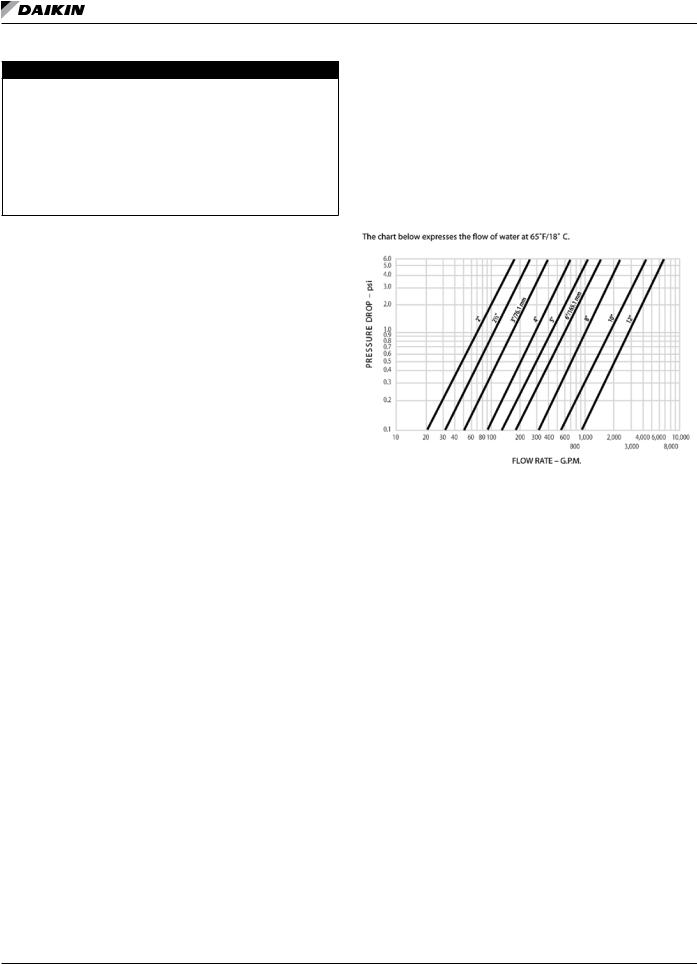
Inlet Strainer Guidelines
An inlet water strainer kit must be installed in the chilled water piping before the evaporator inlet. Two paths are available to meet this requirement:
1.A field-installed kit shipped-loose with the unit is available for all unit sizes and consists of:
•Y-type area strainer with 304 stainless steel perforated basket, Victaulic pipe connections and strainer cap [a strainer with perforations no larger than 0.125” (3.2 mm) diameter for AWS-C models].
•Extension pipe with two Schrader fittings that can be used for a pressure gauge and thermal dispersion flow switch. The pipe provides sufficient clearance from the evaporator for strainer basket removal.
•½-inch blowdown valve
•Two grooved clamps
The strainer is sized per Table 2 and has the pressure drop shown in the Strainer Pressure Drop graph. Connection sizes are given in the Pressure Drop Data section on page 82.
2.A field-supplied strainer that meets specification and installation requirements of this manual.
Table 2: Strainer Sizing Data
Strainer |
Strainer Plus |
Strainer |
|
Pipe Length |
Weight |
||
Size (in.) |
|||
(in.) |
(lbs) |
||
|
|||
|
|
|
|
6 |
30.5 |
72 |
|
8 |
36.0 |
125 |
|
|
|
|
|
10 |
43.0 |
205 |
|
|
|
|
Figure 15: Strainer Pressure Drop
Installing Inlet Strainer (Field-installed Kit)
The extension pipe is located adjacent to the evaporator with the strainer then mounted to it. The strainer must be mounted per manufacturer’s instruction with the arrows in the direction of flow; inlet and outlet are noted along with the arrows.
Use one Victaulic clamp to mount the extension pipe to the evaporator and the second to mount the strainer to the pipe.
The clamps to mount the field piping to the strainer are field supplied. The piping and strainer must be supported to prevent any stress on the evaporator nozzle.
The extension pipe has two Schrader fittings that can be used as desired. The ball valve can be installed in the strainer basket cover as a blow-down valve.
System Water Volume
All chilled water systems need adequate time to recognize a load change, respond to that load change and stabilize, without undesirable short cycling of the compressors or loss of control. In air conditioning systems, the potential for short cycling usually exists when the building load falls below the minimum chiller plant capacity or on close-coupled systems with very small water volumes.
Some of the things the designer should consider when looking at water volume are the minimum cooling load, the minimum chiller plant capacity during the low load period and the desired cycle time for the compressors.
Assuming that there are no sudden load changes and that the chiller plant has reasonable turndown, a rule of thumb of
IOM 1202-2 • PATHFINDER® MODEL AWS CHILLERS |
10 |
www.DaikinApplied.com |

Installation and Startup
“gallons of water volume equal to two to three times the chilled water gpm flow rate” is often used. Refer to AG 31-003 for method of calculating “Minimum Chilled Water Volume”.
A properly designed storage tank may be added if the system components do not provide sufficient water volume.
Variable Speed Pumping
Variable water flow involves reducing the water flow through the evaporator as the load decreases. Daikin chillers are designed for this duty, provided that the rate of change in water flow is slow, and the minimum and maximum flow rates for the evaporator are not exceeded.
The recommended maximum change in water flow is 10 percent of the change per minute. For example, if the maximum (design) flow is 200 gpm and the flow is reduced to a minimum of 140 gpm, the change in flow is 60 gpm, so the maximum change per minute would be 10% of 60, or 6 gpm per minute. It would take ten minutes to change the flow through the entire range.
The water flow through the evaporator must remain between the minimum and maximum values listed, beginning on page 82. Note that units with variable chilled water flow can tolerate lower minimum flows than constant flow systems. If flow drops below the minimum allowable, large reductions in heat transfer can occur. Unit set point “Variable Evap Flow”
must be set to “Yes”, if the chill water flow is variable. If the flow exceeds the maximum rate, excessive pressure drop and tube erosion can occur.
Evaporator Freeze Protection
Pathfinder® chillers are equipped with thermostatically controlled evaporator heaters that help protect against freezeup down to -20°F (-28°C). The immersion heater itself may not be able to properly protect the evaporator from freezing without circulation of water, and it is important that the chilled water pumps are wired to, and controlled by, the chiller’s controller. Additionally, use at least one of the following procedures during periods of sub-freezing temperatures:
1.Add a concentration of a glycol anti-freeze with a freeze point 10°F below the lowest expected temperature. This will result in decreased capacity and increased pressure drop. Do not use automotive grade antifreezes as they contain inhibitors harmful to chilled water systems. Use only glycols specifically designated for use in building cooling systems.
2.Drain the water from outdoor equipment and piping and blow the chiller tubes dry from the chiller. Do not energize the chiller heater when water is drained from the vessel.
NOTE: The heaters come from the factory connected to the control power circuit. The control power can be rewired in the field to a separate 115V supply (do not wire directly to the heater). See the field wiring diagram on page 60. If this is done, it should power the entire control circuit. Mark the disconnect switch clearly to avoid accidental deactivation of the heater during freezing temperatures. Exposed chilled water
piping also requires protection. If the evaporator is drained for winter freeze protection, the heaters must be de-energized to prevent heater burnout.
Table 3: Freeze Protection
|
% Volume Glycol Concentration Required |
|||
Temp. |
|
|
|
|
For Freeze Protection |
For Burst Protection |
|||
°F (°C) |
|
|
|
|
Ethylene |
Propylene |
Ethylene |
Propylene |
|
|
Glycol |
Glycol |
Glycol |
Glycol |
|
|
|
|
|
20 (6.7) |
16 |
18 |
11 |
12 |
|
|
|
|
|
10 (-12.2) |
25 |
29 |
17 |
20 |
|
|
|
|
|
0 (-17.8) |
33 |
36 |
22 |
24 |
|
|
|
|
|
-10 (-23.3) |
39 |
42 |
26 |
28 |
-20 (-28.9) |
44 |
46 |
30 |
30 |
|
|
|
|
|
-30 (-34.4) |
48 |
50 |
30 |
33 |
-40 (-40.0) |
52 |
54 |
30 |
35 |
|
|
|
|
|
-50 (-45.6) |
56 |
57 |
30 |
35 |
|
|
|
|
|
-60 (-51.1) |
60 |
60 |
30 |
35 |
Notes: |
“Freeze protection” maintains the solution in a |
|
pumpable, usable liquid state. “Burst protection” |
|
prevents pipes from rupturing, but solution may be in |
|
a gel state and not pumpable. In most applications, |
|
“burst” protection is sufficient; concentrations over |
|
30% Ethylene Glycol or 35% Propylene Glycol will |
|
result in efficiency and capacity losses with negligible |
|
protection increases and are not recommended. |
|
These values are examples only and cannot be |
|
appropriate to every situation. Generally, for an |
|
extended margin of protection, select a temperature |
|
at least 15°F lower than the expected lowest ambient |
|
temperature. Inhibitor levels should be adjusted for |
|
solutions less than 25% glycol. |
|
Glycol of less than 25% concentration is not |
|
recommended, unless inhibitors are adjusted, |
|
because of the potential for bacterial growth and loss |
|
of efficiency. |
Flow Switch
A flow switch must be included in the chilled water system to prove that there is adequate water flow before the unit can start. It also serves to shut down the unit in the event that water flow is interrupted in order to guard against evaporator freeze-up.
A factory-mounted, solid state, thermal dispersion flow switch is available as an option.
A field-installed and wired version for remote evaporators is also available as a kit (Accessory part number 332688401).
A paddle-type flow switch for field mounting and wiring is also available as a kit (Accessory part number 017503300). It is adaptable to pipe sizes from 1” (25mm) to 8” (203mm).
Installation should be per manufacturer’s instructions included with the switch. There is also a set of normally closed contacts on the switch that can be used for an indicator light or an alarm
www.DaikinApplied.com |
11 |
IOM 1202-2 • PATHFINDER® MODEL AWS CHILLERS |

Installation and Startup
to indicate when a “no flow” condition exists. Flow switches should be calibrated to shut off the unit when operatred below the minimum listed flow rate for the unit listed in the Pressure
Drop section beginning on page 82. The minimum required pipe diameter before and after the switch is 1 1/4” (32 mm).
Figure 16: Flow Switch Diagram
Refrigerant Charge
All packaged units are designed for use with R-134a and are shipped with a full operating charge. The operating charge for each unit is shown in the Physical Data Tables in the current catalog, available at www.DaikinApplied.com.
Glycol Solutions
When using glycol anti-freeze solutions, the chiller’s capacity, glycol solution flow rate, and pressure drop through the evaporator can be calculated using the following:
Note: The procedure below does not specify the type of glycol. Use the derate factors found in Table 4 or Table 5 for corrections when using glycol.
1.Capacity - Cooling capacity is reduced from that with plain water. To find the reduced value, multiply the chiller’s water system tonnage by the capacity correction factor to find the chiller’s capacity when using glycol.
2.Flow - To determine flow (or Delta-T) knowing Delta-T (or flow) and capacity:
GPM = (24) (tons) (flow factor)
Delta T
3.Pressure drop - To determine pressure drop through the evaporator when using glycol, enter the water pressure drop curve at the water flow rate. Multiply the water pressure drop found there by the “PD” factor to obtain corrected glycol pressure drop.
4.Power - To determine glycol system kW, multiply the water system kW by the factor designated “Power”.
Test coolant with a clean, accurate glycol solution hydrometer (similar to that found in service stations) or refractometer
to determine the freezing point. Obtain percent glycol from the freezing point table below. On glycol applications, the
supplier normally recommends that a minimum of 25% solution by weight be used for protection against corrosion or that additional inhibitors should be employed.
 CAUTION
Do not use automotive grade antifreeze. Industrial grade glycols must be used. Automotive antifreeze contains inhibitors that will cause plating on the copper tubes within the chiller evaporator. The type and handling of glycol used must be consistent with local codes.
Performance Adjustment Factors
AWS chillers are designed to operate with leaving anti-freeze solution temperatures per software range limits. Consult the local Daikin Applied sales office for performance outside these temperatures. Leaving chilled fluid temperatures below
40°F (4.4°C) result in evaporating temperatures at or below the freezing point of water and a glycol solution is required. MicroTech® III control inhibits compressor unloading at leaving fluid temperatures below 30°F (-1°C).
Low fluid temperatures or high equipment room humidity may require optional double evaporator insulation. The system designer should determine its necessity. The use of glycol will reduce the performance of the unit depending on its concentration. Take this into consideration during initial system design. On glycol applications, the supplier typically recommends that a minimum of 25% solution by weight be used for protection against corrosion, or additional inhibitors will be required.
Table 4: Ethylene Glycol Correction Factors
% |
Freeze Point |
Capacity |
Power |
Flow |
PD |
||
E..G |
oF |
oC |
|||||
|
|
|
|
||||
10 |
26 |
-3.3 |
0.996 |
0.998 |
1.036 |
1.097 |
|
|
|
|
|
|
|
|
|
20 |
18 |
-7.8 |
0.988 |
0.994 |
1.061 |
1.219 |
|
|
|
|
|
|
|
|
|
30 |
7 |
-13.9 |
0.979 |
0.991 |
1.092 |
1.352 |
|
|
|
|
|
|
|
|
|
40 |
-7 |
-21.7 |
0.969 |
0.986 |
1.132 |
1.532 |
|
|
|
|
|
|
|
|
|
50 |
-28 |
-33.3 |
0.958 |
0.981 |
1.182 |
1.748 |
|
|
|
|
|
|
|
|
|
Table 5: Propylene Glycol Correction Factors
% |
Freeze Point |
Capacity |
Power |
Flow |
PD |
||
P..G |
oF |
oC |
|||||
|
|
|
|
||||
10 |
26 |
-3.3 |
0.991 |
0.996 |
1.016 |
1.092 |
|
|
|
|
|
|
|
|
|
20 |
19 |
-7.2 |
0.981 |
0.991 |
1.032 |
1.195 |
|
|
|
|
|
|
|
|
|
30 |
9 |
-12.8 |
0.966 |
0.985 |
1.056 |
1.345 |
|
|
|
|
|
|
|
|
|
40 |
-5 |
-20.6 |
0.947 |
0.977 |
1.092 |
1.544 |
|
|
|
|
|
|
|
|
|
50 |
-27 |
-32.8 |
0.932 |
0.969 |
1.14 |
1.906 |
|
IOM 1202-2 • PATHFINDER® MODEL AWS CHILLERS |
12 |
www.DaikinApplied.com |
Installation and Startup
Electrical Connections
All wiring must be done in accordance with applicable local and national codes. Pathfinder® units can be ordered with either standard multi-point power or optional single point power connections and with various disconnect and circuit breaker options. Wiring within the unit is sized in accordance with the U.S.A. National Electrical Code. Field-supplied disconnect switches are required if not factory-supplied with the unit.
Table 6: Electric Power Connection Option
Multi-Point |
Single-Point |
|
Power Connection |
Power Connection |
|
Standard: |
Optional: |
|
Disconnect switch per circuit, |
||
one power block, compressor |
||
no compressor isolation |
isolation circuit breakers |
|
circuit breakers |
||
|
||
Optional: |
Optional: |
|
High short circuit current |
one disconnect switch |
|
rated panel with disconnect |
replacing the power block, |
|
switch and no isolation circuit |
compressor isolation circuit |
|
breakers |
breakers |
|
|
Optional: |
|
|
High short circuit current |
|
|
rated panel with disconnect |
|
|
switch and compressor |
|
|
isolation circuit breakers |
NOTE: Disconnect switches are molded case construction with lockable through-the-door handles. They can be used to remove the unit/circuit from the power system.
The individual compressor isolation circuit breakers for each circuit isolate the compressor and do not have through-the-door handles. They are operable only after the panel doors are opened.
The high short circuit rated panel means that a short circuit current up to the ratings shown below will be contained in the panel. There is a short period of time when the circuit breaker will short circuit before opening a circuit that can damage downstream components. In other words, the enclosure is stronger than a standard enclosure. It has a high interrupt rated disconnect switch.
The factory-mounted control power transformer is protected by fuses. Condenser fans are protected and isolated by circuit breakers.
Table 7: Interrupt Ratings (kAmps)
Voltage |
Standard Short Circuit |
High Short Circuit |
|
Rated Panel |
Rated Panel |
||
|
|||
208-230V / 60Hz |
10kA |
100kA |
|
|
|
|
|
380V / 60Hz |
10kA |
65kA |
|
|
|
|
|
460V / 60Hz |
10kA |
65kA |
|
575V / 60Hz |
5kA |
25kA |
|
|
|
|
|
400V / 50Hz |
10kA |
65kA |
|
|
|
|
Disconnecting means are addressed by Article 440 of the U.S.A. National Electrical Code (NEC), which requires “disconnecting means capable of disconnecting air conditioning and refrigerating equipment including motor-compressors,
and controllers from the circuit feeder.” Select and locate the disconnect switch per the NEC guidelines. Maximum
recommended fuse sizes are given in the electrical data tables of this catalog for help in sizing the disconnect.
Terminals are provided in a unit control panel for optional field hookup of the control circuit to a separate fused 115-volt power supply in lieu of the standard factory installed control transformer.
RapidRestore® Options
This option does not require field installation. Exception: Field supplied inputs are required in the case of a backup unit being started after the power interruption rather than restarting the primary unit. A field supplied control (normally a BAS) must turn off the Backup Chiller connection on the primary chiller and turn on the connection on the backup chiller at the time of switching. See the unit Field Wiring Diagram on page 60 for the Backup Unit connection point (terminals #61 and #62).
Economizer Components
The chiller may or may not have economizers depending on design capacity requirements. An economizer is a well-proven device to increase a refrigerant circuit’s capacity and efficiency.
Warm liquid from the condenser is fed into the economizer where it is cooled by flashing off liquid also from the condenser. The flash gas is piped to a compressor interstage point.
Lowering the liquid refrigerant temperature to the evaporator decreases its enthalpy (heat content) and results in a greater amount of heat absorption from the chilled water.
Figure 17: Economizer Components
www.DaikinApplied.com |
13 |
IOM 1202-2 • PATHFINDER® MODEL AWS CHILLERS |

CHILLERS AWS MODEL ®PATHFINDER • 2-1202 IOM
14
com.DaikinApplied.www
|
|
|
|
|
|
|
RANSDUCERSUCTION |
|
|
|
AWS PACKAGE CHILLER |
|
|
|
|
T |
|
|
|
WITH ECONOMIZER |
|
|
|
|
|
|
|
|
331994701 REV. 0D |
|
|
|
|
|
|
|
|
SCHRADER |
|
|
|
|
|
|
CONDENSER |
AIR |
VALVE |
|
|
|
|
|
|
FLOW |
(HEADER) |
|
|
CHECK |
|
BUTTERFLY |
||
ASSEMBLY |
|
|
|
|
OIL PRESS. |
|
VALVE |
|
|
|
|
|
|
VALVE |
|
||
|
|
DISCHARGE |
DISCHARGE |
SHUT-OFF |
TRANSDUCER |
(OPTIONAL) |
||
|
|
TUBING |
TRANSDUCER |
VALVE |
|
WITH SCHRADER |
|
|
|
|
|
|
|
|
VALVE |
|
|
BALL |
CHARGING |
OUTSIDE AIR |
RELIEF |
|
|
VALVE |
|
||||
VALVE |
VALVE |
SCHRADER |
TEMPERATURE |
|
|
|
|
(WAA) |
|
|
|
|
|
VALVE |
DISCHARGE |
|
|
|
|
|
|
||
|
|
|
|
TEMP. SENSOR |
F3/F4 |
|
|
|
|
|
COMPRESSOR |
LIQUID |
|
AIR |
|
|
|
BALL |
SCHRADER |
LIQUID |
|
CHECK |
|
|
FLOW |
|
|
|
VALVE |
VALVE |
INJECTION STRAINER |
SOLENOID |
VALVE |
|
|
TUBING |
|
|
|
|
|
|
|||||
|
|
|
|
|
|
|
|
TUBING |
VALVE |
|
|
|
|
|
ECONOMIZER FLASH GAS TO COMPRESSOR INTERSTAGE |
|
|
|
|||||
SCHRADER |
SCHRADER |
|
|
|
|
|
|
|
|
SUCTION |
|
|
VALVE |
|
|
|
|
|
|
|
|
||
VALVE |
|
|
|
|
|
|
|
|
|
||
|
|
|
|
|
|
|
|
|
|
TUBING |
|
|
|
|
|
|
|
|
|
|
|
|
|
FILTER |
SCHRADER SIGHT |
SOLENOID |
|
|
|
|
|
Note: Provide 20-mesh strainer |
|||
VALVE |
|
|
|
|
|
||||||
DRYER |
CHARGING |
GLASS |
VALVE |
|
|
|
|
|
at evaporator inlet |
||
|
|
|
|
|
|
|
|
|
|||
|
VALVE |
|
|
|
|
|
|
|
|
|
|
|
|
|
TGE |
|
|
|
WATER OUT |
|
WATER IN |
|
|
|
|
|
|
|
|
|
|
|
|
||
|
|
|
EXPANSION |
|
|
|
|
(WOE) |
(WIE) |
|
|
|
|
|
VALVE |
|
|
|
|
|
|
||
|
|
|
|
|
|
|
TEMP. SENSOR |
TEMP. SENSOR |
|
||
|
|
|
|
|
|
|
|
|
|||
|
|
ECONOMIZER |
SOLENOID |
SCHRADER |
EXPANSION CHARGING |
DX EVAPORATOR |
RELIEF |
SUCTION |
|||
|
|
VALVE |
|||||||||
|
|
|
(OPTIONAL) |
VALVE |
VALVE |
VALVE |
|
|
|
VALVE |
TEMP. SENSOR |
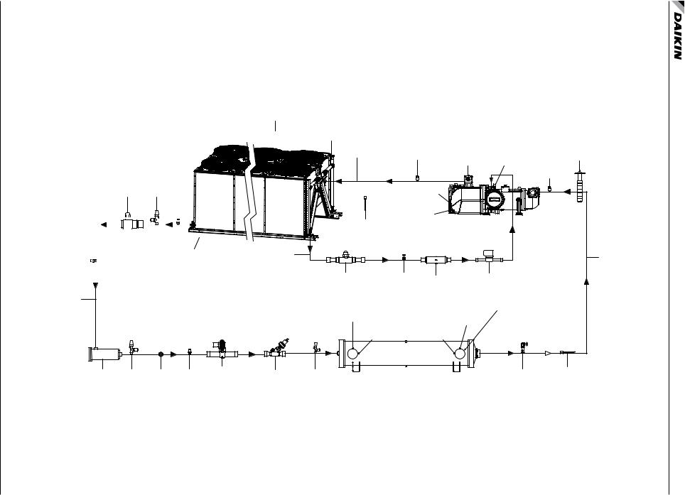
Shown Circuit One Circuit, Economizer with Schematic Piping 18: Figure
tartupS and nstallationI
com.DaikinApplied.www
15
CHILLERS AWS MODEL ®PATHFINDER • 2-1202 IOM
CONDENSER
ASSEMBLY
BALL CHARGING
VALVE VALVE
SCHRADER
VALVE
|
|
|
|
|
|
|
|
|
|
|
|
|
|
|
|
|
|
|
|
|
|
|
|
|
|
|
|
|
|
|
|
|
|
|
|
|
|
|
|
|
|
|
|
|
|
|
|
|
|
|
|
|
|
|
|
|
|
SCHRADER |
|
|
|
|
|
|
|
|
|
|
|
|
|
|
|
|
|
|
|
|
|
|
|
AIR |
||||
|
|
|
|
|
|
|
|
|
|
|
|
|
|
|
|
|
|
|
|
|
|
|
FLOW |
|||||
|
|
|
|
|
|
|
|
|
|
|
|
|
|
|
|
|
|
|
|
|
|
|
|
|
|
|
||
VALVE |
|
|
|
|
|
|
|
|
|
|
|
|
|
|
|
|
|
|
|
|
|
|
|
|
|
|
|
|
|
|
|
|
|
|
|
|
|
|
|
|
|
|
|
|
|
|
|
|
|
|
|
|
|
|
|
|
|
LIQUID
TUBING
FILTER CHARGING SIGHT SCHRADER SOLENOID DRYER VALVE GLASS VALVE VALVE
(OPTIONAL)
AWS PACKAGE CHILLER 331994701 REV. 0D
|
SCHRADER |
|
|
AIR |
VALVE |
|
|
(HEADER) |
|
|
|
FLOW |
|
|
|
|
|
|
|
|
DISCHARGE |
DISCHARGE |
|
|
TUBING |
TRANSDUCER |
SHUT-OFF |
|
|
|
|
|
|
|
VALVE |
|
RANSDUCERSUCTION |
|
OIL PRESS. |
T |
|
BUTTERFLY |
||
TRANSDUCER |
|
VALVE |
WITH SCHRADER |
(OPTIONAL) |
|
VALVE |
|
|
|
RELIEF |
|
|
VALVE |
|
|
DISCHARGE |
F3/F4 |
OUTSIDE AIR |
TEMP. SENSOR |
|
TEMPERATURE |
|
COMPRESSOR |
(WAA) |
|
|
LIQUID |
|
|
SUCTION |
INJECTION |
|
|
|
TUBING |
|
|
TUBING |
BALL |
SCHRADER |
STRAINER |
SOLENOID |
VALVE |
VALVE |
|
VALVE |
|
|
|
|
Note: Provide 20-mesh strainer |
|
|
|
WATER OUT |
|
at evaporator inlet |
|
|
|
|
WATER IN |
|
|
|
|
|
|
|
|
|
|
(WOE) |
|
(WIE) |
|
|
|
TEMP. SENSOR |
TEMP. SENSOR |
|
|
EXPANSION |
CHARGING |
DX EVAPORATOR |
RELIEF |
SUCTION |
|
VALVE |
VALVE |
|
|
VALVE |
TEMP. SENSOR |
Shown Circuit One Circuit, Economizer without Schematic Piping 19: Figure
tartupS and nstallationI
Lifting and Mounting Information
Lifting and Mounting Information
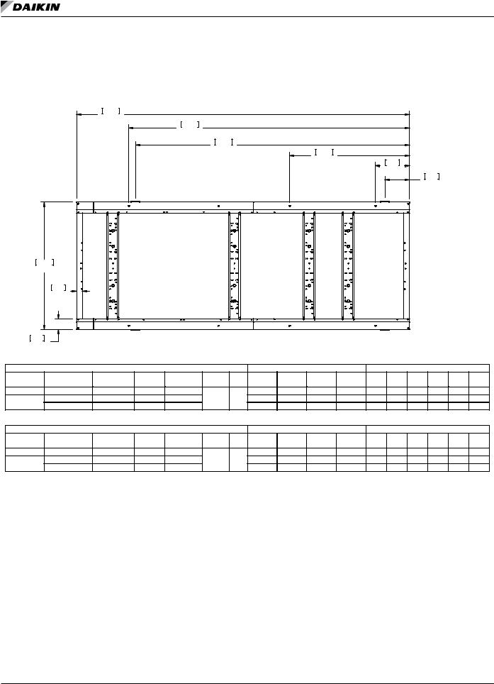
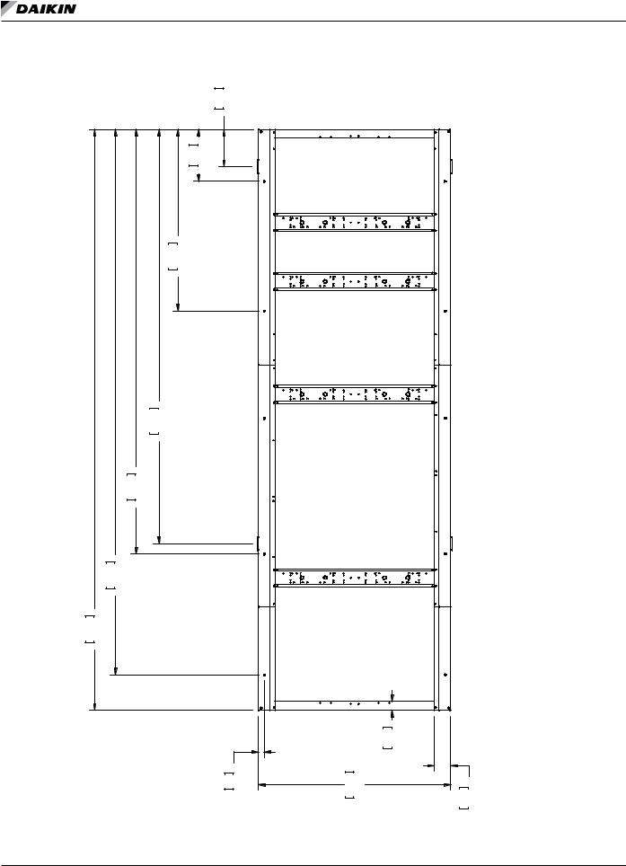
Figure 20: 10 Fan Non-VFD Models
5820 |
|
|
|
|
229.1 |
|
|
|
|
|
|
4910 |
|
|
|
|
193.3 |
|
|
|
|
4791 |
|
|
|
|
188.6 |
2100 |
|
|
|
|
|
|
|
|
|
82.7 |
600 |
|
|
|
|
|
|
|
|
|
23.6 |
|
|
|
|
431 |
|
|
|
|
17.0 |
M5 |
L3 |
M3 |
M1 |
L1 |
|
|
|
|
|
|
|
|
|
|
|
|
|
|
BOX |
|
|
|
|
|
2225 |
|
|
|
|
|
|
|
|
|
|
|
|
CONTROL |
|
|
|
|
||
|
|
|
|
|
|
|
|
|
|
|
|
|
|
|
|
|
|||
87.6 |
|
|
|
|
|
|
|
|
|
|
|
|
|
|
|
|
|
||
|
100 |
|
|
|
|
|
|
|
|
|
|
|
|
|
|
|
|
|
|
|
3.9 |
|
|
|
|
|
|
|
|
|
|
|
|
|
|
|
|
|
|
190 |
|
|
M6 |
L4 |
|
|
|
|
M4 |
|
|
M2 |
L2 |
AWS 10 FAN DIM. DWG |
|||||
7.5 |
|
|
|
|
|
|
|
|
|
|
|
|
|
||||||
|
|
|
|
|
|
|
|
|
|
|
|
|
330973501 |
0A |
|
||||
|
|
|
|
|
|
|
|
|
|
|
|
|
|
|
|||||
|
AWS DIMENSIONAL DATA - WEIGHTS IN LBS. |
|
|
LIFTING WEIGHT FOR EACH POINT LB |
MOUNTING LOADS FOR EACH POINT LB |
||||||||||||||
UNIT SIZE |
VOLTAGE |
HZ. |
STARTER |
SHIPPING OPERATING COPPER # OF |
L1 |
L2 |
L3 |
L4 |
M1 |
M2 |
M3 |
M4 |
M5 |
M6 |
|||||
WEIGHT |
WEIGHT |
FIN ADD FANS |
|||||||||||||||||
|
|
|
|
|
|
|
|
|
|
|
|
|
|
|
|||||
AWS164CDS |
400V - 50HZ |
WYE DELTA |
12535 |
12778 |
|
|
3843 |
3825 |
2439 |
2428 |
2670 |
2658 |
2255 |
2245 |
1478 |
1472 |
|||
AWS190CDS |
380-575V - 60HZ SOLID STATE |
12829 |
13072 |
1786 |
10 |
4015 |
3997 |
2414 |
2403 |
2805 |
2792 |
2324 |
2313 |
1422 |
1415 |
||||
|
208-575V - 60HZ |
WYE DELTA |
12535 |
12778 |
|
|
3843 |
3825 |
2439 |
2428 |
2670 |
2658 |
2255 |
2245 |
1478 |
1472 |
|||
|
AWS DIMENSIONAL DATA - WEIGHTS IN KG. |
|
|
LIFTING WEIGHT FOR EACH POINT KG |
MOUNTING LOADS FOR EACH POINT KG |
||||||||||||||
UNIT SIZE |
VOLTAGE |
HZ. |
STARTER |
SHIPPING OPERATING COPPER # OF |
L1 |
L2 |
L3 |
L4 |
M1 |
M2 |
M3 |
M4 |
M5 |
M6 |
|||||
WEIGHT |
WEIGHT |
FIN ADD FANS |
|||||||||||||||||
|
|
|
|
|
|
|
|
|
|
|
|
|
|
|
|||||
AWS164CDS |
400V - 50HZ |
WYE DELTA |
5686 |
5796 |
|
|
1743 |
1735 |
1106 |
1101 |
1211 |
1206 |
1023 |
1018 |
670 |
668 |
|||
AWS190CDS |
380-575V - 60HZ SOLID STATE |
5819 |
5929 |
810 |
10 |
1821 |
1813 |
1095 |
1090 |
1272 |
1266 |
1054 |
1049 |
645 |
642 |
||||
|
208-575V - 60HZ |
WYE DELTA |
5686 |
5796 |
|
|
1743 |
1735 |
1106 |
1101 |
1211 |
1206 |
1023 |
1018 |
670 |
668 |
|||
IOM 1202-2 • PATHFINDER® MODEL AWS CHILLERS |
16 |
www.DaikinApplied.com |

Lifting and Mounting Information
Figure 21: 12 Fan Non-VFD Models
|
AWS 12 FAN DIM. DWG |
330973502 0A |
|
|
5820 |
|
|
|
|
229.1 |
4910 |
|
|
|
|
|
|
|
|
|
193.3 |
|
|
|
|
4791 |
|
|
|
|
188.6 |
|
2100 |
|
|
|
|
|
|
|
|
|
82.7 |
600 |
|
|
|
|
|
|
|
|
|
23.6 |
|
|
|
|
431 |
|
|
|
|
17.0 |
M5 |
L3 |
M3 |
M1 |
L1 |
2225
87.6
190
7.5
|
|
|
|
|
|
|
|
|
|
|
|
|
|
|
|
BOX |
||
100 |
|
|
|
|
|
|
|
|
|
|
|
|
|
|
|
CONTROL |
||
|
|
|
|
|
|
|
|
|
|
|
|
|
|
|
|
|
||
3.9 |
|
|
|
|
|
|
|
|
|
|
|
|
|
|
|
|
|
|
|
M6 |
L4 |
|
|
|
|
|
M4 |
|
|
|
M2 |
L2 |
|
|
|||
|
AWS DIMENSIONAL DATA - WEIGHTS IN LBS. |
|
|
LIFTING WEIGHT FOR EACH POINT LB |
MOUNTING LOADS FOR EACH POINT LB |
|||||||||||||
UNIT SIZE |
VOLTAGE |
HZ. |
STARTER |
SHIPPING OPERATING COPPER # OF |
L1 |
L2 |
L3 |
L4 |
M1 |
M2 |
M3 |
M4 |
M5 |
M6 |
||||
WEIGHT |
WEIGHT |
FIN ADD FANS |
||||||||||||||||
|
|
|
|
|
|
|
|
|
|
|
|
|
|
|||||
AWS174CDH |
400V - 50HZ |
WYE DELTA |
13174 |
13357 |
|
|
3823 |
3805 |
2779 |
2767 |
2598 |
2586 |
2314 |
2303 |
1782 |
1773 |
||
AWS184CDS |
400V - 50HZ |
WYE DELTA |
13290 |
13503 |
|
|
4154 |
3968 |
2643 |
2525 |
2876 |
2747 |
2431 |
2323 |
1599 |
1527 |
||
AWS204CDS |
400V - 50HZ |
WYE DELTA |
13789 |
14032 |
|
|
4283 |
4264 |
2627 |
2615 |
2982 |
2969 |
2488 |
2477 |
1562 |
1555 |
||
AWS210CDH |
380-575V - 60HZ SOLID STATE |
13470 |
13653 |
|
|
3999 |
3981 |
2751 |
2739 |
2737 |
2724 |
2383 |
2373 |
1722 |
1714 |
|||
208-575V - 60HZ |
WYE DELTA |
13174 |
13357 |
|
|
3823 |
3805 |
2779 |
2767 |
2598 |
2586 |
2314 |
2303 |
1782 |
1773 |
|||
|
|
|
||||||||||||||||
|
380-575V - 60HZ SOLID STATE |
13575 |
13788 |
1786 |
12 |
4320 |
4126 |
2623 |
2506 |
3005 |
2871 |
2498 |
2387 |
1548 |
1479 |
|||
AWS210CDS |
208-230V - 60HZ |
WYE DELTA |
|
|
||||||||||||||
|
|
|
|
|
|
|
|
|
|
|
|
|
|
|||||
|
380-575V - 60HZ |
WYE DELTA |
13290 |
13503 |
|
|
4154 |
3968 |
2643 |
2525 |
2876 |
2747 |
2431 |
2323 |
1599 |
1527 |
||
|
380-575V - 60HZ SOLID STATE |
14092 |
14335 |
|
|
4459 |
4439 |
2603 |
2591 |
3121 |
3106 |
2558 |
2547 |
1505 |
1498 |
|||
AWS225CDS |
208-230V - 60HZ |
WYE DELTA |
|
|
||||||||||||||
|
|
|
|
|
|
|
|
|
|
|
|
|
|
|||||
|
380-575V - 60HZ |
WYE DELTA |
13789 |
14032 |
|
|
4283 |
4264 |
2627 |
2615 |
2982 |
2969 |
2488 |
2477 |
1562 |
1555 |
||
|
AWS DIMENSIONAL DATA - WEIGHTS IN KG. |
|
|
LIFTING WEIGHT FOR EACH POINT KG |
MOUNTING LOADS FOR EACH POINT KG |
|||||||||||||
UNIT SIZE |
VOLTAGE |
HZ. |
STARTER |
SHIPPING OPERATING COPPER # OF |
L1 |
L2 |
L3 |
L4 |
M1 |
M2 |
M3 |
M4 |
M5 |
M6 |
||||
WEIGHT |
WEIGHT |
FIN ADD FANS |
||||||||||||||||
|
|
|
|
|
|
|
|
|
|
|
|
|
|
|||||
AWS174CDH |
400V - 50HZ |
WYE DELTA |
5976 |
6059 |
|
|
1734 |
1726 |
1261 |
1255 |
1179 |
1173 |
1050 |
1045 |
808 |
804 |
||
AWS184CDS |
400V - 50HZ |
WYE DELTA |
6028 |
6125 |
|
|
1884 |
1800 |
1199 |
1145 |
1304 |
1246 |
1103 |
1054 |
725 |
693 |
||
AWS204CDS |
400V - 50HZ |
WYE DELTA |
6255 |
6365 |
|
|
1943 |
1934 |
1192 |
1186 |
1353 |
1347 |
1129 |
1123 |
708 |
705 |
||
AWS210CDH |
380-575V - 60HZ SOLID STATE |
6110 |
6193 |
|
|
1814 |
1806 |
1248 |
1242 |
1241 |
1236 |
1081 |
1076 |
781 |
778 |
|||
208-575V - 60HZ |
WYE DELTA |
5976 |
6059 |
|
|
1734 |
1726 |
1261 |
1255 |
1179 |
1173 |
1050 |
1045 |
808 |
804 |
|||
|
|
|
||||||||||||||||
|
380-575V - 60HZ SOLID STATE |
6158 |
6254 |
810 |
12 |
1960 |
1872 |
1190 |
1137 |
1363 |
1302 |
1133 |
1083 |
702 |
671 |
|||
AWS210CDS |
208-230V - 60HZ |
WYE DELTA |
||||||||||||||||
|
|
|
|
|
|
|
|
|
|
|
|
|
|
|||||
|
380-575V - 60HZ |
WYE DELTA |
6028 |
6125 |
|
|
1884 |
1800 |
1199 |
1145 |
1304 |
1246 |
1103 |
1054 |
725 |
693 |
||
|
380-575V - 60HZ SOLID STATE |
6392 |
6502 |
|
|
2023 |
2014 |
1181 |
1175 |
1416 |
1409 |
1160 |
1155 |
683 |
680 |
|||
AWS225CDS |
208-230V - 60HZ |
WYE DELTA |
|
|
||||||||||||||
|
|
|
|
|
|
|
|
|
|
|
|
|
|
|||||
|
380-575V - 60HZ |
WYE DELTA |
6255 |
6365 |
|
|
1943 |
1934 |
1192 |
1186 |
1353 |
1347 |
1129 |
1123 |
708 |
705 |
||
www.DaikinApplied.com |
17 |
IOM 1202-2 • PATHFINDER® MODEL AWS CHILLERS |
Lifting and Mounting Information
Figure 22: 14 Fan Non-VFD Models
|
|
|
|
|
|
431 |
17.0 |
|
|
CONTROLBOX |
|
|
||
|
|
|
|
|
|
|
|
|
|
|
|
|||
|
|
|
|
|
600 |
23.6 |
|
|
L1 |
|
|
L2 |
|
|
|
|
|
|
|
|
|
|
|
M1 |
|
|
M2 |
|
|
|
|
|
|
2100 |
82.7 |
|
|
|
|
|
|
|
|
|
|
|
|
|
|
|
|
|
|
M3 |
|
|
M4 |
|
|
|
|
|
|
|
|
|
|
|
|
|
|
|
|
|
|
|
|
4791 |
188.6 |
|
|
|
|
|
|
|
|
AWS 14 FAN DIM. DWG |
330973503 0A |
|
|
4910 |
193.3 |
|
|
|
|
|
|
|
|
|
|
|
|
|
|
|
|
|
|
|
|
L3 |
|
|
L4 |
|
|
|
6310 |
248.4 |
|
|
|
|
|
|
M5 |
|
|
M6 |
|
|
6720 |
264.6 |
|
|
|
|
|
|
|
|
|
|
|
|
|
|
|
|
|
|
|
|
|
|
M7 |
|
|
M8 |
|
|
|
|
|
|
|
|
|
|
|
|
|
100 |
3.9 |
|
|
|
|
|
|
|
|
|
66 |
2.6 |
|
2225 |
87.6 |
190 |
7.5 |
|
IOM 1202-2 • PATHFINDER® MODEL AWS CHILLERS |
18 |
|
|
|
www.DaikinApplied.com |
|||||||||
com.DaikinApplied.www
19
CHILLERS AWS MODEL ®PATHFINDER • 2-1202 IOM
|
AWS 14 FAN DIM. DWG |
330973503 |
0A |
|
|
|
|
|
|
|
|
|
|
|
|
|
|
|||||
|
|
|
|
|
|
|
|
|
|
|
|
|||||||||||
|
AWS DIMENSIONAL DATA - WEIGHTS IN LBS. |
|
|
|
LIFTING WEIGHT FOR EACH POINT LB |
|
MOUNTING LOADS FOR EACH POINT LB |
|
||||||||||||||
|
|
|
|
|
|
|
|
|
|
|
|
|
|
|
|
|
|
|
|
|
||
UNIT SIZE |
VOLTAGE |
HZ. |
STARTER |
SHIPPING |
OPERATING |
COPPER |
# OF |
L1 |
L2 |
L3 |
L4 |
M1 |
M2 |
M3 |
M4 |
M5 |
M6 |
M7 |
|
M8 |
||
WEIGHT |
WEIGHT |
|
FIN ADD |
FANS |
|
|||||||||||||||||
|
|
|
|
|
|
|
|
|
|
|
|
|
|
|
|
|
|
|||||
AWS204CDH |
400V 50HZ |
WYE DELTA |
|
14740 |
14863 |
|
|
|
3983 |
3770 |
3589 |
3398 |
2976 |
2818 |
2420 |
2291 |
1379 |
1305 |
860 |
|
814 |
|
|
|
|
|
|
|
|
|
|
|
|
|
|
|
|
|
|
|
|
|
|
|
|
AWS224-234CDS |
400V 50HZ |
WYE DELTA |
|
14714 |
14887 |
|
|
|
4141 |
4122 |
3233 |
3218 |
3073 |
3059 |
2444 |
2433 |
1266 |
1260 |
679 |
|
676 |
|
|
|
|
|
|
|
|
|
|
|
|
|
|
|
|
|
|
|
|
|
|
|
|
AWS224CDH |
400V 50HZ |
WYE DELTA |
|
15420 |
15523 |
|
|
|
4092 |
4092 |
3619 |
3619 |
3048 |
3048 |
2471 |
2471 |
1390 |
1390 |
852 |
|
852 |
|
|
|
|
|
|
|
|
|
|
|
|
|
|
|
|
|
|
|
|
|
|
|
|
|
380-575V 60HZ |
SOLID STATE |
|
15042 |
15165 |
|
|
|
4168 |
3928 |
3576 |
3370 |
3103 |
2924 |
2503 |
2359 |
1380 |
1301 |
821 |
|
774 |
|
|
|
|
|
|
|
|
|
|
||||||||||||||
AWS230CDH |
208-230V 60HZ |
WYE DELTA |
|
|
|
|
|
|||||||||||||||
|
|
|
|
|
|
|
|
|
|
|
|
|
|
|
|
|
|
|
||||
|
|
|
|
|
|
|
|
|
|
|
|
|
|
|
|
|
|
|
|
|
|
|
|
380-575V 60HZ |
WYE DELTA |
|
14740 |
14863 |
|
|
|
3983 |
3770 |
3589 |
3398 |
2976 |
2818 |
2420 |
2291 |
1379 |
1305 |
860 |
|
814 |
|
|
|
|
|
|
|
|
2084 |
14 |
|
|
|
|
|
|
|
|
|
|
|
|
|
|
|
380-575V 60HZ |
SOLID STATE |
|
15015 |
15188 |
|
4313 |
4294 |
3212 |
3197 |
3190 |
3175 |
2519 |
2508 |
1264 |
1258 |
638 |
|
635 |
|||
|
|
|
|
|
|
|
|
|
||||||||||||||
AWS250-260CDS |
208-230V 60HZ |
WYE DELTA |
|
|
|
|
|
|||||||||||||||
|
|
|
|
|
|
|
|
|
|
|
|
|
|
|
|
|
|
|
||||
|
|
|
|
|
|
|
|
|
|
|
|
|
|
|
|
|
|
|
|
|
|
|
|
380-575V 60HZ |
WYE DELTA |
|
14714 |
14887 |
|
|
|
4141 |
4122 |
3233 |
3218 |
3073 |
3059 |
2444 |
2433 |
1266 |
1260 |
679 |
|
676 |
|
|
|
|
|
|
|
|
|
|
|
|
|
|
|
|
|
|
|
|
|
|
|
|
|
380-575V 60HZ |
SOLID STATE |
|
15722 |
15825 |
|
|
|
4277 |
4258 |
3601 |
3585 |
3175 |
3160 |
2554 |
2542 |
1391 |
1385 |
811 |
|
808 |
|
|
|
|
|
|
|
|
|
|
||||||||||||||
AWS250CDH |
208-230V 60HZ |
WYE DELTA |
|
|
|
|
|
|||||||||||||||
|
|
|
|
|
|
|
|
|
|
|
|
|
|
|
|
|
|
|
||||
|
|
|
|
|
|
|
|
|
|
|
|
|
|
|
|
|
|
|
|
|
|
|
|
380-575V 60HZ |
WYE DELTA |
|
15420 |
15523 |
|
|
|
4092 |
4092 |
3619 |
3619 |
3048 |
3048 |
2471 |
2471 |
1390 |
1390 |
852 |
|
852 |
|
|
|
|
|
|
|
|
|
|
|
|
|
|
|
|
|
|
|
|
|
|
||
|
|
|
|
|
|
|
|
|
|
|||||||||||||
|
AWS DIMENSIONAL DATA - WEIGHTS IN KG. |
|
|
|
LIFTING WEIGHT FOR EACH POINT KG |
|
MOUNTING LOADS FOR EACH POINT LB |
|
||||||||||||||
|
|
|
|
|
|
|
|
|
|
|
|
|
|
|
|
|
|
|
||||
UNIT SIZE |
VOLTAGE |
HZ. |
STARTER |
SHIPPING |
OPERATING |
COPPER |
# OF |
L1 |
L2 |
L3 |
L4 |
M1 |
M2 |
M3 |
M4 |
M5 |
M6 |
M7 |
|
M8 |
||
WEIGHT |
WEIGHT |
|
FIN ADD |
FANS |
|
|||||||||||||||||
|
|
|
|
|
|
|
|
|
|
|
|
|
|
|
|
|
|
|||||
|
|
|
|
|
|
|
|
|
|
|
|
|
|
|
|
|
|
|
|
|
|
|
AWS204CDH |
400V 50HZ |
WYE DELTA |
|
6686 |
6742 |
|
|
|
1807 |
1710 |
1628 |
1541 |
1350 |
1278 |
1098 |
1039 |
625 |
592 |
390 |
|
369 |
|
AWS224-234CDS |
400V 50HZ |
WYE DELTA |
|
6674 |
6753 |
|
|
|
1878 |
1870 |
1467 |
1460 |
1394 |
1387 |
1108 |
1103 |
574 |
571 |
308 |
|
306 |
|
|
|
|
|
|
|
|
|
|
|
|
|
|
|
|
|
|
|
|
|
|
|
|
AWS224CDH |
400V 50HZ |
WYE DELTA |
|
6995 |
7041 |
|
|
|
1856 |
1856 |
1641 |
1641 |
1383 |
1383 |
1121 |
1121 |
631 |
631 |
386 |
|
386 |
|
|
|
|
|
|
|
|
|
|
|
|
|
|
|
|
|
|
|
|
|
|
|
|
|
380-575V 60HZ |
SOLID STATE |
|
6823 |
6879 |
|
|
|
1891 |
1782 |
1622 |
1529 |
1407 |
1326 |
1135 |
1070 |
626 |
590 |
372 |
|
351 |
|
|
|
|
|
|
|
|
|
|
||||||||||||||
AWS230CDH |
208-230V 60HZ |
WYE DELTA |
|
|
|
|
|
|||||||||||||||
|
|
|
|
|
|
|
|
|
|
|
|
|
|
|
|
|
|
|
||||
|
|
|
|
|
|
|
|
|
|
|
|
|
|
|
|
|
|
|
|
|
|
|
|
380-575V 60HZ |
WYE DELTA |
|
6686 |
6742 |
|
|
|
1807 |
1710 |
1628 |
1541 |
1350 |
1278 |
1098 |
1039 |
625 |
592 |
390 |
|
369 |
|
|
|
|
|
|
|
|
945 |
14 |
|
|
|
|
|
|
|
|
|
|
|
|
|
|
|
380-575V 60HZ |
SOLID STATE |
|
6811 |
6889 |
|
1956 |
1948 |
1457 |
1450 |
1447 |
1440 |
1143 |
1138 |
573 |
571 |
290 |
|
288 |
|||
|
|
|
|
|
|
|
|
|
||||||||||||||
AWS250-260CDS |
208-230V 60HZ |
WYE DELTA |
|
|
|
|
|
|||||||||||||||
|
|
|
|
|
|
|
|
|
|
|
|
|
|
|
|
|
|
|
||||
|
|
|
|
|
|
|
|
|
|
|
|
|
|
|
|
|
|
|
|
|
|
|
|
380-575V 60HZ |
WYE DELTA |
|
6674 |
6753 |
|
|
|
1878 |
1870 |
1467 |
1460 |
1394 |
1387 |
1108 |
1103 |
574 |
571 |
308 |
|
306 |
|
|
|
|
|
|
|
|
|
|
|
|
|
|
|
|
|
|
|
|
|
|
|
|
|
380-575V 60HZ |
SOLID STATE |
|
7131 |
7178 |
|
|
|
1940 |
1931 |
1634 |
1626 |
1440 |
1433 |
1158 |
1153 |
631 |
628 |
368 |
|
366 |
|
|
|
|
|
|
|
|
|
|
||||||||||||||
AWS250CDH |
208-230V 60HZ |
WYE DELTA |
|
|
|
|
|
|||||||||||||||
|
|
|
|
|
|
|
|
|
|
|
|
|
|
|
|
|
|
|
||||
|
|
|
|
|
|
|
|
|
|
|
|
|
|
|
|
|
|
|
|
|
|
|
|
380-575V 60HZ |
WYE DELTA |
|
6995 |
7041 |
|
|
|
1856 |
1856 |
1641 |
1641 |
1383 |
1383 |
1121 |
1121 |
631 |
631 |
386 |
|
386 |
|
|
|
|
|
|
|
|
|
|
|
|
|
|
|
|
|
|
|
|
|
|
|
|
(continued) Models VFD-Non Fan 14 23: Figure
nformationI ountingM and iftingL

|
|
|
|
|
|
|
|
|
|
|
|
|
Lifting and Mounting Information |
|
Figure 24: 16 Fan Non-VFD Models |
|
|
|
|
|
|
|
|
|
|||||
|
|
|
|
|
|
|
431 |
17.0 |
|
|
|
|
|
|
|
|
|
|
|
|
|
|
|
|
CONTROLBOX |
|
|
||
|
|
|
|
|
|
600 |
23.6 |
|
L1 |
|
|
|
L2 |
|
|
|
|
|
|
|
|
|
|
M1 |
|
|
|
M2 |
|
|
|
|
|
|
2100 |
82.7 |
|
|
|
|
|
|
|
|
|
|
|
|
2381 |
93.7 |
|
|
|
M3 |
|
|
|
M4 |
|
|
|
|
|
|
|
|
|
|
|
|
|
|
L4 |
|
|
|
|
|
|
|
|
|
|
L3 |
|
|
|
|
|
0A |
|
|
4791 |
188.6 |
|
|
|
|
|
|
|
|
|
|
330973504 |
|
4910 |
193.3 |
|
|
|
|
|
|
|
|
|
|
|
DWG |
|
|
|
|
|
|
|
|
L5 |
|
|
|
L6 |
|
DIM. |
|
|
|
|
|
|
|
|
M5 |
|
|
|
M6 |
|
AWS 16 FAN |
|
6791 267.4 |
|
|
|
|
|
|
|
|
|
|
|
|
|
7210 |
283.9 |
|
|
|
|
|
|
|
|
|
|
190 |
7.5 |
|
|
|
|
|
|
|
|
|
L7 |
|
|
|
|
|
|
|
|
|
|
|
|
|
|
|
|
|
|
L8 |
|
7620 |
300.0 |
|
|
|
|
|
|
|
M7 |
|
100 |
3.9 |
M8 |
|
|
|
|
|
|
|
|
66 |
2.6 |
2225 |
87.6 |
|
|
|
|
IOM 1202-2 • PATHFINDER® MODEL AWS CHILLERS |
20 |
|
|
|
www.DaikinApplied.com |
|||||||||

com.DaikinApplied.www
21
CHILLERS AWS MODEL ®PATHFINDER • 2-1202 IOM
|
|
|
|
|
|
|
AWS 16 FAN DIM. DWG |
330973504 0A |
|
|
|
|
|
|
|
|
|
|
|||||||
|
|
|
|
|
|
|
|
|
|
||||||||||||||||
|
AWS DIMENSIONAL DATA - WEIGHTS IN LBS. |
|
|
|
LIFTING WEIGHT FOR EACH POINT LB |
|
|
MOUNTING LOADS FOR EACH POINT LB |
|
||||||||||||||||
|
|
|
|
|
|
|
|
|
|
|
|
|
|
|
|
|
|
|
|
|
|
|
|
|
|
UNIT SIZE |
VOLTAGE |
HZ. |
STARTER |
SHIPPING |
OPERATING |
COPPER |
# OF |
L1 |
L2 |
L3 |
L4 |
L5 |
L6 |
|
L7 |
L8 |
M1 |
M2 |
M3 |
M4 |
M5 |
M6 |
M7 |
M8 |
|
WEIGHT |
WEIGHT |
FIN ADD |
FANS |
|
|||||||||||||||||||||
|
|
|
|
|
|
|
|
|
|
|
|
|
|
|
|
|
|
|
|
|
|
||||
AWS194CDP |
400V - 50HZ |
WYE DELTA |
16057 |
16909 |
|
|
2648 |
2636 |
2256 |
2246 |
1772 |
1764 |
|
1370 |
1364 |
2813 |
2800 |
2477 |
2466 |
1849 |
1841 |
1335 |
1329 |
||
|
|
|
|
|
|
|
|
|
|
|
|
|
|
|
|
|
|
|
|
|
|
|
|
|
|
AWS240CDP |
380-575V |
- 60HZ |
SOLID STATE |
16358 |
17210 |
|
|
2766 |
2754 |
2325 |
2314 |
1779 |
1771 |
|
1327 |
1321 |
2926 |
2912 |
2554 |
2542 |
1857 |
1849 |
1287 |
1282 |
|
|
|
|
|
|
|
|
|
|
|
|
|
|
|
|
|
|
|
|
|
|
|
|
|
|
|
208-575V |
- 60HZ |
WYE DELTA |
16057 |
16909 |
|
|
2648 |
2636 |
2256 |
2246 |
1772 |
1764 |
|
1370 |
1364 |
2813 |
2800 |
2477 |
2466 |
1849 |
1841 |
1335 |
1329 |
||
|
|
|
|
||||||||||||||||||||||
|
|
|
|
|
|
|
|
|
|
|
|
|
|
|
|
|
|
|
|
|
|
|
|
||
AWS244-264CDH |
400V - 50HZ |
WYE DELTA |
16793 |
17160 |
|
|
3048 |
3034 |
2467 |
2455 |
1749 |
1741 |
|
1153 |
1147 |
3103 |
3089 |
2642 |
2630 |
1780 |
1772 |
1074 |
1069 |
||
AWS264CDS |
400V - 50HZ |
WYE DELTA |
16741 |
17188 |
|
|
3294 |
3176 |
2578 |
2486 |
1693 |
1632 |
|
958 |
924 |
3344 |
3224 |
2785 |
2685 |
1739 |
1677 |
883 |
851 |
||
|
|
|
|
|
|
|
|
|
|
|
|
|
|
|
|
|
|
|
|
|
|
|
|
|
|
|
380-575V |
- 60HZ |
SOLID STATE |
17094 |
17461 |
|
|
3158 |
3158 |
2529 |
2529 |
1752 |
1752 |
|
1108 |
1108 |
3206 |
3206 |
2711 |
2711 |
1786 |
1786 |
1028 |
1028 |
|
|
|
|
|
|
|
|
|
||||||||||||||||||
AWS280-300CDH |
208-575V |
- 60HZ |
WYE DELTA |
|
|
2372 |
16 |
|
|
|
|
|
|
|
|
|
|
|
|
|
|
|
|
|
|
|
|
|
|
|
|
|
|
|
|
|
|
|
|
|
|
|
|
|
|
|
|
|
|
|
|
|
380-575V |
- 60HZ |
WYE DELTA |
16793 |
17160 |
|
|
3048 |
3034 |
2467 |
2455 |
1749 |
1741 |
|
1153 |
1147 |
3103 |
3089 |
2642 |
2630 |
1780 |
1772 |
1074 |
1069 |
|
|
|
|
|
|
|
|
|
|
|
|
|
|
|
|
|
|
|
|
|
|
|
|
|
||
AWS284CDS |
400V - 50HZ |
WYE DELTA |
17432 |
17869 |
|
|
3426 |
3426 |
2658 |
2658 |
1709 |
1709 |
|
922 |
922 |
3465 |
3465 |
2870 |
2870 |
1756 |
1756 |
843 |
843 |
||
AWS290CDS |
380-575V |
- 60HZ |
SOLID STATE |
17044 |
17491 |
|
|
3414 |
3292 |
2648 |
2553 |
1701 |
1640 |
|
915 |
882 |
3457 |
3333 |
2862 |
2760 |
1749 |
1686 |
837 |
807 |
|
|
|
|
|
|
|
|
|
|
|
|
|
|
|
|
|
|
|
|
|
|
|
|
|
|
|
380-575V |
- 60HZ |
WYE DELTA |
16741 |
17188 |
|
|
3294 |
3176 |
2578 |
2486 |
1693 |
1632 |
|
958 |
924 |
3344 |
3224 |
2785 |
2685 |
1739 |
1677 |
883 |
851 |
||
|
|
|
|
||||||||||||||||||||||
|
|
|
|
|
|
|
|
|
|
|
|
|
|
|
|
|
|
|
|
|
|
|
|
|
|
AWS310CDS |
380-575V |
- 60HZ |
SOLID STATE |
17724 |
18161 |
|
|
3547 |
3531 |
2730 |
2718 |
1721 |
1713 |
|
883 |
879 |
3580 |
3563 |
2950 |
2936 |
1769 |
1761 |
803 |
799 |
|
|
|
|
|
|
|
|
|
|
|
|
|
|
|
|
|
|
|
|
|
|
|
|
|
|
|
380-575V |
- 60HZ |
WYE DELTA |
17432 |
17869 |
|
|
3426 |
3426 |
2658 |
2658 |
1709 |
1709 |
|
922 |
922 |
3465 |
3465 |
2870 |
2870 |
1756 |
1756 |
843 |
843 |
||
|
|
|
|
||||||||||||||||||||||
|
|
|
|
|
|
|
|
|
|
|
|
|
|
|
|
|
|
|
|
|
|
|
|||
|
|
|
|
|
|
|
|
|
|
||||||||||||||||
|
AWS DIMENSIONAL DATA - WEIGHTS IN KG. |
|
|
|
LIFTING WEIGHT FOR EACH POINT KG |
|
|
MOUNTING LOADS FOR EACH POINT KG |
|
||||||||||||||||
|
|
|
|
|
|
|
|
|
|
|
|
|
|
|
|
|
|
|
|
|
|
|
|||
UNIT SIZE |
VOLTAGE |
HZ. |
STARTER |
SHIPPING |
OPERATING |
COPPER |
# OF |
L1 |
L2 |
L3 |
L4 |
L5 |
L6 |
|
L7 |
L8 |
M1 |
M2 |
M3 |
M4 |
M5 |
M6 |
M7 |
M8 |
|
WEIGHT |
WEIGHT |
FIN ADD |
FANS |
|
|||||||||||||||||||||
|
|
|
|
|
|
|
|
|
|
|
|
|
|
|
|
|
|
|
|
|
|
||||
|
|
|
|
|
|
|
|
|
|
|
|
|
|
|
|
|
|
|
|
|
|
|
|
||
AWS194CDP |
400V - 50HZ |
WYE DELTA |
7283 |
7670 |
|
|
1201 |
1196 |
1023 |
1019 |
804 |
800 |
|
621 |
619 |
1276 |
1270 |
1124 |
1119 |
839 |
835 |
605 |
603 |
||
AWS240CDP |
380-575V |
- 60HZ |
SOLID STATE |
7420 |
7806 |
|
|
1255 |
1249 |
1055 |
1050 |
807 |
803 |
|
602 |
599 |
1327 |
1321 |
1158 |
1153 |
843 |
839 |
584 |
581 |
|
|
|
|
|
|
|
|
|
|
|
|
|
|
|
|
|
|
|
|
|
|
|
|
|
|
|
208-575V |
- 60HZ |
WYE DELTA |
7283 |
7670 |
|
|
1201 |
1196 |
1023 |
1019 |
804 |
800 |
|
621 |
619 |
1276 |
1270 |
1124 |
1119 |
839 |
835 |
605 |
603 |
||
|
|
|
|
||||||||||||||||||||||
|
|
|
|
|
|
|
|
|
|
|
|
|
|
|
|
|
|
|
|
|
|
|
|
||
AWS244-264CDH |
400V - 50HZ |
WYE DELTA |
7617 |
7784 |
|
|
1382 |
1376 |
1119 |
1114 |
793 |
790 |
|
523 |
520 |
1407 |
1401 |
1199 |
1193 |
807 |
804 |
487 |
485 |
||
|
|
|
|
|
|
|
|
|
|
|
|
|
|
|
|
|
|
|
|
|
|
|
|
||
AWS264CDS |
400V - 50HZ |
WYE DELTA |
7594 |
7796 |
|
|
1494 |
1441 |
1169 |
1127 |
768 |
740 |
|
435 |
419 |
1517 |
1462 |
1263 |
1218 |
789 |
761 |
401 |
386 |
||
|
|
|
|
|
|
|
|
|
|
|
|
|
|
|
|
|
|
|
|
|
|
|
|
|
|
|
380-575V |
- 60HZ |
SOLID STATE |
7754 |
7920 |
|
|
1432 |
1432 |
1147 |
1147 |
795 |
795 |
|
502 |
502 |
1454 |
1454 |
1230 |
1230 |
810 |
810 |
466 |
466 |
|
|
|
|
|
|
|
|
|
||||||||||||||||||
AWS280-300CDH |
208-575V |
- 60HZ |
WYE DELTA |
1076 |
16 |
|
|||||||||||||||||||
|
|
|
|
|
|
|
|
|
|
|
|
|
|
|
|
|
|
|
|||||||
|
|
|
|
|
|
|
|
|
|
|
|
|
|
|
|
|
|
|
|
|
|
|
|
|
|
|
380-575V |
- 60HZ |
WYE DELTA |
7617 |
7784 |
|
|
1382 |
1376 |
1119 |
1114 |
793 |
790 |
|
523 |
520 |
1407 |
1401 |
1199 |
1193 |
807 |
804 |
487 |
485 |
|
|
|
|
|
|
|
|
|
|
|
|
|
|
|
|
|
|
|
|
|
|
|
|
|
||
AWS284CDS |
400V - 50HZ |
WYE DELTA |
7907 |
8105 |
|
|
1554 |
1554 |
1206 |
1206 |
775 |
775 |
|
418 |
418 |
1572 |
1572 |
1302 |
1302 |
796 |
796 |
383 |
383 |
||
AWS290CDS |
380-575V |
- 60HZ |
SOLID STATE |
7731 |
7934 |
|
|
1549 |
1493 |
1201 |
1158 |
771 |
744 |
|
415 |
400 |
1568 |
1512 |
1298 |
1252 |
793 |
765 |
380 |
366 |
|
|
|
|
|
|
|
|
|
|
|
|
|
|
|
|
|
|
|
|
|
|
|
|
|
|
|
380-575V |
- 60HZ |
WYE DELTA |
7594 |
7796 |
|
|
1494 |
1441 |
1169 |
1127 |
768 |
740 |
|
435 |
419 |
1517 |
1462 |
1263 |
1218 |
789 |
761 |
401 |
386 |
||
|
|
|
|
||||||||||||||||||||||
|
|
|
|
|
|
|
|
|
|
|
|
|
|
|
|
|
|
|
|
|
|
|
|
|
|
AWS310CDS |
380-575V |
- 60HZ |
SOLID STATE |
8039 |
8238 |
|
|
1609 |
1602 |
1239 |
1233 |
781 |
777 |
|
401 |
399 |
1624 |
1616 |
1338 |
1332 |
802 |
799 |
364 |
362 |
|
|
|
|
|
|
|
|
|
|
|
|
|
|
|
|
|
|
|
|
|
|
|
|
|
|
|
380-575V |
- 60HZ |
WYE DELTA |
7907 |
8105 |
|
|
1554 |
1554 |
1206 |
1206 |
775 |
775 |
|
418 |
418 |
1572 |
1572 |
1302 |
1302 |
796 |
796 |
383 |
383 |
||
|
|
|
|
||||||||||||||||||||||
|
|
|
|
|
|
|
|
|
|
|
|
|
|
|
|
|
|
|
|
|
|
|
|
|
|
(continued) Models VFD-Non Fan 16 25: Figure
nformationI ountingM and iftingL
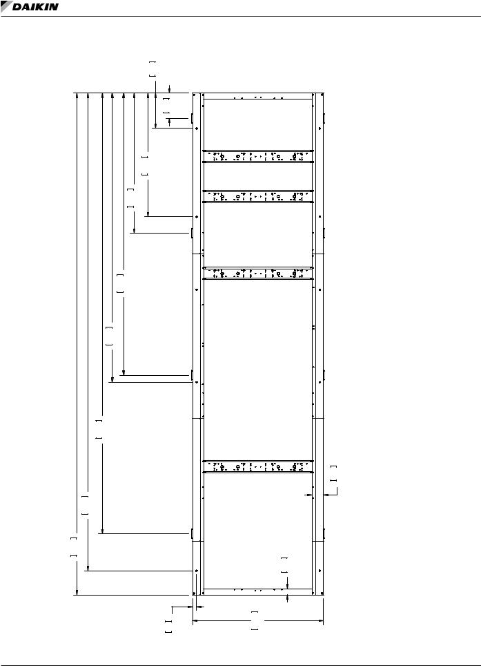
|
|
|
|
|
|
|
|
|
|
|
|
|
|
|
Lifting and Mounting Information |
Figure 26: 18 Fan Non-VFD Models |
|
|
|
|
|
|
|
|
|
||||||
|
|
|
|
|
|
|
600 |
23.6 |
|
|
|
|
|
|
|
|
|
|
|
|
|
|
|
|
|
|
CONTROLBOX |
|
|
||
|
|
|
|
|
|
|
|
431 |
17.0 |
L1 |
|
|
|
L2 |
|
|
|
|
|
|
|
|
|
|
|
M1 |
|
|
|
M2 |
|
|
|
|
|
|
|
2100 |
82.7 |
|
|
|
|
|
|
|
|
|
|
|
|
|
2381 |
93.7 |
|
|
|
M3 |
|
|
|
M4 |
|
|
|
|
|
|
|
|
|
|
|
|
|
|
|
L4 |
|
|
|
|
|
|
|
|
|
|
|
L3 |
|
|
|
|
|
|
|
|
|
4791 |
188.6 |
|
|
|
|
|
|
|
|
|
|
0A |
|
|
4910 |
193.3 |
|
|
|
|
|
|
|
|
|
|
|
330973505 |
|
|
|
|
|
|
|
|
|
M5 L5 |
|
|
|
M6 L6 |
|
DIM. DWG |
|
7484 |
294.6 |
|
|
|
|
|
|
|
|
|
|
|
|
AWS 18 FAN |
|
|
|
|
|
|
|
|
|
|
|
|
|
190 |
7.5 |
|
8110 |
319.3 |
|
|
|
|
|
|
|
|
|
|
|
|
|
|
|
|
|
|
|
|
|
|
|
L7 |
|
|
|
|
|
|
|
|
|
|
|
|
|
|
|
|
|
|
|
L8 |
|
8520 |
335.5 |
|
|
|
|
|
|
|
|
|
|
|
|
|
|
|
|
|
|
|
|
|
|
|
|
M7 |
|
100 |
3.9 |
M8 |
|
|
|
|
|
|
|
|
|
66 |
2.6 |
|
2225 |
87.6 |
|
|
|
IOM 1202-2 • PATHFINDER® MODEL AWS CHILLERS |
22 |
|
|
|
www.DaikinApplied.com |
||||||||||

com.DaikinApplied.www
23
CHILLERS AWS MODEL ®PATHFINDER • 2-1202 IOM
|
|
|
AWS 18 FAN DIM. DWG |
330973505 0A |
|
|
|
|
|
|
|
|
|
|
|
|
|
|
|
|
|
||||
|
|
|
|
|
|
|
|
|
|||||||||||||||||
|
AWS DIMENSIONAL DATA - WEIGHTS IN LBS. |
|
|
|
LIFTING WEIGHT FOR EACH POINT LB |
MOUNTING LOADS FOR EACH POINT LB |
|||||||||||||||||||
|
|
|
|
|
|
|
|
|
|
|
|
|
|
|
|
|
|
|
|
|
|
|
|
|
|
UNIT SIZE |
VOLTAGE |
HZ. |
STARTER |
SHIPPING |
OPERATING |
COPPER |
# OF |
L1 |
L2 |
L3 |
L4 |
L5 |
L6 |
L7 |
L8 |
M1 |
M2 |
M3 |
M4 |
M5 |
M6 |
M7 |
M8 |
||
WEIGHT |
WEIGHT |
FIN ADD |
FANS |
||||||||||||||||||||||
|
|
|
|
|
|
|
|
|
|
|
|
|
|
|
|
|
|
|
|
|
|
|
|
||
AWS214CDP |
400V - 50HZ |
WYE DELTA |
17527 |
18329 |
|
|
|
2826 |
2737 |
2476 |
2398 |
2043 |
1979 |
1559 |
1510 |
3009 |
2914 |
2702 |
2617 |
2127 |
2060 |
1473 |
1427 |
||
|
|
|
|
|
|
|
|
|
|
|
|
|
|
|
|
|
|
|
|
|
|
|
|
||
AWS244CDP |
400V - 50HZ |
WYE DELTA |
19237 |
20420 |
|
|
|
3006 |
3006 |
2655 |
2655 |
2221 |
2221 |
1736 |
1736 |
3257 |
3257 |
2940 |
2940 |
2345 |
2345 |
1668 |
1668 |
||
|
|
|
|
|
|
|
|
|
|
|
|
|
|
|
|
|
|
|
|
|
|
|
|
|
|
|
380-575V |
- 60HZ |
SOLID STATE |
17829 |
18631 |
|
|
|
2944 |
2839 |
2550 |
2459 |
2063 |
1989 |
1519 |
1465 |
3121 |
3009 |
2784 |
2684 |
2151 |
2074 |
1430 |
1379 |
|
|
|
|
|
|
|
|
|
||||||||||||||||||
AWS265CDP |
208-230V |
- 60HZ |
WYE DELTA |
2679 |
|
18 |
|||||||||||||||||||
|
|
|
|
|
|
|
|
|
|
|
|
|
|
|
|
|
|
|
|||||||
|
|
|
|
|
|
|
|
|
|
|
|
|
|
|
|
|
|
|
|
|
|
|
|
||
|
380-575V |
- 60HZ |
WYE DELTA |
17527 |
18329 |
|
2826 |
2737 |
2476 |
2398 |
2043 |
1979 |
1559 |
1510 |
3009 |
2914 |
2702 |
2617 |
2127 |
2060 |
1473 |
1427 |
|||
|
|
|
|
||||||||||||||||||||||
|
|
|
|
|
|
|
|
|
|
|
|
|
|
|
|
|
|
|
|
|
|
|
|
|
|
|
380-575V |
- 60HZ |
SOLID STATE |
19539 |
20722 |
|
|
|
3115 |
3115 |
2723 |
2723 |
2237 |
2237 |
1694 |
1694 |
3361 |
3361 |
3014 |
3014 |
2363 |
2363 |
1622 |
1622 |
|
|
|
|
|
|
|
|
|
||||||||||||||||||
AWS290CDP |
208-230V |
- 60HZ |
WYE DELTA |
|
|
|
|||||||||||||||||||
|
|
|
|
|
|
|
|
|
|
|
|
|
|
|
|
|
|
|
|
|
|||||
|
|
|
|
|
|
|
|
|
|
|
|
|
|
|
|
|
|
|
|
|
|
|
|
|
|
|
380-575V |
- 60HZ |
WYE DELTA |
19237 |
20420 |
|
|
|
3006 |
3006 |
2655 |
2655 |
2221 |
2221 |
1736 |
1736 |
3257 |
3257 |
2940 |
2940 |
2345 |
2345 |
1668 |
1668 |
|
|
|
|
|
|
|
|
|
|
|
|
|
|
|
|
|
|
|
|
|
|
|
|
|
||
|
|
|
|
|
|
|
|||||||||||||||||||
|
AWS DIMENSIONAL DATA - WEIGHTS IN KG. |
|
|
|
LIFTING WEIGHT FOR EACH POINT KG |
MOUNTING LOADS FOR EACH POINT KG |
|||||||||||||||||||
|
|
|
|
|
|
|
|
|
|
|
|
|
|
|
|
|
|
|
|
|
|
||||
UNIT SIZE |
VOLTAGE |
HZ. |
SHIPPING |
SHIPPING |
OPERATING |
COPPER |
# OF |
L1 |
L2 |
L3 |
L4 |
L5 |
L6 |
L7 |
L8 |
M1 |
M2 |
M3 |
M4 |
M5 |
M6 |
M7 |
M8 |
||
WEIGHT |
WEIGHT |
WEIGHT |
FIN ADD |
FANS |
|||||||||||||||||||||
|
|
|
|
|
|
|
|
|
|
|
|
|
|
|
|
|
|
|
|
|
|
|
|
||
AWS214CDP |
400V - 50HZ |
WYE DELTA |
7950 |
8314 |
|
|
|
1282 |
1241 |
1123 |
1088 |
927 |
898 |
707 |
685 |
1365 |
1322 |
1226 |
1187 |
965 |
935 |
668 |
647 |
||
|
|
|
|
|
|
|
|
|
|
|
|
|
|
|
|
|
|
|
|
|
|
|
|
||
AWS244CDP |
400V - 50HZ |
WYE DELTA |
8726 |
9262 |
|
|
|
1363 |
1363 |
1204 |
1204 |
1008 |
1008 |
788 |
788 |
1477 |
1477 |
1333 |
1333 |
1064 |
1064 |
757 |
757 |
||
|
|
|
|
|
|
|
|
|
|
|
|
|
|
|
|
|
|
|
|
|
|
|
|
|
|
|
380-575V |
- 60HZ |
SOLID STATE |
8087 |
8451 |
|
|
|
1336 |
1288 |
1157 |
1115 |
936 |
902 |
689 |
664 |
1416 |
1365 |
1263 |
1217 |
976 |
941 |
649 |
625 |
|
|
|
|
|
|
|
|
|
||||||||||||||||||
AWS265CDP |
208-230V |
- 60HZ |
WYE DELTA |
1215 |
|
18 |
|||||||||||||||||||
|
|
|
|
|
|
|
|
|
|
|
|
|
|
|
|
|
|
|
|||||||
|
|
|
|
|
|
|
|
|
|
|
|
|
|
|
|
|
|
|
|
|
|
|
|
||
|
380-575V |
- 60HZ |
WYE DELTA |
7950 |
8314 |
|
1282 |
1241 |
1123 |
1088 |
927 |
898 |
707 |
685 |
1365 |
1322 |
1226 |
1187 |
965 |
935 |
668 |
647 |
|||
|
|
|
|
||||||||||||||||||||||
|
|
|
|
|
|
|
|
|
|
|
|
|
|
|
|
|
|
|
|
|
|
|
|
|
|
|
380-575V |
- 60HZ |
SOLID STATE |
8863 |
9399 |
|
|
|
1413 |
1413 |
1235 |
1235 |
1015 |
1015 |
769 |
769 |
1525 |
1525 |
1367 |
1367 |
1072 |
1072 |
736 |
736 |
|
|
|
|
|
|
|
|
|
||||||||||||||||||
AWS290CDP |
208-230V |
- 60HZ |
WYE DELTA |
|
|
|
|||||||||||||||||||
|
|
|
|
|
|
|
|
|
|
|
|
|
|
|
|
|
|
|
|
|
|||||
|
|
|
|
|
|
|
|
|
|
|
|
|
|
|
|
|
|
|
|
|
|
|
|
|
|
|
380-575V |
- 60HZ |
WYE DELTA |
8726 |
9262 |
|
|
|
1363 |
1363 |
1204 |
1204 |
1008 |
1008 |
788 |
788 |
1477 |
1477 |
1333 |
1333 |
1064 |
1064 |
757 |
757 |
|
|
|
|
|
|
|
|
|
|
|
|
|
|
|
|
|
|
|
|
|
|
|
|
|
|
|
(continued) Models VFD-Non Fan 18 27: Figure
nformationI ountingM and iftingL
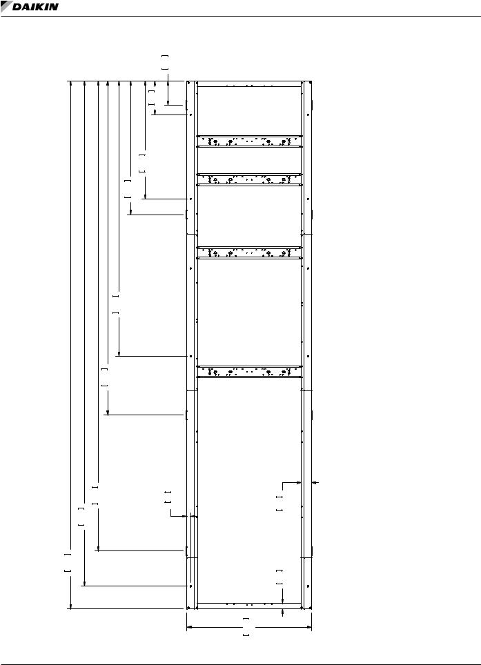
|
|
|
|
|
|
|
|
|
|
|
|
|
Lifting and Mounting Information |
Figure 28: 20 Fan Non-VFD Models |
|
|
|
|
|
|
|
|
|||||
|
|
|
|
|
|
|
|
431 |
17.0 |
CONTROLBOX |
|||
|
|
|
|
|
|
|
|
|
|
|
|||
|
|
|
|
|
|
600 |
23.6 |
|
|
L1 |
|
|
L2 |
|
|
|
|
|
|
|
|
|
|
M1 |
|
|
M2 |
|
|
|
|
|
2100 |
82.7 |
|
|
|
|
|
|
|
|
|
|
|
2381 |
93.7 |
|
|
|
|
M3 |
|
|
M4 |
|
|
|
|
|
|
|
|
|
|
L3 |
|
|
L4 |
|
|
|
|
|
|
|
|
|
|
|
|
|
|
0A |
|
|
4910 |
193.3 |
|
|
|
|
|
|
|
|
|
330973506 |
|
|
|
|
|
|
|
|
|
M5 |
|
|
M6 |
DWG |
|
|
5961 234.7 |
|
|
|
|
|
|
L5 |
|
|
|
DIM. |
|
|
|
|
|
|
|
|
|
|
|
L6 |
|
FAN |
|
|
|
|
|
|
|
|
|
|
|
|
|
AWS 20 |
|
|
|
|
|
|
|
|
|
|
|
|
|
|
|
8384 |
330.1 |
|
|
|
|
66 |
2.6 |
|
190 |
7.5 |
|
|
9010 |
354.7 |
|
|
|
|
|
|
|
|
|
|
|
|
|
|
|
|
|
|
|
|
|
L7 |
|
|
|
9421 |
370.9 |
|
|
|
|
|
|
|
|
|
|
|
L8 |
|
|
|
|
|
|
|
|
|
|
M7 |
|
100 |
3.9 |
|
|
|
|
|
|
|
|
|
|
|
|
|
M8 |
|
|
|
|
|
|
|
|
|
|
|
2225 |
87.6 |
|
IOM 1202-2 • PATHFINDER® MODEL AWS CHILLERS |
24 |
www.DaikinApplied.com |
|||||||||||

com.DaikinApplied.www
25
CHILLERS AWS MODEL ®PATHFINDER • 2-1202 IOM
|
|
|
|
|
|
AWS 20 FAN DIM. DWG |
330973506 |
0A |
|
|
|
|
|
|
|
|
|
|
|
|
|
|||||||
|
|
|
|
|
|
|
|
|
|
|||||||||||||||||||
|
AWS DIMENSIONAL DATA - WEIGHTS IN LBS. |
|
|
|
LIFTING WEIGHT FOR EACH POINT LB |
MOUNTING LOADS FOR EACH POINT LB |
||||||||||||||||||||||
|
|
|
|
|
|
|
|
|
|
|
|
|
|
|
|
|
|
|
|
|
|
|
|
|
|
|
||
UNIT SIZE |
VOLTAGE |
HZ. |
STARTER |
SHIPPING |
OPERATING |
COPPER |
# OF |
L1 |
L2 |
|
L3 |
|
L4 |
L5 |
L6 |
L7 |
L8 |
M1 |
M2 |
M3 |
M4 |
M5 |
M6 |
M7 |
M8 |
|||
WEIGHT |
|
WEIGHT |
FIN ADD |
FANS |
|
|
||||||||||||||||||||||
|
|
|
|
|
|
|
|
|
|
|
|
|
|
|
|
|
|
|
|
|
|
|
|
|
||||
AWS264-284CDP |
400V - 50HZ |
WYE DELTA |
20124 |
|
21257 |
|
|
|
3278 |
3278 |
2893 |
2893 |
2185 |
2185 |
1706 |
1706 |
3223 |
3223 |
2984 |
2984 |
2537 |
2537 |
1884 |
1884 |
||||
|
|
|
|
|
|
|
|
|
|
|
|
|
|
|
|
|
|
|
|
|
|
|
|
|
||||
AWS294CDH |
400V - 50HZ |
WYE DELTA |
19139 |
|
19461 |
|
|
|
3463 |
3338 |
2944 |
2838 |
1991 |
1920 |
1347 |
1298 |
3256 |
3139 |
2927 |
2822 |
2312 |
2229 |
1414 |
1363 |
||||
|
|
|
|
|
|
|
|
|
|
|
|
|
|
|
|
|
|
|
|
|
|
|
|
|
|
|
|
|
|
380-575V |
- 60HZ |
SOLID STATE |
20426 |
|
21559 |
|
|
|
3385 |
3385 |
2965 |
2965 |
2193 |
2193 |
1671 |
1671 |
3321 |
3321 |
3057 |
3057 |
2562 |
2562 |
1839 |
1839 |
|||
|
|
|
|
|
|
|
|
|
||||||||||||||||||||
AWS310-330CDP |
208-230V |
- 60HZ |
WYE DELTA |
|
|
|
|
|||||||||||||||||||||
|
|
|
|
|
|
|
|
|
|
|
|
|
|
|
|
|
|
|
|
|
|
|
|
|||||
|
|
|
|
|
|
|
|
|
|
|
|
|
|
|
|
|
|
|
|
|
|
|
|
|
|
|||
|
380-575V |
- 60HZ |
WYE DELTA |
20124 |
|
21257 |
|
|
|
3278 |
3278 |
2893 |
2893 |
2185 |
2185 |
1706 |
1706 |
3223 |
3223 |
2984 |
2984 |
2537 |
2537 |
1884 |
1884 |
|||
|
|
|
|
|
|
|
|
|
|
|
|
|
|
|
|
|
|
|
|
|
|
|
|
|
||||
AWS314CDH |
400V - 50HZ |
WYE DELTA |
19846 |
|
20143 |
|
|
|
3592 |
3592 |
3031 |
3031 |
1999 |
1999 |
1301 |
1301 |
3367 |
3367 |
3009 |
3009 |
2338 |
2338 |
1358 |
1358 |
||||
|
|
|
|
|
|
|
|
|
|
|
|
|
|
|
|
|
|
|
|
|
|
|
|
|
||||
AWS314-334CDS |
400V - 50HZ |
WYE DELTA |
19164 |
|
19501 |
2968 |
|
20 |
3558 |
3558 |
2970 |
2970 |
1892 |
1892 |
1162 |
1162 |
3337 |
3337 |
2958 |
2958 |
2247 |
2247 |
1209 |
1209 |
||||
|
|
|
|
|
|
|
|
|
|
|
|
|
|
|
|
|
|
|
|
|
|
|
|
|
|
|||
AWS330CDH |
460-575V |
- 60HZ |
SOLID STATE |
19442 |
|
19764 |
|
|
|
3573 |
3445 |
3018 |
2910 |
1998 |
1927 |
1308 |
1262 |
3355 |
3235 |
3001 |
2893 |
2337 |
2253 |
1369 |
1320 |
|||
|
|
|
|
|
|
|
|
|
|
|
|
|
|
|
|
|
|
|
|
|
|
|
|
|
|
|
|
|
380-575V |
- 60HZ |
WYE DELTA |
19139 |
|
19461 |
|
|
|
3463 |
3338 |
2944 |
2838 |
1991 |
1920 |
1347 |
1298 |
3256 |
3139 |
2927 |
2822 |
2312 |
2229 |
1414 |
1363 |
||||
|
|
|
|
|
||||||||||||||||||||||||
|
|
|
|
|
|
|
|
|
|
|
|
|
|
|
|
|
|
|
|
|
|
|
|
|
|
|||
AWS350-375CDS |
460-575V |
- 60HZ |
SOLID STATE |
19466 |
|
19803 |
|
|
|
3666 |
3666 |
3043 |
3043 |
1899 |
1899 |
1124 |
1124 |
3434 |
3434 |
3030 |
3030 |
2272 |
2272 |
1166 |
1166 |
|||
|
|
|
|
|
|
|
|
|
|
|
|
|
|
|
|
|
|
|
|
|
|
|
|
|
||||
380-575V |
- 60HZ |
WYE DELTA |
19164 |
|
19501 |
|
|
|
3558 |
3558 |
2970 |
2970 |
1892 |
1892 |
1162 |
1162 |
3337 |
3337 |
2958 |
2958 |
2247 |
2247 |
1209 |
1209 |
||||
|
|
|
|
|
|
|
|
|
|
|
|
|
|
|
|
|
|
|
|
|
|
|
|
|
|
|||
AWS350CDH |
460-575V |
- 60HZ |
SOLID STATE |
20147 |
|
20444 |
|
|
|
3699 |
3699 |
3102 |
3102 |
2007 |
2007 |
1266 |
1266 |
3462 |
3462 |
3080 |
3080 |
2363 |
2363 |
1317 |
1317 |
|||
|
|
|
|
|
|
|
|
|
|
|
|
|
|
|
|
|
|
|
|
|
|
|
|
|
|
|
|
|
380-575V |
- 60HZ |
WYE DELTA |
19846 |
|
20143 |
|
|
|
3592 |
3592 |
3031 |
3031 |
1999 |
1999 |
1301 |
1301 |
3367 |
3367 |
3009 |
3009 |
2338 |
2338 |
1358 |
1358 |
||||
|
|
|
|
|
||||||||||||||||||||||||
|
|
|
|
|
|
|
|
|
|
|
|
|
|
|
|
|
|
|
|
|
|
|
|
|||||
|
|
|
|
|
|
|
|
|||||||||||||||||||||
|
AWS DIMENSIONAL DATA - WEIGHTS IN KG. |
|
|
|
LIFTING WEIGHT FOR EACH POINT KG |
MOUNTING LOADS FOR EACH POINT KG |
||||||||||||||||||||||
|
|
|
|
|
|
|
|
|
|
|
|
|
|
|
|
|
|
|
|
|
|
|
|
|||||
UNIT SIZE |
VOLTAGE |
HZ. |
STARTER |
SHIPPING |
OPERATING |
COPPER |
# OF |
L1 |
L2 |
|
L3 |
|
L4 |
L5 |
L6 |
L7 |
L8 |
M1 |
M2 |
M3 |
M4 |
M5 |
M6 |
M7 |
M8 |
|||
WEIGHT |
|
WEIGHT |
FIN ADD |
FANS |
|
|
||||||||||||||||||||||
|
|
|
|
|
|
|
|
|
|
|
|
|
|
|
|
|
|
|
|
|
|
|
|
|
||||
AWS264-284CDP |
400V - 50HZ |
WYE DELTA |
9128 |
|
9642 |
|
|
|
1487 |
1487 |
1312 |
1312 |
991 |
991 |
774 |
774 |
1462 |
1462 |
1354 |
1354 |
1151 |
1151 |
855 |
855 |
||||
|
|
|
|
|
|
|
|
|
|
|
|
|
|
|
|
|
|
|
|
|
|
|
|
|
||||
AWS294CDH |
400V - 50HZ |
WYE DELTA |
8682 |
|
8827 |
|
|
|
1571 |
1514 |
1335 |
1287 |
903 |
871 |
611 |
589 |
1477 |
1424 |
1328 |
1280 |
1049 |
1011 |
641 |
618 |
||||
|
|
|
|
|
|
|
|
|
|
|
|
|
|
|
|
|
|
|
|
|
|
|
|
|
|
|
|
|
|
380-575V |
- 60HZ |
SOLID STATE |
9265 |
|
9779 |
|
|
|
1535 |
1535 |
1345 |
1345 |
995 |
995 |
758 |
758 |
1506 |
1506 |
1387 |
1387 |
1162 |
1162 |
834 |
834 |
|||
|
|
|
|
|
|
|
|
|
||||||||||||||||||||
AWS310-330CDP |
208-230V |
- 60HZ |
WYE DELTA |
|
|
|
|
|||||||||||||||||||||
|
|
|
|
|
|
|
|
|
|
|
|
|
|
|
|
|
|
|
|
|
|
|
|
|||||
|
|
|
|
|
|
|
|
|
|
|
|
|
|
|
|
|
|
|
|
|
|
|
|
|
|
|||
|
380-575V |
- 60HZ |
WYE DELTA |
9128 |
|
9642 |
|
|
|
1487 |
1487 |
1312 |
1312 |
991 |
991 |
774 |
774 |
1462 |
1462 |
1354 |
1354 |
1151 |
1151 |
855 |
855 |
|||
|
|
|
|
|
|
|
|
|
|
|
|
|
|
|
|
|
|
|
|
|
|
|
|
|
||||
AWS314CDH |
400V - 50HZ |
WYE DELTA |
9002 |
|
9137 |
|
|
|
1630 |
1630 |
1375 |
1375 |
907 |
907 |
590 |
590 |
1527 |
1527 |
1365 |
1365 |
1060 |
1060 |
616 |
616 |
||||
|
|
|
|
|
|
|
|
|
|
|
|
|
|
|
|
|
|
|
|
|
|
|
|
|
||||
AWS314-334CDS |
400V - 50HZ |
WYE DELTA |
8693 |
|
8846 |
1346 |
|
20 |
1614 |
1614 |
1347 |
1347 |
858 |
858 |
527 |
527 |
1514 |
1514 |
1342 |
1342 |
1019 |
1019 |
549 |
549 |
||||
|
|
|
|
|
|
|
|
|
|
|
|
|
|
|
|
|
|
|
|
|
|
|
|
|
|
|||
AWS330CDH |
460-575V |
- 60HZ |
SOLID STATE |
8819 |
|
8965 |
|
|
|
1621 |
1563 |
1369 |
1320 |
906 |
874 |
594 |
572 |
1522 |
1467 |
1361 |
1312 |
1060 |
1022 |
621 |
599 |
|||
|
|
|
|
|
|
|
|
|
|
|
|
|
|
|
|
|
|
|
|
|
|
|
|
|
|
|
|
|
380-575V |
- 60HZ |
WYE DELTA |
8682 |
|
8827 |
|
|
|
1571 |
1514 |
1335 |
1287 |
903 |
871 |
611 |
589 |
1477 |
1424 |
1328 |
1280 |
1049 |
1011 |
641 |
618 |
||||
|
|
|
|
|
||||||||||||||||||||||||
|
|
|
|
|
|
|
|
|
|
|
|
|
|
|
|
|
|
|
|
|
|
|
|
|
|
|||
AWS350-375CDS |
460-575V |
- 60HZ |
SOLID STATE |
8830 |
|
8983 |
|
|
|
1663 |
1663 |
1380 |
1380 |
861 |
861 |
510 |
510 |
1558 |
1558 |
1374 |
1374 |
1030 |
1030 |
529 |
529 |
|||
|
|
|
|
|
|
|
|
|
|
|
|
|
|
|
|
|
|
|
|
|
|
|
|
|
||||
380-575V |
- 60HZ |
WYE DELTA |
8693 |
|
8846 |
|
|
|
1614 |
1614 |
1347 |
1347 |
858 |
858 |
527 |
527 |
1514 |
1514 |
1342 |
1342 |
1019 |
1019 |
549 |
549 |
||||
|
|
|
|
|
|
|
|
|
|
|
|
|
|
|
|
|
|
|
|
|
|
|
|
|
|
|||
AWS350CDH |
460-575V |
- 60HZ |
SOLID STATE |
9139 |
|
9273 |
|
|
|
1678 |
1678 |
1407 |
1407 |
910 |
910 |
574 |
574 |
1571 |
1571 |
1397 |
1397 |
1072 |
1072 |
597 |
597 |
|||
|
|
|
|
|
|
|
|
|
|
|
|
|
|
|
|
|
|
|
|
|
|
|
|
|
|
|
|
|
380-575V |
- 60HZ |
WYE DELTA |
9002 |
|
9137 |
|
|
|
1630 |
1630 |
1375 |
1375 |
907 |
907 |
590 |
590 |
1527 |
1527 |
1365 |
1365 |
1060 |
1060 |
616 |
616 |
||||
|
|
|
|
|
||||||||||||||||||||||||
|
|
|
|
|
|
|
|
|
|
|
|
|
|
|
|
|
|
|
|
|
|
|
|
|
|
|
|
|
(continued) Models VFD-Non Fan 20 29: Figure
nformationI ountingM and iftingL
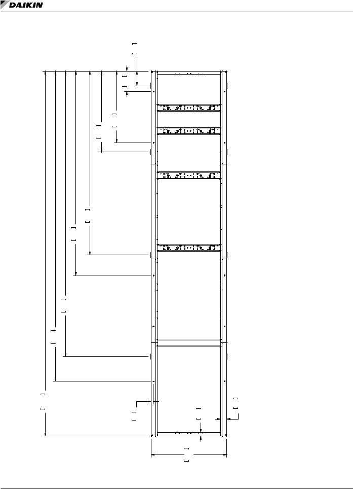
|
|
|
|
|
|
|
|
|
|
|
|
|
Lifting and Mounting Information |
Figure 30: 22 Fan Non-VFD Models |
|
|
|
|
|
|
|
|
|||||
|
|
|
|
|
|
|
|
431 |
17.0 |
|
|
|
|
|
|
|
|
|
|
|
|
|
|
CONTROLBOX |
|
||
|
|
|
|
|
|
|
600 |
23.6 |
L1 |
|
|
L2 |
|
|
|
|
|
|
|
|
|
|
M1 |
|
|
M2 |
|
|
|
|
|
|
|
2100 |
82.7 |
|
|
|
|
|
|
|
|
|
|
|
2381 |
93.7 |
|
|
M3 |
|
|
M4 |
|
|
|
|
|
|
|
|
|
|
|
|
|
L4 |
|
|
|
|
|
|
|
|
|
|
L3 |
|
|
|
|
|
|
|
|
5401 |
212.6 |
|
|
|
|
|
|
|
|
0A |
|
|
6000 |
236.2 |
|
|
|
|
|
|
|
|
|
330973507 |
|
|
|
|
|
|
|
|
L5 |
|
|
L6 |
|
DWG |
|
|
|
|
|
|
|
|
M5 |
|
|
M6 |
|
22 FAN DIM. |
|
8384 |
330.1 |
|
|
|
|
|
|
|
|
|
|
AWS |
|
|
|
|
|
|
|
|
|
|
|
|
|
|
9110 |
358.7 |
|
|
|
|
|
|
|
|
|
|
|
|
|
|
|
|
|
|
|
|
L7 |
|
|
L8 |
|
|
|
|
|
|
|
|
|
|
|
|
|
|
|
|
|
|
|
|
|
|
|
|
M7 |
|
|
M8 |
|
10720 |
422.0 |
|
|
|
|
|
|
|
|
|
|
190 |
7.5 |
|
|
|
|
|
|
|
|
66 |
2.6 |
|
100 |
3.9 |
|
|
|
|
|
|
|
|
|
|
|
2225 |
87.6 |
|
|
IOM 1202-2 • PATHFINDER® MODEL AWS CHILLERS |
26 |
|
|
www.DaikinApplied.com |
|||||||||

com.DaikinApplied.www
27
CHILLERS AWS MODEL ®PATHFINDER • 2-1202 IOM
|
|
|
AWS 22 FAN DIM. DWG |
330973507 0A |
|
|
|
|
|
|
|
|
|
|
|
|
|
|
|
||||||
|
|
|
|
|
|
|
|
|
|
|
|
|
|
|
|||||||||||
|
AWS DIMENSIONAL DATA - WEIGHTS IN LBS. |
|
|
|
|
LIFTING WEIGHT FOR EACH POINT LB |
|
|
MOUNTING LOADS FOR EACH POINT LB |
|
|||||||||||||||
UNIT SIZE |
VOLTAGE |
HZ. |
STARTER |
SHIPPING |
OPERATING |
COPPER |
# OF |
L1 |
|
L2 |
L3 |
L4 |
L5 |
L6 |
L7 |
L8 |
M1 |
M2 |
M3 |
M4 |
M5 |
M6 |
M7 |
M8 |
|
WEIGHT |
WEIGHT |
|
FIN ADD |
FANS |
|
||||||||||||||||||||
|
|
|
|
|
|
|
|
|
|
|
|
|
|
|
|
|
|
|
|
|
|
||||
AWS314CDP |
400V - 50HZ |
WYE DELTA |
22264 |
23357 |
|
|
|
3162 |
|
3063 |
2987 |
2893 |
2715 |
2629 |
2446 |
2369 |
3577 |
3465 |
3339 |
3234 |
2721 |
2635 |
2228 |
2157 |
|
|
|
|
|
|
|
|
|
|
|
|
|
|
|
|
|
|
|
|
|
|
|
|
|
|
|
AWS344CDH |
400V - 50HZ |
WYE DELTA |
21312 |
21563 |
|
|
|
3266 |
|
3251 |
2953 |
2940 |
2469 |
2458 |
1991 |
1982 |
3498 |
3482 |
3188 |
3174 |
2382 |
2371 |
1738 |
1730 |
|
|
|
|
|
|
|
|
|
|
|
|
|
|
|
|
|
|
|
|
|
|
|
|
|
|
|
AWS365CDP |
460-575V - 60HZ |
SOLID STATE |
22566 |
23659 |
|
3256 |
22 |
3271 |
|
3168 |
3058 |
2962 |
2730 |
2644 |
2405 |
2329 |
3682 |
3566 |
3418 |
3311 |
2733 |
2647 |
2186 |
2117 |
|
|
|
|
|
|
|
|
|
|
|
|
|
|
|
|
|
|
|
|
|
|
|
||||
380-575V - 60HZ |
WYE DELTA |
22264 |
23357 |
|
3162 |
|
3063 |
2987 |
2893 |
2715 |
2629 |
2446 |
2369 |
3577 |
3465 |
3339 |
3234 |
2721 |
2635 |
2228 |
2157 |
||||
|
|
|
|
|
|
|
|
|
|
|
|
|
|
|
|
|
|
|
|
|
|
|
|
|
|
AWS390CDH |
460-575V - 60HZ |
SOLID STATE |
21613 |
21864 |
|
|
|
3371 |
|
3356 |
3023 |
3009 |
2485 |
2473 |
1952 |
1944 |
3598 |
3581 |
3263 |
3249 |
2394 |
2384 |
1701 |
1694 |
|
|
|
|
|
|
|
|
|
|
|
|
|
|
|
|
|
|
|
|
|
|
|
|
|
||
380-575V - 60HZ |
WYE DELTA |
21312 |
21563 |
|
|
|
3266 |
|
3251 |
2953 |
2940 |
2469 |
2458 |
1991 |
1982 |
3498 |
3482 |
3188 |
3174 |
2382 |
2371 |
1738 |
1730 |
||
|
|
|
|
|
|
|
|
|
|
|
|
|
|
|
|
|
|
|
|
|
|
|
|
|
|
|
|
|
|
|
|
|
|
|
|
|
|||||||||||||||
|
AWS DIMENSIONAL DATA - WEIGHTS IN KG. |
|
|
|
|
LIFTING WEIGHT FOR EACH POINT KG |
|
|
MOUNTING LOADS FOR EACH POINT KG |
|
|||||||||||||||
|
|
|
|
|
|
|
|
|
|
|
|
|
|
|
|
|
|
|
|
|
|
|
|||
UNIT SIZE |
VOLTAGE |
HZ. |
STARTER |
SHIPPING |
OPERATING |
COPPER |
# OF |
L1 |
|
L2 |
L3 |
L4 |
L5 |
L6 |
L7 |
L8 |
M1 |
M2 |
M3 |
M4 |
M5 |
M6 |
M7 |
M8 |
|
WEIGHT |
WEIGHT |
|
FIN ADD |
FANS |
|
||||||||||||||||||||
|
|
|
|
|
|
|
|
|
|
|
|
|
|
|
|
|
|
|
|
|
|
||||
|
|
|
|
|
|
|
|
|
|
|
|
|
|
|
|
|
|
|
|
|
|
|
|
|
|
AWS314CDP |
400V - 50HZ |
WYE DELTA |
10099 |
10595 |
|
|
|
1434 |
|
1389 |
1355 |
1312 |
1231 |
1193 |
1109 |
1075 |
1623 |
1572 |
1515 |
1467 |
1234 |
1195 |
1010 |
979 |
|
AWS344CDH |
400V - 50HZ |
WYE DELTA |
9667 |
9781 |
|
|
|
1481 |
|
1475 |
1340 |
1334 |
1120 |
1115 |
903 |
899 |
1587 |
1580 |
1446 |
1439 |
1080 |
1075 |
789 |
785 |
|
|
|
|
|
|
|
|
|
|
|
|
|
|
|
|
|
|
|
|
|
|
|
|
|
|
|
AWS365CDP |
460-575V - 60HZ |
SOLID STATE |
10236 |
10732 |
|
1477 |
22 |
1484 |
|
1437 |
1387 |
1344 |
1238 |
1199 |
1091 |
1056 |
1670 |
1618 |
1550 |
1502 |
1240 |
1201 |
992 |
960 |
|
380-575V - 60HZ |
WYE DELTA |
10099 |
10595 |
|
1434 |
|
1389 |
1355 |
1312 |
1231 |
1193 |
1109 |
1075 |
1623 |
1572 |
1515 |
1467 |
1234 |
1195 |
1010 |
979 |
||||
|
|
|
|
|
|||||||||||||||||||||
|
|
|
|
|
|
|
|
|
|
|
|
|
|
|
|
|
|
|
|
|
|
|
|
|
|
AWS390CDH |
460-575V - 60HZ |
SOLID STATE |
9804 |
9917 |
|
|
|
1529 |
|
1522 |
1371 |
1365 |
1127 |
1122 |
886 |
882 |
1632 |
1624 |
1480 |
1474 |
1086 |
1081 |
772 |
768 |
|
|
|
|
|
|
|
|
|
|
|
|
|
|
|
|
|
|
|
|
|
|
|
|
|
||
380-575V - 60HZ |
WYE DELTA |
9667 |
9781 |
|
|
|
1481 |
|
1475 |
1340 |
1334 |
1120 |
1115 |
903 |
899 |
1587 |
1580 |
1446 |
1439 |
1080 |
1075 |
789 |
785 |
||
|
|
|
|
|
|
|
|
|
|
|
|
|
|
|
|
|
|
|
|
|
|
|
|
|
|
(continued) Models VFD-Non Fan 22 31: Figure
nformationI ountingM and iftingL

|
|
|
|
|
|
|
|
|
|
|
|
|
|
Lifting and Mounting Information |
Figure 32: 24 Fan 2-Circuit Non-VFD Models |
|
|
|
|
||||||||||
|
|
|
|
|
|
|
|
|
|
|
CONTROLBOX |
|
||
|
|
|
|
|
|
|
600 |
23.6 |
431 |
17.0 |
L1 |
|
L2 |
|
|
|
|
|
|
|
|
|
|
|
|
M1 |
|
M2 |
|
|
|
|
|
|
|
2100 |
82.7 |
|
|
|
|
|
|
|
|
|
|
|
|
2381 |
93.7 |
|
|
|
|
M3 |
|
M4 |
|
|
|
|
|
|
|
|
|
|
|
|
L3 |
|
L4 |
|
|
|
|
|
5401 |
212.6 |
|
|
|
|
|
|
|
|
|
|
|
|
5949 |
234.2 |
|
|
|
|
|
|
|
|
|
0A |
|
|
|
|
|
|
|
|
|
|
|
M5 L5 |
|
M6 L6 |
330973508 |
|
|
|
8147 320.8 |
|
|
|
|
|
|
|
|
|
|
DIM. DWG |
|
|
|
|
|
|
|
|
|
|
|
|
|
|
AWS 24 FAN |
|
|
|
|
|
|
|
|
|
|
|
M7 |
|
M8 |
|
|
|
9962 |
392.2 |
|
|
|
|
|
|
|
|
|
|
|
|
10499 |
413.4 |
|
|
|
|
|
|
|
|
|
|
|
|
|
|
|
|
|
|
|
|
|
|
|
L7 |
|
L8 |
|
|
|
|
|
|
|
|
|
|
|
|
M9 |
|
M10 |
|
11620 |
457.5 |
|
|
|
|
|
|
|
|
|
|
100 |
3.9 |
|
|
|
|
|
|
|
|
|
|
|
66 |
2.6 |
|
|
|
|
|
|
|
|
|
|
|
|
|
|
|
|
190 |
7.5 |
|
|
|
|
|
|
|
|
|
|
|
2225 |
87.6 |
|
|
IOM 1202-2 • PATHFINDER® MODEL AWS CHILLERS |
28 |
|
www.DaikinApplied.com |
|||||||||||
Loading...