


AVPTC
AIR HANDLER
INSTALLATION INSTRUCTIONS
© 2011 - 2012 Goodman Manufacturing Company, L.P. 5151 San Felipe, Suite 500, Houston, TX 77056 www.goodmanmfg.com -or- www.amana-hac.com P/N: IO-346D Date: September 2012
THIS PRODUCT CONTAINS ELECTRONIC COMPONENTS WHICH REQUIRE A DEFINITE GROUND. PROVISIONS ARE MADE FOR CONNECTION OF THE GROUND. A DEDICATED GROUND FROM THE MAIN POWER SUPPLY OR AN EARTH GROUND MUST BE PROVIDED.
NOTICE
IF A “1 FLASH” ERROR CODE OR AN “EC” HTR TOO LARGE ERROR IS ENCOUNTERED ON STARTUP, VERIFY THAT THE ELECTRIC HEATER DIP
SWITCHES HAVE BEEN SET TO THE APPROPRIATE HEATER SIZE. SEE PAGES 12 AND 13 FOR THE DIP SWITCH SETTINGS AND HEATER KIT AIRFLOW DELIVERY.
INTRODUCTION
This booklet contains the installation and operating instructions for your air handler. All warnings and precautions within this booklet must be observed. Improper installation can result in unsatisfactory operation or dangerous conditions and void the warranty. Read this booklet and any instructions packaged with accessories prior to installation. Give this booklet to the user and explain its provisions. The user should retain this booklet for future reference.
NOTE: Upon start up in communicating mode the circuit board will display a “1 Flash” error code on the diagnostic LED and an “Ec” HTR TO LARGE error at the communicating display. This is an indication that the dip switches on the control board need to be configured in accordance with the Electric Heating Airflow Table on page 13 of this manual. Configuring the dip switches and resetting power to the unit will clear the error code.
ELECTROSTATIC DISCHARGE (ESD) PRECAUTIONS
NOTE: Discharge body’s static electricity before touching unit. An electrostatic discharge can adversely affect electrical components.
Use the following precautions during modular blower installation and servicing to protect the integrated control module from damage. By putting the modular blower, the control, and the person at the same electrostatic potential, these steps will help avoid exposing the integrated control module to electrostatic discharge. This procedure is applicable to both installed and uninstalled (ungrounded) blowers.
1.Disconnect all power to the blower. Do not touch the integrated control module or any wire connected to the control prior to discharging your body’s electrostatic charge to ground.
2.Firmly touch a clean, unpainted, metal surface of the modular blower near the control. Any tools held in a person’s hand during grounding will be discharged.
3.Service integrated control module or connecting wiring following the discharge process in step 2. Use caution not to recharge your body with static electricity; (i.e., do not move or shuffle your feet, do not touch ungrounded objects, etc.). If you come in contact with an ungrounded object, repeat step 2 before touching control or wires.
4.Discharge your body to ground before removing a new control from its container. Follow steps 1 through 3 if installing the control on a blower. Return any old or new controls to their containers before touching any ungrounded object.
IMPORTANT NOTE TO THE OWNER REGARDING PRODUCT
WARRANTY
Your warranty certificate is supplied as a separate document with the unit installed by your contractor. Read the limited warranty certificate carefully to determine what is and is not covered and keep the warranty certificate in a safe place. If you are unable to locate the warranty certificate please contact your installing contractor or contact customer service (877-254-4729) to obtain a copy.
IMPORTANT: To register your Goodman® brand unit, go to www.goodmanmfg.com and click “Warranty Registration”. Complete registration as prompted.
To register your Amana® brand unit, go to www.amanahac.com and click “Warranty Registration”. Complete registration as prompted.
Product limited warranty certificates for models currently in production can be viewed at www.goodmanmfg.com or www.amana-hac.com. If your model is not currently in production or does not appear on the website, please contact your installing contractor or contact customer service (877- 254-4729) to obtain a copy of your warranty certificate.
Each product overview page contains a Product Warranty link; by clicking on it you will be able to view the limited warranty coverage for that specific product. To view warranty registration information, click on the Product Warranty text on the left navigation panel on the home page of each website. The Online Product Registration pages are located in this same section.

CHECKING PRODUCT RECEIVED
Upon receiving the unit, inspect it for damage from shipment. Claims for damage, either shipping or concealed, should be filed immediately with the shipping company. Check the unit model number, specifications, electrical characteristics and accessories to determine if they are correct. In the event an incorrect unit is shipped, it must be returned to the supplier and must NOT be installed. The manufacturer assumes no responsibility for installation of incorrectly shipped units.
REPLACEMENT PARTS
ORDERING PARTS
When reporting shortages or damages, or ordering repair parts, give the complete unit model and serial numbers as stamped on the unit’s nameplate.
Replacement parts for this appliance are available through your contractor or local distributor. For the location of your nearest distributor, consult the white business pages, the yellow page section of the local telephone book or contact:
CONSUMER AFFAIRS
GOODMAN MANUFACTURING COMPANY, L.P.
7401 SECURITY WAY
HOUSTON, TEXAS 77040 877-254-4729
IMPORTANT SAFETY INSTRUCTIONS
RECOGNIZE SAFETY SYMBOLS, WORDS, AND LABELS
The following symbols and labels are used throughout this manual to indicate immediate or potential hazards. It is the owner’s responsibility to read and comply with all safety information and instructions accompanying these symbols. Failure to heed safety information increases the risk of property damage, product damage, personal injury or death.
 WARNING
HIGH VOLTAGE!
DISCONNECT ALL POWER BEFORE SERVICING.
MULTIPLE POWER SOURCES MAY BE PRESENT. FAILURE
TO DO SO MAY CAUSE PROPERTY DAMAGE, PERSONAL
INJURY OR DEATH.
 WARNING
ONLY INDIVIDUALS MEETING THE REQUIREMENTS OF AN “ENTRY LEVEL
TECHNICIAN”, AT A MINIMUM, AS SPECIFIED BY THE AIR
CONDITIONING, HEATING AND REFRIGERATION INSTITUTE (AHRI) MAY USE THIS INFORMATION. ATTEMPTING TO INSTALL OR REPAIR THIS UNIT WITHOUT SUCH BACKGROUND MAY RESULT IN PRODUCT DAMAGE,
PERSONAL INJURY, OR DEATH.
To avoid property damage, personal injury or death due to electrical shock, this unit MUST have an uninterrupted, unbroken electrical ground. The electrical ground circuit may consist of an appropriately sized electrical wire connecting the ground lug in the unit control box to the building electrical service panel.
Other methods of grounding are permitted if performed in accordance with the National Electric Code (NEC)/American National Standards Institute (ANSI)/National Fire Protection Association (NFPA) 70 and local/state codes. In Canada, electrical grounding is to be in accordance with the Canadian Electric Code (CSA) C22.1.
This product is factory-shipped for use with 208/240/1/60 electrical power supply. DO NOT reconfigure this air handler to operate with any other power supply.
When installing or servicing this equipment, safety clothing, including hand and eye protection, is strongly recommended. If installing in an area that has special safety requirements (hard hats, etc.), observe these requirements.
Do not connect to or use any device that is not designcertified by Goodman for use with this unit. Serious property damage, personal injury, reduced unit performance and/or hazardous conditions may result from the use of such non-approved devices.
To prevent the risk of property damage, personal injury, or death, do not store combustible materials or use gasoline or other flammable liquids or vapors in the vicinity of this unit.
2

CARBON MONOXIDE POISONING HAZARD
Special Warning for Installation of Furnace or Air Handling Units in Enclosed Areas such as Garages, Utility Rooms or Parking Areas
Carbon monoxide producing devices (such as an automobile, space heater, gas water heater, etc.) should not be operated in enclosed areas
such as unventilated garages, utility rooms or parking areas because of the danger of carbon monoxide (CO) poisoning resulting from the exhaust emissions. If a furnace or air handler is installed in an enclosed area such as a garage, utility room or parking area and a carbon monoxide producing device is operated therein, there must be adequate, direct outside
ventilation.
This ventilation is necessary to avoid the danger of CO poisoning which can occur if a carbon monoxide producing device continues to operate in the enclosed area. Carbon monoxide emissions can be (re)circulated throughout the structure if the furnace or air handler is operating in any mode.
CO can cause serious illness including permanent brain damage or death.
B10259-216
-
CODES & REGULATIONS
This product is designed and manufactured to comply with national codes. Installation in accordance with such codes and/or prevailing local codes/regulations is the responsibility of the installer. The manufacturer assumes no responsibility for equipment installed in violation of any codes or regulations.
The United States Environmental Protection Agency (EPA) has issued various regulations regarding the introduction and disposal of refrigerants. Failure to follow these regulations may harm the environment and can lead to the imposition of substantial fines. Should you have any questions please contact the local office of the EPA.
If replacing an air handler, the system must be manufacturer approved and Air Conditioning, Heating and Refrigeration Institute (AHRI) matched. NOTE: Installation of unmatched systems is strongly discouraged.
FEATURES
This air handler is a part of the ComfortNet™ family of products. It may be installed as part of a “non-communicating” system using a standard 24 VAC thermostat. However, with the CTK0*AA ComfortNet thermostat kit, this air handler may be installed as part of a digitally communicating system. The ComfortNet system provides automatic airflow configuration, enhanced setup features, and enhanced diagnostics. It also reduces the number of thermostat wires to a maximum of four and a minimum of two.
PRE-INSTALLATION INSTRUCTIONS
Carefully read all instructions for the installation prior to installing product. Make sure each step or procedure is understood and any special considerations are taken into account before starting installation. Assemble all tools, hardware and supplies needed to complete the installation. Some items may need to be purchased locally. Make sure everything needed to install the product is on hand before starting.
LOCATION
NOTE: Air handlers are designed for indoor installation only.
Give special consideration to minimizing the length of refrigerant tubing when installing air handlers. Refer to Remote Cooling/Heat Pump Service Manual TP-107 Long Line Set Application R-410A for guidelines. The unit clearance from a combustible surface may be 0". However, service clearance is to take precedence. In addition allow a minimum of 24" in front of the unit for service clearance.
If the unit is located in an area with high ambient temperature and/or high humidity, the air handler may be subject to nuisance sweating of the casing. On these installations, a wrap of 2” fiberglass insulation with a vapor barrier is recommended.
Do not install the air handler in a location that violates the instructions provided with the condenser.
Consult all appropriate regulatory codes prior to determining final clearances. When installing this unit in an area that may become wet, elevate the unit with a sturdy, non-porous material. In installations that may lead to physical damage (i.e. a garage) it is advised to install a protective barrier to prevent such damage.
DUCTWORK
This air handler is designed for a complete supply and return ductwork system.
Do not operate this product without all the ductwork attached.
To ensure correct system performance, the ductwork is to be sized to accommodate 375-425 CFM per ton of cooling with the static pressure not to exceed .5" WC. Inadequate duct work that restricts airflow can result in improper performance and compressor or heater failure. Ductwork is to be constructed in a manner that limits restrictions and maintains suitable air velocity. Ductwork is to be sealed to the unit in a manner that will prevent leakage.
RETURN DUCTWORK
DO NOT TERMINATE THE RETURN DUCTWORK IN AN AREA THAT CAN INTRODUCE TOXIC, OR OBJECTIONABLE FUMES/ODORS INTO THE DUCTWORK. The return ductwork is to be introduced into the air handler bottom (upflow configuration).
3

RETURN AIR FILTERS
Each installation must include a return air filter. This filtering may be performed at the air handler or externally such as a return air filter grille. Air handlers mounted in the downflow orientation, including “B” series, require external filtering. A washable filter is available as an accessory. To ensure optimum performance frequent filter cleaning is advised. Refer to Air Filter Accessory table for the appropriate filter.
AVPTC |
Filter Number |
Qty Required |
|
|
|
|
|
1830 |
FIL 36-42 |
1 |
|
(19" x 21") |
|||
|
|
||
|
|
|
|
3137 |
FIL 48-61 |
1 |
|
4260 |
(21-1/2" x 23") |
||
|
|||
|
|
|
Air Filter Accessories
ELECTRIC HEAT
Refer to this manual in combination with the instructions provided with the heat kit for the correct installation procedure.
The air handlers listed in this manual do not have factory installed electric heat. Electric heat is available as an accessory. If installing this option, the ONLY heat kits that can be used are the HKR series.
NOTE: The Amana® brand EHK, ECB, EDB, and EDK kits are NOT approved for use with these air handlers.
HKR INSTALLATION
Follow instructions listed in Installation and Operating Instructions shipped with the heat kit.
ELECTRICAL SUPPLY WIRE AND MOP
FIRE HAZARD!
To avoid the risk of property damage, personal injury or fire, use only copper conductors.
HIGH VOLTAGE!
Disconnect ALL power before servicing. 


 Multiple power sources may be present.

 Failure to do so may cause property damage, personal injury or death.
HIGH VOLTAGE!
To avoid property damage, personal injury or death due to electrical shock, this unit MUST have an uninterrupted, unbroken electrical ground. The electrical ground circuit may consist of an appropriately sized electrical wire connecting the ground lug in the unit control box to the building electrical service panel.
Other methods of grounding are permitted if performed in accordance with the National Electric Code (NEC)/American National Standards Institute (ANSI)/National Fire Protection Association (NFPA) 70 and local/state codes. In Canada, electrical grounding is to be in accordance with the Canadian Electric Code (CSA) C22.1.
BUILDING ELECTRICAL SERVICE INSPECTION
This unit is designed for single-phase electrical supply. DO NOT OPERATE ON A THREE-PHASE POWER SUPPLY. Measure the power supply to the unit. The supply voltage must be in agreement with the unit nameplate power requirements and within the range specified below.
Power Supply Voltage
Nominal Input |
Minimum Voltage |
Maximum Voltage |
|
|
|
208/240 |
187 |
253 |
WIRE SIZING
Wire size is important to the operation of your equipment. Use the following check list when selecting the appropriate wire size for your unit.
•Wire size must carry the Minimum Circuit Ampacity (MCA).
•Refer to the NEC (USA) or CSA (Canada) for wire sizing. The unit MCA for the air handler and the optional electric heat kit can be found on the unit Series and Rating Plate.
•Wire size allows for no more than a 2% voltage drop from the building breaker/fuse panel to the unit.
Refer to the latest edition of the National Electric Code or in Canada the Canadian Electric Code when determining the correct wire size. The following table shows the current carrying capabilities for copper conductors rated at 75oC with a 2% voltage drop. Use the table below to determine the voltage drop per foot of various conductors.
4

Maximum Allowable Length in Feet to Limit Voltage Drop to 2%*
Wire Size |
|
Minimum Circuit Ampacity (MCA) |
|
||||||
(AWG) |
|
|
|
|
|
|
|
|
|
10 |
15 |
20 |
25 |
30 |
35 |
40 |
45 |
||
|
|||||||||
|
|
|
|
|
|
|
|
|
|
14 |
75 |
50 |
37 |
NR |
NR |
NR |
NR |
NR |
|
12 |
118 |
79 |
59 |
47 |
NR |
NR |
NR |
NR |
|
10 |
188 |
125 |
95 |
75 |
63 |
54 |
NR |
NR |
|
8 |
301 |
201 |
150 |
120 |
100 |
86 |
75 |
68 |
|
6 |
471 |
314 |
235 |
188 |
157 |
134 |
118 |
110 |
|
*Based on NEC 1996
MAXIMUM OVERCURRENT PROTECTION (MOP)
Every installation must include an NEC (USA) or CEC (Canada) approved overcurrent protection device. Also, check with local or state codes for any special regional requirements.
Protection can be in the form of fusing or HACR style circuit breakers. The Series and Rating Plate can be used as a guide for selecting the MAXIMUM overcurrent device.
NOTE: Fuses or circuit breakers are to be sized larger than the equipment MCA but not to exceed the MOP.
ELECTRICAL CONNECTIONS
Consult the local power company and local codes before installing this unit. All wiring must be in accordance with the National Electrical Code as well as all local codes. Knockouts have been provided on side and top of the cabinet for the installation of the electrical conduit. If the knockouts on the cabinet sides are used for electrical conduit, an adapter ring must be used in order to meet UL1995 safety requirements. Use Minimum Circuit Ampacity and type of wire to determine proper wire size. The unit MUST be properly grounded. A ground lug is provided in the unit.
Check all factory connections before connecting electrical power to unit to ensure none were loosened or disconnected during shipping and handling.
 WARNING
HIGH VOLTAGE!
TO PREVENT PERSONAL INJURY OR DEATH DUE TO
ELECTRICAL SHOCK, DISCONNECT THE ELECTRICAL
POWER BEFORE ELECTRICALLY CONNECTING THE UNIT.
 WARNING
TO AVOID THE RISK OF FIRE OR EQUIPMENT DAMAGE, USE COPPER CONDUCTORS.
 CAUTION
TO AVOID THE RISK OF PERSONAL INJURY, WIRING TO THE UNIT MUST BE PROPERLY POLARIZED AND GROUNDED.
 WARNING
ALL WIRING MUST COMPLY WITH APPLICABLE LOCAL AND NATIONAL CODES. TYPE AND LOCATION OF FUSED DISCONNECT SWITCH(ES) MUST COMPLY WITH ALL APPLICABLE CODES AND PROVIDE OVERCURRENT PROTECTION AS SHOWN ON THE NAMEPLATE.
208/230 VOLT LINE CONNECTIONS
If heater kits will not be installed, remove the proper size knockout for the electrical conduit connection. Connect electrical conduit to the unit using two washers to make an approved connection.
The power supply wires must be connected to the red and black power wiring. Two wire nuts are provided in the bag assembly for this connection. Wrap the wire nuts with electrical tape. (Insulated crimp type connectors, field supplied, may be substituted for the wire nuts and electrical tape provided proper size connectors are used.) A ground wire MUST be connected to the ground lug inside the unit.
AIR HANDLER ONLY (NON-HEAT KIT MODELS)
The building supply connects to the stripped black and red wires contained in the air handler electrical compartment cavity. A ground screw is also contained in this area. Attach the supply wires to the air handler conductors as shown in the unit wiring diagram using appropriately sized solderless connectors or other NEC or CEC approved means.
AIR HANDLER WITH NON-CIRCUIT BREAKER HEAT KITS
A terminal block is provided with the HKR kit to attach the power supply and air handler connections. Follow the HKR Installation Manual and wiring diagram for complete wiring details.
AIR HANDLER WITH HEAT KITS CONTAINING A CIRCUIT
BREAKER
HKR models with a “C” suffix contain a circuit breaker(s). The air handler has a plastic cover on the access panel that will require either one or both sections to be removed to allow the heat kit circuit breaker(s) to be installed. See the HKR Installation Instructions for further details. The air handler wires and supply wires are installed directly onto the HKR circuit breaker(s) as shown in the HKR Installation Manual and wiring diagram.
OPERATION ON 208 VOLT SUPPLY
The unit transformer is factory connected for 240 V operation. If unit is to operate on 208 V, disconnect the red wire from terminal 3 of the unit transformer and connect them to terminal 2 of the unit transformer.
LOW VOLTAGE WIRING
Low voltage wiring connections are made at the top of the cabinet. See the 24 Volt Thermostat Wiring section of this manual for typical low voltage wiring connections. A minimum 18 AWG wire must be used for installations up to 100 feet.
5

24 VOLT THERMOSTAT WIRING - NON-COMMUNICATING
THERMOSTAT CONNECTIONS
NOTE: Wire routing must not interfere with the circulator blower operation or routine maintenance.
The air handler’s integrated control module provides terminals for “Y1” and “Y2” and “W1” and “W2” thermostat connections. This allows the air handler to support the systems shown in the table below. Refer to the following figures for typical connections to the integrated control module. Thermostat wiring entrance holes are located in the top of the blower. Wire routing must not interfere with circulator blower operation or routine maintenance.
COOLING |
HEAT PUMP HEATING |
ELECTRIC HEATING |
|
|
|
|
|
|
1-STAGE |
------ |
1- or 2-STAGE |
2-STAGE |
------ |
1- or 2-STAGE |
1-STAGE |
1-STAGE |
------ |
2-STAGE |
2-STAGE |
------ |
1-STAGE |
1-STAGE |
1- or 2-STAGE |
2-STAGE |
2-STAGE |
1- or 2-STAGE |
NOTE: A removable plug connector is provided with the control to make thermostat wire connections. This plug may be removed, wire connections made to the plug, and replaced. It is strongly recommended that multiple wires into a single terminal be twisted together prior to inserting into the plug connector. Failure to do so may result in intermittent operation.
Typical Single-Stage Cool, |
Place Jumper Between Y1 |
||
Single-Stage Heat Thermostat |
|||
and O for Proper |
|||
|
|
||
|
|
Dehumidification Operation |
|
R C G W1 |
Y1 |
and Proper Ramping |
|
|
|
Profile Operation |
|
1 |
2 |
R |
C |
G |
W1 W2 |
Y1 |
Y2 |
O DEHUM |
Air Handler Integrated |
Control Module |
R C |
Y |
NEU |
Remote Condensing Unit |
HOT Dehumidistat |
|
|
(Single-Stage AC) |
[Optional] |
Typical Single-Stage Cooling with Single-Stage Heating
______________________________________
|
|
Typical Two-Stage Cool, |
|
Place Jumper Between Y1 |
|||||||
|
|
Two-Stage Heat Thermostat |
|||||||||
|
|
|
and O for Proper |
||||||||
|
|
|
|
|
|
|
|
|
|
||
|
|
R |
C G |
|
|
|
|
Dehumidification Operation |
|||
|
|
W1 |
W2 |
Y1 |
Y2 |
|
and Proper Ramping |
||||
|
|
|
|
|
|
|
|
|
|
Profile Operation |
|
1 |
2 |
R |
C |
G |
W1 |
W2 |
Y1 |
Y2 |
O |
|
Air Handler Integrated |
DEHUM |
Control Module |
||||||||||
R C |
Y1 Y2 |
NEU |
|
Remote Condensing Unit |
HOT |
Dehumidistat |
|
|
(Two-Stage AC) |
|
[Optional] |
Typical Two-Stage Cooling with Two-Stage Heating
R C G W/E |
Y1 |
O |
Typical Single-Stage Cool, |
Single-Stage Heat |
|||
|
|
|
Heat Pump Thermostat |
1 |
2 |
R |
C |
G W1 |
|
O DEHUM |
|
Air Handler |
W2 Y1 Y2 |
Integrated Control Module |
|||||||
|
|
R |
C |
W1 |
Y |
O |
NEU |
Dehumidistat |
|
|
|
|
|
|
|
||
|
|
|
Remote Condensing Unit |
|
HOT |
[Optional] |
||
|
|
|
|
|
||||
|
|
|
|
(Single-Stage HP) |
|
|
||
|
|
|
|
|
|
|
||
Typical Single-Stage Heat Pump with Auxiliary/Emergency Heating
______________________________________
|
|
R |
C G W/E W2 |
Y1 |
Y2 |
O |
Typical Two-Stage Cool, |
|||
|
|
|
Two-Stage Heat |
|||||||
|
|
|
|
|
|
|
|
Heat Pump Thermostat |
||
1 |
2 |
R |
C G W1 W2 Y1 |
|
O |
|
|
Air Handler |
||
Y2 |
DEHUM |
Integrated Control Module |
||||||||
|
|
R |
C |
W1 |
Y1 |
Y2 |
O |
|
NEU |
Dehumidistat |
|
|
|
|
|
|
|
|
|
||
|
|
|
Remote Condensing Unit |
|
|
HOT |
[Optional] |
|||
|
|
|
|
|
|
|||||
|
|
|
|
(Two-Stage HP) |
|
|
|
|
||
|
|
|
|
|
|
|
|
|
||
Typical Two Stage Heat Pump heating and Auxiliary/ Emergency Heating
24 VOLT DEHUMIDISTAT WIRING - NON-COMMUNICATING THERMOSTAT CONNECTIONS
The optional usage of a dehumidistat allows the air handler’s circulator blower to operate at a slightly lower speed during a combined thermostat call for cooling and dehumidistat call for dehumidification. This lower blower speed enhances dehumidification of the conditioned air as it passes through the AC coil. For proper function, a dehumidistat applied to this air handler must operate on 24 VAC and utilize a switch which opens on humidity rise.
To install/connect a dehumidistat:
1.Turn OFF power to air handler.
2.Secure the dehumidistat neutral wire (typically the white lead) to the screw terminal marked “DEHUM” on the air handler’s integrated control module.
3.Secure the dehumidistat hot wire (typically the black lead) to the screw terminal marked “R” on the air handler’s integrated control module.
4.Secure the dehumidistat ground wire (typically the green lead) to the ground screw on the air handler. NOTE: Ground wire may not be present on all dehumidistats.
5.Turn ON power to air handler.
6
To enable the dehumidification function, move the dehumidification dipswitch from OFF to ON. See following figure.
|
|
|
|
|
|
S7 |
S8 |
||||||
|
|
|
|
|
|
|
|
|
|
|
|
|
|
ON |
|
|
|
|
|
|
|
|
|
|
|
|
|
|
|
|
|
|
|
|
|
|
|
|
|
|
|
OFF |
|
|
|
|
|
|
|
|
|
|
|
|
|
|
|
|
|
|
|
|
|
|
|
|
|
|
|
|
|
|
|
|
|
|
|
|
|
|
|
|
|
|
|
|
|
|
|
|
|
|
|
|
|
|
|
position to enable |
|
|
DEHUM |
Unused |
|||||||||
Move to the ON |
|
|
|
|
|
|
|
|
|
|
|||
dehumidification |
|
|
|
|
|
|
|
|
|
|
|||
Dipswitches - Dehumidification Enable
REFRIGERANT LINES
This product is factory-shipped under pressure. Follow these instructions to prevent injury.
A quenching cloth is strongly recommended to prevent scorching or marring of the equipment finish when welding close to the painted surfaces. Use brazing alloy of 5% minimum silver content.
TUBING PREPARATION
All cut ends are to be round, burr free, and clean. Failure to follow this practice increases the chances for refrigerant leaks. The suction line is spun closed and requires pipe cutters to remove the closed end.
POST BRAZING
Quench all welded joints with water or a wet rag.
PIPING SIZE
For the correct tubing size, follow the specification for the condenser/heat pump.
SPECIAL INSTRUCTIONS
This coil comes equipped with a thermostatic expansion valve (TXV) for refrigerant management.
IMPORTANT NOTE: Torch heat required to braze tubes of various sizes is proportional to the size of the tube. Tubes of smaller size require less heat to bring the tube to brazing temperature before adding brazing alloy. Applying too much heat to any tube can melt the tube. Service personnel must use the appropriate heat level for the size of the tube being brazed.
NOTE: The use of a heat shield when brazing is recommended to avoid burning the serial plate or the finish on the unit. HEAT TRAP OR WET RAGS SHOULD BE USED TO PROTECT HEAT SENSITIVE COMPONENTS SUCH AS SERVICE VALVES AND TXV VALVES.
IMPORTANT NOTE: Sensing bulbs are not permanently installed at the factory to prevent accidental damage during brazing. Be sure to follow this checklist step-by- step to ensure the sensing bulb is not damaged during installation.
1.Loosen the 13/16 nut 1 TURN ONLY. No pressure loss indicates possible leak.
2.Remove the nut and discard the cap.
3.Follow the instructions on the caution label, and remove the two mounting screws on the lower access panel. Then remove the lower access panel.
4.Remove the large front panel and remove the sensing bulb from suction manifold. TO PREVENT DAMAGE TO SENSING BULB, ENSURE BULB IS NOT NEAR FLAME OR IN CONTACT WITH SUCTION LINE OR MANIFOLD DURING BRAZING.
5.Use a tube cutter to remove the spin closure on the suction line.
Excessive torque can cause orifices to stick. Use the proper torque settings when tightening orifices.
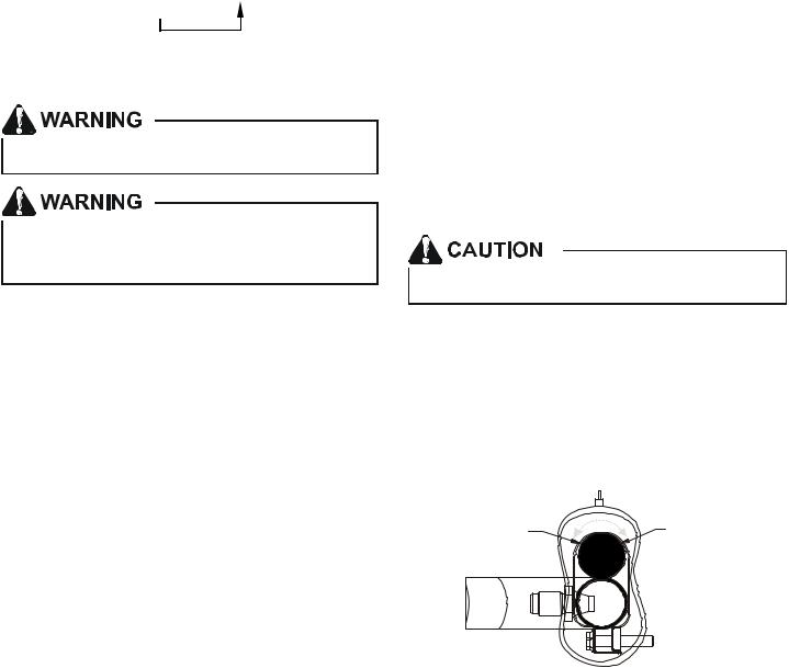
6.Replace sensing bulb to horizontal portion of suction line just inside cabinet. Place bulb parallel with suction line between 10 o’clock and 2 o’clock position. Secure bulb to line with strapping provided in literature envelope. Insulate sensing bulb to line with self-adhesive insulation provided in the envelope. See the following figures for correct bulb placement and strapping information.
REFRIGERANT BULB |
REFRIGERANT BULB |
MUST BE POSITIONED |
MUST BE POSITIONED |
BETWEEN 10 & 2 O’CLOCK |
BETWEEN 10 & 2 O’CLOCK |
NOTE: The sensing bulb must be permanently located. A heat shield, heat trap, or wet rag must be used during brazing to prevent damage to the TXV valve.
7

7.Replace access panels, suction line grommet, insulation and all screws.
SUCTION LINE
WITH SPIN CLOSURE 
RUBBER
 GROMMET
Suction Line Grommet
AIRFLOW CONVERSIONS
DOWNFLOW CONVERSION
Conversion to downflow MUST be performed in an area that allows access to all sides prior to placing the air handler in its final location. To prevent the evaporator coil pan from “sweating”, a drain pan insulation (DPI) accessory kit is to be used when performing this conversion. NOTE: The DPI kit is not supplied with this product and is to be purchased separately. See the following Drain Pan Insulation Kit table for the correct DPI kit.
AVPTC Model |
Insulation Kit |
|
|
|
|
1830 |
DPI36-42/20 |
|
|
|
|
3137 |
DPI48-61/-20 |
|
4260 |
||
|
Drain Pan Insulation Kits
Refer to Figures Downflow Conversion - Conversion Preparation, Downflow Conversion - Insulation Retainers, and Downflow Conversion - Conversion Completion for the location of the components referenced in the following steps. Figure Downflow Conversion - Conversion Preparation illustrates the new installation location for the removed components.
1.Before inverting the air handler, remove all access panels, the coil rear channel bracket, and the filter closeoff panel.
2.Remove the evaporator coil and the horizontal drain pan. Discard horizontal drain pan.
3.Install the provided plastic plug into the vacated access panel.
4.Remove the two (2) zee coil support brackets and insulation retaining brackets.
5.Remove the tie bracket.
6.Install the DPI Insulation Kit onto the bottom of the drain pan.
ACCESS PANEL 
RETURN AIR SIDE
 OF UNIT
REAR CHANNEL
BRACKET

 ZEE COIL
SUPPORT BRACKET


 COIL RETAINING BRACKET
TIE BRACKET
NOTE: The filter provision is not applicable in THIS downflow application.
Downflow Conversion - Conversion Preparation
7.Install the zee coil supports and the wrapper stiffeners.
8.Install the tie bracket.
9.Install the rear channel bracket.
10.To prevent possible condensate “blow off” the insulation retainers are to be laid into the evaporator coil pan as shown.
3” FLAT INSULATION RETAINER (BOTH SIDES)
Downflow Conversion - Insulation Retainers
To complete the conversion, slide the evaporator coil into the chassis and attach the three (3) access panels.
8
 Loading...