


Goodman ARPT18B14, ARPT24B14, ARPT30B14, ARPT36C14, ARPT36D14 Installation Manual
...ARUF**14**/ARPT**14** |
|
©2012 Goodman Manufacturing Company, L.P. |
|||
ASPT**14**/ASUF**14** |
|
5151 San Felipe, Suite 500, Houston, TX 77056 |
|||
AIR HANDLERS |
|
www.goodmanmfg.com - or - www.amana-hac.com |
|||
|
P/N: IO-427C Date: October 2012 |
||||
INSTALLATION & OPERATING INSTRUCTIONS |
|||||
|
|||||
1 |
Important Safety Instructions ............................................ |
1 |
|
||
2 Important Note to the Owner Regarding Product Warranty .. |
2 |
|
|||
3 |
Shipping Inspection .......................................................... |
3 |
|
||
|
3.1 |
Parts .................................................................... |
3 |
|
|
|
3.2 |
Handling .............................................................. |
3 |
|
|
4 |
Codes & Regulations ........................................................ |
3 |
|
||
5 |
Replacement Parts ........................................................... |
3 |
|
||
6 |
Pre-Installation Considerations ........................................ |
3 |
|
||
|
6.1 |
Preparation .......................................................... |
3 |
|
|
|
6.2 |
System Matches .................................................. |
3 |
|
|
|
6.3 |
Interconnecting Tubing ........................................ |
3 |
|
|
|
6.4 |
Clearances .......................................................... |
4 |
|
|
|
6.5 |
Horizontal Applications ........................................ |
4 |
|
|
7 |
Installation Location ......................................................... |
4 |
|
||
|
7.1 |
Upflow Installation ............................................... |
4 |
|
|
|
7.2 |
Horizontal Left Installation ................................... |
4 |
|
|
|
7.3 |
Downflow Installation ........................................... |
4 |
|
|
|
7.4 |
Horizontal Right Installation ................................. |
5 |
|
|
8 |
Refrigerant Lines .............................................................. |
7 |
|
||
|
8.1 |
Tubing Size .......................................................... |
7 |
|
|
|
8.2 |
Tubing Preparation .............................................. |
7 |
|
|
|
8.3 |
Special Instructions ............................................. |
7 |
|
|
|
8.4 |
Tubing Connections for Flowrator Model ............. |
7 |
|
|
|
8.5 |
Tubing Connections for TXV Models ................... |
8 |
|
|
9 |
Condensate Drain Lines ................................................. |
8 |
|
||
10 |
Ductwork ......................................................................... |
9 |
|
||
|
10.1 Return Ductwork ................................................ |
9 |
RECOGNIZE THIS SYMBOL |
||
11 |
Return Air Filters ............................................................. |
9 |
|||
12 |
Electric Heat ................................................................... |
9 |
AS A SAFETY PRECAUTION. |
||
|
12.1 No Electric Heat Installed |
9 |
|||
|
|
||||
13 Electrical and Control Wiring ........................................ |
10 |
|
|||
|
13.1 Building Electrical Service Inspection .............. |
10 |
1 Important Safety Instructions |
||
|
13.2 Wire Sizing ...................................................... |
10 |
The following symbols and labels are used throughout this |
||
|
13.3 Maximum Overcurrent Protection (MOP) |
11 |
|||
|
manual to indicate immediate or potential safety hazards. It |
||||
|
13.4 Electrical Connections – Supply Voltage |
11 |
|||
|
is the owner’s and installer’s responsibility to read and com- |
||||
|
13.4.1 Air Handler Only (Non-Heat Kit Models) |
11 |
|||
|
ply with all safety information and instructions accompanying |
||||
|
13.4.2 Air Handler - Non-Circuit Breaker Heat Kits |
11 |
|||
|
these symbols. Failure to heed safety information increases |
||||
|
13.4.3 Air Handler With Circuit Breaker Heat Kit ...... |
11 |
|||
|
13.5 Low Voltage Connections ................................. |
11 |
the risk of personal injury, property damage, and/or product |
||
|
13.5.1 Thermostats .................................................. |
12 |
damage. |
||
|
13.6 Speed Tap Adjustment .................................... |
12 |
|
||
14 Achieving 2% Low Leakage Rate ................................. |
12 |
|
|||
15 |
Start-Up Procedure ....................................................... |
12 |
|
||
16 |
Regular Maintenance ................................................... |
12 |
|
||
Airflow Data .......................................................................... |
13 |
|
|||
Schematics |
........................................................................... |
15 |
|
||
Wiring Diagrams ................................................................... |
21 |
|
|||
ATTENTION INSTALLING PERSONNEL
Prior to installation, thoroughly familiarize yourself with this Installation Manual. Observe all safety warnings. During installation or repair, caution is to be observed.
It is your responsibility to install the product safely and to educate the customer on its safe use.

HIGH VOLTAGE!
Disconnect ALL power before servicing. 


 Multiple power sources may be present.

 Failure to do so may cause property damage, personal injury or death.
Installation and repair of this unit should be performed ONLY by individuals meeting the requirements of an “entry level technician”, at a minimum, as specified by the Air-Conditioning, Heating and Refrigeration Institute (AHRI). Attempting to install or repair this unit without such background may result in product damage, personal injury or death.
To prevent the risk of property damage, personal injury, or death, do not store combustible materials or use gasoline or other flammable liquids or vapors in the vicinity of this unit.
This product is factory-shipped for use with 208/240/1/60 electrical power supply. DO NOT reconfigure this air handler to operate with any other power supply.
To avoid property damage, personal injury or death due to electrical shock, this unit MUST have an uninterrupted, unbroken electrical ground. The electrical ground circuit may consist of an appropriately sized electrical wire connecting the ground lug in the unit control box to the building electrical service panel.
Other methods of grounding are permitted if performed in accordance with the National Electric Code (NEC)/American National Standards Institute (ANSI)/National Fire Protection Association (NFPA) 70 and local/state codes. In Canada, electrical grounding is to be in accordance with the Canadian Electric Code (CSA) C22.1.
When installing or servicing this equipment, safety clothing, including hand and eye protection, is strongly recommended. If installing in an area that has special safety requirements (hard hats, etc.), observe these requirements.
Do not connect to or use any device that is not designcertified by Goodman for use with this unit. Serious property damage, personal injury, reduced unit performance and/or hazardous conditions may result from the use of such non-approved devices.
CARBON MONOXIDE POISONING HAZARD
Special Warning for Installation of Furnace or Air Handling Units in
Enclosed Areas such as Garages, Utility Rooms or Parking Areas
Carbon monoxide producing devices (such as an automobile, space heater, gas water heater, etc.) should not be operated in enclosed areas such as unventilated garages, utility rooms or parking areas because of the danger of carbon monoxide (CO) poisoning resulting from the exhaust emissions. If a furnace or air handler is installed in an enclosed area such as a garage, utility room or parking area and a carbon monoxide producing device is operated therein, there must be adequate, direct outside ventilation.
This ventilation is necessary to avoid the danger of CO poisoning which can occur if a carbon monoxide producing device continues to operate in the enclosed area. Carbon monoxide emissions can be (re)circulated throughout the structure if the furnace or air handler is operating in any mode.
CO can cause serious illness including permanent brain damage or death.
B10259-216
-
2Important Note to the Owner Regarding Product Warranty
Your warranty certificate is supplied as a separate document with the unit installed by your contractor. Read the limited warranty certificate carefully to determine what is and is not covered and keep the warranty certificate in a safe place. If you are unable to locate the warranty certificate please contact your installing contractor or contact customer service (877- 254-4729) to obtain a copy.
IMPORTANT: To receive the 10 Year Parts Limited Warranty, online registration must be completed within 60 days of installation. Online registration is not required in California or Quebec. Complete warranty details are available from your local dealer or, for Goodman® brand products, visit www.goodmanmfg.com and for Amana® brand product, visit www.amana-hac.com.
IMPORTANT: To register your Goodman® brand unit, go to www.goodmanmfg.com and click “Warranty Registration”. Complete registration as prompted.


 is a registered trademark of Maytag Corporation or its related companies and is used under license to Goodman Company, L.P., Houston, TX. All rights reserved.
2
To register your Amana® brand unit, go to www.amanahac.com and click “Warranty Registration”. Complete registration as prompted.
Product limited warranty certificates for models currently in production can be viewed at www.goodmanmfg.com or www.amana-hac.com. If your model is not currently in production or does not appear on the website, please contact your installing contractor or contact customer service (877- 254-4729) to obtain a copy of your warranty certificate.
Each product overview page contains a Product Warranty link; by clicking on it you will be able to view the limited warranty coverage for that specific product. To view warranty registration information, click on the Product Warranty text on the left navigation panel on the home page of each website. The Online Product Registration pages are located in this same section.
Keep this literature in a safe place for future reference.
3 Shipping Inspection
Always transport the unit upright; laying the unit on its side or top during transit may cause equipment damage. The installer should inspect the product upon receipt for shipping damage and subsequent investigation is the responsibility of the carrier. The installer must verify the model number, specifications, electrical characteristics, and accessories are correct prior to installation. The distributor or manufacturer will not accept claims from dealers for transportation damage or installation of incorrectly shipped units.
3.1 Parts
Also inspect the unit to verify all required components are present and intact. Report any missing components immediately to Goodman® or to the distributor. Use only factory authorized replacement parts (see Section 5). Make sure to include the full product model number and serial number when reporting and/or obtaining service parts.
3.2 Handling
Use caution when transporting/carrying the unit. Do not move unit using shipping straps. Do not carry unit with hooks or sharp objects. The preferred method of carrying the unit after arrival at the job site is to carry via a twowheel hand truck from the back or sides or via hand by carrying at the cabinet corners.
4 Codes & Regulations
This product is designed and manufactured to comply with applicable national codes. Installation in accordance with such codes and/or prevailing local codes/regulations is the responsibility of the installer. The manufacturer assumes no responsibility for equipment installed in violation of any codes or regulations.
The United States Environmental Protection Agency (EPA) has issued various regulations regarding the introduction and disposal of refrigerants. Failure to follow these regulations may harm the environment and can lead to the imposition of substantial fines. Should you have any questions please contact the local office of the EPA and/or refer to EPA’s website www.epa.gov.
5 Replacement Parts
When reporting shortages or damages, or ordering repair parts, give the complete product model and serial numbers as stamped on the product. Replacement parts for this product are available through your contractor or local distributor. For the location of your nearest distributor consult the white business pages, the yellow page section of the local telephone book or contact:
CONSUMER AFFAIRS
GOODMAN MANUFACTURING COMPANY, L.P.
7401 SECURITY WAY
HOUSTON, TEXAS 77040 (877) 254-4729
6 Pre-Installation Considerations
6.1 Preparation
Keep this document with the unit. Carefully read all instructions for the installation prior to installing product. Make sure each step or procedure is understood and any special considerations are taken into account before starting installation. Assemble all tools, hardware and supplies needed to complete the installation. Some items may need to be purchased locally. Make sure everything needed to install the product is on hand before starting.
6.2 System Matches
The entire system (combination of indoor and outdoor sections) must be manufacturer approved and Air-Con- ditioning, Heating, and Refrigeration Institute (AHRI) listed. NOTE: Installation of unmatched systems is not permitted and will void the product warranty.
6.3 Interconnecting Tubing
Give special consideration to minimize the length of refrigerant tubing when installing air handlers. Refer to Remote Cooling/Heat Pump Service Manual RS6200006, and TP-107 Long Line Set Application R-410A for tubing guidelines. If possible, allow adequate length of tubing such that the coil may be removed (for inspection or cleaning services) from the cabinet without disconnecting the tubing.
3
6.4 Clearances
The unit clearance from a combustible surface may be 0". However, service clearance must take precedence. A minimum of 24" in front of the unit for service clearance is required. Additional clearance on one side or top will be required for electrical wiring connections. Consult all appropriate regulatory codes prior to determining final clearances. When installing this unit in an area that may become wet (such as crawl spaces), elevate the unit with a sturdy, non-porous material. In installations that may lead to physical damage (i.e. a garage) it is advised to install a protective barrier to prevent such damage. Always install units such that a positive slope in condensate line (1/4" per foot) is allowed.
6.5 Horizontal Applications
If installed above a finished living space, a secondary drain pan (as required by many building codes), must be installed under the entire unit and its condensate drain line must be routed to a location such that the user will see the condensate discharge.
7 Installation Location
NOTE: These air handlers are designed for indoor installation only.
The ARUF**14**, ARPT**14**, ASPT**14** and ASUF**14** product lines may be installed in one of the upflow, downflow, horizontal left or horizontal right orientations as shown in Figures 1, 2, 3 and 4. The unit may be installed in upflow or horizontal left orientation as shipped (refer to specific sections for more information).
Field modifications are necessary to convert to downflow or horizontal right as indicated in below sections.
7.1 Upflow Installation
No field modifications are mandatory however to obtain maximum rated efficiency, the horizontal drip shield must be removed. Without removal of the horizontal drip shield, performance will be reduced by up to a few percentage points.
Drip Shield Removal: Refer to Figure 9, remove the two
(2) screws that secure the drip shield support brackets to the condensate collectors (one screw per side). Remove the two (2) screws that secure the drip shield to the drain pan. The drip shield and drip shield brackets may now be removed.
The bottom left drain connection is the primary drain for this application and condensate drain line must be attached to this drain connection. The top connection of the three drain connections on the drain pan must remain plugged for this application. The bottom right drain connection is for the secondary drain line (if used).
7.2 Horizontal Left Installation
No field modifications are permissible for this application.
The bottom right drain connection is the primary drain for this application and condensate drain line must be attached to this drain connection. The top connection of the three drain connections on the drain pan must remain plugged for this application. The bottom left drain connection is for the secondary drain line (if used).
7.3 Downflow Installation
IMPORTANT NOTE: To prevent the coil pan from “sweating”, the DPI accessory insulation kit must be used when performing this conversion. The DPI kit is not supplied with this product and is to be purchased separately. See Table 1 for the correct DPI kit. Follow the instructions provided in the kit for appropriate installation.
MODEL LIST FOR DRAIN PAN INSULATION KITS
DPI-B |
DPI-C |
DPI-D |
Insulation Kit |
Insulation Kit |
Insulation Kit |
ARUF18B14** |
ARUF36C14** |
ARUF48D14** |
ARUF24B14** |
ARUF42C14** |
ARUF60D14** |
ARUF30B14** |
ARPT36C14** |
ARPT36D14** |
ARPT18B14** |
ASPT36C14** |
ARPT42D14** |
ARPT24B14** |
ASUF49C14** |
ARPT48D14** |
ARPT30B14** |
|
ARPT60D14** |
ASPT24B14** |
|
ASPT48D14** |
|
|
ASUF59D14** |
|
|
|
|
|
ASPT60D14** |
DOWNFLOW INSULATION KIT
Table 1
Refer to Figure 5 and 6 for the location of the components referenced in the following steps.
1.Before inverting the air handler, remove blower access panel and coil access panel. The coil access panel and tubing panel may remain screwed together during this procedure. Remove and retain the seven (7) screws securing the coil access panel to the cabinet and the six
(6) screws securing the blower access panel to the cabinet.
2.Slide the coil assembly out using the drain pan to pull the assembly from the cabinet.
NOTE: DO NOT USE MANIFOLDS OR FLOWRATOR TO PULL THE COIL ASSEMBLY OUT. FAILURE TO DO SO MAY RESULT IN BRAZE JOINT DAMAGE AND LEAKS.
3.Referring to Figure 9, remove the two (2) screws that secure the drip shield support brackets to the condensate collectors (one screw per side). Remove the (2) two screws that secure the drip shield to the drain pan. The drip shield and drip shield brackets may now be removed.
4

4.Removal of the center support is required on units with 21" wide cabinet. Remove and retain the two (2) screws that secure the center support to the cabinet. Remove the center support.
5.Using the drain pan to hold the coil assembly, slide the coil assembly back into the cabinet on the downflow brackets as shown in Figure 7.
6.Re-install the center support (if removed) using the two
(2)screws removed in Step 4.
7.Re-install the access panels removed in Step 1 as shown in Figure 8.
8.The bottom left drain connection is the primary drain for this application and condensate drain line must be attached to this drain connection. The top connection of the three drain connections on the drain pan must remain plugged for this application. The bottom left drain connection is for the secondary drain line (if used).
7.4Horizontal Right Installation
Horizontal right conversion is similar to Downflow conversion.
Refer to Figure 5 and 6 for the location of the components referenced in the following steps.
1.Remove blower access panel and coil access panel. The coil access panel and tubing panel may remain screwed together during this procedure. Remove and retain the seven (7) screws securing the coil access panel to the cabinet and the six (6) screws securing the blower access panel to the cabinet.
2.Slide the coil assembly out using the drain pan to pull the assembly from the cabinet.
NOTE: DO NOT USE MANIFOLDS OR FLOWRATOR TO PULL OUT THE COIL ASSEMBLY. FAILURE TO DO SO MAY RESULT IN BRAZE JOINT DAMAGE AND LEAKS.
3.Removal of the center support is required on units with 21" wide cabinet. Remove and retain the two (2) screws that secure the center support to the cabinet. Remove the center support.
4.Using the drain pan to hold the coil assembly, slide the coil assembly back into the cabinet on the downflow brackets as shown in Figure 7.
5.Re-install the center support (if removed) using the two
(2) screws removed in Step 5 (refer to Figure 5).
6.Re-install the access panels removed in Step 1 as shown in Figure 8.
7.The bottom right drain connection is the primary drain for this application and condensate drain line must be attached to this drain connection. The top connection of the three drain connections on the drain pan must remain plugged for this application. The bottom left drain connection is for the secondary drain line (if used).
UPFLOW |
DOWNFLOW |
Figure 1 |
Figure 2 |
HORIZONTAL LEFT
Figure 3
HORIZONTAL RIGHT
Figure 4
5

Upper Tie Plate
Control
Deck
Downflow
Bracket
Center
Support
Filter
Bracket
Filter Access
Panel
INTERNAL PART TERMINOLOGY
Figure 5
NOTE: If removing only the coil access panel from the unit, the filter access panel must be removed first. Failure to do so will result in panel damage.
Blower
Access
Panel
Coil
Access
Panel
Secondary Drain Port for Horizontal Application


 Tubing Secondary Drain Port Panel for Upflow/Downflow
Application
Thumb
Screw
EXTERNAL PART TERMINOLOGY
Figure 6
Coil Slides on the downflow bracket
IMPORTANT NOTE:
Ensure coil slides on the rails along the groove provided on the drain pan side walls. Failure to do so will result
in improper condensate drainage.
COIL INSTALLATION FOR DOWNFLOW
Figure 7
ACCESS PANEL CONFIGURATION FOR DOWNFLOW
OR HORIZONTAL RIGHT
Figure 8
6
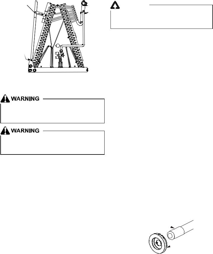
Screw
Screw
DRIP SHIELD REMOVAL
Figure 9
8 Refrigerant Lines
This product is factory-shipped with R410A and dry nitrogen mixture gas under pressure. Use appropriate service tools and follow these instructions to prevent injury.
A quenching cloth is strongly recommended to prevent scorching or marring of the equipment finish when brazing close to the painted surfaces. Use brazing alloy of 5% minimum silver content.
NOTE: Refrigerant tubing must be routed to allow adequate access for servicing and maintenance of the unit.
Do not install the air handler in a location that violates the instructions provided with the condenser. If the unit is located in an unconditioned area with high ambient temperature and/ or high humidity, the air handler may be subject to nuisance sweating of the casing. On these installations, a wrap of 2" fiberglass insulation with a vapor barrier is recommended.
8.1 Tubing Size
For the correct tubing size, follow the specification for the condenser/heat pump.
8.2 Tubing Preparation
All cut ends are to be round, burr free, and clean. Failure to follow this practice increases the chances for refrigerant leaks. The suction line is spun closed and requires tubing cutters to remove the closed end.
NOTE: To prevent possible damage to the tubing joints, do not handle coil assembly with manifold or flowrator tubes. Always use clean gloves when handling coil assemblies.
7
 CAUTION
Applying too much heat to any tube can melt the tube. Torch heat required to braze tubes of various sizes must be proportional to the size of the tube. Service personnel must use the appropriate heat level for the size of the tube being brazed.
8.3 Special Instructions
Units without a factory installed TXV come equipped with a flowrator piston for refrigerant expansion. For most installations with matching applications, no change to the flowrator piston is required. However, in mix-matched applications, a flowrator piston change may be required. See the Goodman® piston kit chart (provided in the literature packet) or consult your local distributor for details regarding mix-matched flowrator piston sizing. If the mix-match application requires a different flowrator piston size, change the flowrator piston in the flowrator body on the indoor coil before installing the coil and use the procedure in section 8.4.
NOTE: The use of a heat shield is strongly recommended when brazing to avoid burning the serial plate or the finish of the unit. Heat trap or wet rags must be used to protect heat sensitive components such as service valves and TXV valves sensing bulb.
8.4Tubing Connections for Flowrator Model
1.Loosen the 13/16 nut 1 TURN ONLY to allow high pressure tracer gas to escape. No gas indicates a possible leak.
2.After the gas has been expelled, remove the nut and discard the black or brass cap plastic seal.
3.Remove the flowrator piston to verify it is the correct size for the outdoor unit being installed and then replace the piston (changing size, if needed). See piston kit chart in the literature kit for appropriate piston size.
4.Remove the spin closure on the suction line using a tube cutter and deburr the tube.
5.Insert the suction line into the connection, slide the insulation and the rubber grommet at least 18" away from the braze joint.
SUCTION LINE
WITH SPIN CLOSURE 
RUBBER
 GROMMET
SUCTION SPUN END AND GROMMET
Figure 10
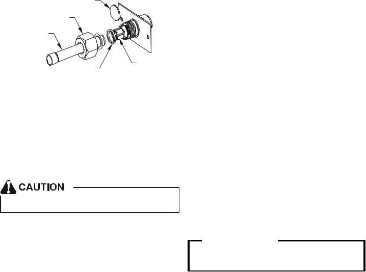
6.Remove the tailpiece clamped to the exterior of the cabinet or in the literature kit packet and slide the 13/16 nut into place.
PLASTIC or BRASS CAP
13/16” NUT
TAILPIECE
WHITE |
PISTON |
|
|
TEFLON SEAL |
|
TAILPIECE JOINT
Figure 11
7.Braze tailpiece to the line set liquid tube and braze suction line connection. Quench all brazed joints with a damp rag upon completion of brazing. Do not allow water to enter the inside of the tubing.
8.AFTER THE TAILPIECE HAS COOLED, confirm position of the white Teflon® seal and hand tighten the 13/16 nut.
9.Torque the 13/16 nut to 7-25 ft-lbs. or tighten 1/6 turn.
Excessive torque can cause orifices to stick. Use the proper torque settings when tightening orifices.
8.5 Tubing Connections for TXV Models
TXV models come with factory installed TXV with the bulb pre-installed on the vapor tube.
1.Remove refrigerant tubing panel or coil (lower) access panel.
2.Remove access valve fitting cap and depress the valve stem in access fitting to release pressure. No pressure indicates possible leak.
3.Replace the refrigerant tubing panel.
4.Remove the spin closure on both the liquid and suction tubes using a tubing cutter.
5.Insert liquid line set into liquid tube expansion and slide grommet about 18" away from braze joint.
6.Insert suction line set into suction tube expansion and slide insulation and grommet about 18" away from braze joint.
7.Braze joints. Quench all brazed joints with water or a wet rag upon completion of brazing.
9 Condensate Drain Lines
The coil drain pan has a primary and a secondary drain with 3/4" NPT female connections. The connectors required are 3/4" NPT male, either PVC or metal pipe, and should be hand tightened to a torque of no more than 37 in-lbs. to prevent damage to the drain pan connection. An insertion depth of approximately 3/8” to 1/2” (3-5 turns) should be expected at this torque.
1.Ensure drain pan hole is not obstructed.
2.To prevent potential sweating and dripping on to finished space, it may be necessary to insulate the condensate drain line located inside the building. Use Armaflex® or similar material.
A secondary condensate drain connection has been provided for areas where the building codes require it. Pitch all drain lines a minimum of 1/4" per foot to provide free drainage. Provide required support to the drain line to prevent bowing. If the secondary drain line is required, run the line separately from the primary drain and end it where condensate discharge can be easily seen.
NOTE: Water coming from secondary line means the coil primary drain is plugged and needs immediate attention.
Insulate drain lines located inside the building or above a finished living space to prevent sweating. Install a condensate trap to ensure proper drainage.
NOTE: When units are installed above ceilings, or in other locations where damage from condensate overflow may occur, it is MANDATORY to install a field fabricated auxiliary drain pan under the coil cabinet enclosure.
 CAUTION
If secondary drain is not installed, the secondary access must be plugged.
The installation must include a “P” style trap that is located as close as is practical to the evaporator coil. See Figure 12 for details of a typical condensate line “P” trap.
NOTE: Trapped lines are required by many local codes. In the absence of any prevailing local codes, please refer to the requirements listed in the Uniform Mechanical Building Code.
A drain trap in a draw-through application prevents air from being drawn back through the drain line during fan operation thus preventing condensate from draining, and if connected to a sewer line to prevent sewer gases from being drawn into the airstream during blower operation.
Field experience has shown condensate drain traps with an open vertical Tee between the air handler and the condensate drain trap can improve condensate drainage in some applications, but may cause excessive air discharge out of the open Tee. Goodman® does not prohibit this type of drain but we also do not recommend it due to the resulting air leakage. Regardless of the condensate drain design used, it is the installer’s responsibility to ensure the condensate drain system is of sufficient design to ensure proper condensate removal from the coil drain pan.
8
 Loading...