


Service Instructions
Goodman® & Amana® Brand
33 3/8" 80% Modified Two Stage Gas Furnaces
AMH8, GMH8, GDH8, ADSH8
& Accessories
This manual is to be used by qualified, professionally trained HVAC technicians only. Goodman does not assume any responsibility for property damage or personal injury due to improper service procedures or services performed by an unqualified
person.The material in this manual does not supercede manufacturer’s installation and operation instructions.
®® |
is a registered trademark of Maytag Corporation or its related companies and is used under license. |
|
|
|
All rights reserved. |
|
Copyright © 2006-2013 Goodman Manufacturing Company, L.P. |
RS6612007r1
October 2013
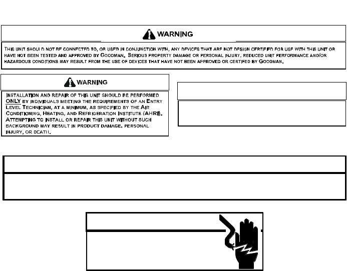
TABLE OF CONTENTS
IMPORTANT INFORMATION .......................... |
2 - 3 |
|
PRODUCT IDENTIFICATION ........................ |
4 |
- 10 |
ACCESSORIES ........................................... |
11 |
- 15 |
OPERATING INSTRUCTIONS .................... |
16 |
- 18 |
PRODUCT DESIGN ................................... |
19 - 38 |
|
SYSTEM OPERATION....................................... |
39 |
TROUBLESHOOTING ................................ |
40 - 41 |
MAINTENANCE........................................... |
42 - 45 |
SERVICING ................................................. |
46 - 62 |
SERVICING TABLE OF CONTENTS ................. |
48 |
IMPORTANT INFORMATION
Pride and workmanship go into every product to provide our customers with quality products. It is possible, however, that during its lifetime a product may require service. Products should be serviced only by a qualified service technician who is familiar with the safety procedures required in the repair and who is equipped with the proper tools, parts, testing instruments and the appropriate service manual. REVIEW ALL SERVICE INFORMATION IN THE
APPROPRIATE SERVICE MANUAL BEFORE BEGINNING REPAIRS.
IMPORTANT NOTICES FOR CONSUMERS AND SERVICERS
 RECOGNIZE SAFETY SYMBOLS, WORDS AND LABELS
 WARNING
TO PREVENT THE RISK OF PROPERTY DAMAGE, PERSONAL INJURY, OR DEATH,
DO NOT STORE COMBUSTIBLE MATERIALS OR USE GASOLINE OR OTHER
FLAMMABLE LIQUIDS OR VAPORS IN THE VICINITY OF THIS APPLIANCE.
 WARNING
GOODMAN WILL NOT BE RESPONSIBLE FOR ANY INJURY OR PROPERTY DAMAGE ARISING FROM IMPROPER SERVICE OR SERVICE PROCEDURES. IF YOU INSTALL OR PERFORM SERVICE ON THIS UNIT, YOU ASSUME RESPONSIBILITY FOR ANY PERSONAL INJURY OR PROPERTY DAMAGE WHICH MAY RESULT. MANY JURISDICTIONS REQUIRE A LICENSE TO INSTALL OR SERVICE HEATING AND AIR CONDITIONING EQUIPMENT.
 WARNING
HIGH VOLTAGE
DISCONNECT ALL POWER BEFORE SERVICING OR
INSTALLING THIS UNIT. MULTIPLE POWER SOURCES MAY
BE PRESENT. FAILURE TO DO SO MAY CAUSE PROPERTY
DAMAGE, PERSONAL INJURY OR DEATH.
2
IMPORTANT INFORMATION
Special Warning for Installation of Furnace or Air Handling Units in
Enclosed Areas such as Garages, Utility Rooms or Parking Areas
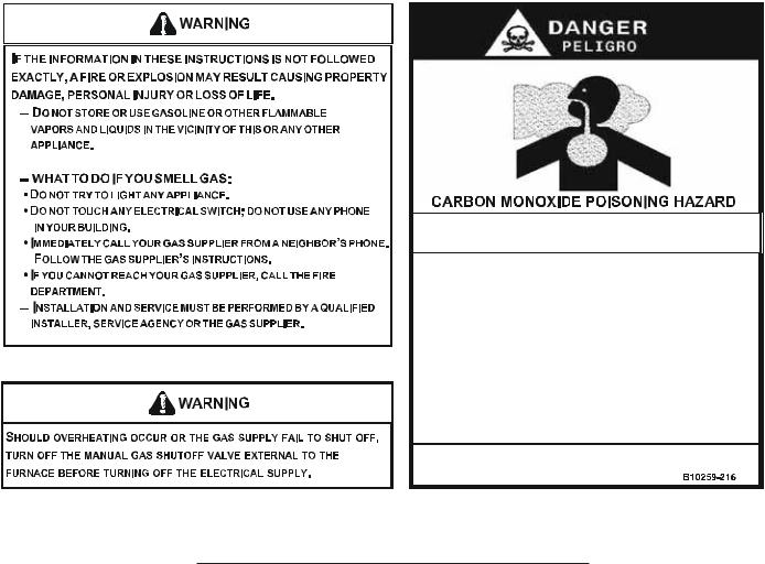
Carbon monoxide producing devices (such as an automobile, space heater, gas water heater, etc.) should not be operated in enclosed areas such as unventilated garages, utility rooms or parking areas because of the danger of carbon monoxide (CO) poisoning resulting from the exhaust emissions. If a furnace or air handler is installed in an enclosed area such as a garage, utility room or parking area and a carbon monoxide producing device is operated therein, there must be adequate, direct outside ventilation.
This ventilation is necessary to avoid the danger of CO poisoning which can occur if a carbon monoxide producing device continues to operate in the enclosed area. Carbon monoxide emissions can be (re)circulated throughout the structure if the furnace or air handler is operating in any mode.
CO can cause serious illness including permanent brain damage or death.
To locate an authorized servicer, please consult your telephone book or the dealer from whom you purchased this product. For further assistance, please contact:
CONSUMER INFORMATION LINE |
CONSUMER INFORMATION LINE |
GOODMAN® BRAND PRODUCTS |
AMANA® BRAND PRODUCTS |
TOLL FREE |
TOLL FREE |
1-877-254-4729 (U.S. only) |
1-877-254-4729 (U.S. only) |
email us at: |
email us at: hac.consumer.affairs@amanahvac.com |
customerservice@goodmanmfg.com |
fax us at: (731) 856-1821 |
fax us at: (731) 856-1821 |
(Not a technical assistance line for dealers.) |
(Not a technical assistance line for dealers.) |
|
Outside the U.S., call 1-713-861-2500.
(Not a technical assistance line for dealers.) Your telephone company will bill you for the call.
3

PRODUCT IDENTIFICATION
The model and manufacturing number are used for positive identification of component parts used in manufacturing. Please use these numbers when requesting service or parts information.
Goodman Furnace Nomenclature (13 Digits) |
|
|
|
|
||||||||
G |
M |
H |
8 0 |
0 6 0 |
3 |
A |
N |
A |
A |
|||
1 |
2 |
3 |
4 |
5 |
6 |
7 |
8 |
9 |
10 |
11 |
12 |
13 |
Brand |
|
|
|
|
|
|
|
|
|
|
|
Minor Revision |
G - Goodman |
|
|
|
|
|
|
|
|
|
|
|
A - Initial Release |
A- Amana |
|
|
|
|
|
|
|
|
|
|
|
B - 1st Revision |
Configuration |
|
|
|
|
|
|
|
|
|
|
|
|
M - Upflow/Horizontal |
|
|
|
|
|
|
|
|
|
|
|
Major Revision |
C - Downflow/Horizontal |
|
|
|
|
|
|
|
|
|
|
|
A - Initial Release |
K - Dedicated Upflow |
|
|
|
|
|
|
|
|
|
|
|
B - 1st Revision |
D - Dedicated Downflow |
|
|
|
|
|
|
|
|
|
|
|
|
|
|
|
|
|
|
|
|
|
|
|
|
Nox |
Gas Vale / Motor |
|
|
|
|
|
|
|
|
|
|
|
N - Natural Gas |
E- Convertible 2 Stage / High Efficiency |
|
|
|
|
|
|
|
|
|
|
|
X - Low NOx |
H - Convertible 2 Stage / Single Speed |
|
|
|
|
|
|
|
|
|
|
|
|
S - Single Stage / Single Speed |
|
|
|
|
|
|
|
|
|
|
|
Cabinet Width |
|
|
|
|
|
|
|
|
|
|
|
|
A - 14" |
AFUE |
|
|
|
|
|
|
|
|
|
|
|
B - 17.5" |
97 - 97% AFUE |
|
|
|
|
|
|
|
|
|
|
|
C - 21" |
80 - 80% AFUE |
|
|
|
|
|
|
|
|
|
|
|
D - 24.5" |
MBTU/h |
|
|
|
|
|
|
|
|
|
|
|
Maximum CFM |
40 - 40,000 |
|
|
|
|
|
|
|
|
|
|
|
3 - 1200 CFM |
60 - 60,000 |
|
|
|
|
|
|
|
|
|
|
|
4 - 1600 CFM |
80 - 80,000 |
|
|
|
|
|
|
|
|
|
|
|
5 - 2000 CFM |
100 - 100,000 |
|
|
|
|
|
|
|
|
|
|
|
|
120 - 120,000 |
|
|
|
|
|
|
|
|
|
|
|
|
140 - 140,000 |
|
|
|
|
|
|
|
|
|
|
|
|
Amana Furnace Nomenclature (14 Digits)
A |
D |
S |
H |
8 |
0 |
0 |
6 |
0 |
3 |
B |
N |
A |
A |
1 |
2 |
3 |
4 |
5 |
6 |
7 |
8 |
9 |
10 |
11 |
12 |
13 |
14 |
Brand |
|
|
|
|
|
|
|
|
|
|
|
|
Minor Revision |
A- Amana |
|
|
|
|
|
|
|
|
|
|
|
|
A - Initial Release |
|
|
|
|
|
|
|
|
|
|
|
|
|
B - 1st Revision |
Configuration |
|
|
|
|
|
|
|
|
|
|
|
|
|
M - Upflow/Horizontal |
|
|
|
|
|
|
|
|
|
|
|
|
Major Revision |
C - Downflow/Horizontal |
|
|
|
|
|
|
|
|
|
|
|
|
A - Initial Release |
K - Dedicated Upflow |
|
|
|
|
|
|
|
|
|
|
|
|
B - 1st Revision |
D - Dedicated Downflow |
|
|
|
|
|
|
|
|
|
|
|
|
|
|
|
|
|
|
|
|
|
|
|
|
|
|
Nox |
Motor |
|
|
|
|
|
|
|
|
|
|
|
|
N - Natural Gas |
V - Variable Speed/ComfortNet |
|
|
|
|
|
|
|
|
|
|
|
|
X - Low NOx |
E - High Efficiency |
|
|
|
|
|
|
|
|
|
|
|
|
|
S - Single Speed |
|
|
|
|
|
|
|
|
|
|
|
|
Cabinet Width |
|
|
|
|
|
|
|
|
|
|
|
|
|
A - 14" |
Gas Valve |
|
|
|
|
|
|
|
|
|
|
|
|
B - 17.5" |
M - Modulating |
|
|
|
|
|
|
|
|
|
|
|
|
C - 21" |
C - 2 Stage |
|
|
|
|
|
|
|
|
|
|
|
|
D - 24.5" |
H - Convertible 2 Stage |
|
|
|
|
|
|
|
|
|
|
|
|
|
S - Single Stage |
|
|
|
|
|
|
|
|
|
|
|
|
Maximum CFM |
|
|
|
|
|
|
|
|
|
|
|
|
|
3 - 1200 CFM |
AFUE |
|
|
|
|
|
|
|
|
|
|
|
|
4 - 1600 CFM |
97 - 97% AFUE |
|
|
|
|
|
|
|
|
|
|
|
|
5 - 2000 CFM |
80 - 80% AFUE |
|
|
|
|
|
|
|
|
|
|
|
|
|
MBTU/h
40 - 40,000
60 - 60,000
80 - 80,000
100 - 100,000
120 - 120,000
140 - 140,000
4
PRODUCT IDENTIFICATION
MODEL# |
MFG.# |
DESCRIPTION |
|
|
GDH80453A* |
Goodman® Brand 80% Modified Two-Stage Gas Furnace, Dedicated down flow installation, 33 |
|
GDH8**CA |
GDH80703A* |
3/8" tall, Induced draft, Two stage gas Valve, Integrated circuit board controlling 2nd stage gas |
|
GDH80904B* |
valve by time. Left or right side gas entry. Aluminized steel heat exchanger. PSC blower motor. |
||
|
|||
|
GDH81155C* |
115 volt silicon nitride igniter. "X" models are low NOx. Chassis sizes are 14", 17.5" and 21" wide. |
|
|
|
|
|
|
GDH80453A* |
Goodman® Brand 80% Modified Two-Stage Gas Furnace, Dedicated down flow installation, 33 |
|
|
3/8" tall, Induced draft, Two stage gas Valve, Integrated circuit board controlling 2nd stage gas |
||
|
GDH80703A* |
||
GDH8***CB |
valve by time. Left or right side gas entry. Aluminized steel heat exchanger. PSC blower motor. |
||
GDH80904B* |
|||
|
115 volt silicon nitride igniter. "X" models are low NOx. Chassis sizes are 14", 17.5" and 21" wide. |
||
|
GDH81155C* |
||
|
"CB" revisions went to a Honeywell gas valve. |
||
|
|
||
|
GDH80403A* |
Goodman® Brand 80% Modified Two-Stage Gas Furnace, New model nomenclature, fired at |
|
|
23,000 BTUH per burner. Dedicated down flow installation, 33 3/8" tall, Induced draft, Two stage |
||
|
GDH80603A* |
||
GDH8***AA |
gas Valve, Integrated circuit board controlling 2nd stage gas valve by time. Left or right side gas |
||
GDH80804B* |
|||
|
entry. Alulinized steel heat exchanger. PSC blower motor. 115 volt silicon nitride igniter. "X" |
||
|
GDH81005C* |
||
|
models are low NOx. Chassis sizes are 14", 17.5" and 21" wide. |
||
|
|
||
|
|
Goodman® Brand 80% Modified Two-Stage Gas Furnace, fired at 20,000 BTUH per burner . |
|
|
GDH80403A* |
Dedicated down flow installation, 33 3/8" tall, Induced draft, Two stage gas Valve, Integrated |
|
GDH8***BA |
GDH80603A* |
circuit board controlling 2nd stage gas valve by time. Left or right side gas entry. Aluminized steel |
|
GDH80804B* |
heat exchanger. PSC blower motor. 115 volt silicon nitride igniter. "X" models are low NOx. |
||
|
|||
|
GDH81005C* |
Chassis sizes are 14", 17.5" and 21" wide. "BA" revisions have a standard rated altitude of 4,500 |
|
|
|
ft |
|
|
|
|
|
|
|
Goodman® Brand 80% Modified Two-Stage Gas Furnace, fired at 20,000 BTUH per burner . |
|
|
GDH80403A* |
Dedicated down flow installation, 33 3/8" tall, Induced draft, Two stage gas Valve, Integrated |
|
GDH8***BB |
GDH80603A* |
circuit board controlling 2nd stage gas valve by time. Left or right side gas entry. Aluminized steel |
|
GDH80804B* |
heat exchanger. PSC blower motor. 115 volt silicon nitride igniter. "X" models are low NOx. |
||
|
|||
|
GDH81005C* |
Chassis sizes are 14", 17.5" and 21" wide. "BB" revisions have a standard rated altitude of 5,500 |
|
|
|
ft |
|
|
|
|
5
PRODUCT IDENTIFICATION
MODEL # |
MFG.# |
DESCRIPTION |
|
|
|
|
|
|
GMH80453A* |
|
|
|
GMH80703A* |
Goodman® Brand 80% Modified Two-Stage Gas Furnace, Upflow/Horizontal Left and Right |
|
|
GMH80704B* |
||
|
installation, 33 3/8" tall, Induced draft, Two stage gas Valve, Integrated circuit board |
||
|
GMH80903B* |
||
GMH8**CA |
controlling 2nd stage gas valve by time. Left or right side gas entry. Aluminized steel heat |
||
GMH80904C* |
|||
|
exchanger. PSC blower motor. 115 volt silicon nitride igniter. "X" models are low NOx. |
||
|
GMH80905C* |
||
|
Chassis sizes are 14", 17.5" 21, and 24.5" wide. |
||
|
GMH81155C* |
||
|
|
||
|
GMH81405D* |
|
|
|
GMH80453A* |
Goodman® Brand 80% Modified Two-Stage Gas Furnace, Upflow/Horizontal Left and Right |
|
|
GMH80703A* |
||
|
GMH80704B* |
installation, 33 3/8" tall, Induced draft, Two stage gas Valve, Integrated circuit board |
|
GMH8***CB |
GMH80903B* |
controlling 2nd stage gas valve by time. Left or right side gas entry. Aluminized steel heat |
|
GMH80904C* |
exchanger. PSC blower motor. 115 volt silicon nitride igniter. "X" models are low NOx. |
||
|
|||
|
GMH80905C* |
Chassis sizes are 14", 17.5" 21, and 24.5" wide. CB revision changed to a rotatable inducer |
|
|
GMH81155C* |
(clockwise) |
|
|
GMH81405D* |
|
|
|
GMH80453A* |
Goodman® Brand 80% Modified Two-Stage Gas Furnace, Upflow/Horizontal Left and Right |
|
|
GMH80703A* |
||
|
GMH80704B* |
installation, 33 3/8" tall, Induced draft, Two stage gas Valve, Integrated circuit board |
|
GMH8***CC |
GMH80903B* |
controlling 2nd stage gas valve by time. Left or right side gas entry. Aluminized steel heat |
|
GMH80904C* |
exchanger. PSC blower motor. 115 volt silicon nitride igniter. "X" models are low NOx. |
||
|
|||
|
GMH80905C* |
Chassis sizes are 14", 17.5" 21, and 24.5" wide. CC revision changed to a Honeywell gas |
|
|
GMH81155C* |
valve |
|
|
GMH81405D* |
|
|
|
|
Goodman®Brand 80%Modified Two-Stage Gas Furnace. Upflow/Horizontal Left and right |
|
|
|
installation, 33 3/8" tall, Induced draft, Two stage gas Valve, Integrated circuit board |
|
GMH8***CD |
GMH81405D* |
controlling 2nd stage gas valve by time. Left or right side gas entry. Aluminized steel heat |
|
|
|
exchanger. PSC blower motor. 115 volt silicon nitride igniter. Chassis size 24.5" wide. "CD" |
|
|
|
revision has a standard rated altittude of 5,500 ft. |
|
|
|
|
|
|
GMH80403A* |
Goodman® Brand 80% Modified Two-Stage Gas Furnace, New model nomenclature, fired |
|
|
GMH80603A* |
||
|
GMH80604B* |
at 23,000 BTUH per burner. Upflow/Horizontal Left and Right installation, 33 3/8" tall, |
|
GMH8***AA |
GMH80803B* |
Induced draft, Two stage gas Valve, Integrated circuit board controlling 2nd stage gas valve |
|
GMH80804C* |
by time. Left or right side gas entry. Alulinized steel heat exchanger. PSC blower motor. 115 |
||
|
|||
|
GMH80805C* |
volt silicon nitride igniter. "X" models are low NOx. Chassis sizes are 14", 17.5" 21, and |
|
|
GMH81005C* |
24.5" wide. |
|
|
GMH81205D* |
|
|
|
GMH80403A* |
Goodman® Brand 80% Modified Two-Stage Gas Furnace, fired at 20,000 BTUH per |
|
|
GMH80603A* |
||
|
GMH80604B* |
burner. Upflow/Horizontal Left and Right installation, 33 3/8" tall, Induced draft, Two stage |
|
GMH8***BA |
GMH80803B* |
gas Valve, Integrated circuit board controlling 2nd stage gas valve by time. Left or right side |
|
GMH80804C* |
gas entry. Aluminized steel heat exchanger. PSC blower motor. 115 volt silicon nitride |
||
|
|||
|
GMH80805C* |
igniter. "X" models are low NOx. Chassis sizes are 14", 17.5" 21, and 24.5" wide. "BA" |
|
|
GMH81005C* |
revisions have a standard rated altitude of 4,500 ft |
|
|
GMH81205D* |
|
|
|
GMH80403A* |
Goodman® Brand 80% Modified Two-Stage Gas Furnace, fired at 20,000 BTUH per |
|
|
GMH80603A* |
burner. Upflow/Horizontal Left and Right installation, 33 3/8" tall, Induced draft, Two stage |
|
|
GMH80604B* |
||
|
gas Valve, Integrated circuit board controlling 2nd stage gas valve by time. Left or right side |
||
GMH8***BB |
GMH80803B* |
||
gas entry. Aluminized steel heat exchanger. PSC blower motor. 115 volt silicon nitride |
|||
|
GMH80804C* |
||
|
igniter. "X" models are low NOx. Chassis sizes are 14", 17.5" 21, and 24.5" wide. "BB" |
||
|
GMH80805C* |
||
|
revisions and GMH81205D*BA have a standard rated altitude of 5,500 ft |
||
|
GMH81005C* |
||
|
|
||
|
|
|
6
PRODUCT IDENTIFICATION
MODEL# |
MFG.# |
DESCRIPTION |
|
|
|
|
|
|
AMH80453A* |
|
|
|
AMH80703A* |
Amana® Brand 80% Modified Two-Stage Gas Furnace, Upflow/Horizontal Left and Right |
|
|
AMH80704B* |
||
|
installation, 33 3/8" tall, Two tone painted cabinet. Induced draft, Two stage gas Valve, |
||
|
AMH80903B* |
||
AMH8**CA |
Integrated circuit board controlling 2nd stage gas valve by time. Left or right side gas entry. |
||
AMH80904C* |
|||
|
Stainless steel heat exchanger. PSC blower motor. 115 volt silicon nitride igniter. "X" |
||
|
AMH80905C* |
||
|
models are low NOx. Chassis sizes are 14", 17.5" 21, and 24.5" wide. |
||
|
AMH81155C* |
||
|
|
||
|
AMH81405D* |
|
|
|
AMH80453A* |
Amana® Brand 80% Modified Two-Stage Gas Furnace, Upflow/Horizontal Left and Right |
|
|
AMH80703A* |
||
|
AMH80704B* |
installation, 33 3/8" tall, Two tone painted cabinet. Induced draft, Two stage gas Valve, |
|
AMH8***CB |
AMH80903B* |
Integrated circuit board controlling 2nd stage gas valve by time. Left or right side gas entry. |
|
AMH80904C* |
Stainless steel heat exchanger. PSC blower motor. 115 volt silicon nitride igniter. "X" |
||
|
|||
|
AMH80905C* |
models are low NOx. Chassis sizes are 14", 17.5" 21, and 24.5" wide. CB revision changed |
|
|
AMH81155C* |
to a rotatable inducer (clockwise) |
|
|
AMH81405D* |
|
|
|
AMH80453A* |
Amana® Brand 80% Modified Two-Stage Gas Furnace, Upflow/Horizontal Left and Right |
|
|
AMH80703A* |
||
|
AMH80704B* |
installation, 33 3/8" tall, Two tone painted cabinet. Induced draft, Two stage gas Valve, |
|
AMH8***CC |
AMH80903B* |
Integrated circuit board controlling 2nd stage gas valve by time. Left or right side gas entry. |
|
AMH80904C* |
Stainless steel heat exchanger. PSC blower motor. 115 volt silicon nitride igniter. "X" |
||
|
|||
|
AMH80905C* |
models are low NOx. Chassis sizes are 14", 17.5" 21, and 24.5" wide. CC revision |
|
|
AMH81155C* |
changed to a Honeywell gas valve |
|
|
AMH81405D* |
|
|
|
|
Amana® Brand 80% Modified Two-Stage Gas Furnace, Upflow/Horizontal Left and Right |
|
|
|
installation, 33 3/8" tall, Two tone painted cabinet. Induced draft, Two stage gas Valve, |
|
AMH8**CE |
AMH81405D* |
Integrated circuit board controlling 2nd stage gas valve by time. Left or right side gas entry. |
|
Stainless steel heat exchanger. PSC blower motor. 115 volt silicon nitride igniter. "X" model |
|||
|
|
||
|
|
is low NOx. Chassis size is 24.5" wide. "CE" revision has a standard rated altitude of 5,500 |
|
|
|
ft. |
|
|
|
|
|
|
AMH80403A* |
Amana® Brand 80% Modified Two-Stage Gas Furnace, New model nomenclature, fired at |
|
|
AMH80603A* |
||
|
AMH80604B* |
23,000 BTUH per burner. Upflow/Horizontal Left and Right installation, 33 3/8" tall, Two tone |
|
AMH8***AA |
AMH80803B* |
painted cabinet. Induced draft, Two stage gas Valve, Integrated circuit board controlling 2nd |
|
AMH80804C* |
stage gas valve by time. Left or right side gas entry. Stainless steel heat exchanger. PSC |
||
|
|||
|
AMH80805C* |
blower motor. 115 volt silicon nitride igniter. "X" models are low NOx. Chassis sizes are |
|
|
AMH81005C* |
14", 17.5" 21, and 24.5" wide. |
|
|
AMH81205D* |
|
|
|
AMH80403A* |
Amana® Brand 80% Modified Two-Stage Gas Furnace, fired at 20,000 BTUH per burner. |
|
|
AMH80603A* |
||
|
AMH80604B* |
Upflow/Horizontal Left and Right installation, 33 3/8" tall, Two tone painted cabinet. Induced |
|
AMH8***BA |
AMH80803B* |
draft, Two stage gas Valve, Integrated circuit board controlling 2nd stage gas valve by time. |
|
AMH80804C* |
Left or right side gas entry. Stainless steel heat exchanger. PSC blower motor. 115 volt |
||
|
|||
|
AMH80805C* |
silicon nitride igniter. "X" models are low NOx. Chassis sizes are 14", 17.5" 21, and 24.5" |
|
|
AMH81005C* |
wide. "BA" revisions have a standard rated altitude of 4,500 ft |
|
|
AMH81205D* |
|
|
|
AMH80403A* |
Amana® Brand 80% Modified Two-Stage Gas Furnace, fired at 20,000 BTUH per burner. |
|
|
AMH80603A* |
Upflow/Horizontal Left and Right installation, 33 3/8" tall, Two tone painted cabinet. Induced |
|
|
AMH80604B* |
||
|
draft, Two stage gas Valve, Integrated circuit board controlling 2nd stage gas valve by time. |
||
AMH8***BB |
AMH80803B* |
||
Left or right side gas entry. Stainless steel heat exchanger. PSC blower motor. 115 volt |
|||
|
AMH80804C* |
||
|
silicon nitride igniter. "X" models are low NOx. Chassis sizes are 14", 17.5" 21, and 24.5" |
||
|
AMH80805C* |
||
|
wide. "BB" revisions and AMH81205D*BA have a standard rated altitude of 5,500 ft |
||
|
AMH81005C* |
||
|
|
||
|
|
|
7
PRODUCT IDENTIFICATION
MODEL# |
MFG.# |
DESCRIPTION |
|
|
ADSH800403AX* |
Amana® Brand 80% Modified Two-Stage Gas Furnace, Dedicated down flow installation, 33 |
|
|
3/8" tall, Two tone painted cabinet. Induced draft, Two stage gas Valve, Integrated circuit board |
||
|
ADSH800603AX* |
||
ADSH80***AA |
controlling 2nd stage gas valve by time. Left or right side gas entry. Stainless steel heat |
||
ADSH800804CX* |
|||
|
exchanger. PSC blower motor. 115 volt silicon nitride igniter. "X" models are low NOx. Chassis |
||
|
ADSH801005CX* |
||
|
sizes are 14", 17.5" and 21" wide. Standard rated altitude of 5,500 ft |
||
|
|
||
|
|
|
8

PRODUCT IDENTIFICATION
MODEL # |
MFG # |
DESCRIPTION |
|
|
|
|
|
Fossil Fuel Kit. The AFE18-60A control is designed for use where the indoor coil is located |
|
|
above/downstream of a gas or fossil fuel furnace when used with a heat pump. It will operate |
AFE18-60A |
N/A |
with single and two stage heat pumps and single and two stage furnaces. The AFE18-60A |
|
|
control will turn the heat pump unit off when the furnace is turned on. An anti-short cycle feature |
|
|
initiates a 3 minute timed off delay when the compressor goes off. |
|
|
|
MODEL # |
MFG # |
DESCRIPTION |
|
|
|
External Filter Rack Kit. For use with Daikin Brand upflow furnace models. This kit is |
|
|
P1221001 |
intended to provide a location, external to the furnace casing, for installation of a |
|
EFR01 |
permanent filter. The rack is mounted over the indoor air blower compartment area of |
||
P1221002F |
|||
|
|
either side panel, and provide filter retention as well as a location for attaching return air |
|
|
|
ductwork. |
|
|
|
|
|
|
|
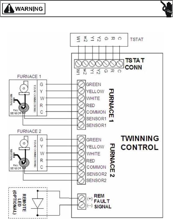
Furnace Twinning Kit. This kit allows Daikin Brand single stage 80% gas furnaces to |
|
FTK04 |
FTK04 |
operate at the same time from a single thermostat. The two furnaces to be "twinned" must |
|
be the exact same model with their circulating air blowers set to deliver the same air flow |
|||
|
|
||
|
|
at the same time. This kit cannot be used to control more than two furnaces. |
|
|
|
|
|
|
|
|
|
MODEL # |
MFG # |
DESCRIPTION |
|
|
|
High Altitude Natural Gas Kit. The kit is designed to convert 80% gas furnace models |
|
HANG20 |
N/A |
fired at 20,000 Btu's per cell for higher altitudes. This kit is required when installing these |
|
|
|
furnaces above their maximum rated altitude. |
|
|
|
|
|
|
|
High Altitude Natural Gas Kit. The kit is designed to convert 80% gas furnace models |
|
HANG21 |
N/A |
fired at 20,000 Btu's per cell for higher altitudes. This kit is required when installing these |
|
|
|
furnaces above their maximum rated altitude. |
|
|
|
|
|
|
|
High Altitude Kit. The kit is designed to convert Goodman®, Amana® Brand gas furnace |
|
|
|
models fired at 22,500 BTU's per cell for higher altitudes. This kit is required when |
|
HA02 |
N/A |
installing these furnaces above their maximum rated altitude. This kit contains # 43-49, 55- |
|
58 gas orifices. The orifices in the kit have been selected as a result of testing with the |
|||
|
|
||
|
|
American Gas Association. They will provide appropriate derating at the altitude listed in |
|
|
|
the High Altitude Charts as shown in the installation instructions of the kit. |
|
|
|
|
9

PRODUCT IDENTIFICATION
MODEL # |
MFG # |
DESCRIPTION |
|
|
|
LP Gas Low Pressure Kit. Designed for application on gas fired furnace products |
|
LPLP03 |
N/A |
installed on LP gas listed in this manual. This kit includes harness adaptors to work with |
|
White-Rodgers single & two stage gas valves,Honeywell single and two-stage gas valves, |
|||
|
|
||
|
|
as well as modulating gas valves. |
|
|
|
|
|
|
|
LP Conversion Kit. This kit converts only two-stage gas fired units from natural to propane |
|
|
|
gas. This kit supports both White-Rodgers and Honeywell two stage valves. The |
|
LPT-06 |
N/A |
conversion from natural gas (as shipped from the factory) to propane gas requires: |
|
replacing the burner orifices, replacing gas valve regulator springs (all two stage units) |
|||
|
|
||
|
|
and applying identification labels. NOx screens must be removed when converting 80% |
|
|
|
furnaces to this LP kit. |
|
|
|
|
|
|
|
Masonry Vent Kit. For use with 80% AFUE, 33" tall "H" and "S" model furnaces installed in |
|
MVK-01A |
N/A |
the upflow position only and will only be used with interior masonry chimneys. Kit |
|
MVK-02A |
incorporates a flue high limit safety switch which will interupt power to the gas valve when |
||
|
|||
|
|
a backdraft condition exists. |
|
SBT14 |
|
Downflow Subbase. For use with 80% dedicated downflow furnace models. These kits |
|
SBT17 |
|
||
N/A |
are available for the following furnace widths: 14" wide (SBT14) 17.5" wide (SBT17) and |
||
SBT21 |
|||
|
21" wide (SBT21). |
||
|
|
||
|
|
|
10
ACCESSORIES
GOODMAN® BRAND "H" Model Furnace Accessories
MODEL |
EFR01 |
AFE180-60A |
/AMUGMU |
/ASASGSAS |
SBT14 |
|
SBT17 |
SBT21 |
-LPM06 |
LPLP02LPLP03 |
FTK04 |
HA02 |
HANG20 |
HANG21 |
-MVK01 |
-MVK02 |
FSRKG14 |
FSRKG17 |
FSRKG21 |
FSRKG24 |
|
|
|
|
|
|
|
|
|
|
|
|
|
|
|
|
|
|
|
|
|
NUMBER |
|
|
|
|
|
|
|
|
|
|
|
|
|
|
|
|
|
|
|
|
|
|
|
|
|
|
|
|
|
|
|
|
|
|
|
|
|
|
|
|
|
Description |
EFR External Filter Rack |
Dual Fuel Board |
Media Air Cleaners |
Electronic Air Cleaner |
Downflow Subbase 14" |
|
Downflow Subbase 17.5" |
Downflow Subbase 21" |
Propane Gas Conversion Kit |
LP Low Pressure Shut Off Kit |
Twinning Kit |
High Altitude Orifice Kit |
High Altitude Orifices W/Pressure Switch |
High Altitude Orifices W/Pressure Switch |
Masonry Vent Kit |
Masonry Vent Kit |
Sound Reduction Kit |
Sound Reduction Kit |
Sound Reduction Kit |
Sound Reduction Kit |
GMH8 0 4 0 3 A** |
· |
· |
· |
· |
|
|
|
|
(1) |
· |
· |
(4 ) |
(2 ) |
(3 ) |
· |
|
(4 ) |
|
|
|
GMH8 0 6 0 3 A** |
· |
· |
· |
· |
|
|
|
|
(1) |
· |
· |
(4 ) |
(2 ) |
(3 ) |
· |
|
(4 ) |
|
|
|
GMH8 0 6 0 4 B** |
· |
· |
· |
· |
|
|
|
|
(1) |
· |
· |
(4 ) |
(2 ) |
(3 ) |
· |
|
|
(4 ) |
|
|
GMH8 0 8 0 3 B** |
· |
· |
· |
· |
|
|
|
|
(1) |
· |
· |
(4 ) |
(2 ) |
(3 ) |
· |
|
|
(4 ) |
|
|
GMH8 0 8 0 4 B** |
· |
· |
· |
· |
|
|
|
|
(1) |
· |
· |
(4 ) |
(2 ) |
(3 ) |
· |
|
|
(4 ) |
|
|
GMH8 0 8 0 5 C** |
· |
· |
· |
· |
|
|
|
|
(1) |
· |
· |
(4 ) |
(2 ) |
(3 ) |
· |
|
|
|
(4 ) |
|
GMH8 10 0 5 C** |
· |
· |
· |
· |
|
|
|
|
(1) |
· |
· |
(4 ) |
(2 ) |
(3 ) |
· |
|
|
|
(4 ) |
|
GMH8 12 0 5 D** |
· |
· |
· |
· |
|
|
|
|
(1) |
· |
· |
(4 ) |
|
(5 ) |
|
· |
|
|
|
(4 ) |
GMH8 14 0 5 DNC* |
· |
· |
· |
· |
|
|
|
|
(1) |
· |
· |
· |
|
(5 ) |
|
· |
|
|
|
· |
GDH8 0 4 0 3 A** |
|
· |
· |
· |
· |
|
|
|
(1) |
· |
· |
(4 ) |
(2 ) |
(3 ) |
|
|
|
|
|
|
GDH8 0 6 0 3 A** |
|
· |
· |
· |
· |
|
|
|
(1) |
· |
· |
(4 ) |
(2 ) |
(3 ) |
|
|
|
|
|
|
GDH8 0 8 0 4 B** |
|
· |
· |
· |
|
|
· |
|
(1) |
· |
· |
(4 ) |
(2 ) |
(3 ) |
|
|
|
|
|
|
GDH8 10 0 5 C** |
|
· |
· |
· |
|
|
|
· |
(1) |
· |
· |
(4 ) |
(2 ) |
(3 ) |
|
|
|
|
|
|
|
|
|
|
|
|
|
not approved for this model |
|
|
|
|
|
|
|
|
|
||||
|
|
|
|
|
|
|
|
|
|
|
|
|
|
|
|
|||||
|
|
|
|
|
· |
|
approved for this model |
|
|
|
|
|
|
|
|
|
|
|||
|
|
|
|
|
|
|
|
|
|
|
|
|
|
|
|
|
|
|
|
|
(1) W/R & HW 2 stg valve
(2) BA REV 4,500 - 10,000 FT (excluding GMH81205D*BA)
(3) BB REV 5,500 - 10,000 FT
(4) AA Rev
(5) GMH81205D*BA and GMH81405D*CD 5,500 FT - 10,000 FT
11

ACCESSORIES
AMANA® BRAND "H" Model Furnace Accessories
MODEL |
EFR01 |
AFE180-60A |
/AMUGMU |
/ASASGSAS |
SBT14 |
|
SBT17 |
SBT21 |
-LPM06 |
LPLP02LPLP03 |
FTK04 |
HA02 |
HANG20 |
HANG21 |
-MVK01 |
-MVK02 |
FSRKG14 |
FSRKG17 |
FSRKG21 |
FSRKG24 |
|
|
|
|
|
|
|
|
|
|
|
|
|
|
|
|
|
|
|
|
|
NUMBER |
|
|
|
|
|
|
|
|
|
|
|
|
|
|
|
|
|
|
|
|
|
|
|
|
|
|
|
|
|
|
|
|
|
|
|
|
|
|
|
|
|
Description |
EFR External Filter Rack |
Dual Fuel Board |
Media Air Cleaners |
Electronic Air Cleaner |
Downflow Subbase 14" |
|
Downflow Subbase 17.5" |
Downflow Subbase 21" |
Propane Gas Conversion Kit |
LP Low Pressure Shut Off Kit |
Twinning Kit |
High Altitude Orifice Kit |
High Altitude Orifices W/Pressure Switch |
High Altitude Orifices W/Pressure Switch |
Masonry Vent Kit |
Masonry Vent Kit |
Sound Reduction Kit |
Sound Reduction Kit |
Sound Reduction Kit |
Sound Reduction Kit |
AMH8 0 4 0 3 A** |
· |
· |
· |
· |
|
|
|
|
(1) |
· |
· |
(4 ) |
(2 ) |
(3 ) |
· |
|
(4 ) |
|
|
|
AMH8 0 6 0 3 A** |
· |
· |
· |
· |
|
|
|
|
(1) |
· |
· |
(4 ) |
(2 ) |
(3 ) |
· |
|
(4 ) |
|
|
|
AMH8 0 6 0 4 B** |
· |
· |
· |
· |
|
|
|
|
(1) |
· |
· |
(4 ) |
(2 ) |
(3 ) |
· |
|
|
(4 ) |
|
|
AMH8 0 8 0 3 B** |
· |
· |
· |
· |
|
|
|
|
(1) |
· |
· |
(4 ) |
(2 ) |
(3 ) |
· |
|
|
(4 ) |
|
|
AMH8 0 8 0 4 B** |
· |
· |
· |
· |
|
|
|
|
(1) |
· |
· |
(4 ) |
(2 ) |
(3 ) |
· |
|
|
(4 ) |
|
|
AMH8 0 8 0 5 C** |
· |
· |
· |
· |
|
|
|
|
(1) |
· |
· |
(4 ) |
(2 ) |
(3 ) |
· |
|
|
|
(4 ) |
|
AMH8 10 0 5 C** |
· |
· |
· |
· |
|
|
|
|
(1) |
· |
· |
(4 ) |
(2 ) |
(3 ) |
· |
|
|
|
(4 ) |
|
AMH8 12 0 5 D** |
· |
· |
· |
· |
|
|
|
|
(1) |
· |
· |
(4 ) |
|
(5 ) |
|
· |
|
|
|
(4 ) |
AMH8 14 0 5 DNC* |
· |
· |
· |
· |
|
|
|
|
(1) |
· |
· |
· |
|
(5 ) |
|
· |
|
|
|
· |
ADS H8 0 0 4 0 3 A** |
|
· |
· |
· |
· |
|
|
|
(1) |
· |
· |
|
|
· |
|
|
|
|
|
|
ADS H8 0 0 6 0 3 A** |
|
· |
· |
· |
· |
|
|
|
(1) |
· |
· |
|
|
· |
|
|
|
|
|
|
ADS H8 0 0 8 0 4 B** |
|
· |
· |
· |
|
|
· |
|
(1) |
· |
· |
|
|
· |
|
|
|
|
|
|
ADS H8 0 10 0 5 C** |
|
· |
· |
· |
|
|
|
· |
(1) |
· |
· |
|
|
· |
|
|
|
|
|
|
|
|
|
|
|
|
|
not approved for this model |
|
|
|
|
|
|
|
|
|
||||
|
|
|
|
|
|
|
|
|
|
|
|
|
|
|
|
|||||
|
|
|
|
|
· |
|
approved for this model |
|
|
|
|
|
|
|
|
|
|
|||
|
|
|
|
|
|
(1) W/R & HW 2 stg valve |
|
|
|
|
|
|
|
|
|
|
||||
(2) BA REV 4,500 - 10,000 FT (excluding AMH81205D*BA)
(3) BB REV 5,500 - 10,000 FT
(4) AA Rev
(5) AMH81205D*BA and AMH81405D*CE 5,500 FT - 10,000 FT
12
ACCESSORIES
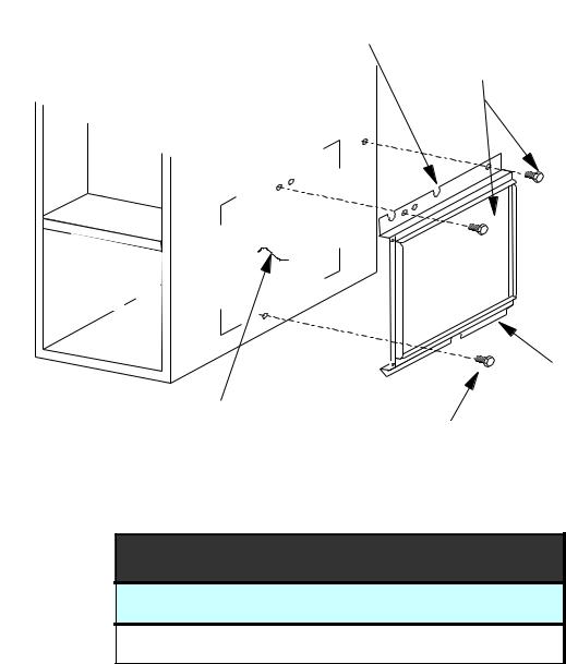
EXTERNAL FILTER RACK KIT
( EFR01 )
SLOTS IN FILTER
CLEAR SCREWS
ON UNIT
BLOWER DECK
SCREWS
UNIT SIDE
PANEL
FRONT |
|
|
|
OF UNIT |
|
|
|
|
|
FILTER RACK ASSEMBLY |
|
BASE |
|
(FACE FILTER OPENING |
|
|
TOWARDS FRONT |
||
OF UNIT |
|
||
RETURN AIR |
OF UNIT) |
||
|
|||
|
|
||
|
CUTOUT AREA |
LOWER EDGE |
|
|
|
||
|
|
SCREW |
EFR01 EXTERNAL FILTER RACK KIT
Used on Models
80% Upflow Model Furnaces
13
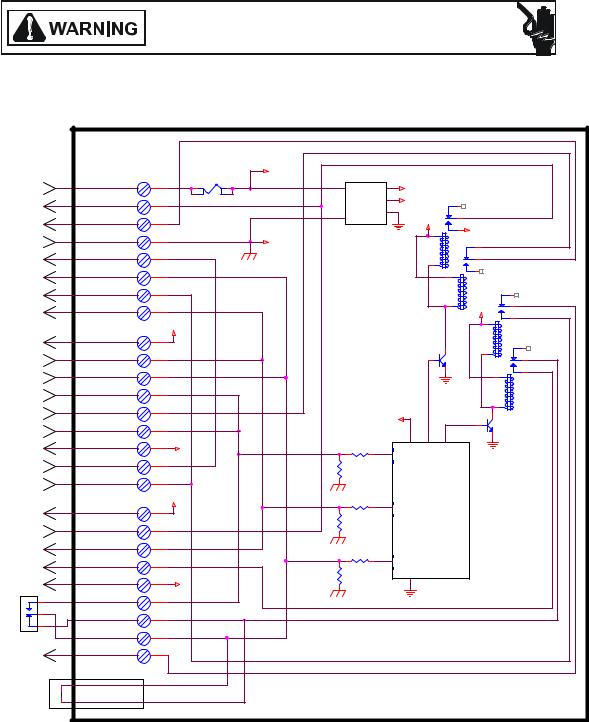
ACCESSORY WIRING DIAGRAMS
HIGH VOLTAGE!
DISCONNECT ALL POWER BEFORE SERVICING OR INSTALLING THIS
UNIT. MULTIPLE POWER SOURCES MAY BE PRESENT. FAILURE TO
DO SO MAY CAUSE PROPERTY DAMAGE, PERSONAL INJURY OR DEATH.
|
|
|
|
|
24VAC |
|
|
POWER SUPPLY |
|
|
P1-8 |
F1 |
3A |
+VDC |
|
|
R |
|
|
|
|||
INPUT |
|
|
|
POWER |
+5VDC |
|
|
FURNACE DEMAND |
|
|
P1-7 |
|
W1-FURN |
||
F |
W1 |
|
SUPPLY |
|
|||
|
|
|
|||||
OUTPUT |
|
|
|
|
W2-HP |
||
BLOWER FAN DEMAND |
U |
G |
P1-4 |
|
|
+VDC |
|
OUTPUT |
|
|
|
|
24VAC |
||
POWER SUPPLY INPUT |
R |
C |
P1-6 |
|
C |
|
G-STAT |
(COMMON) |
N |
|
|
|
K1 |
|
|
SECOND STAGE FURNACE |
|
P1-5 |
|
|
|
G-FURN |
|
DEMAND OUTPUT |
A |
W2 |
|
|
|
|
|
|
|
|
|
|
|||
COMPRESSOR OUTPUT |
C |
Y |
P1-2 |
|
|
|
|
|
|
|
|
|
|
||
SECOND STAGE |
E |
Y2 |
P1-3 |
|
|
K2 |
Y2-HP |
COMPRESSOR OUTPUT |
|
|
|
|
|
||
REVERSING VALVE |
|
O |
P1-1 |
|
|
|
+VDC |
OUTPUT |
|
|
|
|
|
Y2-STAT |
|
|
|
|
24VAC |
|
|
||
|
|
|
|
|
Y2-FURN |
||
|
|
|
|
|
|
|
|
POWER SUPPLY OUT |
|
R |
P2-2 |
|
|
|
K4 |
TO THERMOSTAT |
T |
|
|
|
Q1 |
Y-STAT |
|
CALL FOR |
O |
P2-1 |
|
|
|
Y-FURN |
|
REVERSING VALVE |
H |
|
|
|
|
Y-HP |
|
CALL FOR |
E |
Y |
P2-7 |
|
|
|
|
COMPRESSOR |
|
|
|
|
|
||
CALL FOR |
R |
E |
P2-8 |
|
|
|
K3 |
EMERGENCY HEAT |
M |
|
|
|
|
|
|
CALL FOR |
|
P2-5 |
|
|
|
Q2 |
|
BLOWER FAN |
O |
G |
|
|
+5VDC |
|
|
|
|
|
|
||||
CALL FOR |
S |
W1 |
P2-9 |
|
|
|
|
FURNACE HEAT |
|
|
|
|
|
||
POWER SUPPLY COMMON |
T |
C |
P2-3 |
C |
E/W1 |
|
|
OUT TO THERMOSTAT |
A |
|
|
|
|
|
|
CALL FOR 2ND STAGE |
|
P2-4 |
|
1.0K |
|
|
|
FURNACE HEAT |
T |
W2 |
|
|
|
|
|
|
|
|
|
|
|||
CALL FOR 2ND STAGE |
|
Y2 |
P2-6 |
|
|
|
|
COMPRESSOR |
|
|
|
|
MICROPROCESSOR |
|
|
|
|
|
24VAC |
O |
|
||
|
|
|
|
|
|||
POWER SUPPLY OUT |
|
R |
P3-9 |
|
|
|
|
TO HP CONTROL |
|
|
|
6.8K |
|
|
|
HP CALL FOR FURNACE |
H |
W2 |
P3-8 |
|
|
|
|
(DURING DEFROST) |
|
|
|
|
|
||
REVERSING |
E |
O |
P3-7 |
|
Y |
|
|
VALVE OUTPUT |
|
|
|
|
|||
COMPRESSOR |
A |
Y |
P3-2 |
|
|
|
|
CONTACTOR OUTPUT |
T |
|
|
6.8K |
|
|
|
POWER SUPPLY COMMON |
C |
P3-6 |
C |
|
|
|
|
OUT TO HP CONTROL |
P |
|
|
|
|
|
|
|
OT-NO |
P3-3 |
|
|
|
|
|
ODT (OUTDOOR |
|
|
|
|
|
||
U |
|
P3-1 |
|
|
|
|
|
THERMOSTAT) |
|
|
|
|
|
||
|
M OT-NC |
P3-4 |
|
|
|
|
|
2ND STAGE COMPRESSOR |
P |
OT-C |
P3-5 |
|
|
|
|
DEMAND OUTPUT |
|
Y2 |
|
|
|
|
|
|
|
|
|
|
|
||
|
|
|
|
|
|
|
|
|
2 |
|
|
|
|
|
|
|
BREAK FOR ODT |
|
|
|
|
|
|
|
1 |
|
|
|
|
|
|
ALL FUEL SYSTEM CONTROL BOARD - AFE18-60A
This wiring diagram is for reference only. Not all wiring is as shown above. Refer to the appropriate wiring diagram for the unit being serviced.
(For use with Heat Pumps in conjunction with 80% or 90% Single-Stage or Two-Stage Furnaces)
14
ACCESSORY WIRING DIAGRAMS
HIGH VOLTAGE!
DISCONNECT ALL POWER BEFORE SERVICING OR INSTALLING THIS
UNIT. MULTIPLE POWER SOURCES MAY BE PRESENT. FAILURE TO
DO SO MAY CAUSE PROPERTY DAMAGE, PERSONAL INJURY OR DEATH.
FURNACE TWINING KIT - FTK04 (UTEC Control Board)
This wiring diagram is for reference only. Not all wiring is as shown above. Refer to the appropriate wiring diagram for the unit being serviced.
(For use only with 80% or 90% Single-Stage Furnaces)
15

OPERATING INSTRUCTIONS
 FOR YOUR SAFETY READ BEFORE OPERATING
If you do not follow these instructions exactly, a fire or explosion may result causing property damage, personal injury or loss of life.
A. This appliance does not have a pilot. It is equipped with an ignition device which
automatically lights the burners. Do not try to light the burners by hand.
B. BEFORE OPERATING smell around the appliance area for gas. Be sure to smell next to the floor because some gas
is heavier than air and will settle on the floor.
WHAT TO DO IF YOU SMELL GAS Do not try to light any appliance.
 Do not touch any electric switch;
do not use any telephone in your building.
Immediately call your supplier
from a neighbor's phone. Follow the gas suppliers instructions.
 If you cannot reach your gas supplier, call the fire department.
C. Use only your hand to move the gas control switch or knob. Never use tools. If the gas control switch or knob will not operate, don't try to repair it,
call a qualified service technician. Force or attempted repair may result in
a fire or explosion.
D. Do not use this appliance if any part has been under water. Immediately call a qualified service technician to inspect
the appliance and to replace any part of the control system and any gas control which has been under water.
 OPERATING INSTRUCTIONS
1.STOP! Read the safety information above on this label.
2.Set the thermostat to lowest setting.
3.Turn off all electric power to the appliance.
4.This appliance is equipped with an automatic ignition system which automatically lights the burners. Do not
try to light the burners by hand.
5.Remove control access panel.
6.Move the gas control switch or knob to "OFF".
7. Wait five (5) minutes to clear out any gas. If you then smell gas, STOP! Follow "B" in the safety information above on this label. If you don't smell gas, go to the next step.
8.Move the gas control switch or knob to "ON".
9.Replace control access panel.
10.Turn on all electric power to the appliance.
11.Set the thermostat to the desired setting.
12.If the appliance will not operate, follow the instructions "To Turn Off Gas To Appliance" and call your service technician or gas supplier.
GAS CONTROL
SWITCH SHOWN
IN "ON" POSITION
 TO TURN OFF GAS TO APPLIANCE
4. Move the gas control switch or knob
to "OFF". Do not force. 5. Replace control access panel.
WARNING: Improper
alteration, service or maintenance can cause injury or property damage.
Refer to the user's information manual
provided with this
consult a qualified
or the gas supplier.
This furnace must be
instructions and local codes. In the absence of local codes, follow the National Fuel Gas
Code, ANSI Z223.1.
For indoor installation.
PGB & PGJ For outdoor
installation only.
WARNING: If not installed, operated
and maintained in accordance with the
manufacturer's instructions, this
product could expose you to substances in fuel combustion which can cause death or serious
illness and which are known to the
State of California to cause cancer, birth defects or other
reproductive harm. This product contains
fiberglass insulation.
Fiberglass insulation contains a chemical
California to cause cancer.
FOR YOUR SAFETY |
Do not store or use gasoline or |
other flammable vapors and liquids in the vicinity of this |
|
or any other appliance. |
0140F00001P |
16
OPERATING INSTRUCTIONS
CONSIGNES DE SECURITE - LIRE
AVANT D'ALLUMER L'APPAREIL
AVERTISSEMENT: Le non-respect des instructions qui suivent peut entrainer^ un risque d'incendie ou d'explosion causant des dommages, des blessures ou la mort.
A.Cet appareil comporte pas de veilleuse. Il est muni d'un mecanisme qui allume automatiquement le bruleur^ . N'allumez paz le bruleur^ manuellement.
B.Sentir tout autour de l'appariel AVANT D'ALLUMER afin de deceler toute fuite de gaz. Assurez-vous de sentir tout pres du plancher car certains gaz sont plus lourds que l'air et se deposeront sur le plancher.
SI VOUS SENTEZ UNE ODEUR DE GAZ:
Ne tentez d'allumer aucun appariel.
Ne touchez pas aux interrupteurs electriques; n'utiliser aucun telephone dans l'edifice ou vous vous trouvez.
Appelez immediatement votre fournisseur de gaz en utilisant le telephone d'un voisin et suivez les instructions du fournisseur.
Appelez les pompiers si vous ne parvenez pas a rejoindre votre fournisseur de gaz.
C. N'utiliser que votre main pour pousser ou tourner le commande du gaz. N'utilisez jamais d'outils. Si vous ne parvenez pas a pousser ou a tourner la commande, ne tentez pas de la reparer; appelez un reparateur qualifie. Forcer la commande ou essayer de la reparer peut entrainer^ un risque d'incendie ou d'explosion.
D. N'utilisez pas cet appareil si l'une de ses parties a ete dans l'eau. Si cela se produit, demandez immediatement a un reparateur qualifie d'inspecter l'appareil et de remplacer toute piece du systeme de controle^ et toute commande de gaz ayant ete dans l'eau.
0140F00002P
 INSTRUCTIONS DE SERVICE
1. UN INSTANT! Lisez d'abord les consignes de securite ci-dessus.
2. Reglez le thermostat a son point le plus bas. 3. Coupez l'alimentation electrique de l'appareil. 4. Cet appareil est muni d'un mecanisme qui
allume automatiquement le bruleur^ . Ne tentez pas d'allumer le bruleur^ manuellement.
5. Retirez le panneau d'acces de la commande.
6. Mettez la commande de gaz a la position
^
ARRET ("OFF").
7. Attendez cinq (5) minutes afin de permettre a
tout gaz present d'etre^ evacue. Si vous sentez
^
une odeur de gaz a ce moment, ARRETEZ! et suivez les consignes de securite donnees au paragraphe B ci-dessus. Si vous ne sentez pas de gaz, passez a l'etape suivante.
8.Mettez la commande de gaz a la position MARCHE ("ON").
9.Remettez la panneau d'acces de la commande en place.
10.Retablissez l'alimenation electrique de l'appareil.
11.Reglez le thermostat a le temperature desiree.
12.Si l'appareil ne fonctionne pas, suivez les instructions intitulees "Arret^ du gaz" et appelez un reparateur qualifie ou votre fournisseur de gaz.
Commande de gaz en position
"MARCHE"
^
ARRET DU GAZ
1.Reglez le thermostat a son point le plus bas.
2.Coupez l'alimentation electrique de l'appareil si vous devez effectuer un entretien.
3.Retirez le panneau d'acces de la commande. ^
4.Mettez la commande de gaz a la position ARRET ("OFF").
5.Remettez le panneau d'acces de la commande en place.
17

OPERATING INSTRUCTIONS
ROBINET A GAZ |
MANUEL, EN POS |
"ON/MARCHE" |
GAS |
INLET |
ARRIVEE |
DU GAZ |
MANUAL GAS |
LEVER SHOWN |
IN "ON" POS |
18

PRODUCT DESIGN
Safety
Please adhere to the following warnings and cautions when installing, adjusting, altering, servicing, or operating the furnace.
 WARNING
TO PREVENT PERSONAL INJURY OR DEATH DUE TO IMPROPER INSTALLATION, ADJUSTMENT, ALTERATION, SERVICE OR MAINTENANCE, REFER TO THIS MANUAL. FOR ADDITIONAL ASSISTANCE OR INFORMATION, CONSULT A QUALIFIED INSTALLER, SERVICE AGENCY OR THE GAS SUPPLIER.
 WARNING
THIS PRODUCT CONTAINS OR PRODUCES A CHEMICAL OR CHEMICALS WHICH MAY CAUSE SERIOUS ILLNESS OR DEATH AND WHICH ARE KNOWN TO THE STATE OF CALIFORNIA TO CAUSE CANCER, BIRTH DEFECTS OR OTHER REPRODUCTIVE HARM.
 WARNING
TO PREVENT POSSIBLE PROPERTY DAMAGE, PERSONAL INJURY OR DEATH DUE TO ELECTRICAL SHOCK, THE FURNACE MUST BE LOCATED TO PROTECT THE ELECTRICAL COMPONENTS FROM WATER.
Charge (ESD) Precautions
NOTE: Discharge body’s static electricity before touching unit. An electrostatic discharge can adversely affect electrical components.
Use the following precautions during furnace installation and servicing to protect the integrated control module from damage. By putting the furnace, the control, and the person at the same electrostatic potential, these steps will help avoid exposing the integrated control module to electrostatic discharge. This procedure is applicable to both installed and uninstalled (ungrounded) furnaces.
1.Disconnect all power to the furnace. Do not touch the integrated control module or any wire connected to the control prior to discharging your body’s electrostatic charge to ground.
2.Firmly touch a clean, unpainted, metal surface of the furnace near the control. Any tools held in a person’s hand during grounding will be discharged.
3.Service integrated control module or connecting wiring following the discharge process in Step 2. Use caution not to recharge your body with static electricity; (i.e., do not move or shuffle your feet, do not touch ungrounded objects, etc.). If you come in contact with an ungrounded object, repeat Step 2 before touching control or wires.
4.Discharge any static electricity from your body to ground before removing a new control from its container. Follow Steps 1 through 3 if installing the control on a furnace. Return any old or new controls to their containers before touching any ungrounded object.
Product Application
This product is designed for use as a residential home gas furnace. It is not designed or certified for use in mobile home, trailer, or recreational vehicle applications.
This furnace can be used in the following non-industrial commercial applications: Schools, Office buildings, Churches,
Retail stores, Nursing homes, Hotels/motels, Common or office areas. In such applications, the furnace must be installed with the installation instructions.
Goodman® & Amana® Brand 80% furnaces are ETL certified appliances and are appropriate for use with natural or propane gas. (NOTE: If using propane gas, a propane conversion kit is required).
IMPORTANT NOTE: The 80% furnace cannot be installed as a direct vent (i.e.., sealed combustion) furnace. The burner box is present only to help reduce sound transmission from the burners to the occupied space.
To ensure proper installation, operation and servicing, thoroughly read the installation and service manuals for specifics pertaining to the installation, servicing and application of this product.
 WARNING
POSSIBLE PROPERTY DAMAGE, PERSONAL INJURY OR DEATH DUE TO FIRE, EXPLOSION, SMOKE, SOOT, CONDENSTAION, ELECTRICAL SHOCK OR CARBON MONOXIDE MAY RESULT FROM IMPROPER INSTALLATION, REPAIR, OPERATION, OR MAINTENANCE OF THIS PRODUCT.
 WARNING
TO PREVENT PROPERTY DAMAGE, PERSONAL INJURY OR DEATH DUE TO FIRE, DO NOT INSTALL THIS FURNACE IN A MOBILE HOME, TRAILER, OR RECREATIONAL VEHICLE.
To ensure proper furnace operation, install, operate, maintain and service the furnace in accordance with the installation, operation and service instructions, all local building codes and ordinances. In their absence, follow the latest edition of the National Fuel Gas Code (NFPA 54/ANSI Z223.1), and/or CAN/CGA B149 Installation Codes, local plumbing or waste water codes, and other applicable codes.
A copy of the National Fuel Gas Code (NFPA 54/ANSI Z223.1) can be obtained from any of the following:
American National Standards Institute 1430 Broadway
New York, NY 10018
National Fire Protection Association
1 Batterymarch Park
Quincy, MA 02269
19
 Loading...