


Service Instructions
ComfortNet™
ASXC, DSXC, and GSXC Condensing Units,
ASZC, DSZC and GSZC Split System Heat Pumps
with R-410A Refrigerant
Blowers, Coils, & Accessories
This manual is to be used by qualified, professionally trained HVAC technicians only. Goodman does not assume any responsibility for property damage or personal injury due to improper service procedures or services performed by an unqualified person.
Copyright © 2015-2017 Goodman Manufacturing Company, L.P.
RS6200007r14
December 2017


 isaregisteredtrademarkofMaytagCorporationoritsrelatedcompaniesandisusedunderlicensetoGoodmanCompany,L.P.,Houston,TX. Allrightsreserved.
IMPORTANT INFORMATION
Pride and workmanship go into every product to provide our customers with quality products. It is possible, however, that during its lifetime a product may require service. Products should be serviced only by a qualified service technician who is familiar with the safety procedures required in the repair and who is equipped with the proper tools, parts, testing instruments and the appropriate service manual. REVIEW ALL SERVICE INFORMATION IN THE APPROPRIATE SERVICE MANUAL BEFORE
BEGINNINGREPAIRS.
IMPORTANT NOTICES FOR CONSUMERS AND SERVICERS
RECOGNIZE SAFETY SYMBOLS, WORDS AND LABELS
ONLY PERSONNEL THAT HAVE BEEN TRAINED TO INSTALL, ADJUST, SERVICE OR REPAIR (HEREINAFTER, “SERVICE”) THE EQUIPMENT SPECIFIED IN THIS MANUAL SHOULD SERVICE THE EQUIPMENT. THE MANUFACTURER WILL NOT BE RESPONSIBLE FOR ANY INJURY OR PROPERTY DAMAGE ARISING FROM IMPROPER SERVICE OR SERVICE PROCEDURES. IF YOU SERVICE THIS UNIT, YOU ASSUME RESPONSIBILITY FOR ANY INJURY OR PROPERTY DAMAGE WHICH MAY RESULT. IN ADDITION, IN JURISDICTIONS THAT REQUIRE ONE OR MORE LICENSES TO SERVICE THE EQUIPMENT SPECIFIED IN THIS MANUAL, ONLY LICENSED PERSONNEL SHOULD SERVICE THE EQUIPMENT. IMPROPER INSTALLATION, ADJUSTMENT, SERVICING OR REPAIR OF THE EQUIPMENT SPECIFIED IN THIS MANUAL, OR ATTEMPTING TO INSTALL, ADJUST, SERVICE OR REPAIR THE EQUIPMENT SPECIFIED IN THIS MANUAL WITHOUT PROPER TRAINING MAY RESULT IN PRODUCT DAMAGE, PROPERTY DAMAGE, PERSONAL INJURY OR DEATH.
 WARNING
TO PREVENT THE RISK OF PROPERTY DAMAGE, PERSONAL INJURY, OR DEATH, DO NOT STORE COMBUSTIBLE MATERIALS OR USE GASOLINE OR OTHER FLAMMABLE LIQUIDS OR VAPORS IN THE VICINITY OF THIS APPLIANCE.
To locate an authorized servicer, please consult your telephone book or the dealer from whom you purchased this product. For further assistance, please contact:
CONSUMER INFORMATION LINE
GOODMAN® BRAND PRODUCTS |
AMANA® BRAND PRODUCTS |
TOLL FREE |
TOLL FREE |
1-877-254-4729 (U.S. only) |
1-877-254-4729 (U.S. only) |
email us at: customerservice@goodmanmfg.com |
email us at: customerservice@goodmanmfg.com |
fax us at: (713) 856-1821 |
fax us at: (713) 856-1821 |
(Not a technical assistance line for dealers.) |
(Not a technical assistance line for dealers.) |
Outside the U.S., call 1-713-861-2500. |
|
(Not a technical assistance line for dealers.) |
Your telephone company will bill you for the call. |


 isaregisteredtrademarkofMaytagCorporationoritsrelatedcompaniesandisusedunderlicensetoGoodmanCompany,L.P.,Houston,TX. Allrightsreserved.
2
IMPORTANT INFORMATION
SAFE REFRIGERANT HANDLING
While these items will not cover every conceivable situation, they should serve as a useful guide.
 WARNING
REFRIGERANTS ARE HEAVIER THAN AIR. THEY CAN "PUSH OUT" THE OXYGEN IN YOUR LUNGS OR IN ANY ENCLOSED SPACE. TO AVOID POSSIBLE DIFFICULTY IN BREATHING OR DEATH:
•NEVER PURGE REFRIGERANT INTO AN ENCLOSED ROOM OR SPACE. BY LAW, ALL REFRIGERANTS MUST BE RECLAIMED.
•IF AN INDOOR LEAK IS SUSPECTED, THOROUGHLY VENTILATE THE AREA BEFORE BEGINNING WORK.
•LIQUID REFRIGERANT CAN BE VERY COLD. TO AVOID POSSIBLE FROSTBITE OR BLINDNESS, AVOID CONTACT WITH REFRIGERANT AND WEAR GLOVES AND GOGGLES. IF LIQUID REFRIGERANT DOES CONTACT YOUR SKIN OR EYES, SEEK MEDICAL HELP IMMEDIATELY.
•ALWAYS FOLLOW EPA REGULATIONS. NEVER BURN REFRIGERANT, AS POISONOUS GAS WILL BE PRODUCED.
 WARNING
THE UNITED STATES ENVIRONMENTAL PROTECTION AGENCY ("EPA") HAS ISSUED VARIOUS REGULATIONS REGARDING THE INTRODUCTION AND DISPOSAL OF REFRIGERANTS INTRODUCED INTO THIS UNIT. FAILURE TO FOLLOW THESE REGULATIONS MAY HARM THE ENVIRONMENT AND CAN LEAD TO THEH IMPOSITION OF SUBSTANTIAL FINES. THESE REGULATIONS MAY VARY BY JURISDICTION. SHOULD QUESTIONS ARISE, CONTACT YOUR LOCAL EPA OFFICE.
 WARNING
TO AVOID POSSIBLE EXPLOSION:
• NEVER APPLY FLAME OR STEAM TO A REFRIGERANT CYLINDER. IF YOU MUST HEAT A CYLINDER FOR FASTER CHARGING, PARTIALLY IMMERSE IT IN WARM WATER.
•NEVER FILL A CYLINDER MORE THAN 80% FULL OF LIQUID REFRIGERANT.
•NEVER ADD ANYTHING OTHER THAN R-22 TO AN R-22 CYLINDER OR R-410A TO AN R-410A CYLINDER. THE SERVICE EQUIPMENT USED MUST
BE LISTED OR CERTIFIED FOR THE TYPE OF REFRIGERANT USED.
• STORE CYLINDERS IN A COOL, DRY PLACE. NEVER USE A CYLINDER AS A PLATFORM OR A ROLLER.
 WARNING
TO AVOID POSSIBLE EXPLOSION, USE ONLY RETURNABLE (NOT DISPOSABLE) SERVICE CYLINDERS WHEN REMOVING REFRIGERANT FROM A SYSTEM.
• ENSURE THE CYLINDER IS FREE OF DAMAGE WHICH COULD LEAD TO A LEAK OR EXPLOSION.
•ENSURE THE HYDROSTATIC TEST DATE DOES NOT EXCEED 5 YEARS.
•ENSURE THE PRESSURE RATING MEETS OR EXCEEDS 400 LBS.
WHEN IN DOUBT, DO NOT USE CYLINDER.
 WARNING
TO AVOID POSSIBLE INJURY, EXPLOSION OR DEATH, PRACTICE SAFE HANDLING OF REFRIGERANTS.
 WARNING
SYSTEM CONTAMINANTS, IMPROPER SERVICE PROCEDURE AND/OR PHYSICAL ABUSE AFFECTING HERMETIC COMPRESSOR ELECTRICAL TERMINALS MAY CAUSE DANGEROUS SYSTEM VENTING.
Thesuccessfuldevelopmentofhermeticallysealedrefrigeration compressors has completely sealed the compressor's moving parts and electric motor inside a common housing, minimizing refrigerant leaks and the hazards sometimes associated with moving belts, pulleys or couplings.
Fundamental to the design of hermetic compressors is a method whereby electrical current is transmitted to the compressor motor through terminal conductors which pass through the compressor housing wall. These terminals are sealed in a dielectric material which insulates them from the housing and maintains the pressure tight integrity of the hermetic compressor. The terminals and their dielectric embedment are strongly constructed, but are vulnerable to careless compressor installation or maintenance procedures and equally vulnerable to internal electrical short circuits caused by excessive system contaminants.
In either of these instances, an electrical short between the terminal and the compressor housing may result in the loss of integrity between the terminal and its dielectric embedment. This loss may cause the terminals to be expelled, thereby venting the vaporous and liquid contents of the compressor housing and system.
A venting compressor terminal normally presents no danger to anyone, providing the terminal protective cover is properly in place.
If, however, the terminal protective cover is not properly in place, a venting terminal may discharge a combination of
(a)hot lubricating oil and refrigerant
(b)flammable mixture (if system is contaminated with air)
in a stream of spray which may be dangerous to anyone in the vicinity. Death or serious bodily injury could occur.
Under no circumstances is a hermetic compressor to be electrically energized and/or operated without having the terminal protective cover properly in place.
See Service Section S-17 for proper servicing.
3

PRODUCT IDENTIFICATION |
|
|
ComfortNet™ |
|||||
|
A S X C 16 024 1 |
AA |
||||||
|
1 |
2 |
3 |
4,5 |
6 |
6 |
7 |
8,9 |
Brand |
|
|
|
|
|
|
Engineering |
|
A - |
Amana® brand |
|
|
|
|
|
|
Major/Minor Revisions |
D - |
Deluxe Goodman® brand |
|
|
|
|
|
|
|
G - |
Goodman® brand |
|
|
|
|
|
|
|
|
|
|
|
|
|
|
|
Voltage |
Type |
|
|
|
|
|
|
1 - 208/230V Single-Phase 60 Hz |
|
S |
Split System |
|
|
|
|
|
|
3 - 208/230V Three-Phase 60 Hz |
|
|
|
|
|
|
|
|
4 - 460V Three-Phase 60 Hz |
Type |
|
|
|
|
|
|
|
|
C: |
Condenser R-22 |
|
|
|
|
|
|
Nominal Capacity |
H: |
Heat Pump R-22 |
|
|
|
|
|
|
024 - 2 Tons |
X: |
Condenser R-410A |
|
|
|
|
|
|
036 - 3 Tons |
Z: |
Heat Pump R-410A |
|
|
|
|
|
|
048 - 4 Tons |
|
|
|
|
|
|
|
|
060 - 5 Tons |
Communication Feature |
|
|
|
|
|
|
|
|
C: |
4-Wire Communication Ready |
|
|
|
|
|
|
|
SEER |
|
|
|
|
|
|
|
|
16 - 16 SEER |
|
|
|
|
|
|
|
|
18 - 18 SEER |
|
|
|
|
|
|
|
|
4

PRODUCT IDENTIFICATION |
|
|
|
ComfortNet™ |
|||||
|
C A P F |
1824 |
A |
6 |
AA |
|
|||
|
1 |
2 |
3 |
4 |
5,6,7,8 |
9 |
10 |
11,12 |
|
Brand |
|
|
|
|
|
|
|
Engineering* |
|
C |
Indoor Coil |
|
|
|
|
|
|
|
Major/Minor Revisions |
|
|
|
|
|
|
|
|
|
Refrigerant Charge |
Unit Application |
|
|
|
|
|
|
|
2 = R-22 |
|
A |
Upflow/Downflow Coil |
|
|
|
|
|
|
|
4 = R-410A |
H |
Horizontal A-Coil |
|
|
|
|
|
|
|
6 = R-410A or R-22 |
S |
Horizontal Slab Coil |
|
|
|
|
|
|
|
|
T |
Coated Coils |
|
|
|
|
|
|
Nominal Width for Gas Furnace |
|
|
|
|
|
|
|
|
|
A = Fits 14" Furnace Cabinet |
|
|
|
|
|
|
|
|
|
B = Fits 17-1/2" Furnace Cabinet |
|
|
|
|
|
|
|
|
|
C = Fits 21" Furnace Cabinet |
|
|
|
|
|
|
|
|
|
D = Fits 24-1/2" Furnace Cabinet |
|
|
|
|
|
|
|
|
|
N = Does Not Apply (Horizontal Slab Coils |
|
Cabinet Finish |
|
|
|
|
|
|
Nominal Capacity @ 13 SEER |
||
U |
Unpainted |
|
|
|
|
|
|
1824 = |
1-1/2 - 2 Tons |
P |
Painted |
|
|
|
|
|
|
3030 = |
2-1/2 Tons |
N |
Unpainted Case |
|
|
|
|
|
|
3131 = |
2-1/2 Tons |
|
|
|
|
|
|
|
|
3636 = |
3 Tons |
Expansion Device |
|
|
|
|
|
|
3642 = |
3 - 3-1/2 Tons |
|
F |
Flowrator |
|
|
|
|
|
|
3743 = |
3 - 3-1/2 Tons |
T |
Factory-Installed Non-Adjustable |
|
|
|
|
4860 = |
4 - 5 Tons |
||
|
Expansion Valve |
|
|
|
|
|
|
4961 = |
4 - 5 Tons |
5

PRODUCT IDENTIFICATION |
|
|
|
ComfortNet™ |
||||
|
MB V C |
12 |
00 |
A |
A |
1 |
||
|
1,2 |
3 |
4 |
4 |
5,6 |
7 |
8 |
9 |
Brand |
|
|
|
|
|
|
Electrical |
|
MB - Modular Blower |
|
|
|
|
|
|
1: 208-230V/60Hz/1 PH |
|
|
|
|
|
|
|
|
|
Design Series |
Type |
|
|
|
|
|
|
|
A: First Series |
V: |
Speed |
|
|
|
|
|
|
|
|
|
|
|
|
|
|
|
Circuit Breaker |
Communication Feature |
|
|
|
|
|
|
A: No Circuit Breaker |
|
C: |
4-Wire Communication Ready |
|
|
|
|
B: Circuit Breaker |
||
Airflow |
|
|
|
|
|
|
Factory Heat |
|
12: |
1200 CFM |
|
|
|
|
|
|
00 No Heat |
16: |
1600 CFM |
|
|
|
|
|
|
|
20: 2000 CFM
6

PRODUCT IDENTIFICATION |
|
|
|
ComfortNet™ |
|||||
|
A V P T C 1830 |
1 |
6 |
AA |
|||||
|
1 |
2 |
3 |
4 |
5 |
6,7,8,9 |
11 |
12 |
13,14 |
Brand |
|
|
|
|
|
|
|
Engineering* |
|
A |
Airhandler |
|
|
|
|
|
|
|
Major/Minor Revisions |
Unit Application |
|
|
|
|
|
|
|
Refrigerant Charge |
|
V |
Variable Speed Motor |
|
|
|
|
|
|
|
No Digit = R-22 Only |
|
|
|
|
|
|
|
|
|
6 = R-410A or R-22 |
Cabinet Finish |
|
|
|
|
|
|
|
|
|
U: Unpainted |
|
|
|
|
|
|
|
Electrical |
|
P: |
Painted |
|
|
|
|
|
|
|
1 208/240V, 1 Phase, 60 Hz |
N: Uncased |
|
|
|
|
|
|
|
|
|
|
|
|
|
|
|
|
|
|
Nominal Capacity |
Expansion Device |
|
|
|
|
|
|
Multi-Position & Downflow Applications |
||
F: |
Flowrator |
|
|
|
|
|
|
|
1830 = 1-1/2 to 2-1/2 Tons |
T: |
Expansion Valve |
|
|
|
|
|
|
|
3137 = 3 Tons |
Communications |
Ceiling Mount & Wall Mount Applications |
C: 4-Wire Communication Ready |
4260 = 3-1/2 to 5 Tons |
7

PRODUCT IDENTIFICATION |
|
|
|
|
ComfortNet™ |
||||||
|
A V P T C 18 B |
1 |
4 |
AA |
|
||||||
|
1 |
2 |
3 |
4 |
5 |
6,7 |
8 |
9 |
10 |
11,12 |
|
Brand |
|
|
|
|
|
|
|
|
|
Engineering* |
|
A |
Single Piece |
|
|
|
|
|
|
|
|
Major/Minor Revisions |
|
|
Airhandler |
|
|
|
|
|
|
|
|
*Not used for inventory management |
|
Unit Application |
|
|
|
|
|
|
|
|
|
Refrigerant Charge |
|
C |
Ceiling Mount PSC Motor |
|
|
|
|
|
|
|
|
|
4 = R-410a |
R |
Multi Position PSC Motor |
|
|
|
|
|
|
|
|
|
|
S |
Multi Position EEM Motor |
|
|
|
|
|
|
|
|
Electrical |
|
W |
Wall Mount PSC/EEM Motor |
|
|
|
|
|
|
|
1 208/240V, 1 Phase, 60 Hz |
||
V |
Multi Position |
|
|
|
|
|
|
|
|
|
|
|
Variable Speed Motor - |
|
|
|
|
|
|
|
|
|
Cabinet Width |
|
Communicating |
|
|
|
|
|
|
|
|
|
B = 17-1/2" |
|
|
|
|
|
|
|
|
|
|
|
C = 21" |
|
|
|
|
|
|
|
|
|
|
|
D = 24-1/2" |
Cabinet Finish |
|
|
|
|
|
|
|
|
Nominal Capacity |
||
U |
Unpainted |
|
|
|
|
|
|
|
|
18 |
= 1-1/2 Tons |
P |
Painted |
|
|
|
|
|
|
|
|
24 |
= 2 Tons |
N |
Uncased |
|
|
|
|
|
|
|
|
25 |
= 2 Tons |
|
|
|
|
|
|
|
|
|
|
29 |
= 2 Tons |
Expansion Device |
|
|
|
|
|
|
|
|
30 |
= 2-1/2 Tons |
|
F |
Flowrator |
|
|
|
|
|
|
|
|
31 |
= 2 Tons |
T |
Expansion Valve |
|
|
|
|
|
|
|
|
33 |
= 1 1/2 - 2 Tons |
|
|
|
|
|
|
|
|
|
|
36 |
= 3 Tons |
Communications |
|
|
|
|
|
|
|
|
37 |
= 2 1/2 - 3 1/2 Tons |
|
C |
ComfortNetTM Compatible |
|
|
|
|
|
|
|
39 |
= 2 1/2 - 3 Tons |
|
|
|
|
|
|
|
|
|
|
|
42 |
= 3-1/2 Tons |
|
|
|
|
|
|
|
|
|
|
48 |
= 4 Tons |
|
|
|
|
|
|
|
|
|
|
49 |
= 3 - 3 1/2 Tons |
|
|
|
|
|
|
|
|
|
|
59 |
= 4 - 5 Tons |
|
|
|
|
|
|
|
|
|
|
60 |
= 5 Tons |
|
|
|
|
|
|
|
|
|
|
61 |
= 4 - 5 Tons |
All Airhandlers use DIRECT DRIVE MOTORS. Power supply is AC 208-230v, 60 hz, 1 phase.
8

PRODUCT IDENTIFICATION
ASXC16
AMANA® BRAND SPLIT X-COMMUNICATING CONDENSERS R-410A 16 SEER
Model/Rev |
Description |
|
ASXC160**1AA |
Introduces Amana® brand 2-stage 16 SEER condensing units with R-410A, |
|
communicating models. |
||
|
||
|
|
|
ASXC160601BA |
Use ZPS49 compressor. |
|
|
|
|
ASXC160481BA |
SmartCoil® coils |
|
|
|
|
ASXC160(24/36)1BB |
Wiring diagram updated with notes. |
|
|
|
|
ASXC160(48-60)1BB |
Motor changed to Nidec. |
|
|
|
|
ASXC160(24/36)1BC |
Ultratech® 2.0 compressor change. |
|
ASXC160(48-60)1BC |
||
|
||
|
|
|
ASXC160(24/36)1BD |
Replaced PCBHR103 Communicating Heat Pump Control Board with PCBHR104 |
|
ASXC160(48-60)1BD |
Communicating Heat Pump Control Board. |
|
|
|
|
ASXC160(241, 481)BE |
Refrigerant charge reduction |
|
|
|
|
ASXC160(24,36,48,60)1CA |
16 SEER 2-Stage AC Development with improved performance. |
|
|
|
ASXC18
AMANA® BRAND SPLIT X-COMMUNICATING CONDENSERS R-410A 18 SEER
Model/Rev |
Description |
|
ASXC18**1AA |
Initial release of Amana® brand 2-stage 18 SEER condensing units with R-410A, |
|
communicating models. |
||
|
||
|
|
|
ASXC180(36/48/60)1AB |
Wiring diagram updated with notes. |
|
|
|
|
ASXC180(36/48-60)1AC |
Replaced compressors ZPS20K4EPFV230 with ZPS20K5EPFV130 and compressor |
|
ZPS30K4EPFV230 with ZPS30K5EPFV130. |
||
|
||
|
|
|
ASXC180(36/48/60)1AD |
Replaced PCBHR103 Communicating Heat Pump Control Board with PCBHR104 |
|
Communicating Heat Pump Control Board. |
||
|
||
|
|
|
ASXC180481BB |
[Design Improvement]: Updating shared data for 18 SEER, 2-stage, 4 ton AC in |
|
communicating installations. Releasing minor revision for affected models |
||
|
||
|
|
9

PRODUCT IDENTIFICATION
GSXC16
GOODMAN® BRAND SPLIT X-COMMUNICATING CONDENSERS R-410A 16 SEER
Model/Rev |
Description |
|
|
GSXC160(24/36/48/60)1CA |
16 SEER 2-Stage AC Development with improved performance. |
|
|
GSXC18
GOODMAN® BRAND SPLIT X-COMMUNICATING CONDENSERS R-410A 18 SEER
Model/Rev |
Description |
|
|
|
|
GSXC180(24/36/48/60)1BA |
18 SEER 2-Stage AC Development with improved performance. |
|
|
|
|
GSXC180481BB |
[Design Improvement]: Updating shared data for 18 SEER, 2-stage, 4 ton AC in |
|
communicating installations. Releasing minor revision for affected models |
||
|
||
|
|
10
PRODUCT IDENTIFICATION
DSXC16
DELUXE SPLIT X-COMMUNICATING CONDENSERS R-410A 16 SEER
Model/Rev |
Description |
|
DSXC160**1AA |
Initial release of Goodman® Deluxe brand 2-stage 16 SEER condensing units with R- |
|
410A, communicating models. |
||
|
||
|
|
|
DSXC160(24/36)1AB |
Wiring diagram updated with notes. |
|
|
|
|
DSXC160(24/36)1AC |
Ultratech® 2.0 compressor. |
|
DSXC160(48-60)1BC |
||
|
||
|
|
|
DSXC160481BA |
SmartCoil® coils. |
|
|
|
|
DSXC160601BA |
ZPS49K compressor. |
|
|
|
|
DSXC160(48-60)1BB |
Motor changed to Nidec. |
|
|
|
|
DSXC160241AF |
Refrigerant charge reduction |
|
DSXC160481BE |
||
|
||
|
|
DSXC18
DELUXE SPLIT X-COMMUNICATING CONDENSERS R-410A 18 SEER
Model/Rev |
Description |
|
DSXC18**1AA |
Initial release of Goodman® Deluxe brand 2-stage 18 SEER condensing units with R- |
|
410A, communicating models. |
||
|
||
|
|
|
DSXC180(36/48/60]1AB |
Wiring diagram updated with notes. |
|
|
|
|
DSXC18036AC |
Replaced compressors ZPS20K4EPFV230 with ZPS20K5EPFV130 and compressor |
|
ZPS30K4EPFV230 with ZPS30K5EPFV130. |
||
|
||
|
|
|
DSXC180(48-60)1AC |
Ultratech® 2.0 compressor change. |
|
|
|
11

PRODUCT IDENTIFICATION
ASZC16
AMANA® BRAND SPLIT Z-COMMUNICATING HEAT PUMP R-410A 16 SEER
Model/Rev |
Description |
|
ASZC160**1AA |
Introduces Amana® brand 2-stage 16 SEER heat pump units with R-410A, |
|
communicating models. |
||
|
||
|
|
|
ASZC160(24/36)1AB |
Sanhua (RANCO) reversing valves |
|
ASZC160(48/60)1AB |
||
|
||
|
|
|
ASZC160(24-48)1AC |
Release of models with accumulators and crankcase heaters. |
|
ASZC160601BA |
||
|
||
|
|
|
ASZC160(24-36])1AD |
Motor changed to Nidec. |
|
ASZC160601BB |
||
|
||
|
|
|
ASZC160(24-36)1AE |
Replaced compressors ZPS20K4EPFV230 with ZPS20K5EPFV130 and compressor |
|
ZPS30K4EPFV230 with ZPS30K5EPFV130. |
||
|
||
|
|
|
ASZC160481AE |
Ultratech® 2.0 compressor change. |
|
|
|
|
ASZC160[24/36/48/60]1CA |
Replaced compressors with Copeland's UltraTech™ 3 lineup. Transitioned coils to 7mm. |
|
Offers improved performance. |
||
|
||
|
|
ASZC18
AMANA® BRAND SPLIT Z-COMMUNICATING HEAT PUMPS R-410A 18 SEER
Model/Rev |
Description |
|
ASZC180**1AA |
Introduces Amana® brand 2-stage 18 SEER heat pump units with R-410A, |
|
communicating models. |
||
|
||
|
|
|
ASZC180601BC |
Ultratech® 2.0 compressor change. |
|
ASZC180601BB |
||
|
||
|
|
|
ASZC180(36/48/60)1AB |
Release of models with accumulators and crankcase heaters. |
|
|
|
|
ASZC180(36-4)]1AC |
|
|
ASZC180601BA |
Sanhua (RANCO) reversing valves |
|
ASZC180361AD |
|
|
|
|
|
ASZC180[24/36/48/60]1CA |
Replaced compressors with Copeland's UltraTech™ 3 lineup. Transitioned coils to 7mm. |
|
Offers improved performance. |
||
|
||
|
|
12

PRODUCT IDENTIFICATION
GSZC16
GOODMAN® BRAND SPLIT Z-COMMUNICATING HEAT PUMP R-410A 16 SEER
Model/Rev |
Description |
|
GSZC160[24/36/48/60] |
Replaced compressors with Copeland's UltraTech™ 3 lineup. Transitioned coils |
|
to 7mm. Offers improved performance. |
||
|
||
|
|
GSZC18
GOODMAN® BRAND SPLIT Z-COMMUNICATING HEAT PUMP R-410A 16 SEER
Model/Rev |
Description |
|
GSZC180[24/36/48/60] |
Replaced compressors with Copeland's UltraTech™ 3 lineup. Transitioned coils |
|
to 7mm. Offers improved performance. |
||
|
||
|
|
13

PRODUCT IDENTIFICATION
|
DSZC16 |
|
DELUXE SPLIT Z-COMMUNICATING HEAT PUMP R-410A 16 SEER |
||
Model/Rev |
Description |
|
DSZC16**1AA |
Initial release of Goodman® brand Deluxe 2-stage 16 SEER heat pump units with R- |
|
410A, communicating models. |
||
|
||
|
|
|
DSZC160(24/36)1AB |
Sanhua (RANCO) reversing valves. |
|
DSZC160(48/60)1AB |
||
|
||
|
|
|
DSZC160(24-48)1AC |
Release of models with accumulators and crankcase heaters. |
|
DSZC160601BA |
||
|
||
|
|
|
DSZC160(24-48)]1AD |
|
|
DSZC160601BB |
Ultratech® 2.0 compressor change. |
|
DSZC160481AE |
||
|
||
DSZC160601BC |
|
|
|
|
|
DSZC160(24-36)1AE |
Replaced compressors ZPS20K4EPFV230 with ZPS20K5EPFV130 and compressor |
|
ZPS30K4EPFV230 with ZPS30K5EPFV130. |
||
|
||
|
|
|
|
|
|
|
DSZC18 |
|
DELUXE SPLIT Z-COMMUNICATING HEAT PUMP R-410A 18 SEER |
||
Model/Rev |
Description |
|
DSZC18**1AA |
Initial release of Goodman® brand Deluxe 2-stage 18 SEER heat pump units with R- |
|
410A, communicating models. |
||
|
||
|
|
|
DSZC180(36/48/60)1AB |
Sanhua (RANCO) reversing valves. |
|
|
|
|
DSZC180361AD |
Replaced compressors ZPS20K4EPFV230 with ZPS20K5EPFV130 and compressor |
|
ZPS30K4EPFV230 with ZPS30K5EPFV130. |
||
|
||
|
|
|
DSZC180(36-48)1AC |
Release of models with accumulators and crankcase heaters. |
|
DSZC180601BA |
||
|
||
|
|
|
DSZC160(24-48)1AD |
Ultratech® 2.0 compressor change. |
|
DSZC160601BB |
||
|
||
|
|
|
AVPTC****14
SINGLE PIECE AIR HANDLER MULTIPLE-POSITION VARIABLE SPEED
PAINTED TXV WITH 4-WIRE COMMUNICATING CONTROL
Model/Rev |
Description |
|
AVPTC183014AA |
Initial release of 13 SEER air handler with communicating control and serial |
|
AVPTC313714AA |
||
communicating indoor blower motor. |
||
AVPTC426014AA |
||
|
||
|
|
|
AVPTC183014AB |
|
|
AVPTC313714AB |
Replaced PCBJA10 communicating air handler control board with PCBJA103. |
|
AVPTC426014AB |
|
|
|
|
14

PRODUCT IDENTIFICATION
AVPTC**14
SINGLE PIECE AIR HANDLER MULTIPLE-POSITION VARIABLE SPEED
PAINTED TXV WITH 4-WIRE COMMUNICATING CONTROL
Model/Rev |
Description |
|
AVPTC24B14AA |
Initial release of 13 SEER air handler with communicating control and serial |
|
AVPTC(30/36)C14AA |
communicating indoor blower motor. Redesign of AVPTC models to new air handler |
|
AVPTC(42/48/60)D14AA |
cabinetry. Incorporated 4-way, mult-position body utilized on ARTP/ASPt mdoels. |
|
|
|
|
AVPTC48C14AA |
Updated S&R and travel labels. |
|
|
|
|
AVPTC(42/48/60)14AB |
Redesign of AVPTC models to new air handler cabinetry. Incorporated 4-way, mult- |
|
position body utilized on ARTP/ASPt mdoels. |
||
|
||
|
|
|
AVPTC60D14AC |
Serial plate update |
|
|
|
|
AVPTC24B14AC |
Heater Kit airflow update. |
|
AVPTC30C14AB |
||
|
||
|
|
|
AVPTC25B14AA |
|
|
AVPTC29B14AA |
|
|
AVPTC31C14AA |
|
|
AVPTC37B14AA |
AVPTC Efficiency Upgrades |
|
AVPTC37C14AA |
||
The new AVPTC redesign will incorporate the upgrade blower, coil pan and coil design |
||
AVPTC37D14AA |
||
intended to increase efficiency and standardize production. |
||
AVPTC49D14AA |
||
|
||
AVPTC59C14AA |
|
|
AVPTC59D14AA |
|
|
AVPTC61D14AA |
|
|
|
|
|
AVPTC33C14AA |
Upgrade the current AVPTC C-49 cabinets to include 1. quality improvements captured in |
|
AVPTC39C14AA |
Ready15 design. 2.include redesigned drain pan, Morrison blower housing and Emerson |
|
AVPTC49C14AA |
NXT Booster Charge Adjustable TXV. |
|
|
|
|
AVPTC35B14AA |
Introducing 2.5 and 3 Ton Air Handler product lines. |
|
|
|
|
AVPTC[31,37,39,49,59]C14AB |
Revisions because of New Heater kits released |
|
AVPTC[37,59,61]D14AB |
||
|
||
|
|
|
AVPTC[25,29, 37]B14AB |
|
|
AVPTC33C14AB |
Air handler revisions due to using an upgraded (thicker with higher R value) |
|
AVPTC[31, 37,39,49,59]C14AC |
||
Quietflex wrapper insulation. |
||
AVPTC49D14AB |
||
|
||
AVPTC[37,59,61]D14AB |
|
|
|
|
|
AVPTC35B14AA |
The SR plate format is changing from SR075 to SR099 and in order to track this change |
|
a minor revision is necessary. |
||
|
||
|
|
15

PRODUCT IDENTIFICATION
MBVC
MODULAR BLOWER AIR HANDLER V-MULTI-POSITION VARIABLE-SPEED
COMMUNICATING READY W/4-WIRES
Model/Rev |
Description |
|
MBVC1200AA1-AA |
Introduction of module blower with variable speed blower motor with the new |
|
MBVC1600AA1-AA |
||
communicating control & serial communicating indoor blower motor. |
||
MBVC2000AA1-AA |
||
|
||
MBVC1200AA1-AB |
Introduction of a module blower with variable speed blower motor with communicating |
|
MBVC1600AA1-AB |
control & serial communicating indoor blower motor. Replaces existing Emerson motors |
|
MBVC2000AA1-AB |
(013M00111 & 013M00112). |
|
|
|
|
MBVC1200AA1-AC |
Introduction of a module blower with variable speed blower motor with communicating |
|
MBVC1600AA1-AC |
control & serial communicating indoor blower motor. Quality improvement to use 0.75" |
|
MBVC2000AA1-AC |
Quiet Flex Insulation. |
|
|
|
|
MBVC1200AA1-AD |
Introduction of a module blower with variable speed blower motor with communicating |
|
MBVC1600AA1-AD |
control & serial communicating indoor blower motor. Introduces a new Communicating Air |
|
MBVC2000AA1-AD |
Handler Control Board (PC). |
|
|
|
|
MBVC[1200,1600,2000]AA1-AE |
Release of MBR/MBVC Models(Minor Revisions) for 11th St Plant. - Dayton to Houston |
|
|
|
|
MBVC[1200,1600,2000]AA1-AF |
Add permanent sealing/condensation-control upgrades to all MB units and remove high- |
|
voltage knockouts |
||
|
||
|
|
CAUF
C-INDOOR COIL A-UPFLOW/DOWNFLOW UNCASED FLOWRATOR
Model/Rev |
|
|
Description |
|
CAUF*****6AA |
Initial release of CAUF Dayton Upflow/Downflow coils. |
|||
|
|
|||
CAUF*****6BA |
Burr Oak Louvered Fin released in place of the Wavy Fin. |
|||
|
|
|||
CAUF****6*DA |
Replaced existing copper coils and other associated parts with aluminum components. |
|||
|
|
|
|
|
CAUF*****6DB |
Drain pan material changed. |
|||
|
|
|
|
|
CAUF1824A6RDB |
Manufacturing Location Change from Dayton to Houston. Designated by "R". |
|||
CAUF1824B6RDB |
||||
|
|
|
||
CAUF36***CA |
Redesign from 2 row to 3 row for performance improvement . |
|||
|
|
|
|
|
CAUF3030(A/B)6RDB |
|
|
|
|
CAUF3030(C/D)6RDB |
Manufacturing Location Change from Dayton to Houston. Designated by "R". |
|||
CAUF3131(B/C)6RDB |
|
|
|
|
16

PRODUCT IDENTIFICATION
|
|
CHPF |
|
C-INDOOR COIL HORIZONTAL A-COIL PAINTED FLOWRATOR |
|
Model/Rev |
|
Description |
CHPF*****6AA |
|
Intial release of 13 SEER CHPF horizontal A coil. |
|
|
|
CHPF*****6BA |
|
Released Burr Oak Louvered Fin in place of the Wavy Fin. The rows changed by one, (i.e. |
|
4 row to 3 row; 3 row to 2 row) where applicable. |
|
|
|
|
|
|
|
CHPF1824A6CA |
|
|
CHPF2430B6CA |
|
|
CHPF3636B6CA |
|
|
CHPF3642C6CA |
|
Louvered fins. Replaced copper tube hairpins with aluminum hairpins. |
CHPF3642D6CA |
|
|
|
|
|
CHPF3743C6BA |
|
|
CHPF3743D6BA |
|
|
CHPF4860D6DA |
|
|
|
|
|
CHPF1824A6CB |
|
|
CHPF2430B6CB |
|
|
CHPF3636B6CB |
|
|
CHPF3642C6CB |
|
Drain pan material change to a Decabromodiphenyl Ether free resin. |
CHPF3642D6CB |
|
|
|
|
|
CHPF3743C6BB |
|
|
CHPF3743D6BB |
|
|
CHPF4860D6DB |
|
|
|
|
|
CHPF1824A6CC |
|
|
CHPF2430B6CC |
|
|
CHPF3636B6CC |
|
|
CHPF3642C6CC |
|
Change to prepainted wrappers |
CHPF3642D6CC |
|
|
|
|
|
CHPF3743C6BC |
|
|
CHPF3743D6BC |
|
|
CHPF4860D6DC |
|
|
|
|
|
17

PRODUCT IDENTIFICATION
|
|
CAPF |
|
C-INDOOR COIL A-UPFLOW/DOWNFLOW PAINTED FLOWRATOR |
|
Model/Rev |
|
Description |
CAPF*****6AA |
|
Initial release of CAPF Dayton Upflow/Downflow coils. |
|
|
|
CAPF*****6BA |
|
Burr Oak Louvered Fin released in place of the Wavy Fin. |
|
|
|
CAPF36***CA |
|
Redesigned for performance improvement from 2 row to 3 row. |
|
|
|
CAPF*****6DA |
|
Replaced existing copper coils and other associated parts with aluminum components. |
|
|
|
CAPF*****6DB |
|
Drain pan material changed. |
|
|
|
CAPF1824A6DC |
|
|
CAPF1824B6DC |
|
|
CAPF1824C6DC |
|
|
CAPF3030A6DC |
|
|
CAPF3030B6DC |
|
|
CAPF3030C6DC |
|
|
CAPF3030D6DC |
|
|
CAPF3131B6DC |
|
|
CAPF3131C6DC |
|
|
CAPF3137B6AB |
|
|
CAPF3636A6DC |
|
Redesign the wrapper for the CAPF to provide increased ease of installation. |
CAPF3636B6DC |
|
|
|
|
|
CAPF3636C6DC |
|
|
CAPF3636D6DC |
|
|
CAPF3642C6DC |
|
|
CAPF3642D6DC |
|
|
CAPF3743C6DC |
|
|
CAPF3743D6DC |
|
|
CAPF4860C6DC |
|
|
CAPF4860D6DC |
|
|
CAPF4961C6DC |
|
|
CAPF4961D6DC |
|
|
|
|
|
CAPT
C-INDOOR COIL A-UPFLOW/DOWNFLOW PAINTED CASED FLOWRATOR W/TXV
Model/Rev |
Description |
|
CAPT3131B4BA |
Initial release of coils with factory-installed, non-adjustable TXV. Single stage AHRI ratings |
|
CAPT3131C4BA |
for CAPT3131 NTC combinations. |
|
|
|
|
CAPT3743C4AA |
Initial release of single stage AHRI ratings for CAPT3743 NTC combinations. |
|
CAPT3743D4AA |
||
|
||
|
|
|
CAPT4961C4AA |
Initial release of single stage AHRI ratings for CAPT4961C4 NTC combinations. |
|
CAPT4961D4AA |
||
|
||
|
|
|
CAPT3131B4AB |
|
|
CAPT3131C4AB |
|
|
CAPT3743C4AB |
Redesign the wrapper for the CAPT to provide increased ease of installation. |
|
CAPT3743D4AB |
||
|
||
CAPT4961C4AB |
|
|
CAPT4961D4AB |
|
18

PRODUCT IDENTIFICATION
CSCF
C-INDOOR COIL S-HORIZONTAL SLAB COIL C-UNPAINTED FLOWRATOR
Model/Rev |
Description |
|
CSCF*****6AA |
Initial release of 13 SEER CSCF horizontal slab coils. |
|
|
|
|
CSCF*****6BA |
Burr Oak Louvered Fin released in place of the Wavy Fin. Rows reduced by one where |
|
applicable. |
||
|
||
CSCF1824N6BB |
|
|
CSCF3036N6BB |
Drain pan material changed. |
|
CSCF3642N6CB |
||
|
||
CSCF4860N6CB |
|
|
|
|
|
CSCF1824N6CA |
|
|
CSCF3036N6CA |
Replaced copper coils and other associated parts with aluminum components. |
|
CSCF3642N6CA |
||
|
||
CSCF4860N6CA |
|
19
ACCESSORIES |
ComfortNet™ |
ASXC/DSXC 16
ASXC/DSXC/GSXC 18
|
|
ASXC16024 |
ASXC16036 |
ASXC16048 |
ASXC16060 |
ASXC18024 |
ASXC18036 |
ASXC18048 |
ASXC18060 |
|
Model |
Description |
DSXC18024 |
DSXC18036 |
DSXC18048 |
DSXC18060 |
|||||
DSXC16024 |
DSXC16036 |
DSXC16048 |
DSXC16060 |
|||||||
|
|
GSXC18024 |
GSXC18036 |
GSXC18048 |
GSXC18060 |
|||||
|
|
|
|
|
|
|||||
|
|
|
|
|
|
|
|
|
|
|
ABK-20 |
Anchor Bracket Kit |
X |
X |
X |
X |
X |
X |
X |
X |
|
|
|
|
|
|
|
|
|
|
|
|
TX2N4A |
TXV Kit |
X |
|
|
|
X |
|
|
|
|
|
|
|
|
|
|
|
|
|
|
|
TX3N4 |
TXV Kit |
|
X |
|
|
|
X |
|
|
|
|
|
|
|
|
|
|
|
|
|
|
TX5N4 |
TXV Kit |
|
|
X |
X |
|
|
X |
X |
|
|
|
|
|
|
|
|
|
|
|
|
CSR-U-1 |
Hard-start Kit |
X |
|
|
|
X |
|
|
|
|
|
|
|
|
|
|
|
|
|
|
|
CSR-U-2 |
Hard-start Kit |
|
X |
|
|
|
X |
|
|
|
|
|
|
|
|
|
|
|
|
|
|
CSR-U-3 |
Hard-start Kit |
|
|
X |
X |
|
|
X |
X |
|
|
|
|
|
|
|
|
|
|
|
|
FSK01A 1 |
Freeze Protection Kit |
X |
X |
X |
X |
X |
X |
X |
X |
|
LSK02* |
Liquid Line Solenoid |
X |
X |
X |
X |
X |
X |
X |
X |
|
Valve |
||||||||||
|
|
|
|
|
|
|
|
|
||
|
|
|
|
|
|
|
|
|
|
|
B1141643 3 |
24V Transformer |
X |
X |
X |
X |
X |
X |
X |
X |
|
|
|
|
|
|
|
|
|
|
|
* Contains 20 brackets; four brackets needed to anchor unit to pad. Installed on the indoor coil.
Available in 24V legacy mode only. This feature is integrated in the communicating mode. This component is included in the CTK0*** communicating thermostat kit.
ASZC/DSZC 16
ASZC/DSZC 18
Model |
Description |
ASZC16024 |
ASZC16036 |
ASZC16048 |
ASZC16060 |
ASZC18036 |
ASZC18048 |
ASZC18060 |
|
DSZC16024 |
DSZC16036 |
DSZC16048 |
DSZC16060 |
DSZC18036 |
DSZC18048 |
DSZC18060 |
|||
|
|
||||||||
|
|
|
|
|
|
|
|
|
|
ABK-20 |
Anchor Bracket Kit |
X |
X |
X |
X |
X |
X |
X |
|
|
|
|
|
|
|
|
|
|
|
TX2N4 1 |
TXV Kit |
X |
|
|
|
|
|
|
|
TX3N4 1 |
TXV Kit |
|
X |
|
|
X |
|
|
|
TX5N4 1 |
TXV Kit |
|
|
X |
X |
|
X |
X |
|
CSR-U-1 |
Hard-start Kit |
X |
X |
|
|
X |
|
|
|
|
|
|
|
|
|
|
|
|
|
CSR-U-2 |
Hard-start Kit |
|
X |
X |
X |
X |
X |
X |
|
|
|
|
|
|
|
|
|
|
|
CSR-U-3 |
Hard-start Kit |
|
|
X |
X |
|
X |
X |
|
|
|
|
|
|
|
|
|
|
|
FSK01A 2 |
Freeze Protection Kit |
X |
X |
X |
X |
X |
X |
X |
|
LSK02* |
Liquid Line Solenoid |
X |
X |
X |
X |
X |
X |
X |
|
Valve |
|||||||||
|
|
|
|
|
|
|
|
||
|
|
|
|
|
|
|
|
|
|
OT18-60A 3 |
Outdoor Thermostat/ |
X |
X |
X |
X |
X |
X |
X |
|
|
Lockout Thermostat |
|
|
|
|
|
|
|
|
B1141643 4 |
24V Transformer |
X |
X |
X |
X |
X |
X |
X |
* Contains 20 brackets; four brackets needed to anchor unit to pad
1Field-installed, non-bleed, expansion valve kit - Condensing units and heap pumps with reciprocating compressors require the use of start-assist components when used in conjunction with an indoor coil using a non-bleed thermal expansion valve refrigerant
2Installed on the indoor coil
3Available in 24V legacy mode only. This feature is integrated in the communicating mode. Required for heat pump applications where ambient temperature fall below 0 °F with 50% or higher relative humidity.
4This component is included in the CTK0*** communicating thermostat kit.
20
ACCESSORIES
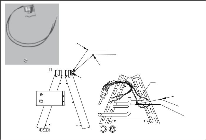
EXPANSION VALVE KITS
1/4 FLARE CONNECTION |
|
|
For Applications requiring |
||
|
|
a field installed access fitting |
|||
|
|
BULB TO BE LOCATED |
|||
|
|
AT 10 OR 2 O'CLOCK |
|||
SUCTION LINE |
BULB |
|
|
|
|
EVAPORATOR COIL |
|
|
|
|
|
|
SEAL SUPPLIED W/ KIT |
|
PISTON |
TAILPIECE |
|
|
|
|
|
||
SEAL SUPPLIED W/ KIT |
|
DISTRIBUTOR |
SEAL |
|
|
|
EXPANSION VALVE |
|
|||
|
|
BODY |
|
|
|
REMOVE BEFORE INSTALLING EXPANSION VALVE |
|
|
|
3/8"- |
|
|
|
|
|
|
|
|
|
|
|
|
SWEAT |
|
|
|
7/8" NUT |
|
|
1/4' FLARE |
|
|
For Applications not requiring |
||
CONNECTION |
|
|
a field installed access fitting |
||
|
|
|
|||
|
|
|
BULB TO BE LOCATED |
|
|
|
|
|
AT 10 OR 2 O'CLOCK |
|
|
|
BULB |
SUCTION LINE |
|
|
|
|
|
|
|
PISTON |
TAILPIECE |
EVAPORATOR COIL |
|
EXPANSION VALVE |
DISTRIBUTOR |
SEAL |
|
|
|
|
|||
|
|
BODY |
|
|
|
|
|
|
|
|
|
|
|
|
|
|
3/8"- |
|
|
|
|
|
SWEAT |
|
REMOVE BEFORE |
SEAL SUPPLIED W/ KIT |
|
|
|
SEAL SUPPLIED W/ KIT |
INSTALLING |
|
7/8" NUT |
|
|
EXPANSION VALVE |
|
|
|
||
|
|
|
|
|
|
21
ACCESSORIES
Wire Nut
|
la |
c |
k |
|
B |
|
|
||
|
|
k |
||
|
|
|
||
|
|
|
c |
|
|
|
|
la |
|
|
|
|
B |
|
FSK01A
FREEZETHERMOSTAT
KIT
Y
Y
Wire Nut
Install Line |
Install Line |
|
Thermostat |
||
Thermostat |
||
Here |
||
Here |
||
|
 Black
Black
Wire Nut
Y
|
|
|
|
|
|
|
|
|
|
|
|
|
Bl |
|
|
|
|
|
|
|
|
|
|
|
|
|
|
a |
|
|
|
|
|
|
|
|
|
|
|
|
|
|
c |
|
|
|
|
|
|
|
|
|
|
|
|
|
Wire Nut |
k |
|
|
|
|
|
|
|
|
|
|
|
|
|
|
||
|
|
|
|
|
|
|
|
|
|
|
|
|
|
|
|
|
|
|
|
|
|
|
|
|
|
|
|
|
|
|
|
|
|
|
|
|
|
|
|
|
|
|
|
|
Y
22
ACCESSORIES
|
|
|
|
|
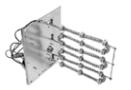
ELECTRICHEAT KIT |
|
|
|
|||
|
|
|
|
|
|
|
|
|
|
|
|
BLOWER |
HEATNO |
03*-HKR |
-HKR05(C)' |
06*-HKR |
08(C)*-HKR |
|
10(C)*-HKR |
15C*-HKA |
20C*-HKA |
-^HKR315* |
-^HKR320A |
|
|
|
|
|
|
|
|
|
|
|
|
|
|
|
|
|
|
|
|
|
|
|
|
MBVC1200AA-1** |
- |
X |
X |
X |
X |
|
X |
X |
- |
- |
- |
|
|
|
|
|
|
|
|
|
|
|
|
MBVC1600AA-1** |
- |
X |
X |
X |
X |
|
X |
X |
- |
- |
- |
|
|
|
|
|
|
|
|
|
|
|
|
MBVC2000AA-1** |
- |
X |
X |
X |
X |
|
X |
- |
X |
- |
- |
|
|
|
|
|
|
|
|
|
|
|
|
X =Allowable combinations |
^= Circuit 1: Single Phase for Air Handler Motor |
|
|
|
|
||||||
- = Restricted combinations |
Circuit 2: 3-Phase for HKR3 Heater Kits |
|
|
|
|
|
|||||
HK* SERIES ELETRIC HEAT KITS -
ELECTRIC HEAT KIT APPLICATIONS - MBVC
23
ACCESSORIES
ELECTRICHEATKITAPPLICATIONS - AVPTC
MODELS |
HKR-03* |
HKR-05*/-05C* |
HKR-06* |
HKR-08*/-08C* |
HKR-10*/-10C* |
HKR-15C* |
HKR-20C* |
HKR-21C* |
HKA-15C* |
HKA-20C* |
|
|
|
|
|
|
|
|
|
|
|
AVPTC183014A* |
X |
X |
X |
X1 |
X1 |
--- |
--- |
--- |
--- |
--- |
AVPTC313714A* |
X |
X |
X |
X1 |
X1 |
X2 |
--- |
--- |
X2 |
X |
AVPTC426014A* |
X |
X |
X |
X |
X |
X |
X3 |
X3 |
X |
X3 |
* Revision level that may or may not be designated.
C Circuit breaker option.
NOTE:
When 8kW and 10kW heat kits are used with an AVPTC1830 and AVPTC3137, matched with 2- ton outdoor unit, see Note 1 below.
1Set Heater Kit dip switches 9, 10 and 11 to 6kW setting (9-ON, 10-OFF,11-ON) to obtain 840 CFM.
2This heater kit can only be used for ‘1000 CFM or higher’ applications.
3This heater kit can only be used for ‘1200 CFM or higher’ applications.
24
ACCESSORIES
AVPTC**14**
Heat Kit Applications |
|
|
|
AVPTC |
|
|
|
|
|
|
|
|
|
|
|
Type / Model |
24B14-A* |
30C14-A* |
36C14-A* |
48C14-A* |
42D14-A*† |
48D14-A*†† |
60D14-A*††† |
HKSX03XC |
X |
X |
|
|
X |
|
|
HKSX05XC |
X |
X |
X |
X |
X |
X |
X |
|
|
|
|
|
|
|
|
HKSX06XC |
X |
X |
X |
X |
X |
X |
X |
|
|
|
|
|
|
|
|
HKSX08XC |
X |
X |
X |
X |
X |
X |
X |
|
|
|
|
|
|
|
|
HKSX10XC |
X |
X |
X |
X |
X |
X |
X |
|
|
|
|
|
|
|
|
HKSX15XF* |
|
|
X |
X |
X |
X |
X |
HKSX20XF* |
|
|
X |
X |
X |
X |
X |
HKSC05XC |
X |
X |
X |
X |
X |
X |
X |
|
|
|
|
|
|
|
|
HKSC08XC |
X |
X |
X |
X |
X |
X |
X |
|
|
|
|
|
|
|
|
HKSC10XC |
X |
X |
X |
X |
X |
X |
X |
|
|
|
|
|
|
|
|
HKSC15XA |
|
|
X |
X |
X |
X |
X |
HKSC15XB |
|
|
X |
X |
X |
X |
X |
HKSC15XF* |
|
|
X |
X |
X |
X |
X |
HKSC19CA* |
|
|
X |
X |
|
|
|
HKSC19CB* |
|
|
X |
X |
|
|
|
HKSC20DA |
|
|
|
|
X |
X |
X |
HKSC20DB |
|
|
|
|
X |
X |
X |
HKSCX20XF* |
|
|
X |
X |
X |
X |
X |
HKSC25DC* |
|
|
|
|
|
X |
X |
|
|
|
|
|
|
|
|
* Revision level that may or may not be designated.
Refer to the minimum airflow requirements for each of the heat kits.
†For match up with a 2 ton outdoor unit: Heater kit applica Ɵon shall not exceed 10 kW. Airflow for 5 kW up to 10 kW heater kits shall be set to 850 cfm speed tap of ON-ON-ON.
††For match up with a 3 ton outdoor unit: Heater kit applicaƟon shall not exceed 15 kW. Airflow for 5 kW up to 15 kW heater kits shall be set to 1400 cfm speed tap of ON-ON-OFF.
†††For match up with a 3.5 ton outdoor unit: Heater kit applica Ɵon shall not exceed 20 kW. Airflow for 5 kW up to 20 kW heater kits shall be set to 1620 cfm speed tap of ON-ON-OFF
** 3 kW heater kit is not applicable for this indoor application.
25

ACCESSORIES
READY 15 AVPTC
Model |
AVPTC25B14 |
AVPTC29B14 |
AVPTC31C14 |
AVPTC33C14 |
AVPTC35B14 |
AVPTC39C14 |
AVPTC37B14 |
AVPTC37C14 |
AVPTC37D14 |
AVPTC49C14 |
AVPTC49D14 |
AVPTC59C14 |
AVPTC59D14 |
AVPTC61D14 |
HKSX03XC |
X |
X |
|
X |
X |
|
X |
|
|
|
|
|
|
|
HKSX05XC |
X |
X |
X |
X |
X |
X |
X |
X |
X |
X |
X |
X |
X |
X |
HKSX06XC |
X |
X |
X |
X |
X |
X |
X |
X |
X |
X |
X |
X |
X |
X |
HKSX08XC |
X |
X |
X |
X |
X |
X |
X |
X |
X |
X |
X |
X |
X |
X |
|
|
|
|
|
|
|
|
|
|
|
|
|
|
|
HKSX10XC |
X |
X |
X |
X |
X |
X |
X |
X |
X |
X |
X |
X |
X |
X |
|
|
|
|
|
|
|
|
|
|
|
|
|
|
|
HKSC05XC |
X |
X |
X |
X |
X |
X |
X |
X |
X |
X |
X |
X |
X |
X |
HKSC08XC |
X |
X |
X |
X |
X |
X |
X |
X |
X |
X |
X |
X |
X |
X |
|
|
|
|
|
|
|
|
|
|
|
|
|
|
|
HKSC10XC |
X |
X |
X |
X |
X |
X |
X |
X |
X |
X |
X |
X |
X |
X |
HKSC15XA |
X |
X |
X |
X |
X |
X |
X |
X |
X |
X |
X |
|
|
|
HKSC15XB |
X |
X |
X |
X |
X |
X |
X |
X |
X |
X |
X |
X |
X |
X |
|
|
|
|
|
|
|
|
|
|
|
|
|
|
|
HKSC15XF |
|
|
X |
|
|
X |
|
X |
X |
X |
|
X |
X |
X |
HKSC19CA |
|
|
X |
|
|
X |
|
X |
|
X |
|
|
|
|
HKSC19CB |
|
|
X |
|
|
X |
|
X |
|
X |
|
X |
|
|
HKSC19CH |
|
|
|
|
|
|
|
|
|
|
|
X |
|
|
HKSC20DA |
|
|
|
|
|
|
|
|
X |
|
|
|
|
|
HKSC20DB |
|
|
|
|
|
|
|
|
X |
|
|
|
X |
X |
HKSC20DH |
|
|
|
|
|
|
|
|
|
|
|
|
X |
X |
HKSC20XF |
|
|
|
|
|
|
|
|
X |
|
|
X |
X |
X |
HKSC25DA |
|
|
|
|
|
|
|
|
|
|
|
|
|
X |
HKSC25DB |
|
|
|
|
|
|
|
|
|
|
|
|
|
X |
26
PRODUCT DESIGN
This section gives a basic description of cooling unit operation, its various components and their basic operation. Ensure your system is properly sized for heat gain and loss according to methods of the Air Conditioning Contractors Association (ACCA) or equivalent.
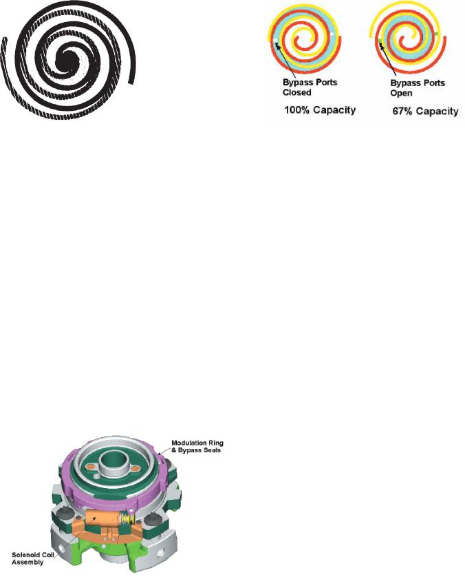
The ZPS two-step modulated scroll uses a single step of unloading to go from full capacity to approximately 67% capacity. A single speed, high efficiency motor continues to run while the scroll modulates between the two capacity steps.
CONDENSING UNIT
The condenser air is pulled through the condenser coil by a direct drive propeller fan. This condenser air is then discharged out of the top of the cabinet. These units are designed for free air discharge, so no additional resistance, like duct work, shall be attached.
The suction and liquid line connections on present models are of the sweat type for field piping with refrigerant type copper. Front seating valves are factory installed to accept the field run copper. The total refrigerant charge for a normal installation is factory installed in the condensing unit.
ASXC, ASZC, DSXC, DSZC models are available in 2 through 5 ton sizes and use R-410A refrigerant. They are designed for 208/230 volt single phase applications.
ASXC, ASZC, DSXC, DSZC R-410A model units use the Copeland Scroll "Ultratech" Series compressors which are specifically designed for R-410A refrigerant. These units also have Copeland® ComfortAlert diagnostics. The Copeland® ComfortAlert diagnostics are integrated into the unitary (UC) control. These models are ComfortNetTM ready.
There are a number of design characteristics which are different from the traditional reciprocating and/or scroll compressors.
"Ultractech" Series scroll compressors will not have a discharge thermostat. Some of the early model scroll compressors required discharge thermostat.
"Ultratech" Series scroll compressors use "POE" or polyolester oil which is NOT compatible with mineral oil based lubricants like 3GS. "POE" oil must be used if additional oil is required.
The ASXC [16 & 18], ASZC [16 & 18], DSXC [16 & 18] and DSZC [16 & 18] series split system units use a two-stage scroll compressor. The two-step modulator has an internal unloading mechanism that opens a bypass port in the first compression pocket, effectively reducing the displacement of the scroll. The opening and closing of the bypass port is controlled by an internal electrically operated solenoid.
FIGUREA
A scroll is an involute spiral which, when matched with a mating scroll form as shown, generates a series of crescent shaped gas pockets between the two members.
During compression, one scroll remains stationary (fixed scroll) while the other form (orbiting scroll) is allowed to orbit (but not rotate) around the first form.
As this motion occurs, the pockets between the two forms are slowly pushed to the center of the two scrolls while simultaneously being reduced in volume. When the pocket reaches the center of the scroll form, the gas, which is now at a high pressure, is discharged out of a port located at the center.
During compression, several pockets are being compressed simultaneously, resulting in a very smooth process. Both the suction process (outer portion of the scroll members) and the discharge process (inner portion) are continuous.
Some design characteristics of the Compliant Scroll compressor are:
•Compliant Scroll compressors are more tolerant of liquid refrigerant.
NOTE: Even though the compressor section of a Scroll compressor is more tolerant of liquid refrigerant, continued floodback or flooded start conditions may wash oil from the bearing surfaces causing premature bearing failure.
27
PRODUCT DESIGN
•Compliantscrollcompressorsperform"quiet"shutdowns that allow the compressor to restart immediately without the need for a time delay. This compressor will restart even if the system has not equalized.
NOTE: Operating pressures and amp draws may differ from standard reciprocating compressors. This information can be found in the unit's Technical Information Manual.
CAPACITY CONTROL - COMFORTNETTM MODELS
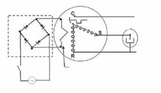
During the compression process, there are several pockets within the scroll that are compressing gas. Modulation is achieved by venting a portion of the gas in the first suction pocket back to the low side of the compressor thereby reducing the effective displacement of the compressor. See Figure A. Full capacity is achieved by blocking these vents, increasing the displacement to 100%. A solenoid in the compressor, controlled by an external 24-volt ac signal, moves the slider ring that covers and uncovers these vents. The vent covers are arranged in such a manner that the compressor operates somewhere around 67% capacity when the solenoid is not energized and 100% capacity when the solenoid is energized. The loading and unloading of the two step scroll is done “on the fly” without shutting off the motor between steps. See Figure C below. The unloaded mode default was chosen for two reasons:
Molded Plug*
Line
Run Capacitor
Line
Internal Unloader
Coil
24 vdc
*Rectifier is integrated on the UC PCB
FIGUREC
1.It is expected that the majority of run hours will be in the low capacity, unloaded mode.
2.It allows a simple two-stage thermostat to control capacity through the second stage in both cooling and possibly heating if desired.
UNLOADER SOLENOID
A nominal 24-volt direct current coil activates the internal unloader solenoid. The input control circuit voltage must be
18 to 28 volt ac. The coil power requirement is 20 VA. The external electrical connection is made with a molded plug assembly. This plug is connected to the Communicating Unitary Control PCB (UC PCB) which contains a full wave rectifier to supply direct current to the unloader coil.
COILS AND BLOWER COILS
MBVC blower cabinets are designed to be used as a twopiece blower and coil combination and can be utilized with the CAUF, CAPF and CAPT coils for upflow and downflow applications. The CACF and CHPF coils are designed for horizontal applications. This two-piece arrangement allows for a variety of mix-matching possibilities providing greater
flexibility.
The MBVC blower cabinets use a variable speed motor that maintains a constant airflow with a higher duct static. MBVC blower cabinets are approved for applications with cooling coils of up to 0.8 inches W.C. external static pressure. The MBVC models allow airflow trimming of +/-10%.
All units are constructed with R-4.2 insulation. In areas of extreme humidity (greater than 80% consistently), insulate the exterior of the blower with insulation having a vapor barrier equivalent to ductwork insulation, providing local codes permit.
AVPTC Multi-Position Air Handler
AVPTC is a multi-position, variable-speed air handler used with R-410A and are available in 2 to 5 ton sizes with optional 3 kW to 25kW electric heat kits available for field installation. The AVPTC unit’s blower design includes a variable-speed ECM motor and is compatible with heat pumps and variablecapacity cooling applications.
This appliance can be installed in the vertical or left horizontal positionwithoutmodification.Thehorizontalrightanddownflow positions require product modification. This product is designed for zero inches (0 inches) clearance; however, adequate access for service or replacement must be considered without removing permanent structure. This unit can be installed on a platform when deemed necessary.
In an attic installation a secondary drain pan must be provided by the installer and placed under the entire unit with a separate drain line properly sloped and terminated in an area visible to the owner. This secondary drain pan is required in the event that there is a leak or main drain blockage. Closed cell insulation should be applied to the drain lines in unconditioned spaces where sweating may occur.
28
PRODUCT DESIGN
NOTE: AVPTC air handlers are factory-sealed to achieve a 2% or less leakage rate at 1.0" water gauge external duct static pressure.
Communicating Unitary Control (UC) PCB
The Communicating System Unitary Control PCB is a micro- processor-based control for heat pump and air conditioning condensing units with single-phase compressors up to 5 ton capacity operating on standard residential or Delta and Wye commercial power. The control incorporates the basic functionality of existing defrost controls, outdoor thermostats, contactors, compressor staging controls, short cycle controls, line voltage monitors, Comfort Alert™ or CoreSense Module (dependent upon which module you are using), two speed condenser fan relays and the Active Protection component of enabled thermostats. The control is designed to work as part of a fully communicating HVAC system with 4 wires. The control also supports legacy 24VAC thermostat inputs for Y1, Y2, O and 24VAC outputs for RVS, W1, and L for non-communicating systems. Outputs include compressor power, compressor stage select, and outdoor fan high and outdoor fan low speed. System inputs include high/low pressure switches, as well as thermistor inputs for outdoor coil temperature and outdoor air temperature.
29
SYSTEM OPERATION
COOLING
The refrigerant used in the system is R-410A. It is a clear, colorless, non-toxic and non-irritating liquid. R-410A is a 50:50 blend of R-32 and R-125. The boiling point at atmospheric pressure is -62.9°F.
A few of the important principles that make the refrigeration cycle possible are: heat always flows from a warmer to a cooler body. Under lower pressure, a refrigerant will absorb heat and vaporize at a low temperature. The vapors may be drawn off and condensed at a higher pressure and temperature to be used again.
The indoor evaporator coil functions to cool and dehumidify the air conditioned spaces through the evaporative process taking place within the coil tubes.
NOTE: The pressures and temperatures shown in the refrigerant cycle illustrations on the following pages are for demonstration purposes only. Actual temperatures and pressures are to be obtained from the "Expanded Performance Chart".
Liquid refrigerant at condensing pressure and temperatures, (270 psig and 122°F), leaves the outdoor condensing coil through the drier and is metered into the indoor coil through the metering device. As the cool, low pressure, saturated refrigerant enters the tubes of the indoor coil, a portion of the liquid immediately vaporizes. It continues to soak up heat and vaporizes as it proceeds through the coil, cooling the indoor coil down to about 48°F.
Heat is continually being transferred to the cool fins and tubes of the indoor evaporator coil by the warm system air. This warming process causes the refrigerant to boil. The heat removed from the air is carried off by the vapor.
As the vapor passes through the last tubes of the coil, it becomes superheated. That is, it absorbs more heat than is necessary to vaporize it. This is assurance that only dry gas will reach the compressor. Liquid reaching the compressor can weaken or break compressor valves.
The compressor increases the pressure of the gas, thus adding more heat, and discharges hot, high pressure superheated gas into the outdoor condenser coil.
In the condenser coil, the hot refrigerant gas, being warmer than the outdoor air, first loses its superheat by heat transferred from the gas through the tubes and fins of the coil. The refrigerant now becomes saturated, part liquid, part vapor and then continues to give up heat until it condenses to a liquid alone. Once the vapor is fully liquefied, it continues to give up heat which subcools the liquid, and it is ready to repeat the cycle.
HEATING
The heating portion of the refrigeration cycle is similar to the cooling cycle. By energizing the reversing valve solenoid coil, the flow of the refrigerant is reversed. The indoor coil now becomes the condenser coil, and the outdoor coil becomes the evaporator coil.
The check valve at the indoor coil will open by the flow of refrigerant letting the now condensed liquid refrigerant bypass the indoor expansion device. The check valve at the outdoor coil will be forced closed by the refrigerant flow, thereby utilizing the outdoor expansion device.
COOLINGCYCLE
For communicating room thermostat: When the room thermostat calls for either low stage cool or high stage cool, appropriate commands are sent via the data 1 and data 2 lines to the outdoor unit's UC control. The UC control energizes the on-board compressor relay and the on-board outdoor fan relay. The compressor high stage solenoid is energized if it is a high stage call.
The UC control sends a fan command to the indoor unit (air handler or furnace). The indoor unit operates the indoor blower at the appropriate airflow level. The system operates at the cooling level demanded by the thermostat.
When the thermostat is satisfied, appropriate commands are sent to the UC control. The compressor relay and outdoor fan relay is de-energized. The compressor high stage solenoid is de-energized if it was energized. The UC control sends an appropriate command to the indoor unit to deenergize the indoor blower motor.
If room thermostat fan status is set to be “on”, then indoor blower would run continuously rather than cycling with the compressor.
For heat pumps, the reversing valve is energized during the cooling cycle. The call for cooling from the communicating thermostat indicates to the control that the reversing valve is to be energized during cooling operation.
HEATING CYCLE
For communicating room thermostat: When the room thermostat calls for either low stage heat or high stage heat, appropriate commands are sent via the data 1 and data 2 lines to the outdoor unit's UC control. The UC control energizes the on-board compressor relay and the on-board outdoor fan relay. The compressor high stage solenoid is energized if it is a high stage call. The UC control sends a fan command to the indoor unit (air handler or furnace). The indoor unit operates the indoor blower at the appropriate airflow level. The system operates at the cooling level demanded by the thermostat.
When the thermostat is satisfied, appropriate commands are sent to the UC control. The compressor relay and outdoor fan relay is de-energized. The compressor high stage solenoid is de-energized if it was energized. The UC control sends an appropriate command to the indoor unit to deenergize the indoor blower motor.
30
 Loading...