


 Loading...
Z490AORUSMASTER
User's Manual
Rev. 1001
12ME-Z49MSTR-1001R
For more product details, please visit GIGABYTE's website.
To reduce the impacts on global warming, the packaging materials of this product are recyclable and reusable. GIGABYTE works with you to protect the environment.
Copyright
© 2020 GIGA-BYTE TECHNOLOGY CO., LTD. All rights reserved.
The trademarks mentioned in this manual are legally registered to their respective owners.
Disclaimer
Information in this manual is protected by copyright laws and is the property of GIGABYTE.
Changes to the specifications and features in this manual may be made by GIGABYTE without prior notice.
No part of this manual may be reproduced, copied, translated, transmitted, or published in any form or by any means without GIGABYTE's prior written permission.
Documentation Classifications
In order to assist in the use of this product, GIGABYTE provides the following types of documentations:
For quick set-up of the product, read the Quick Installation Guide included with the product.
For detailed product information, carefully read the User's Manual.
For product-related information, check on our website at: https://www.gigabyte.com
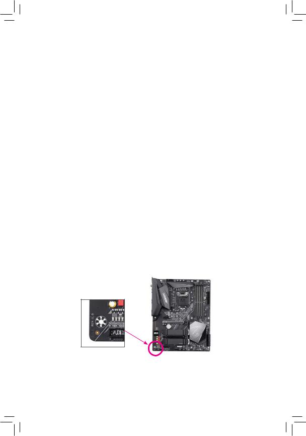
Identifying Your Motherboard Revision
The revision number on your motherboard looks like this: "REV: X.X." For example, "REV: 1.0" means the revision of the motherboard is 1.0. Check your motherboard revision before updating motherboard BIOS, drivers, or when looking for technical information.
Example:

Table of Contents
Box Contents................................................................................................................... |
|
|
5 |
Optional Items ................................................................................................................. |
|
5 |
|
Z490 AORUS MASTER Motherboard Layout ................................................................. |
6 |
||
Z490 AORUS MASTER Motherboard Block Diagram .................................................... |
7 |
||
Chapter 1 Hardware Installation ..................................................................................... |
9 |
||
1-1 |
Installation Precautions ................................................................................... |
9 |
|
1-2 |
Product Specifications................................................................................... |
10 |
|
1-3 |
Installing the CPU and CPU Cooler............................................................... |
14 |
|
|
1-3-1 |
Installing the CPU .................................................................................................. |
14 |
|
1-3-2 Installing the CPU Cooler ...................................................................................... |
16 |
|
1-4 |
Installing the Memory .................................................................................... |
17 |
|
|
1-4-1 Dual Channel Memory Configuration.................................................................... |
17 |
|
|
1-4-2 |
Installing a Memory................................................................................................ |
18 |
1-5 |
Installing an Expansion Card......................................................................... |
19 |
|
1-6 |
Setting up AMD CrossFire™/NVIDIA® SLI™ Configuration............................. |
20 |
|
1-7 |
Back Panel Connectors ................................................................................. |
21 |
|
1-8 |
Onboard Buttons, Switches and LEDs.......................................................... |
23 |
|
1-9 |
Internal Connectors ....................................................................................... |
25 |
|
Chapter 2 BIOS Setup .................................................................................................. |
39 |
||
2-1 |
Startup Screen............................................................................................... |
40 |
|
2-2 |
The Main Menu.............................................................................................. |
41 |
|
2-3 |
Favorites (F11) ............................................................................................... |
43 |
|
2-4 |
Tweaker.......................................................................................................... |
44 |
|
2-5 |
Settings.......................................................................................................... |
50 |
|
2-6 |
System Info. ................................................................................................... |
59 |
|
2-7 |
Boot................................................................................................................ |
60 |
|
2-8 |
Save & Exit .................................................................................................... |
63 |
|
Chapter 3 Configuring a RAID Set ............................................................................... |
65 |
||
3-1 |
Configuring SATA Controllers........................................................................ |
65 |
|
3-2 |
Installing the RAID/AHCI Driver and Operating System ............................... |
79 |
|
3-3 |
Installing an Intel® Optane™ Memory ............................................................. |
82 |
|
- 3 -

Chapter 4 Drivers Installation ....................................................................................... |
85 |
|
4-1 |
Drivers & Software......................................................................................... |
85 |
4-2 |
Application Software...................................................................................... |
86 |
4-3 |
Information..................................................................................................... |
86 |
Chapter 5 Unique Features........................................................................................... |
87 |
||
5-1 |
BIOS Update Utilities..................................................................................... |
87 |
|
5 |
-1-1 |
Updating the BIOS with the Q-Flash Utility........................................................... |
87 |
5 |
-1-2 |
Updating the BIOS with the @BIOS Utility........................................................... |
90 |
5 |
-1-3 |
Using Q-Flash Plus................................................................................................ |
91 |
5-2 |
APP Center.................................................................................................... |
92 |
|
5 |
-2-1 |
EasyTune................................................................................................................ |
93 |
5 |
-2-2 |
Fast Boot ............................................................................................................... |
94 |
5 |
-2-3 |
Game Boost .......................................................................................................... |
95 |
5 |
-2-4 |
RGB Fusion........................................................................................................... |
96 |
5 |
-2-5 |
Smart Backup ....................................................................................................... |
98 |
5 |
-2-6 |
System Information Viewer................................................................................. |
100 |
5 |
-2-7 |
USB TurboCharger .............................................................................................. |
101 |
Chapter 6 Appendix |
.................................................................................................... |
103 |
|
6-1 Configuring Audio Input and Output............................................................ |
103 |
||
6 |
-1-1 |
Configuring 2/4/5.1/7.1 - Channel Audio ................................................................ |
103 |
6 |
-1-2 ....................................................................................... |
Configuring S/PDIF Out |
105 |
6 |
-1-3 ........................................................................................................... |
Stereo Mix |
106 |
6 |
-1-4 .................................................................................... |
Using the Voice Recorder |
107 |
6 |
-1-5 ......................................................................................................... |
DTS:X ® Ultra |
108 |
6-2 |
Troubleshooting ............................................................................................ |
110 |
|
6 |
-2-1 ............................................................................... |
Frequently Asked Questions |
110 |
6 |
-2-2 ................................................................................. |
Troubleshooting Procedure |
111 |
6-3 |
Debug ........................................................................................LED Codes |
113 |
|
Regulatory ..................................................................................................Notices |
117 |
||
Contact Us .............................................................................................................. |
123 |
||
- 4 -
Box Contents
5Z490 AORUS MASTER motherboard
5Motherboard driver disc
5User's Manual
5Quick Installation Guide
5Four SATA cables
5One antenna
5Two RGB LED strip extension cables
5One noise detection cable
5Two thermistor cables
5One G Connector
The box contents above are for reference only and the actual items shall depend on the product package you obtain. The box contents are subject to change without notice.
Optional Items
2-port USB 2.0 bracket (Part No. 12CR1-1UB030-6*R)
eSATA bracket (Part No. 12CF1-3SATPW-4*R)
3.5" Front Panel with 2 USB 3.2 Gen 1 ports (Part No. 12CR1-FPX582-2*R)
- 5 -

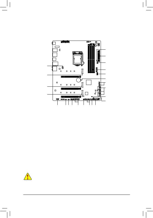
Z490 AORUS MASTER Motherboard Layout
CPU_FAN
SYS_FAN1 |
ATX_12V_2X4_2 |
REAR_BUTTON |
ATX_12V_2X4_1 |
|
|
CNVI_WIFI |
|
CPU_OPT |
LED_C2 |
|
D_LED2 |
||
|


 PW_SW
PW_SW
 DB_PORT (Note)
USB20 |
USB 2.0 Hub |
ATX |
LGA1200 |
HDMI |
U32 |
U32G2 |
U32G2C |
U32G2_LAN
SYS_FAN2
Z490 AORUS MASTER

PUMP |
EC TEMP1 |
SYSFAN6_ |
|
AUDIO
Intel® GbE LAN
110 |
80 |
60 |
42 |
PCIEX16
SB |
|
F U32 |
M2P_ |
DDR4 A1 DDR4 A2 DDR4 B1 DDR4 B2 |
F U32C |
BAT
ESS ES9118 DAC
110 |
80 |
60 |
42 |
Intel® Z490
M2A_CPU
THB_C1
THB_C2
PCIEX8
CODEC
110 |
80 |
60 |
42 |
PCIEX4
SB |
iTE® |
|
M2M |
||
Super I/O |


 USB 2.0 Hub
B_BIOS |
|
1 0 |
LED |
3 |
|
MBIOS_LED |
5 4 2 |
|
_ |
SATA3 |
|
M_BIOS |
BBIOS |
|
|
|
|
EC_TEMP2 |
|
|
CLR_CMOS |
|
|
|
|
|
|
|
|
|
|
|
|
|
|
|
|
|
|
|
|
|
|
|
|
|
|
|
|
|
|
|
|
|
|
|
|
|
|
|
|
|
|
|
|
|
|
|
|
|
|
|
|
|
|
|
|
|
|
|
|
|
|
|
|
|
|
|
|
|
|
|
|
|
|
|
|
|
|
|
|
F_AUDIO BIOS |
_SW |
|
|
D_ |
LED1 |
|
SPI_TPM |
|
F_ |
USB1 |
|
|
RST_ |
SW |
SYS_FAN4 |
|
|
F_ |
PANEL |
CPU |
DRAM |
|||||||||||||||||
|
|
|
|
|
|
SB |
LED_C1 |
F_USB2 |
NOISE_ |
SYS_FAN3 |
|
SYS_FAN5_ |
|
VGA |
BOOT |
|||||||||||||||||||||||
|
|
|
|
|
|
|
|
|
|
|
|
|
|
|
|
|
|
|
|
|
SENSOR |
|
|
|
|
|
|
PUMP |
|
|
|
|
|
|
||||
(Note) For debug code information, please refer to Chapter 6.
- 6 -
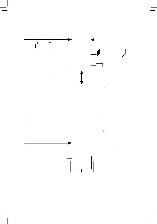
Z490 AORUS MASTER Motherboard Block Diagram
PCI Express 3.0 Bus
Switch
|
|
|
|
|
|
|
|
|
|
x16 |
|
|
|
x16 |
|||
|
|
|
|
|
|
|
|
|
ExpressPCI1 x16 |
|
or |
|
|
|
|
|
ExpressPCI2 x8 |
|
|
|
|
|
|
|||
|
|
|
|
|
|
|
|
|
|
|
|
|
|
|
|
|
|
|
|
|
|
|
|
|
|
|
|
|
|
|
|
|
|
|
|
|
|
|
|
|
|
|
|
|
|
|
|
|
|
|
|
|
|
CPU CLK+/- (100~500 MHz)
DDR4 3200/3000/2933/2666/2400/2133 MHz
LGA1200 CPU
DDI |
HDMI 1.4 |
|
DMI 3.0
PCI x4Express


x4
|
|
|
|
|
|
|
|
|
|
|
|
|
|
|
M2A_CPU |
|
|
|
|
|
|
|
SPI |
|
|
|
|
|
|
|
|
Dual BIOS |
|||||||||||||||
|
|
|
|
|
|
|
|
|
|
|
|
|
|
|
|
|
|
|
|
|
|
|
|
|
|
|
|
Bus |
|
|
|
|
|
|
|
|
TPM |
||||||||||
|
|
|
|
|
|
|
|
|
|
|
|
|
|
|
|
|
|
|
|
|
|
|
|
|
|
|
|
LPC |
|
|
|
|
|
|
|
|
|
||||||||||
|
|
|
|
|
|
|
|
|
|
|
|
|
|
|
|
|
|
|
|
|
|
|
|
|
|
|
|
|
|
|
|
|
|
|
|
|
|
|
|
|
|
|
|
|
|
|
|
|
|
|
|
|
|
|
|
|
|
|
|
|
|
|
M2P_SB |
|
|
|
|
|
|
|
|
|
|
iTE® |
|
|
|
|
|
|
|
|
|
|
|||||||||||
|
|
|
|
|
|
|
|
|
|
|
|
|
|
|
|
|
|
|
|
|
|
|
|
|
|
|
|
|
|||||||||||||||||||
|
|
|
|
|
|
|
|
|
|
|
|
|
|
|
|
|
|
|
|
|
|
Bus |
|
Super I/O |
|
|
|
|
|
|
|
|
|
|
|||||||||||||
|
|
|
|
|
|
|
|
|
|
|
|
|
|
|
|
|
|
|
|
|
|
|
|
|
|
|
|
|
|
|
|
|
|
|
|
|
|
|
|||||||||
|
|
|
|
|
|
|
|
|
|
|
|
|
|
|
|
|
|
|
|
|
|
|
|
|
|
|
|
|
|
|
|
|
|
|
|
|
|
|
|
|
|
|
|
||||
|
|
|
|
|
|
|
|
4 SATA 6Gb/s |
|
|
|
|
|
|
|
|
|
|
|
|
|
|
|
|
|
|
|
|
|
2 USB Type-C™, |
|||||||||||||||||
|
|
|
|
|
|
|
|
|
|
(SATA3 0~3) |
|
|
|
|
|
|
|
|
|
Intel® Z490 |
|
|
|
|
|
|
|
|
|
|
|
USB 3.2 Gen 2 |
|||||||||||||||
|
|
|
|
|
|
|
|
|
|
|
|
|
|
|
|
|
|
|
|
|
|
|
|
|
|
|
|
|
|
|
|
|
|
|
|
3 USB 3.2 Gen 2 |
|||||||||||
SATA3 |
|
|
|
|
|
|
M.2 CNVi |
|
|
|
|
|
|
|
|
|
|
|
|
|
|
Type A |
|||||||||||||||||||||||||
|
|
|
|
|
|
|
|
|
|
|
|
|
|
|
|
|
|
|
|
||||||||||||||||||||||||||||
|
|
|
|
|
|
WIFI |
|
|
|
|
|
|
|
|
|
|
|
|
|
|
|||||||||||||||||||||||||||
|
|
4/5 M2M_SB |
|
LAN |
|
|
|
|
|
|
|
|
|
|
|
|
|
|
|
|
|
|
|
|
|
|
|
|
|
||||||||||||||||||
|
|
|
|
|
|
|
|
|
|
|
|
|
|
|
|
|
|
|
|
|
|
|
|
|
|
|
|
||||||||||||||||||||
|
|
|
|
|
|
|
|
|
|
|
|
|
|
|
|
|
|
|
|
|
|
|
|
|
|
|
|
|
|
|
|
|
|||||||||||||||
|
|
|
|
|
|
|
|
|
|
|
|
|
|
|
|
|
|
|
|
|
|
|
|
|
|
|
|
|
|
|
|
|
|
|
|
|
|
|
|
|
|
|
|
|
|
|
|
|
|
|
|
|
or |
|
|
|
|
|
|
|
RJ45 |
|
|
|
|
|
|
|
|
|
|
|
|
|
|
|
|
|
|
|
|
|
4 USB 3.2 Gen 1 |
||||||||||||
|
|
|
|
|
|
|
|
|
|
|
|
|
|
|
|
|
|
|
|
|
|
|
|
|
|
|
|
|
|
|
|
|
|
|
|
|
|
||||||||||
|
|
|
|
|
|
|
|
|
|
|
|
|
|
Intel® |
|
|
|
|
|
|
|
|
|
|
|
|
|
|
|
|
|
|
|
|
|
|
|
|
|
|
|
|
|
||||
|
|
|
|
Switch |
|
|
|
|
|
|
|
|
|
|
|
|
|
|
|
|
|
|
|
|
|
|
|
|
|
|
|
|
|
|
|
|
|
||||||||||
|
|
|
|
|
|
|
2.5GbE LAN |
|
|
|
|
|
|
|
|
|
|
|
|
|
|
|
|
|
|
|
|
|
|
|
|
|
|
|
|
|
|||||||||||
|
|
|
|
x4 |
|
|
|
|
|
|
|
|
x1 |
|
|
|
|
|
|
|
|
|
|
|
|
|
|
|
|
USB 2.0 |
|
|
|
|
|
|
|
|
|
|
8 USB 2.0/1.1 |
||||||
|
|
|
|
|
|
|
|
|
|
|
|
|
|
|
|
|
|
|
|
|
|
|
|
|
|
|
|
|
|
|
|
||||||||||||||||
|
|
|
|
PCI Express 3.0 Bus |
|
|
|
|
|
|
|
|
|
|
|
|
|
|
Hub |
|
|
|
|
|
|
|
|
|
|
|
|||||||||||||||||
|
|
|
|
|
|
|
|
|
|
|
|
|
|
|
|
|
|
|
|
|
|
|
|
|
|
|
|
|
|
|
|
|
|
|
|
|
|
|
|
|
|
|
|
|
|
|
|
|
|
|
|
|
|
|
|
|
|
|
|
|
|
|
|
|
|
|
|
|
|
|
|
|
|
|
|
|
|
|
|
|
|
|
|
|
|
|
|
|
|
|
|
|
|
|
|
|
|
|
|
|
|
|
|
|
|
|
|
|
|
|
|
|
|
|
|
|
|
|
|
|
|
|
|
|
|
|
|
|
|
|
|
|
|
|
|
|
|
|
|
|
|
|
|
|
|
|
|
|
|
|
|
|
|
|
|
|
|
|
|
|
|
|
|
|
|
|
|
|
|
|
|
|
|
|
|
|
|
|
|
|
|
|
|
|
|
|
|
|
|
|
|
CODEC
+
ESS ES9118 DAC
SpeakerRearOut Center/Subwoofer |
MIC Line Out Line In |
S/PDIFOut |
SpeakerOut |
|
|
- 7 -

- 8 -

Chapter 1 Hardware Installation
1-1 Installation Precautions
The motherboard contains numerous delicate electronic circuits and components which can become damaged as a result of electrostatic discharge (ESD). Prior to installation, carefully read the user's manual and follow these procedures:
•Prior to installation, make sure the chassis is suitable for the motherboard.
•Prior to installation, do not remove or break motherboard S/N (Serial Number) sticker or warranty sticker provided by your dealer. These stickers are required for warranty validation.
•Always remove the AC power by unplugging the power cord from the power outlet before installing or removing the motherboard or other hardware components.
•When connecting hardware components to the internal connectors on the motherboard, make sure they are connected tightly and securely.
•When handling the motherboard, avoid touching any metal leads or connectors.
•It is best to wear an electrostatic discharge (ESD) wrist strap when handling electronic components such as a motherboard, CPU or memory. If you do not have an ESD wrist strap, keep your hands dry and first touch a metal object to eliminate static electricity.
•Prior to installing the motherboard, please have it on top of an antistatic pad or within an electrostatic shielding container.
•Before connecting or unplugging the power supply cable from the motherboard, make sure the power supply has been turned off.
•Before turning on the power, make sure the power supply voltage has been set according to the local voltage standard.
•Before using the product, please verify that all cables and power connectors of your hardware components are connected.
•To prevent damage to the motherboard, do not allow screws to come in contact with the motherboard circuit or its components.
•Make sure there are no leftover screws or metal components placed on the motherboard or within the computer casing.
•Do not place the computer system on an uneven surface.
•Do not place the computer system in a high-temperature or wet environment.
•Turning on the computer power during the installation process can lead to damage to system components as well as physical harm to the user.
•If you are uncertain about any installation steps or have a problem related to the use of the product, please consult a certified computer technician.
•If you use an adapter, extension power cable, or power strip, ensure to consult with its installation and/or grounding instructions.
- 9 - |
Hardware Installation |
1-2 |
Product Specifications |
|
|
|
|
|
CPU |
Support for 10th Generation Intel® Core™ i9 processors/Intel® Core™ i7 processors/ |
Intel® Core™ i5 processors/Intel® Core™ i3 processors/Intel® Pentium® processors/ Intel® Celeron® processors in the LGA1200 package
(Go to GIGABYTE's website for the latest CPU support list.)
L3 cache varies with CPU
Chipset |
|
Intel® Z490 Express Chipset |
Memory |
|
Intel® Core™ i9/i7 processors: |
|
|
- Support for DDR4 3200/2933/2666/2400/2133 MHz memory modules |
|
|
Intel® Core™ i5/i3/Pentium®/Celeron® processors: |
|
|
- Support for DDR4 2666/2400/2133 MHz memory modules |
|
4 x DDR4 DIMM sockets supporting up to 128 GB (32 GB single DIMM capacity) |
|
|
|
of system memory |
|
Dual channel memory architecture |
|
|
Support for ECC Un-buffered DIMM 1Rx8/2Rx8 memory modules (operate in |
|
|
|
non-ECC mode) |
|
Support for non-ECC Un-buffered DIMM 1Rx8/2Rx8/1Rx16 memory modules |
|
|
Support for Extreme Memory Profile (XMP) memory modules |
|
|
|
(Go to GIGABYTE's website for the latest supported memory speeds and memory |
|
|
modules.) |
Onboard |
|
Integrated Graphics Processor-Intel® HD Graphics support: |
Graphics |
|
- 1 x HDMI port, supporting a maximum resolution of 4096x2160@30 Hz |
*Support for HDMI 1.4 version and HDCP 2.3.
Maximum shared memory of 512 MB
Audio |
|
Realtek® ALC1220-VB codec |
|
|
|
|
* The front panel line out jack supports DSD audio. |
|
ESS ES9118EQ DAC chip |
||
|
Support for DTS:X® Ultra |
||
|
|
High Definition Audio |
|
|
|
2/4/5.1/7.1-channel |
|
|
Support for S/PDIF Out |
||
LAN |
|
Intel® 2.5GbE LAN chip (2.5 Gbit/1 Gbit/100 Mbit) |
|
Wireless |
|
Intel® Wi-Fi 6 AX201 |
|
Communication |
|
- |
WIFI a, b, g, n, ac with wave 2 features, ax, supporting 2.4/5 GHz Dual-Band |
Module |
|
- |
BLUETOOTH 5.0 |
|
|
- |
Support for 11ax 160MHz wireless standard and up to 2.4 Gbps data rate |
|
|
|
* Actual data rate may vary depending on environment and equipment. |
Expansion Slots |
|
1 x PCI Express x16 slot, running at x16 (PCIEX16) |
|
|
|
|
* For optimum performance, if only one PCI Express graphics card is to be installed, |
|
|
|
be sure to install it in the PCIEX16 slot. |
|
1 x PCI Express x16 slot, running at x8 (PCIEX8) |
||
|
|
|
* The PCIEX8 slot shares bandwidth with the PCIEX16 slot. When the PCIEX8 slot is |
|
|
|
populated, the PCIEX16 slot operates at up to x8 mode. |
|
1 x PCI Express x16 slot, running at x4 (PCIEX4) |
||
|
|
(All of the PCI Express slots conform to PCI Express 3.0 standard.) |
|
Multi-Graphics |
|
Support for NVIDIA® Quad-GPU SLI™ and 2-Way NVIDIA® SLI™ technologies |
|
Technology |
|
Support for AMD Quad-GPU CrossFire™ and 2-Way AMD CrossFire™ technologies |
|
|
|
|
|
Hardware Installation |
|
|
- 10 - |
Storage Interface 1 x M.2 connector (Socket 3, M key, type 2242/2260/2280/22110 PCIe x4/x2 SSD support) (M2P_SB)
1 x M.2 connector (Socket 3, M key, type 2242/2260/2280/22110 SATA and PCIe x4/x2 SSD support) (M2A_CPU)
1 x M.2 connector (Socket 3, M key, type 2242/2260/2280/22110 SATA and PCIe x4/x2 SSD support) (M2M_SB)
6 x SATA 6Gb/s connectors
Support for RAID 0, RAID 1, RAID 5, and RAID 10
*Refer to "1-9 Internal Connectors," for the installation notices for the M.2 and SATA connectors.
Intel® Optane™ Memory Ready
USB |
Chipset: |
|
- 2 x USB Type-C™ ports, with USB 3.2 Gen 2 support (1 port on the back panel, |
|
1 port available through the internal USB header) |
|
- 3 x USB 3.2 Gen 2 Type-A ports (red) on the back panel |
|
- 4 x USB 3.2 Gen 1 ports (2 ports on the back panel, 2 ports available through |
|
the internal USB header) |
|
Chipset+2 USB 2.0 Hubs: |
|
- 8 x USB 2.0/1.1 ports (4 ports on the back panel, 4 ports available through |
|
the internal USB headers) |
Internal |
1 x 24-pin ATX main power connector |
Connectors |
2 x 8-pin ATX 12V power connectors |
1 x CPU fan header
1 x water cooling CPU fan header
4 x system fan headers
2 x system fan/water cooling pump headers
2 x addressable LED strip headers
2 x RGB LED strip headers
3 x M.2 Socket 3 connectors
6 x SATA 6Gb/s connectors
1 x front panel header
1 x front panel audio header
1 x USB Type-C™ header, with USB 3.2 Gen 2 support
1 x USB 3.2 Gen 1 header
2 x USB 2.0/1.1 headers
1 x noise detection header
2 x Thunderbolt™ add-in card connectors
1 x Trusted Platform Module header (For the GC-TPM2.0 SPI/GC-TPM2.0 SPI 2.0 module only)
1 x power button
1 x reset button
2 x temperature sensor headers
1 x Clear CMOS jumper
2 x BIOS switches
- 11 - |
Hardware Installation |
Back Panel |
|
1 x Q-Flash Plus button |
Connectors |
|
1 x Clear CMOS button |
|
2 x SMA antenna connectors (2T2R) |
|
|
1 x HDMI port |
|
|
1 x USB Type-C™ port, with USB 3.2 Gen 2 support |
|
|
3 x USB 3.2 Gen 2 Type-A ports (red) |
|
|
2 x USB 3.2 Gen 1 ports |
|
|
4 x USB 2.0/1.1 ports |
|
|
1 x RJ-45 port |
|
|
1 x optical S/PDIF Out connector |
|
|
5 x audio jacks |
|
I/O Controller |
|
iTE® I/O Controller Chip |
Hardware |
|
Voltage detection |
Monitor |
|
Temperature detection |
|
|
Fan speed detection |
|
Water cooling flow rate detection |
|
|
|
Overheating warning |
|
|
Fan fail warning |
|
|
Fan speed control |
|
|
* Whether the fan (pump) speed control function is supported will depend on the fan |
|
|
(pump) you install. |
|
|
Noise detection |
BIOS |
|
2 x 256 Mbit flash |
|
|
Use of licensed AMI UEFI BIOS |
Support for DualBIOS™
PnP 1.0a, DMI 2.7, WfM 2.0, SM BIOS 2.7, ACPI 5.0
Unique Features Support for APP Center
|
* Available applications in APP Center may vary by motherboard model. Supported |
|
functionsofeachapplicationmayalsovarydependingonmotherboardspecifications. |
- |
@BIOS |
- |
EasyTune |
- |
Fast Boot |
- |
Game Boost |
- |
RGB Fusion |
- |
Smart Backup |
- |
System Information Viewer |
- |
USB TurboCharger |
Support for Q-Flash PlusSupport for Q-Flash
Support for Xpress Install
Hardware Installation |
- 12 - |
Bundled |
|
Norton® Internet Security (OEM version) |
|
Software |
|
cFosSpeed |
|
|
XSplit Gamecaster + Broadcaster (12 months license) |
||
Operating |
|
Support for Windows 10 64-bit |
|
System |
|||
|
|
||
Form Factor |
|
ATX Form Factor; 30.5cm x 24.4cm |
|
*GIGABYTE reserves the right to make any changes to the product specifications and product-related information without prior notice.
Please visit GIGABYTE's website for support lists of CPU, memory modules, SSDs, and M.2 devices.
- 13 -
Please visit the Support\Utility List page on GIGABYTE's website to download the latest version of apps.
Hardware Installation
1-3 Installing the CPU and CPU Cooler
Read the following guidelines before you begin to install the CPU:
•Make sure that the motherboard supports the CPU.
(Go to GIGABYTE's website for the latest CPU support list.)
•Always turn off the computer and unplug the power cord from the power outlet before installing the CPU to prevent hardware damage.
•Locate the pin one of the CPU. The CPU cannot be inserted if oriented incorrectly. (Or you may locate the notches on both sides of the CPU and alignment keys on the CPU socket.)
•Apply an even and thin layer of thermal grease on the surface of the CPU.
•Do not turn on the computer if the CPU cooler is not installed, otherwise overheating and damage of the CPU may occur.
•Set the CPU host frequency in accordance with the CPU specifications. It is not recommended that the system bus frequency be set beyond hardware specifications since it does not meet the standard requirements for the peripherals. If you wish to set the frequency beyond the standard specifications, please do so according to your hardware specifications including the CPU, graphics card, memory, hard drive, etc.
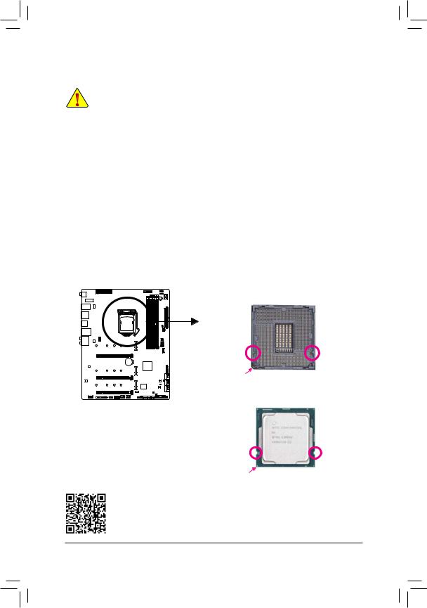
1-3-1 Installing the CPU
A. Locate the alignment keys on the motherboard CPU socket and the notches on the CPU.
LGA1200 CPU Socket
Alignment |
Alignment |
Key |
Key |
Pin One Corner of the CPU Socket |
|
LGA1200 CPU
Notch |
Notch |
Triangle Pin One Marking on the CPU
Please visit GIGABYTE's website for details on hardware installation.
Hardware Installation |
- 14 - |
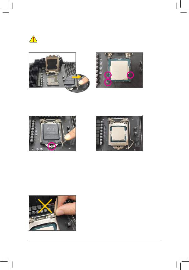
B.Follow the steps below to correctly install the CPU into the motherboard CPU socket.
•Before installing the CPU, make sure to turn off the computer and unplug the power cord from the power outlet to prevent damage to the CPU.
•To protect the socket contacts, do not remove the protective plastic cover unless the CPU is inserted into the CPU socket. Save the cover properly and replace it if the CPU is removed.
Step 1:
Gently press the CPU socket lever handle down and away from the socket with your finger. Then completely lift the CPU socket lever and the metal load plate/plastic cover will be lifted as well.
Step 3:
Once the CPU is properly inserted, carefully replace the load plate. When replacing the load plate, make sure the front end of the load plate is under the shoulder screw. Then press the CPU socket lever. The protective plastic cover may pop off from the load plate during the process of engaging the lever. Remove the cover. (Save the cover properly and always replace it when the CPU is not installed.)
Step 2:
Hold the CPU with your thumb and index fingers.
Align the CPU pin one marking (triangle) with the pin one corner of the CPU socket (or you may align the CPU notches with the socket alignment keys) and gently insert the CPU into position.
Step 4:
Finally, secure the lever under its retention tab to complete the installation of the CPU.
NOTE:
Hold the CPU socket lever by the handle, not the lever base portion.
- 15 - |
Hardware Installation |
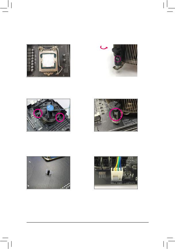
1-3-2 Installing the CPU Cooler
Refer to the steps below to correctly install the CPU cooler on the motherboard. (Actual installation process may differ depending the CPU cooler to be used. Refer to the user's manual for your CPU cooler.)
Step 1:
Apply an even and thin layer of thermal grease on the surface of the installed CPU.
Step 3:
Place the cooler atop the CPU, aligning the four push pins through the pin holes on the motherboard. Push down on the push pins diagonally.
|
|
|
|
|
Male |
|
|
|
|
|
|
Direction of |
|
Push Pin |
|||
the Arrow Sign |
|
|
|||
on the Male |
|
|
|||
Push Pin |
|
|
The Top |
||
|
|
||||
|
|
|
|
|
of Female |
|
|
|
|
|
Push Pin |
|
|
|
|
|
Female |
|
|
|
|
|
|
|
|
|
|
|
Push Pin |
|
|
|
|
|
|
Step 2:
Before installing the cooler, note the direction of the arrow sign  on the male push pin. (Turning the push pin along the direction of arrow is to remove the cooler, on the contrary, is to install.)
Step 4:
You should hear a "click" when pushing down each push pin. Check that the Male and Female push pins are joined closely.
(Refer to your CPU cooler installation manual for instructions on installing the cooler.)
Step 5:
After the installation, check the back of the motherboard. If the push pin is inserted as the picture above shows, the installation is complete.
Step 6:
Finally, attach the power connector of the CPU cooler to the CPU fan header (CPU_FAN) on the motherboard.
Hardware Installation |
- 16 - |
1-4 Installing the Memory
Read the following guidelines before you begin to install the memory:
•Make sure that the motherboard supports the memory. It is recommended that memory of the same capacity, brand, speed, and chips be used.
(Go to GIGABYTE's website for the latest supported memory speeds and memory modules.)
•Always turn off the computer and unplug the power cord from the power outlet before installing the memory to prevent hardware damage.
•Memory modules have a foolproof design. A memory module can be installed in only one direction. If you are unable to insert the memory, switch the direction.
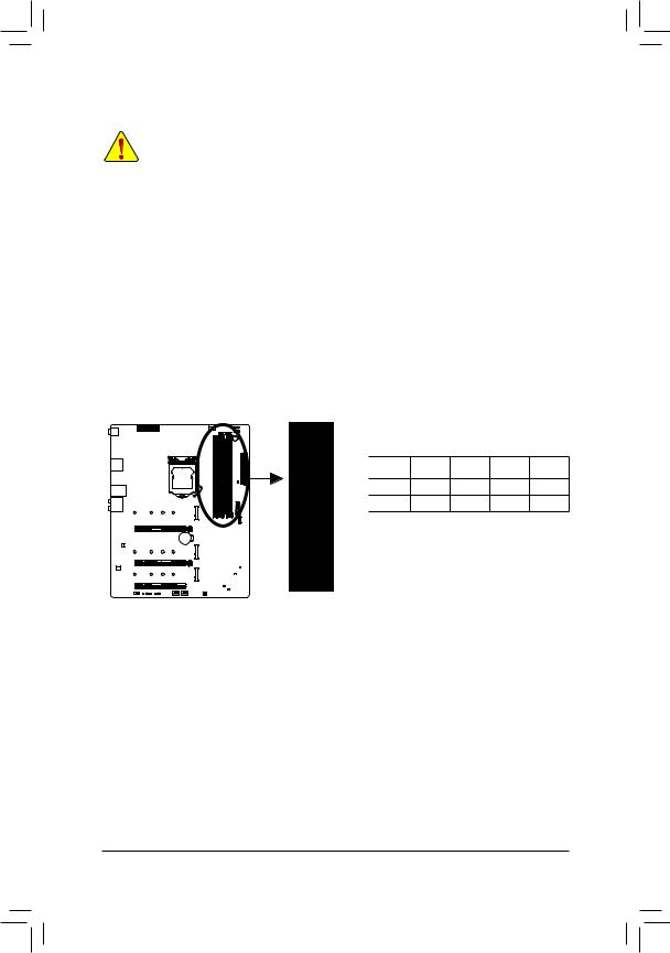
1-4-1 Dual Channel Memory Configuration
This motherboard provides four memory sockets and supports Dual Channel Technology. After the memory is installed, the BIOS will automatically detect the specifications and capacity of the memory. Enabling Dual
Channel memory mode will double the original memory bandwidth.
The four memory sockets are divided into two channels and each channel has two memory sockets as following:
Channel A: DDR4_A1, DDR4_A2Channel B: DDR4_B1, DDR4_B2
Recommanded Dual Channel Memory Configuration:
|
DDR4_A1 |
DDR4_A2 DDR4_B1 |
DDR4_B2 |
|
2 Modules |
- - |
DS/SS |
- - |
DS/SS |
4 Modules |
DS/SS |
DS/SS |
DS/SS |
DS/SS |
(SS=Single-Sided, DS=Double-Sided, "- -"=No Memory)
DDR4_B2
DDR4_B1
DDR4_A2
DDR4_A1
Due to CPU limitations, read the following guidelines before installing the memory in Dual Channel mode.
1.Dual Channel mode cannot be enabled if only one memory module is installed.
2.When enabling Dual Channel mode with two or four memory modules, it is recommended that memory of the same capacity, brand, speed, and chips be used.
- 17 - |
Hardware Installation |
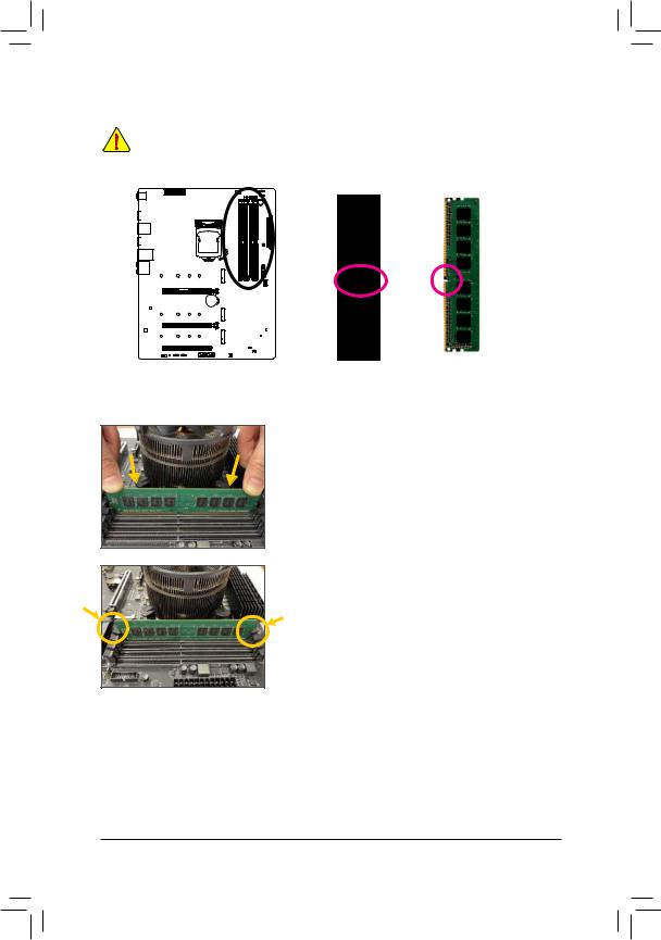
1-4-2 Installing a Memory
Before installing a memory module, make sure to turn off the computer and unplug the power cord from the power outlet to prevent damage to the memory module. DDR4 and DDR3 DIMMs are not compatible to each other or DDR2 DIMMs. Be sure to install DDR4 DIMMs on this motherboard.
Notch
DDR4 DIMM
ADDR4 memory module has a notch, so it can only fit in one direction. Follow the steps below to correctly install your memory modules in the memory sockets.
Step 1:
Note the orientation of the memory module. Spread the retaining clips at both ends of the memory socket. Place the memory module on the socket. As indicated in the picture on the left, place your fingers on the top edge of the memory, push down on the memory and insert it vertically into the memory socket.
Step 2:
The clips at both ends of the socket will snap into place when the memory module is securely inserted.
Hardware Installation |
- 18 - |
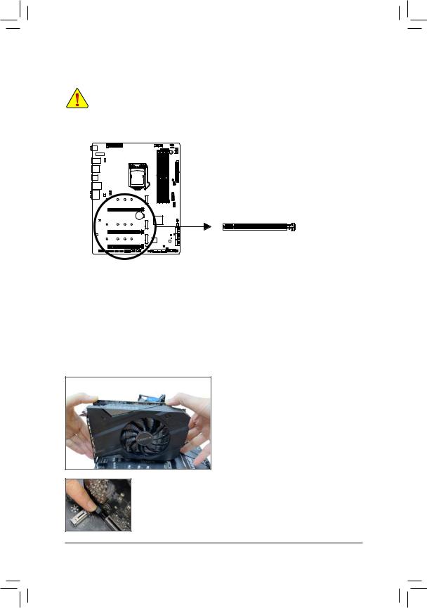
1-5 Installing an Expansion Card
Read the following guidelines before you begin to install an expansion card:
•Make sure the motherboard supports the expansion card. Carefully read the manual that came with your expansion card.
•Always turn off the computer and unplug the power cord from the power outlet before installing an expansion card to prevent hardware damage.
PCI Express x16 Slot
Follow the steps below to correctly install your expansion card in the expansion slot.
1.Locate an expansion slot that supports your card. Remove the metal slot cover from the chassis back panel.
2.Align the card with the slot, and press down on the card until it is fully seated in the slot.
3.Make sure the metal contacts on the card are completely inserted into the slot.
4.Secure the card's metal bracket to the chassis back panel with a screw.
5.After installing all expansion cards, replace the chassis cover(s).
6.Turn on your computer. If necessary, go to BIOS Setup to make any required BIOS changes for your expansion card(s).
7.Install the driver provided with the expansion card in your operating system.
Example: Installing and Removing a PCI Express Graphics Card:
• Installing a Graphics Card:
Gently push down on the top edge of the card until it is fully inserted into the PCI Express slot. Make sure the card is securely seated in the slot and does not rock.
•Removing the Card:
Gently push back on the lever on the slot and then lift the card straight out from the slot.
- 19 - |
Hardware Installation |
1-6 Setting up AMD CrossFire™/NVIDIA® SLI™ Configuration
A.System Requirements
-Windows 10 64-bit operating system
-A CrossFire/SLI-supported motherboard with two PCI Express x16 slots and correct driver
-CrossFire/SLI-ready graphics cards of identical brand and chip and correct driver
-CrossFire(Note)/SLI bridge connectors
-A power supply with sufficient power is recommended (Refer to the manual of your graphics cards for the power requirement)
B.Connecting the Graphics Cards
Step 1:
Observe the steps in "1-5 Installing an Expansion Card" and install the graphics cards on the PCIEX16 and PCIEX8 slots.
Step 2:
Insert the CrossFire (Note)/SLI bridge connectors in the CrossFire/SLI gold edge connectors on top of the cards. Step 3:
Plug the display cable into the graphics card on the PCIEX16 slot.
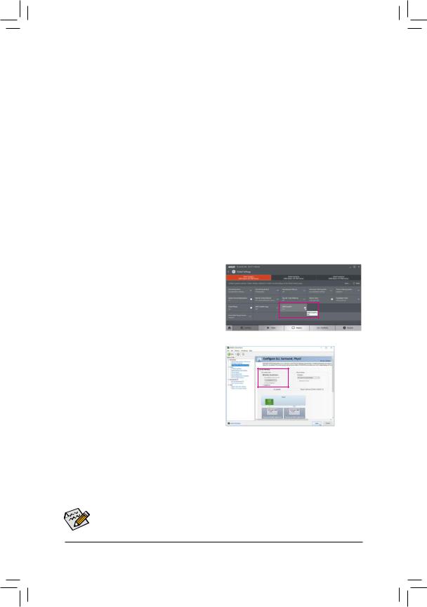
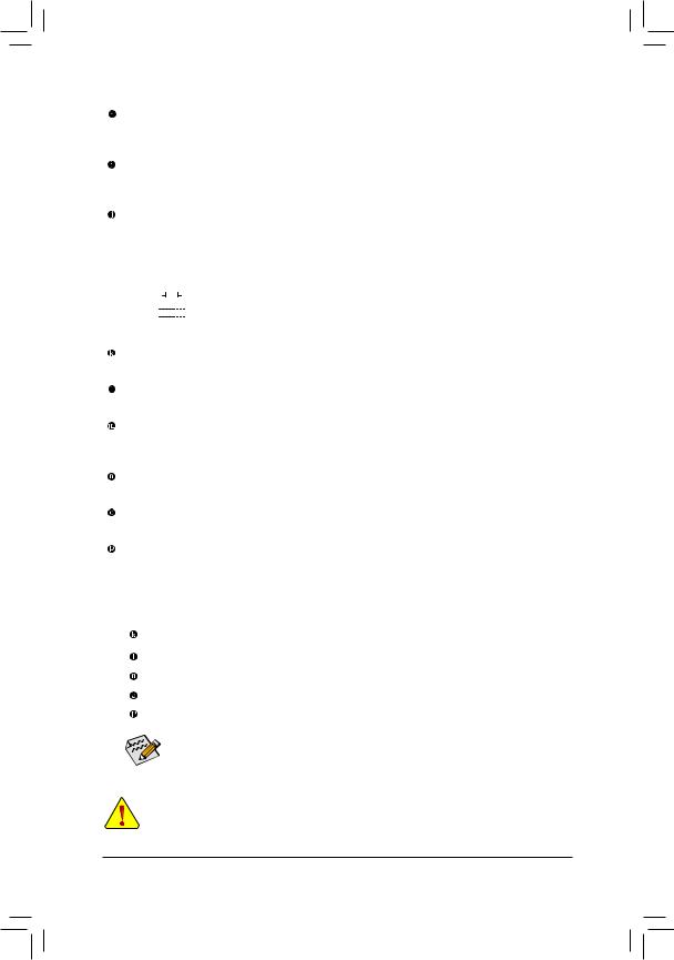
C. Configuring the Graphics Card Driver
C-1. To Enable CrossFire Function
After installing the graphics card driver in the operating system, go to the AMD RADEON SETTINGS screen. Browse to Gaming\Global Settings and ensure AMD CrossFire is set to On.
C-2. To Enable SLI Function
After installing the graphics card driver in the operating system, go to the NVIDIA Control Panel. Browse to the
Configure SLI, Surround, PhysX screen and ensure
Maximize 3D performance is enabled.
(Note) The bridge connector(s) may be needed or not depending on your graphics cards.
Procedure and driver screen for enabling CrossFire/SLI technology may differ by graphics cards and driver version. Refer to the manual that came with your graphics cards for more information about enabling CrossFire/SLI technology.
Hardware Installation |
- 20 - |
1-7 Back Panel Connectors
Q-Flash Plus Button (Note)
This button allows you to update the BIOS when the power connector is connected but the system is not powered on.
Clear CMOS Button
Use this button to clear the CMOS values (e.g. BIOS configuration) and reset the CMOS values to factory defaults when needed.
•Always turn off your computer and unplug the power cord from the power outlet before using the clear CMOS button.
•Do not use the clear CMOS button when the system is on, or the system may shutdown and data loss or damage may occur.
•After system restart, go to BIOS Setup to load factory defaults (select Load Optimized Defaults) or manuallyconfiguretheBIOSsettings(refertoChapter2,"BIOSSetup,"forBIOSconfigurations).
SMA Antenna Connectors (2T2R)
Use this connector to connect an antenna.
 Tighten the antennas to the antenna connectors and then aim the antennas correctly for better signal reception.
USB 2.0/1.1 Port
The USB port supports the USB 2.0/1.1 specification. Use this port for USB devices.
USB 3.2 Gen 1 Port
The USB 3.2 Gen 1 port supports the USB 3.2 Gen 1 specification and is compatible to the USB 2.0 specification. Use this port for USB devices.
USB 3.2 Gen 1 Port (Q-Flash Plus Port)
The USB port supports the USB 3.2 Gen 1 specification. Use this port for USB devices. Before using Q-Flash Plus (Note), make sure to insert the USB flash drive into this port first.
HDMI Port
 The HDMI port supports HDCP 2.3 and Dolby TrueHD and DTS HD Master Audio


 formats. It also supports up to 192KHz/16bit 7.1-channel LPCM audio output. You can use this port to connect your HDMI-supported monitor. The maximum supported resolution is 4096x2160@30 Hz, but the actual resolutions supported are dependent on the monitor being used.

 After installing the HDMI device, make sure to set the default sound playback device to HDMI.
  (The item name may differ depending on your operating system.)
(Note) To enable Q-Flash Plus function, refer to Chapter 5, "Unique Features," for more information.
- 21 - Hardware Installation
USB 3.2 Gen 2 Type-A Port (Red)
The USB 3.2 Gen 2 Type-A port supports the USB 3.2 Gen 2 specification and is compatible to the USB 3.2 Gen 1 and USB 2.0 specification. Use this port for USB devices.
USB Type-C™ Port
The reversible USB port supports the USB 3.2 Gen 2 specification and is compatible to the USB 3.2 Gen 1 and USB 2.0 specification. Use this port for USB devices.
RJ-45 LAN Port
The Gigabit Ethernet LAN port provides Internet connection at up to 2.5 Gbps data rate. The following describes the states of the LAN port LEDs.
Connection/ |
|
|
|
Activity LED |
Connection/Speed LED: |
|
Activity LED: |
|
||||||
Speed LED |
|
|
|
|
|
|||||||||
|
|
|
|
|
|
|
|
|||||||
|
|
|
|
|
|
|
|
|
|
State |
Description |
|
State |
Description |
|
|
|
|
|
|
|
|
|
|
Green |
2.5 Gbps data rate |
|
Blinking |
Data transmission or receiving is occurring |
|
|
|
|
|
|
|
|
|
|
|||||
|
|
|
|
|
|
|
|
|
|
Orange |
1 Gbps data rate |
|
On |
No data transmission or receiving is occurring |
|
|
|
|
|
|
|
|
|
|
|||||
|
|
|
|
|
|
|
|
|
|
Off |
100 Mbps data rate |
|
|
|
|
|
|
|
|
|
|
|
|
|
|
|
|
||
|
|
LAN Port |
|
|
|
|||||||||
|
|
|
|
|
|
|
||||||||
Center/Subwoofer Speaker Out
Use this audio jack to connect center/subwoofer speakers.
Rear Speaker Out
Use this audio jack to connect rear speakers.
Optical S/PDIF Out Connector
This connector provides digital audio out to an external audio system that supports digital optical audio. Before using this feature, ensure that your audio system provides an optical digital audio in connector.
Line In/Side Speaker Out
The line in jack. Use this audio jack for line in devices such as an optical drive, walkman, etc.
Line Out/Front Speaker Out
The line out jack.
Mic In/Side Speaker Out
The Mic in jack.
Audio Jack Configurations:
Jack |
Headphone/ |
4-channel |
5.1-channel |
7.1-channel |
|
2-channel |
|||||
|
|
|
|
||
Center/Subwoofer Speaker |
|
|
a |
a |
|
Out |
|
|
|||
|
|
|
|
||
Rear Speaker Out |
|
a |
a |
a |
|
|
|
|
|
|
|
Line In/Side Speaker Out |
|
|
|
a |
|
|
|
|
|
|
|
Line Out/Front Speaker Out |
a |
a |
a |
a |
|
|
|
|
|
|
|
Mic In/Side Speaker Out |
|
|
|
a |
|
|
|
|
|
|
If you want to install a Side Speaker, you need to retask either the Line in or Mic in jack to be Side Speaker out through the audio driver.
•When removing the cable connected to a back panel connector, first remove the cable from your device and then remove it from the motherboard.
•When removing the cable, pull it straight out from the connector. Do not rock it side to side to prevent an electrical short inside the cable connector.
Hardware Installation |
- 22 - |
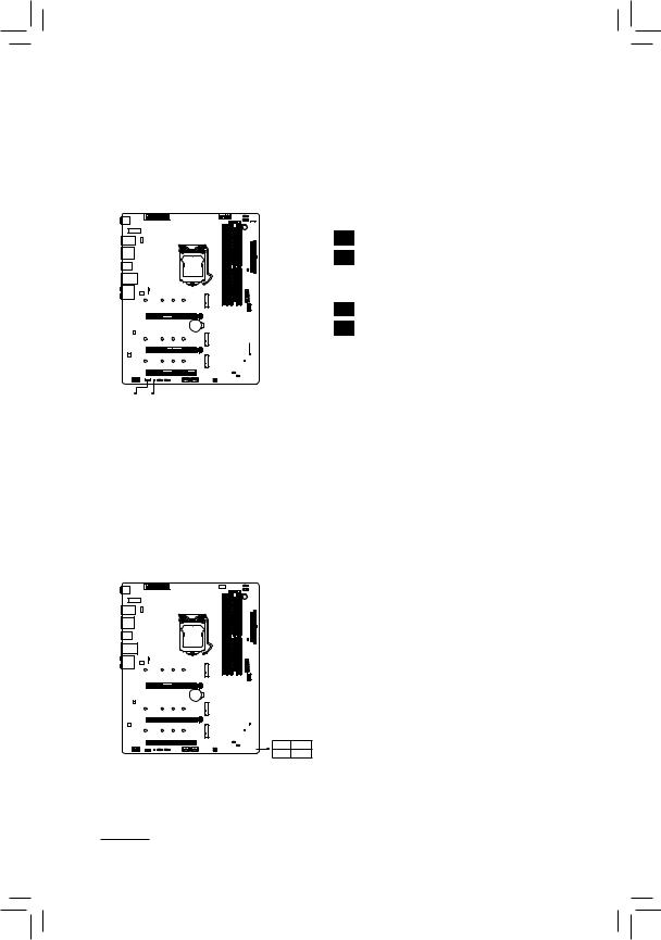
1-8 Onboard Buttons, Switches and LEDs
BIOS Switches and BIOS LED Indicators
The BIOS switch (BIOS_SW) allows users to easily select a different BIOS for boot up or overclocking, helping to reduce BIOS failure during overclocking. The SB switch allows enabling or disabling of the Dual BIOS function. The LED indicator (MBIOS_LED/BBIOS_LED) shows which BIOS is active.
BIOS_SW |
|
|
2 |
1 |
1: Main BIOS (Boot from the main BIOS) |
2 |
1 |
2: Backup BIOS (Boot from the backup BIOS) |
SB |
|
|
2 |
1 |
1: Dual BIOS |
2 |
1 |
2: Single BIOS |
 BBIOS_LED

 MBIOS_LED
BIOS_SW SB
BIOS LED Indicators:
MBIOS_LED (The main BIOS is active) BBIOS_LED (The backup BIOS is active)
 Before setting the SB switch, be sure to turn off your computer and power supply.
Status LEDs
The status LEDs show whether the CPU, memory, graphics card, and operating system are working properly after system power-on. If the CPU/DRAM/VGA LED is on, that means the corresponding device is not working normally; if the BOOT LED is on, that means you haven't entered the operating system yet.
CPU: CPU status LED
DRAM: Memory status LED
VGA: Graphics card status LED
BOOT: Operating system status LED
CPU |
DRAM |
VGA |
BOOT |
- 23 - |
Hardware Installation |
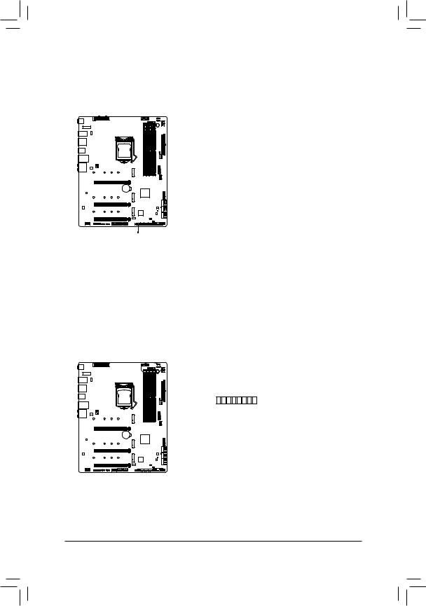
Quick Button
This motherboard has 2 quick buttons: power button and reset button. The power button and reset button allow users to quickly turn on/off or reset the computer in an open-case environment when they want to change hardware components or conduct hardware testing.


 PW_SW
PW_SW
PW_SW: Power Button
RST_SW: Reset Button
RST_SW
Voltage Measurement Points
Use a multimeter to measure the following motherboard voltages.
_PCH VAXGVCCIOVCCSAVCOREDDRVTTCOREDDRVPPVDDR
+ + + + + + + +
Hardware Installation |
- 24 - |
1-9 Internal Connectors
4 |
1 |
1 |
6 |
3 |
8 |
9 |
||||||||
|
|
|
|
|
|
|
|
|
|
|
|
|
|
|
|
|
|
|
|
|
|
|
|
|
|
|
|
|
|
|
|
|
|
|
|
|
|
|
|
|
|
|
|
|
|
|
|
|
|
|
|
|
|
|
|
|
|
|
|
7 |
2 |
5 |
4
|
16 |
12 |
15 |
|
|
|
21 |
|
19 |
12 |
11 |
|
|
12 |
7 |
|
|
|
20 |
14 |
8 |
9 |
18 |
17 |
10 |
4 |
5 |
13 |
1) |
ATX_12V_2X4_1/ATX_12V_2X4_2 |
12) |
M2P_SB/M2A_CPU/M2M_SB |
2) |
ATX |
13) |
F_PANEL |
3) |
CPU_FAN |
14) |
F_AUDIO |
4) |
SYS_FAN1/2/3/4 |
15) |
F_U32C |
5) |
SYS_FAN5_PUMP/SYS_FAN6_PUMP |
16) |
F_U32 |
6) |
CPU_OPT |
17) |
F_USB1/F_USB2 |
7) |
EC_TEMP1/EC_TEMP2 |
18) |
SPI_TPM |
8) |
D_LED1/D_LED2 |
19) |
THB_C1/THB_C2 |
9) |
LED_C1/LED_C2 |
20) |
CLR_CMOS |
10) |
NOISE_SENSOR |
21) |
BAT |
11) |
SATA3 0/1/2/3/4/5 |
|
|
Read the following guidelines before connecting external devices:
•First make sure your devices are compliant with the connectors you wish to connect.
•Before installing the devices, be sure to turn off the devices and your computer. Unplug the power cord from the power outlet to prevent damage to the devices.
•After installing the device and before turning on the computer, make sure the device cable has been securely attached to the connector on the motherboard.
- 25 - |
Hardware Installation |
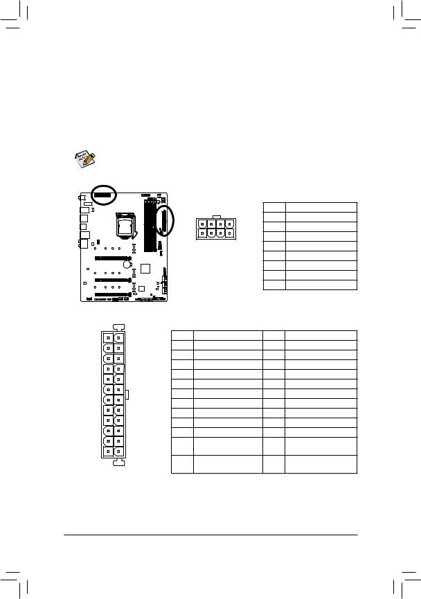
1/2)ATX_12V_2X4_1/ATX_12V_2X4_2/ATX(2x412VPowerConnectorsand2x12MainPower
Connector)
With the use of the power connector, the power supply can supply enough stable power to all the components on the motherboard. Before connecting the power connector, first make sure the power supply is turned off and all devices are properly installed. The power connector possesses a foolproof design. Connect the power supply cable to the power connector in the correct orientation.
The 12V power connector mainly supplies power to the CPU. If the 12V power connector is not connected, the computer will not start.
To meet expansion requirements, it is recommended that a power supply that can withstand high power consumption be used (500W or greater). If a power supply is used that does not provide the required power, the result can lead to an unstable or unbootable system.
|
|
|
|
ATX_12V_2X4_1/ATX_12V_2X4_2: |
|
|
|
|
|
Pin No. |
Definition |
|
|
5 |
8 |
1 |
GND (Only for 2x4-pin 12V) |
|
|
2 |
GND (Only for 2x4-pin 12V) |
||
|
|
1 |
4 |
||
|
|
3 |
GND |
||
|
|
|
|
||
|
|
ATX_12V_2X4_1/ATX_12V_2X4_2 |
4 |
GND |
|
|
|
|
|
5 |
+12V (Only for 2x4-pin 12V) |
|
|
|
|
6 |
+12V (Only for 2x4-pin 12V) |
|
|
|
|
7 |
+12V |
|
|
|
|
8 |
+12V |
|
|
ATX: |
|
|
|
12 |
24 |
Pin No. |
Definition |
Pin No. |
Definition |
|
|
1 |
3.3V |
13 |
3.3V |
|
|
2 |
3.3V |
14 |
-12V |
|
|
3 |
GND |
15 |
GND |
|
|
4 |
+5V |
16 |
PS_ON (soft On/Off) |
|
|
5 |
GND |
17 |
GND |
|
|
6 |
+5V |
18 |
GND |
|
|
7 |
GND |
19 |
GND |
|
|
8 |
Power Good |
20 |
NC |
|
|
9 |
5VSB (stand by +5V) |
21 |
+5V |
|
|
10 |
+12V |
22 |
+5V |
|
|
11 |
+12V (Only for 2x12-pin |
23 |
+5V (Only for 2x12-pin ATX) |
1 |
13 |
|
ATX) |
|
|
|
|
12 |
3.3V (Only for 2x12-pin |
24 |
GND (Only for 2x12-pin ATX) |
|
ATX |
|
ATX) |
|
|
Hardware Installation |
- 26 - |
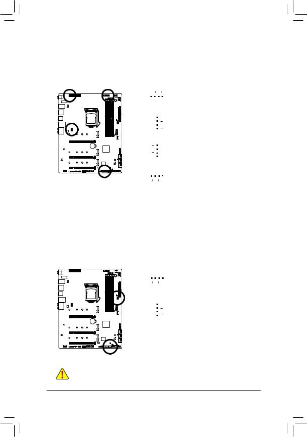
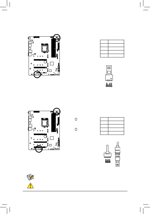
3/4) CPU_FAN/SYS_FAN1/2/3/4 (Fan Headers)
All fan headers on this motherboard are 4-pin. Most fan headers possess a foolproof insertion design. When connecting a fan cable, be sure to connect it in the correct orientation (the black connector wire is the ground wire). The speed control function requires the use of a fan with fan speed control design. For optimum heat dissipation, it is recommended that a system fan be installed inside the chassis.
|
|
|
|
|
|
|
1 |
|
|
|
|
|
|
|
|
|
|
|
|
|
|
|
|
|
|
|
Pin No. |
Definition |
|
|
|
|
|
|
|
|
|
||
|
CPU_FAN |
||||||||
|
1 |
GND |
|||||||
|
|
|
|
|
|
|
|
||
|
|
|
|
|
|
|
|
2 |
Voltage Speed Control |
|
|
|
|
|
|
|
|
3 |
Sense |
|
|
|
|
|
|
|
|
||
|
|
|
|
|
|
1 |
4 |
PWM Speed Control |
|
|
|
|
|
|
|
||||
SYS_FAN1 |
|
|
|||||||
|
|
||||||||
|
|
|
1 |
|
|
||||
|
|
|
|
|
|||||
|
|
||||||||
|
|
|
|
|
|
||||
|
|
|
|
|
|
||||
SYS_FAN2 |
|
|
|||||||
1 |
|
|
|
|
|
|
|
|
|
|
|
|
|
|
|
|
|
|
|
|
|
|
|
|
|
|
|
|
|
|
|
|
|
|
|
|
|
||
SYS_FAN3/SYS_FAN4 |
|
|
|||||||
5)SYS_FAN5_PUMP/SYS_FAN6_PUMP (System Fan/Water Cooling Pump Headers)
The fan/pump headers are 4-pin. Most fan headers possess a foolproof insertion design. When connecting a fan cable, be sure to connect it in the correct orientation (the black connector wire is the ground wire). The speed control function requires the use of a fan with fan speed control design. For optimum heat dissipation, it is recommended that a system fan be installed inside the chassis. The header also provides speed control for a water cooling pump, refer to Chapter 2, "BIOS Setup," "Settings\Smart Fan 5," for more information.
1 |
|
|
|
|
|
|
Pin No. |
Definition |
|
|
|
|
|
|
|
||||
|
|
|
|
|
|
1 |
GND |
||
|
|
|
|
|
|
|
|||
SYS_FAN5_PUMP |
|||||||||
2 |
Voltage Speed Control |
||||||||
|
|
|
|
|
|
|
|||
|
|
|
|
|
|
|
3 |
Sense |
|
|
|
|
|
|
1 |
4 |
PWM Speed Control |
||
|
|
|
|
|
|||||
|
|
|
|
|
|
|
|||
|
|
|
|
|
|
|
|||
SYS_FAN6_PUMP |
|
|
|||||||
•Be sure to connect fan cables to the fan headers to prevent your CPU and system from overheating. Overheating may result in damage to the CPU or the system may hang.
•Thesefanheadersarenotconfigurationjumperblocks.Donotplaceajumpercapontheheaders.
- 27 - |
Hardware Installation |
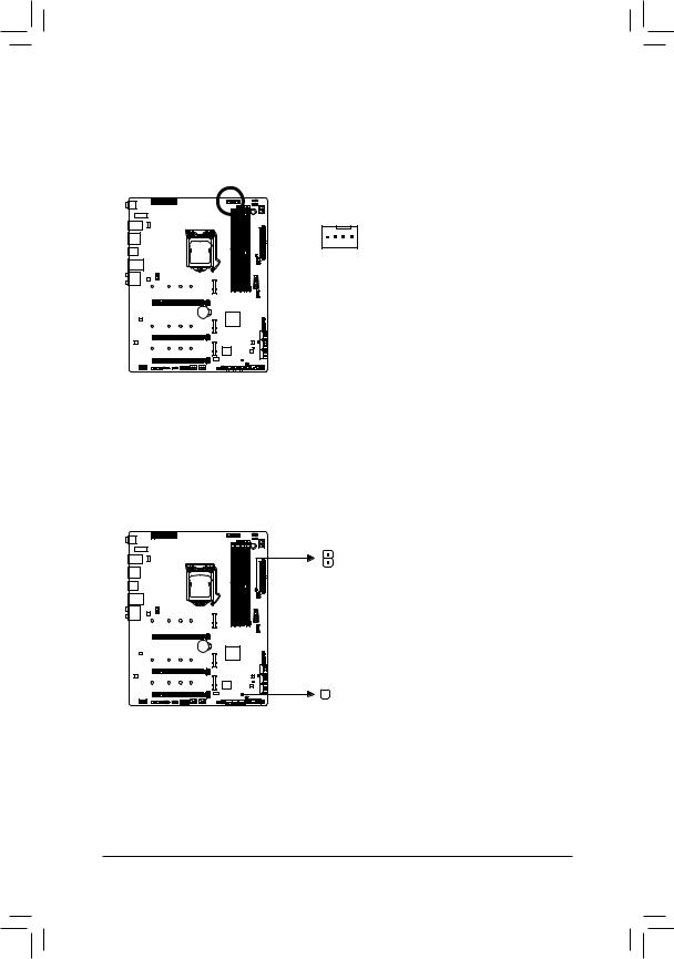
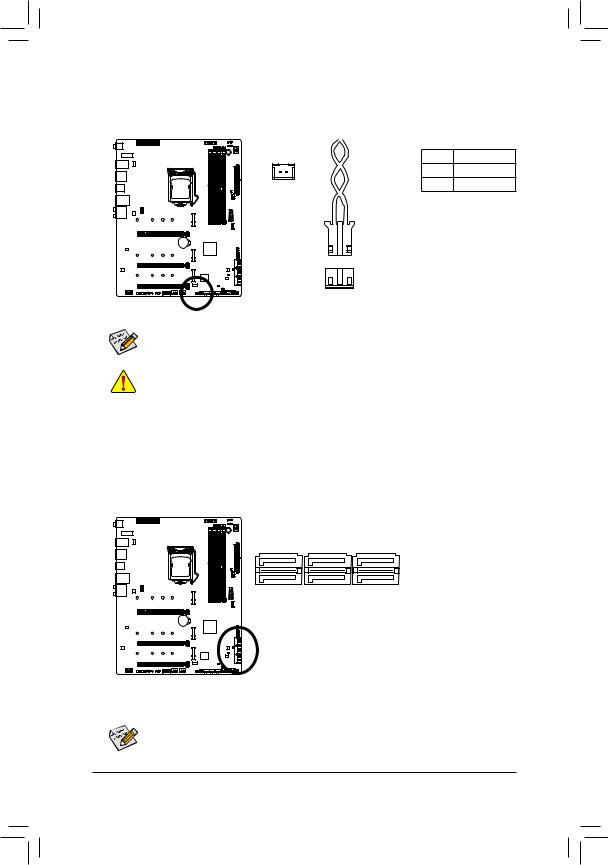
6)CPU_OPT (Water Cooling CPU Fan Header)
The fan header is 4-pin and possesses a foolproof insertion design. Most fan headers possess a foolproof insertion design. When connecting a fan cable, be sure to connect it in the correct orientation (the black connector wire is the ground wire). The speed control function requires the use of a fan with fan speed control design.
|
Pin No. |
Definition |
|
1 |
1 |
GND |
|
2 |
Voltage Speed Control |
||
|
|||
|
3 |
Sense |
|
|
4 |
PWM Speed Control |
7)EC_TEMP1/EC_TEMP2 (Temperature Sensor Headers)
Connect the thermistor cables to the headers for temperature detection.
EC_TEMP1 |
Pin No. |
Definition |
1 |
1 |
SENSOR IN |
|
2 |
GND |
1

 EC_TEMP2
Hardware Installation |
- 28 - |
8)D_LED1/D_LED2 (Addressable LED Strip Headers)
The headers can be used to connect a standard 5050 addressable LED strip, with maximum power rating of 5A (5V) and maximum number of 1000 LEDs.
1 

 D_LED1


 1
1
D_LED2


 Connect your addressable LED strip to the header. The power pin (marked with a triangle on the plug) of the LED strip must be connected to Pin 1 of
the addressable LED strip header. Incorrect connection may lead to the damage of the LED strip.
Pin No. |
Definition |
1 |
V (5V) |
2 |
D |
3 |
No Pin |
4 |
G |
Addressable LED
Strip
1
9)LED_C1/LED_C2 (RGB LED Strip Headers)
The headers can be used to connect a standard 5050 RGB LED strip (12V/G/R/B), with maximum power rating of 2A (12V) and maximum length of 2m.
1 


 LED_C1


 1
1
LED_C2
Connect one end of the RGB LED strip
extension cable to the header and the


 other end to your RGB LED strip. The black wire (marked with a triangle on the plug) of the extension cable must be connected to Pin 1 (12V) of
this header. The 12V pin (marked with an arrow) on the other end of the extension cable must be lined up with the 12V of the LED strip. Be careful with the connection orientation of the LED strip; incorrect connection may lead to the damage of the LED strip.
Pin No. |
Definition |
1 |
12V |
2 |
G |
3 |
R |
4 |
B |
G12V |
R |
B |
VG12 |
R |
B |
RGB LED
Strip
1
12V
 For how to turn on/off the lights of the LED strip, refer to the instructions on in Chapter 5, "Unique
Features," "APP Center\RGB Fusion."
Before installing the devices, be sure to turn off the devices and your computer. Unplug the power cord from the power outlet to prevent damage to the devices.
- 29 - |
Hardware Installation |
10)NOISE_SENSOR (Noise Detection Header)
This header can be used to connect a noise detection cable to detect the noise inside the case.
|
Pin No. |
Definition |
1 |
1 |
Noise Detection |
|
2 |
GND |
|
Noise Detection |
|
|
Cable |
|
|
1 |
|
For more information on the noise detection function, refer to the instructions in Chapter 5, "Unique Features," "APP Center\System Information Viewer"
Before connecting the cable to the header, make sure to remove the jumper cap; re-place the jumper cap if the header is not in use.
11)SATA3 0/1/2/3/4/5 (SATA 6Gb/s Connectors)
The SATA connectors conform to SATA 6Gb/s standard and are compatible with SATA 3Gb/s and SATA 1.5Gb/s standard. Each SATA connector supports a single SATA device. The Intel® Chipset supports RAID 0,
RAID 1, RAID 5, and RAID 10. Refer to Chapter 3, "Configuring a RAID Set," for instructions on configuring a RAID array.
|
|
|
|
|
Pin No. |
Definition |
|
|
|
|
|
|
1 |
GND |
|
7 |
|
|
1 |
2 |
TXP |
||
7 |
|
|
1 |
3 |
TXN |
||
|
|
|
|
|
4 |
GND |
|
|
5 |
3 |
1 |
|
|
|
|
SATA3 |
5 |
RXN |
|||||
4 |
2 |
0 |
|
||||
|
|
6 |
RXP |
||||
|
|
|
|
|
|||
|
|
|
|
|
7 |
GND |
|
To enable hot-plugging for the SATA ports, refer to Chapter 2, "BIOS Setup," "Settings\IO Ports\
SATAAnd RST Configuration," for more information.
Hardware Installation |
- 30 - |
Loading...