

Page 1

Installation Flusher disinfector S-406
INSTALLATION
9904
Flusher
disinfector
S-406
Serial No. 203.238 -
4996959-01
0301
1
Produced: 1998
Page 2

Flusher disinfector S-406 Installation
Contents
Safety rules _______________________________________________3
General safety rules _______________________________________ 3
Power cut-off device ______________________________________3
Caution symbols _________________________________________3
Installation ________________________________________________ 4
Free-standing position _____________________________________ 4
Fixation in wall __________________________________________4
Connection of electricity, water, drain, and possibly steam ________6
Goods arrangement chart __________________________________ 7
Detergent container _______________________________________8
Settings and functional check ________________________________ 9
Checking and changing preset parameters _____________________ 9
Setting the amount of cleaning and deliming agents on
pumps by means of adjusting screw _________________________10
Checking and adjusting the door turning mechanism ____________11
Final inspection _________________________________________12
9904
2
Page 3

Installation Flusher disinfector S-406
Safety rules
This machine is designed with a number of integrated safety devices. To avoid
personal injury it is essential that the safety devices are not bypassed or in any
other way put out of action.
General safety rules
• The machine should be connected in accordance with the installation
instructions.
• The machine may not by used by juveniles.
• Installation and servicing should be carried out by staff with experience of
this machine.
• The lid lock of the machine may not be bypassed under any circumstances.
• Leakage in the system, eg, due to worn lid gasket, must be repaired
immediately.
• Personnel concerned must study valid handbooks and service manuals prior to
any repairs or service work.
• The machine may not be sprayed with water.
• Caution must be observed when using corrosive detergents.
• Safety precautions must be observed when using hot water or steam.
Power cut-off device
The machine must always be provided with a separate power cut-off device in
the power supply line, easily accessible on the wall.
Caution symbols
This manual contains certain warnings, instructions and advice of such
importance that they are particularly emphasized. The configuration and use of
the appertaining symbols are as follows:
This symbol indicates a warning in text included in the manual.
Such warnings refer to hazards that can result in more or less
serious injury and in some cases fatal injury.
It is also used in warnings to avoid damage to the machine.
9904
3
Page 4

Flusher disinfector S-406 Installation
Installation
The disinfector may be placed in a free-standing position on four legs or mounted
on a wall in a special wall bracket.
To facilitate cleaning, a lateral distance of 100 mm to an adjacent wall or other
equipment is recommended. If the disinfector is installed next to a sink unit or
worktop, a lateral distance of 40 mm is recommended.
Wall-mounted models have a transport stay which should be removed.
Free-standing position
Screw the legs securely into the four corners of the support frame. Adjust with the
adjusting screws until the disinfector stands level and firm.
V060
Adjusting
screw
Leg
Fixation in wall
V116
Fig. 1. Fitting the support legs
• Fix the disinfector on the wall bracket supplied with the machine. If the wall
does not provide good support, use a wall fixture or support legs (both of
which can be ordered from Växjö Rostfritt). Ensure that the machine is in
level.
N.B.
If a wall fixture is used, this must be put into position when the
wall is being built up.
• Drill holes for the securing screws for the wall bracket as per figure 2.
235,5
179,5
235,5
179,5
350
Wall fixture
4685140-00
900
Wall bracket
9904
4
470
806
Wall
V061
Fig. 2. Hole pattern for wall bracket.
Page 5
Installation Flusher disinfector S-406
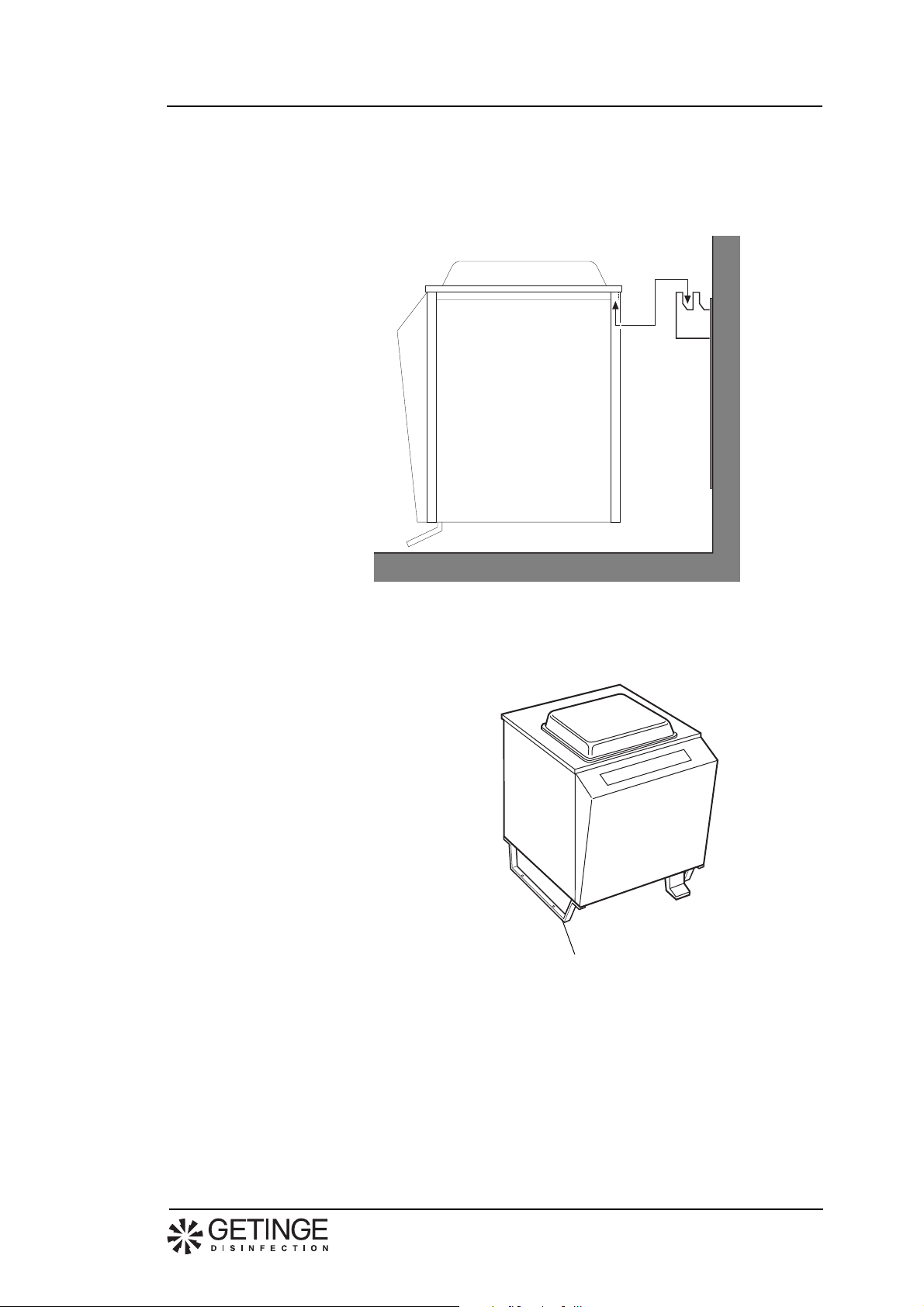
• If support legs are to be used: remove the transport stay and attach the legs
before fixing the disinfector in position.
• Make sure that the disinfector hooks properly into the bracket when it is
mounted on the wall fitting.
Fig 3. Mounting the wall bracket.
• Remove the transport stays.
V300
V644
Transport stay
9904
5
Page 6

Flusher disinfector S-406 Installation
Connection of electricity, water, drain, and possibly steam
May only be performed by authorized personnel.
• The electrical installation must include a cut-off device in the power supply
line to the machine to facilitate maintenance and servicing. The device shall
be located within easy reach on the wall.
• The terminals for electric installation are located under the cover of the
terminal block.
• Connect the disinfector to protective earth and to the voltage supply stated on
the type data plate. Check that the correct fuse is fitted. The recommended
fuse value is stated on the type plate.
• The mounting bracket for the terminal box can be unscrewed and pulled
forward to facilitate installation.
Electrical
connection
V116
Mounting
bracket
V296
Fig. 4. Electrical connection (see electric circuit diagram in Service
instructions).
• To prevent clogging of filters and valves, flush the water pipes clean, and any
steam pipes too, that are to be connected to the machine.
• Connect the disinfector to the cold and hot water supply, and to steam supply
if used. The water and steam connections must conform to the following
requirements:
Connection (mm) Pressure (kPa) Flow (l/s) Consumption (l/process)
Normal Glassware
Cold water 15 50-500 0,2 15 8
Hot water 15 50-500 0,2 18 16
Steam 15 60-300 0,5 kg/process
9904
6
• Drill out the steam jets if necesssary as per the table below:
Steam pressure
kPa
Hole diameters
mm
60-80 80-125 125-200 200-250 250-300
5 4 3.5 3 2,5
• Teflon tape is recommended for sealing the connections.
Page 7

Installation Flusher disinfector S-406
590
295
900
V313
250
150
180
Hot water
Cold water
255 255
180
Fig. 5. Connection of water and steam supply.
Electricity
Steam
• Connect the disinfector to drain outlet. The drain outlet can be connected
either to the rear or downwards as shown in figure 6. Pipe diameter: 110 mm.
600
470
V314
110
Fig. 6. Connection of drain outlet.
Goods arrangement chart
Place the notice with user’s instruction on the wall above the disinfector. Make
sure that the lid does not obscure the chart.
9904
7
Page 8

Flusher disinfector S-406 Installation
Detergent container
• For machines fitted with a dosing system, a tray is provided for the detergent
container, which is fitted on the left-hand or right-hand side of the disinfector
(Fig. 7).
• Fit the tray with the screws in the two cage nuts.
Wear protective gloves. The media in the cans can be corrosive.
• The container may also be placed on the floor or on the lower shelf of an
adjacent sink unit, up to a distance of about 70 cm from the disinfector. The
bottom of the container should not be higher than the lower edge of the side
plates on the disinfector.
• The suction line that is inserted into the detergent container is placed inside
the front panel on delivery. Som option kan Spoldesinfektorn förses med
nivågivare för medel.
Cage nut
Shelf
Screw
V119
Fig. 7. Tray for detergent container.
9904
8
Page 9

Installation Flusher disinfector S-406
Settings and functional check
• Check to make sure that the disinfector is connected to the correct voltage as
indicated on the type data plate.
• Open the water valves, and steam valve if relevant, and turn on the main
switch.
To adapt the machine to the prevailing operating conditions, a number of
parameters must be checked and possibly reset when installing.
The following parameters are to be checked when installing:
• Amount of cleaning agent, see page 10.
• Amount of deliming agent, see page 10.
Checking and changing preset parameters
V310
12 3 45
To check the parameters for the above items, you should enter the service
program as follows:
• Simultaneously press 4 and 5 for 10 seconds.
The machine is then reset to the Service mode (see also under the heading
’Service program’). The push buttons 1 - 5 will have the following
functions:
1 Up 4 Abort
2 Down 5 Completed
3 ON/OFF
• Press 1 and 2 until you arrive at the desired line number as shown in
the table below:
Parameter Line number Basic setting Setting range
Amount of cleaning agent * 42 25 0 - 99
Amount of deliming agent * 48 13 0 - 99
* See further under the heading Setting the amount of detergent and descaling compound.
• Press 5 to enter the line. You can then read the set value and check it against
the table above.
9904
N.B.
To change the contents of a line you must first key in your authority
code (1992) on line 00.
• Use 1 and 2 to change the contents of a line to the desired value as per
the above table.
9
Page 10

Flusher disinfector S-406 Installation
• Press 5 when you have finished. The display window will then go ’OFF’
for a short period (the new value is stored in the machine memory) and then
the new value will be displayed with a steady light.
If you change your mind before pressing ’Completed’, you can press4. The
old value will then be reset again.
• Press 5 once again to quit the line and enter the line number. Go to the
next line that is to be changed.
• Press 4 for three seconds to quit the service program.
The machine is now ready for operation.
Setting the amount of cleaning and deliming agents on pumps by means of adjusting screw
The disinfector may be supplied with three different dosage systems: two for
detergent dosage and one for descaling compound. For descaling and spray
dosage the amount of compound can be set in the service program (see
Illustration 8).
May only be performed by authorized personnel.
This machine is connected to mains power supply and some
components are live.
Set by the service program
V071
Detergent pump
50 ml
V304
Detergent pump
(spray)
40 ml
Deliming pump
6 - 10 dH° 1,5 ml
10 - 15 dH° 3,0 ml
15 - 20 dH° 4,5 ml
V583
Fig. 8. Dosage pumps
• Measure out 100 ml of detergent into a measuring glass. Check that the
suction pipe and pump are full of detergent before carrying out the check.
• Insert the suction pipe into the measuring glass and run a washing program.
Remove the suction pipe and read off consumption. Adjust if necessary in the
service program and repeat measurement until the amount is correct
according to manufacturer’s recommendations.
9904
10
Page 11

Installation Flusher disinfector S-406
Checking and adjusting the door turning mechanism
May only be performed by authorized personnel.
This machine is connected to mains power supply and some
components are live.
If a program starts and the lid is obstructed by an object between the lid and the
top of the disinfector, the lid shall open again. The limit for this safety
precaution is between 6 and 12 mm as shown in figure 9.
Use the accompanying spacer bar to check this function.
• Stand the bar on edge (so that it is 12 mm high).
• Insert it between the top of the machine and the lid.
• Close the lid.
The lid must change direction and open again.
• Then turn the bar so that it is 6 mm high.
• Check to ensure that the lid closes.
Adjustment of the lid reversing function is described in the Service instructions.
V601
Fig. 9. Closing the lid.
6-12 mm
9904
11
Page 12

Flusher disinfector S-406 Installation
Final inspection
• If the machine has dosing of cleaning agent: Press S and check to make
sure the lamp in the push button lights.
• Check to make sure the incoming hot water has the correct temperature. It
should be between 45 and 60°C.
• Start the ’Normal’ program with empty machine and check that:
- The PROCESS IN OPERATION lamp is ON.
- The temperature rises continuously until its cooling phase begins.
- Any pause for heating is not longer than about 10 minutes (applies to
apparatus connected to steam and apparatus with steam generator).
- The final temperature is higher than 90°C.
- The PROCESS COMPLETE lamp lights when the program is over.
Fig. 10. Indicating lamps
L M K
Process in operation
• If the machine has a system for cleaning or deliming agent, or both:
Pour a sufficient amount of agent into a measuring glass. Make sure that the
suction hose is full of agent. Start a ’normal’ program and check that the
disinfector uses the correct amount. For cleaning agent, the amount per
program is normally about 30 ml, and for deliming agent about 1,5 to 4,5 ml
(follow the supplier’s recommendations).
N.B.
When taking the reading, the suction pipe should not be in the
measuring glass.
• Check that there are no leaks. Tighten if necessary.
Process completed
9904
12
Page 13

Installation Flusher disinfector S-406
Technical data
Weight 70 kg
Width 590 mm
Depth600 mm
Height 900 mm
Ambient requirements:
Relative humidity maximum 80% at 31°C
Room temperature 5 - 40 °C
Cold water
Connection 15 (1/2") mm
Pressure 50-500 kPa
Flow 0,2 l/s
Consumption 13 l/process
Hot water
Temperature 45-60 °C
Connection 15 (1/2") mm
Pressure 50-500 kPa
Flow 0,2 l/s
Consumption 22 l/process
Steam (V version only)
Connection 15 (1/2") mm
Pressure 60-300 kPa
Consumption 0,3 kg/process
Drain outlet dia. 110 mm
Max. external temperature 50 °C
Noise level ca 59 dB(A)
Power
Model Electrical connection Fuse requirement
L1 230 V, 1N+PE 50 Hz (TN) 1x16 A 2,94 kW
L2 230 V, 3+PE 50 Hz 3x16 A 3,91 kW
L3 400 V, 3N+PE 50 Hz (TN) 3x10 A 3,91 kW
L5 240 V, 2+PE 60 Hz (TN) 2x15 A 3,29 kW
L6 240 V, 3N+PE 60 Hz (TN) 3x15 A 4,26 kW
L9 208 V, 2+PE 60 Hz (TN) 2x15 A 3,29 kW
L10 208 V, 3N+PE 60 Hz (TN) 3x15 A 4,26 kW
L14 200 V, 2+PE 50 Hz (TN) 2x16 A 2,94 kW
L15 200 V, 3+PE 50 Hz (TN) 3x16 A 2,94 kW
L18 200 V, 2+PE 60 Hz (TN) 2x16 A 3,29 kW
L19 200 V, 3+PE 60 Hz (TN) 3x16 A 3,29 kW
L22 230 V, 1N+PE 60 Hz (TN) 1x16 A 3,29 kW
L24 400 V, 3N+PE 60 Hz (TN )3x10 A 4,26 kW
V2 230 V, 1N+PE 50Hz (TN) 1x10 A 1,01 kW
V3 240 V, 2+PE 60 Hz (TN) 2x15 A 1,36 kW
V4 208 V, 2+PE 60 Hz (TN) 2x15 A 1,36 kW
9904
V7 230 V, 1N+PE 60Hz (TN) 1x10 A 1,36 kW
13
Page 14

Flusher disinfector S-406 Installation
Diameter of nozzle orifice at various steam pressures
If no steam pressure is specified, the disinfector nozzle is delivered with an
orifice diameter of 1.8 mm. If the pressure used is less than 300 kPa, the nozzle
orifice should be made larger as shown in the table below.
Steam pressure
kPa
Orifice diameter
60-80 80-125 125-200 200-250 250-300
5 4 3.5 3 2,5
9904
14
Page 15

Installation Flusher disinfector S-406
9904
15
Page 16

Page 17

Page 18

Page 19

Page 20

Page 21

Page 22

Page 23

Page 24

This product is manufactur ed b y:
GETINGE DISINFECTION AB, Ljungadalsgatan 11, Box 1505, 351 15 Växjö, Sweden
 Loading...