

Page 1

USER MANUAL
350545 Rev. F
MP–129 Series
Water-Saver
Page 2

Page 3

USER MANUAL
350545 Rev. F
MP–129 SERIES
WATER-SAVER
Getinge USA, Inc.
1777 East Henrietta Road
Rochester, New York 14623-3133 USA
Phone: (800) 950-9912
Facsimile: (800) 950-2570
Page 4
USER MANUAL 350545
Rev. A (9/09/94) Graphics revised, pgs 11 & 22
Rev. B (11/22/96) General revision; combined with Parts Catalog (350575)
Rev. C (01/31/97) Company name changed to Getinge/Castle, Inc.
Rev. D (10/26/99) Redesign to fit Series x00 sterilizers
Rev. E (10/05/01) Update to reflect design changes—BOMs removed
Rev. F (4/30/03) General Revision; MP-129F added
DESCRIPTION OF SYMBOLS & NOTES IN MANUAL
The following symbols with related notes appear in this manual.
DANGER
WARNING
CAUTION
NOTE
NOTES
“Danger” notes alert the user to the possibility of serious injury or death.
“Warning” notes alert the user to the possibility of personal injury.
“Caution” notes alert the user to the possibility of damage to the equipment.
“Notes” alert the user to pertinent facts and conditions.
• This manual contains proprietary information of Getinge USA, Inc. It shall
not be reproduced in whole or in part without the written permission of
Getinge USA, Inc.
• This manual is intended for qualified technicians with specialized training.
If you require additional help, contact the company service representative.
is a registered trademark.
Copyright © 2003 by Getinge USA, Inc.
ii
Page 5

Section 1 Introduction
GENERAL DESCRIPTION. . . . . . . . . . . . . . . . . . . . . . . . . 1–1
TECHNICAL DATA. . . . . . . . . . . . . . . . . . . . . . . . . . . . . . . 1–4
THEORY OF OPERATION . . . . . . . . . . . . . . . . . . . . . . . . 1–5
BYPASS SWITCH . . . . . . . . . . . . . . . . . . . . . . . . . . . . . . . 1–8
MANUAL DRAIN VALVE . . . . . . . . . . . . . . . . . . . . . . . . . . 1–8
Section 2 MP-129 Installation
PACKAGE CONTENTS . . . . . . . . . . . . . . . . . . . . . . . . . . . 2–2
MP-129 INSTALLATION SEQUENCE. . . . . . . . . . . . . . . . 2–4
LOCATING, MOUNTING, AND ANCHORING. . . . . . . . . . 2–5
CONNECTING THE PIPING COMPONENTS . . . . . . . . . . 2–6
CONNECTING THE ELECTRICAL CABLES
CONNECTING THE ELECTRICAL CABLES
Table of Contents
MP-129 Water-Saver . . . . . . . . . . . . . . . . . . . . . . . . . .1–2
MP-129F Water-Saver . . . . . . . . . . . . . . . . . . . . . . . . .1–3
MP-129 Water-Saver . . . . . . . . . . . . . . . . . . . . . . . . . . 1–5
MP-129F Water-Saver . . . . . . . . . . . . . . . . . . . . . . . . .1–6
All Models . . . . . . . . . . . . . . . . . . . . . . . . . . . . . . . . . . .1–7
MP-129 . . . . . . . . . . . . . . . . . . . . . . . . . . . . . . . . . . . . 1–8
MP-129F . . . . . . . . . . . . . . . . . . . . . . . . . . . . . . . . . . . 1–8
MP-129A . . . . . . . . . . . . . . . . . . . . . . . . . . . . . . . . . . . 2–2
MP-129B . . . . . . . . . . . . . . . . . . . . . . . . . . . . . . . . . . . 2–2
MP-129C . . . . . . . . . . . . . . . . . . . . . . . . . . . . . . . . . . . 2–2
MP-129D . . . . . . . . . . . . . . . . . . . . . . . . . . . . . . . . . . . 2–2
220V Conversion Packages . . . . . . . . . . . . . . . . . . . . . 2–3
Location . . . . . . . . . . . . . . . . . . . . . . . . . . . . . . . . . . . . 2–5
Mounting and Anchoring . . . . . . . . . . . . . . . . . . . . . . . 2–5
Water-Saver I/F Box . . . . . . . . . . . . . . . . . . . . . . . . . . 2–5
Pressure Switch 1PS . . . . . . . . . . . . . . . . . . . . . . . . . . 2–6
Solenoid Valve 20SV and Check Valve 9CV . . . . . . . . 2–6
Cold Water Supply . . . . . . . . . . . . . . . . . . . . . . . . . . . . 2–7
Overflow Drain . . . . . . . . . . . . . . . . . . . . . . . . . . . . . . . 2–7
(MP-129 A & B) . . . . . . . . . . . . . . . . . . . . . . . . . . . . . . 2–8
Pump Motor 2–9
Pressure Switch. . . . . . . . . . . . . . . . . . . . . . . . . . . . . . 2–9
Solenoid Valves . . . . . . . . . . . . . . . . . . . . . . . . . . . . . . 2–9
Water-Saver I/F Box . . . . . . . . . . . . . . . . . . . . . . . . . . 2–9
(MP-129 C & D) . . . . . . . . . . . . . . . . . . . . . . . . . . . . . 2–11
iii
Page 6

CHECKING THE ROTATION OF THE PUMP MOTOR . . 2–14
Section 3 MP-129F Installation
PACKAGE CONTENTS . . . . . . . . . . . . . . . . . . . . . . . . . . . 3–2
MP-129F INSTALLATION SEQUENCE . . . . . . . . . . . . . . . 3–3
LOCATING, MOUNTING, AND ANCHORING . . . . . . . . . . 3–4
CONNECTING THE PIPING . . . . . . . . . . . . . . . . . . . . . . . 3–5
CONNECTING THE ELECTRICAL CABLES . . . . . . . . . . 3–7
CHECKING THE ROTATION OF THE PUMP MOTOR . . . 3–9
CHECKING THE OVERLOAD RELAY. . . . . . . . . . . . . . . 3–10
Pump Motor Connection . . . . . . . . . . . . . . . . . . . . . . 2–12
Pressure Switch. . . . . . . . . . . . . . . . . . . . . . . . . . . . . 2–12
Solenoid Valves. . . . . . . . . . . . . . . . . . . . . . . . . . . . . 2–12
Motor Start Relay (11A). . . . . . . . . . . . . . . . . . . . . . . 2–13
MP-129F . . . . . . . . . . . . . . . . . . . . . . . . . . . . . . . . . . . 3–2
220V Conversion Package . . . . . . . . . . . . . . . . . . . . . 3–2
Location. . . . . . . . . . . . . . . . . . . . . . . . . . . . . . . . . . . . 3–4
Mounting and Anchoring . . . . . . . . . . . . . . . . . . . . . . . 3–4
Solenoid Valve 15SV and Check Valve 9CV . . . . . . . . 3–5
Cold Water Supply. . . . . . . . . . . . . . . . . . . . . . . . . . . . 3–5
Overflow Drain . . . . . . . . . . . . . . . . . . . . . . . . . . . . . . . 3–6
Pump Motor . . . . . . . . . . . . . . . . . . . . . . . . . . . . . . . . . 3–8
Water-Saver I/F Box . . . . . . . . . . . . . . . . . . . . . . . . . . 3–8
Solenoid Valve. . . . . . . . . . . . . . . . . . . . . . . . . . . . . . . 3–8
Section 4 Maintenance and Troubleshooting
PERIODIC MAINTENANCE SCHEDULE . . . . . . . . . . . . . 4–1
CLEANING AND SANITIZING THE TANK . . . . . . . . . . . . 4–2
TEMPERATURE SWITCH ADJUSTMENT . . . . . . . . . . . . 4–3
PRESSURE SWITCH ADJUSTMENT. . . . . . . . . . . . . . . . 4–4
100 and 200 Series . . . . . . . . . . . . . . . . . . . . . . . . . . . 4–4
M/C 3500 and 3600 . . . . . . . . . . . . . . . . . . . . . . . . . . . 4–5
M/C 4200 . . . . . . . . . . . . . . . . . . . . . . . . . . . . . . . . . . . 4–6
TROUBLESHOOTING. . . . . . . . . . . . . . . . . . . . . . . . . . . . 4–7
RECOMMENDED SPARE PARTS . . . . . . . . . . . . . . . . . . 4–8
MP-129 (A&B) . . . . . . . . . . . . . . . . . . . . . . . . . . . . . . . 4–8
MP-129 (C&D). . . . . . . . . . . . . . . . . . . . . . . . . . . . . . . 4–8
MP-129F . . . . . . . . . . . . . . . . . . . . . . . . . . . . . . . . . . . . 4–9
Ordering. . . . . . . . . . . . . . . . . . . . . . . . . . . . . . . . . . . . 4–9
Section 5 Reference Drawings
INTRODUCTION . . . . . . . . . . . . . . . . . . . . . . . . . . . . . . . . 5–1
iv
Page 7
GENERAL DESCRIPTION
Section 1 Introduction
The water-saver is an add-on system that incorporates a water ejector with
a pump and a water reservoir to recirculate the water that creates the
vacuum necessary for part of the sterilization cycle. The water-saver can
typically save 70% of the total water used during a cycle.
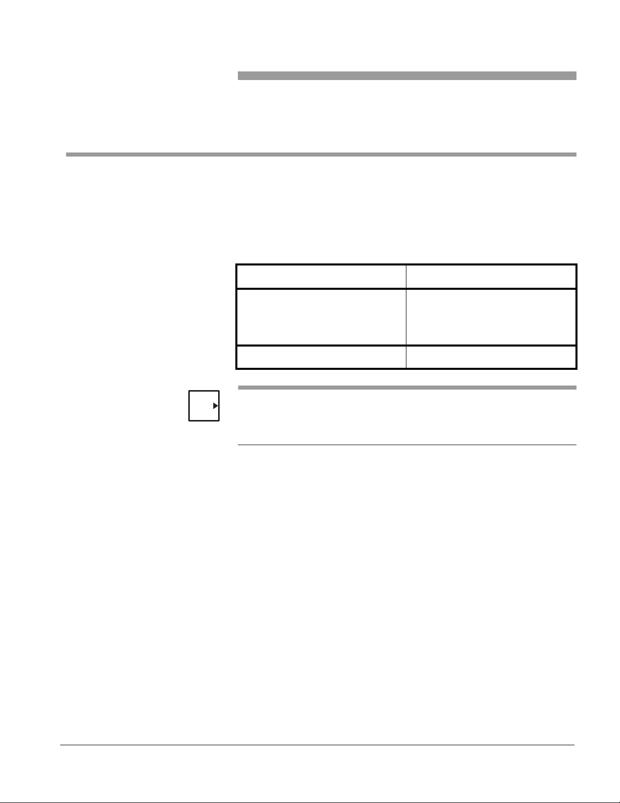
Compatible sterilizer models are listed in Table 1–1.
Table 1–1. Water-Saver Models
Water-Saver Model Sterilizer Model
NOTES
MP-129A
MP-129B
MP-129C
MP-129D
MP-129F 400/500, 700 and 800 Series
• In this manual, "MP-129 Water-Saver" refers to MP-129A, B, C, and D.
• The MP-129A can be installed on the 400/500 Series sterilizers, but the
MP129F is preferred because it does not require a pressure switch.
M/C 3500 and 100 Series (see Note)
M/C 3600 and 200 Series
M/C 4233 (42")
M/C 4233 (76")
350545 1–1
Page 8
Introduction
Click Here To View Parts List & Wiring Rev A thru E
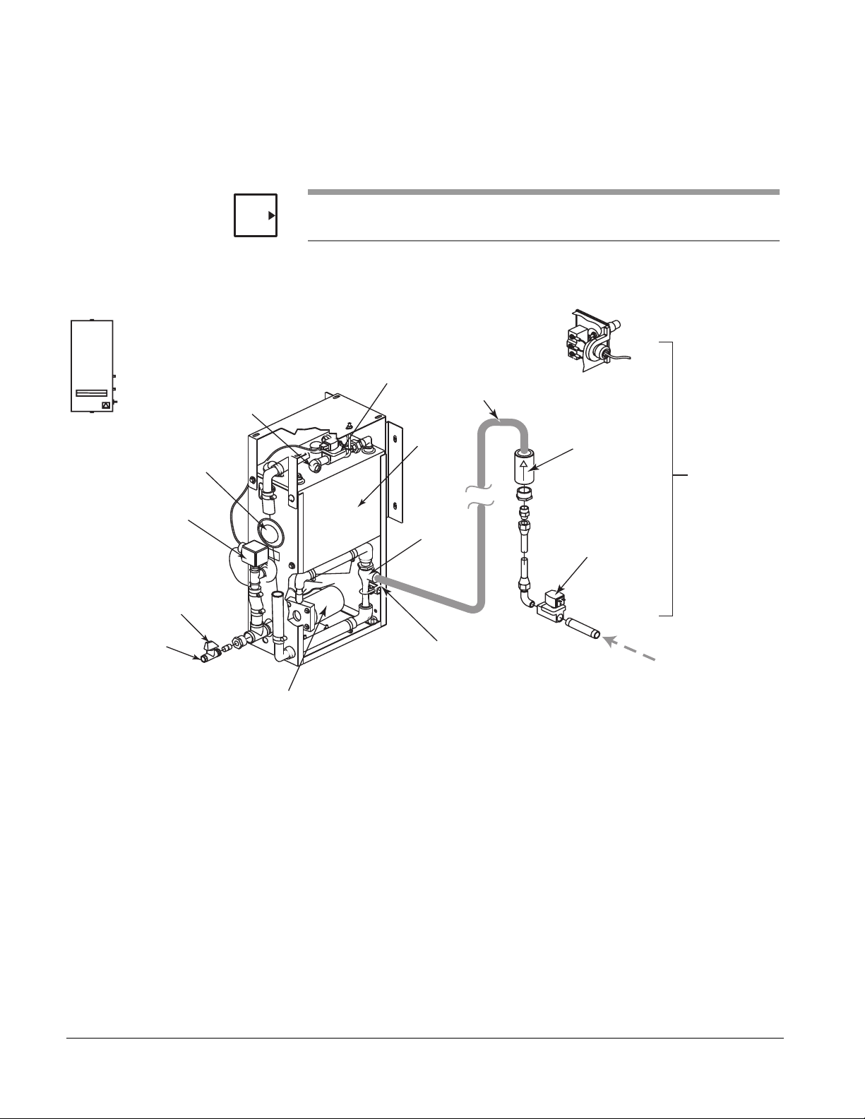
MP-129 Water-Saver The operation of the MP-129 Water-Saver (see Figure 1–1) is controlled by
an electromechanical pressure switch (1PS) that monitors the pressure in
the sterilizer chamber. See Theory of Operation — “MP-129 Water-Saver”
on page 1–5 for a detailed description.
Water-Saver
I/F Box
47A
Overflow
Drain Outlet
Temperature
Control Switch
1S
Manual
Drain Valve
NOTE
Water Supply
Inlet
Water-Saver I/F Box 47A can be mounted at any convenient location near the water-saver.
Figure 1–1. MP-129 WATER-SAVER PACKAGE
Water to Tank
Solenoid Valve
1SV
Copper Tubing
(by customer)
Reservoir
Ejector
Pressure
Switch 1PS
Check Valve
9CV
Parts Mounted
on Sterilizer
Solenoid Valve
20SV
Water Saver
Drain Outlet
Recirculating
Pump
Ejector
Vacuum Inlet
Exhaust from
Sterilizer
350545-AB
1–2
Page 9

MP-129 Series Water-Saver
Click Here To Open Parts List & Wiring Rev F
MP-129F Water-Saver The operation of the MP-129F Water-Saver (see Figure 1–2) is controlled by
the sterilizer software. See Theory of Operation — “MP-129F Water-Saver”
on page 1–6 for a detailed description.
Overflow
Drain Outlet
Temperature
Control Switch
1S
Manual
Drain Valve
NOTE
Water-Saver
I/F Box
11A
Water Supply
Inlet
Water-Saver I/F Box 11A is mounted on the water-saver unit. Water to
Ejector solenoid valve 6SV and Water-Saver ON solenoid valve 15SV are
connected directly to sterilizer Control Box 2A.
Figure 1–2. MP-129F WATER-SAVER PACKAGE
Water to Tank
Solenoid Valve
1SV
Reservoir
Ejector
Copper Tubing
(by customer)
Check Valve
Water-Saver ON
Solenoid Valve 15SV
9CV
Parts Mounted
on Sterilizer
Water Saver
Drain Outlet
Recirculating
Pump
Ejector
Vacuum Inlet
Exhaust from
Sterilizer
350545-AC
350545 1–3
Page 10

Introduction
TECHNICAL DATA
NOTE
The water-saver should not be used with a sterilizer with Sealing Flange—
for example, those installed in an area that may process Bio Hazard
material or Bio-contaminated waste. If installed in a sterilizer of this type, the
water-saver could become a breeding ground for bioburden, which would
then be constantly recirculated through the system. Additionally,
decontaminating the components would be difficult at best.
The dimensions and weight, utilities requirements, and electrical supply for
the water-saver are listed on installation drawing HS3472, included in the
water-saver package.
The capacity of the reservoir tank is approximately 6 gallons (22.7 liters).
1–4
Page 11
MP-129 Series Water-Saver
st
g
l
Click Here To View Parts List & Wiring Rev A thru E
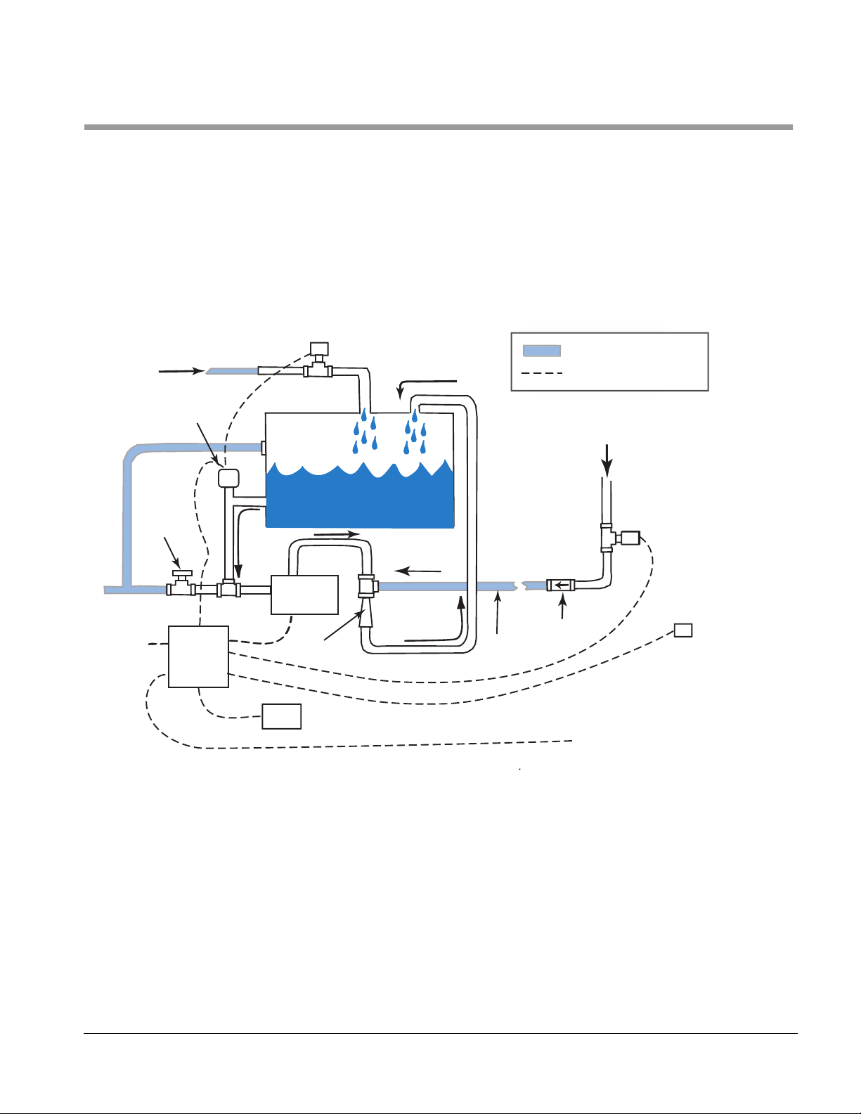
THEORY OF OPERATION
MP-129 Water-Saver Water-saver Pressure Switch 1PS determines whether the water-saver or
the standard ejector in the sterilizer provides the vacuum. While the
pressure in the sterilizer chamber is above 1 PSIG, Pressure Switch 1PS
selects the standard ejector. But when the sterilizer chamber pressure drops
to 1 PSIG or lower, Pressure Switch 1PS instead turns on the recirculating
pump to activate the ejector in the water-saver system.
Figure 1–3. MP-129 WATER-SAVER SYSTEM
1SV
Customer Pipin
Cold Water
Temperature
Switch
Electrica
Exhau
from Sterilizer
115 VAC
Manual
Drain
Valve
I/F Box
47A
1S
Water Saver ON
20SV
Pump
Water to Ejector
6SV
350545-AD
Ejector
Pressure Switch
1PS
Copper
Tubing
Check
Valve
Water to Ejector
Output from Sterilizer
350545 1–5
Page 12

Introduction
st
g
l
Click Here To Open Parts List & Wiring Rev F
MP-129F Water-Saver Pressure values are evaluated by the sterilizer software to determine
whether the water-saver or the standard ejector in the sterilizer provides the
vacuum. The water-saver configuration dipswitch (DS14 on the sterilizer’s
DISPSWITCHES menu) must be set to 1 in order for the water-saver to
operate. While the pressure in the chamber is above -5 psig for vacuum
cycles, or above atmospheric pressure for gravity cycles, the sterilizer
software selects the standard ejector. When below these values, the
software turns on the water saver.
Figure 1–4. MP-129F WATER-SAVER SYSTEM
1SV
Customer Pipin
Cold Water
Temperature
Switch
Electrica
Exhau
from Sterilizer
115 VAC
Manual
Drain
Valve
I/F Box
11A
1S
Pump
Ejector
Copper
Tubing
Water-Saver ON
15SV
Check
Valve
Water-Saver ON
Output DO14
from Sterilzer
350545-AE
1–6
Page 13

MP-129 Series Water-Saver
All Models Solenoid valve 6SV, which supplies water to activate the standard ejector, is
still active in the sterilizer piping system. However, 6SV is only energized
during negative pulses and during the purge above the water-saver pressure setpoint.
The cooler the water used for the ejector, the more efficiently the ejector
operates. To keep the water in the reservoir below 120°F (49°C), temperature control switch 1S controls the flow of cold water through solenoid valve
1SV.
When the water temperature rises above 115°F (46°C), temperature control
switch 1S signals solenoid valve 1SV to open, allowing cold water to enter
the reservoir and cool the stored water. Temperature control valve 1S continually monitors the water temperature within the reservoir. When the reservoir water cools (temperature is below 96°F [36°C]), temperature control
switch 1S outputs signals to solenoid valve 1SV and the solenoid valve
closes. This maintains the desired water temperature.
Any excess water, such as when cooling water is added to the reservoir,
drains through the overflow drain port.
When the pump motor turns on, it draws water from the bottom of the reservoir into the pump. The pump forces the water through the ejector and then
recirculates it to the reservoir. This creates the required vacuum.
350545 1–7
Page 14
Introduction
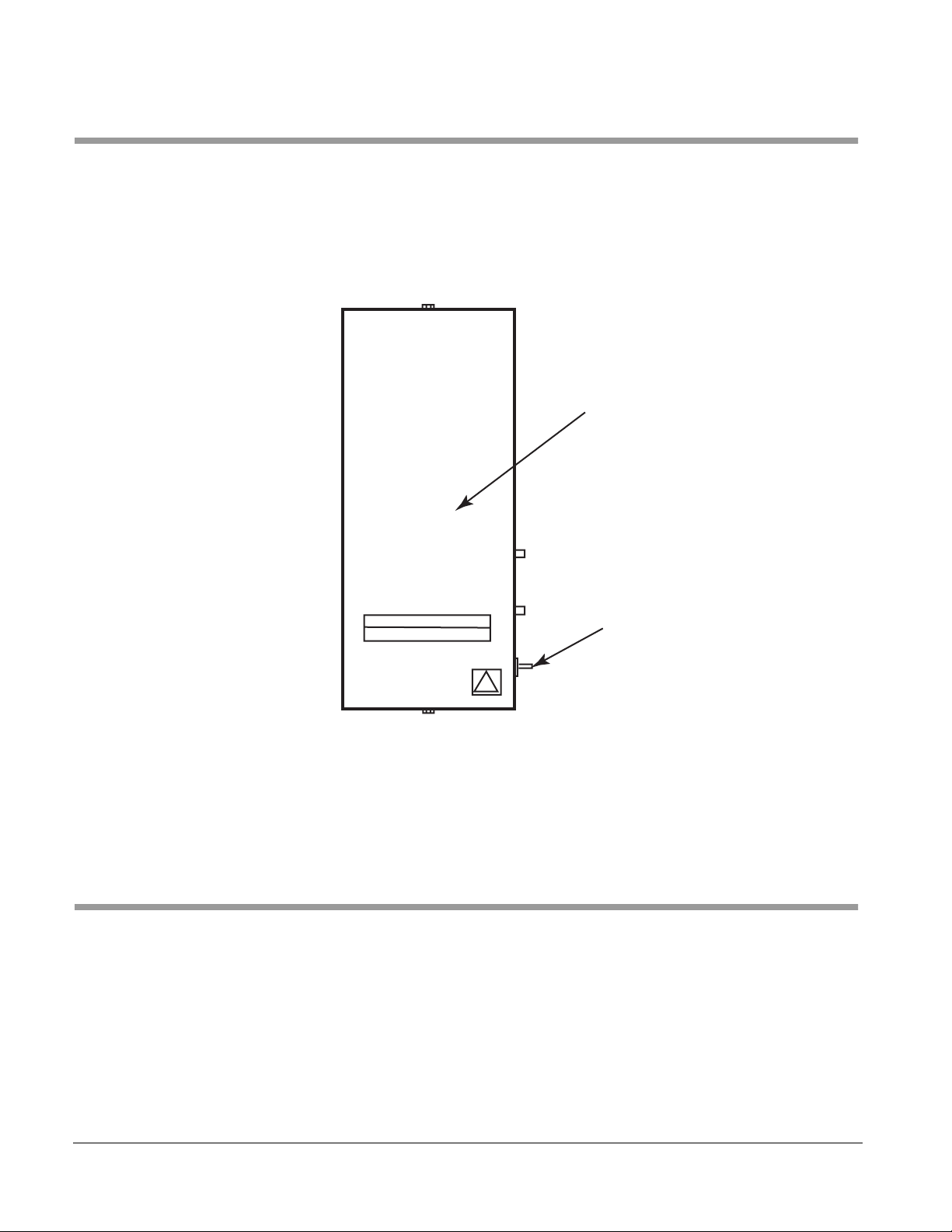
BYPASS SWITCH
MP-129 The toggle switch on Water-Saver I/F Box 47A permits hospital
maintenance or Getinge USA service personnel to switch off the watersaver as a vacuum source and use the sterilizer’s standard ejector with
external water supply.
Figure 1–5. BYPASS SWITCH (MP-129 Only)
Water Saver
I/F Box 41A
Bypass
Switch
MP-129F The water-saver can be turned off from the display panel on the sterilizer.
The Water Saver configuration switch (DS14) is located on the
DIPSWITCHES branch of the SERVICE menu tree. Refer to the sterilizer
Service Manual for instructions on how to navigate the menu tree.
MANUAL DRAIN VALVE
Located in the feed water line to the pump, this manual valve permits easy
draining of the water-saver reservoir when required.
1–8
Page 15
Section 2 MP-129 Installation
Follow the instructions in this user manual when installing an MP-129
Water-Saver to any of the following sterilizers:
• 100 and M/C 3500 Series (MP-129A)
• 200 and M/C 3600 Series (MP-129B)
• M/C 4233 (42") (MP-129C)
• M/C 4233 (76") (MP-129D)
CAUTION
NOTES
If you are installing a MP-129F Water-Saver to a 400/500, 700
or 800 Series sterilizer, follow the instructions in Section 3.
High-vacuum sterilizers (x33 or xx33 models) benefit most from the use of
the water-saver. However, the water-saver can be installed on any Getinge
USA sterilizer that uses a water ejector as its vacuum source.
Bills of Materials (BOMs) and drawings necessary for assembling this kit are
included with the parts.
• Use the BOMs as a checklist to verify receipt of all parts.
• Use the BOMs and the drawings to assemble the parts per these
instructions.
• Retain all BOMs and drawings with the unit for future reference
350545 2–1
Page 16

MP-129 Installation
Click Here To View Parts List & Wiring Rev A thru E
PACKAGE CONTENTS
MP-129A Assembly 61301602997 (Rev. C)
Item Description Part Number Qty
1 MANUAL(U)-WATER SAVER 350545
2 CASTLE,WATER SAVER SYS HS03472
3 WATER SAVER PKG,1.25ID,120V 531167
4 PIPING PKG,100/MC3500,WTR SVR 61301603246
5 SCH,PIPING,SPCL OPTION P1925
6 CONT PKG,WTR SVR,PACS/MC,120V 61301603222
7 DIAG,WIRING,WTR SVR,PACS/MC W1297
MP-129B Assembly 61301602998 (Rev. A)
Item Description Part Number Qty
1 MANUAL(U)-WATER SAVER 350545
2 CASTLE,WATER SAVER SYS HS03472
3 WATER SAVER PKG,1.25ID,120V 531167
4 PIPING PKG,233/MC3633,WTR SVR 61301603247
5 SCH,PIPING,SPCL OPTION P1925
6 CONT PKG,WTR SVR,PACS/MC,120V 61301603222
7 DIAG,WIRING,WTR SVR,PACS/MC W1297
MP-129A,3500/100,WATER SAVER
1
1
1
1
1
1
1
MP-129B,3600/200,WATER SAVER
1
1
1
1
1
1
1
MP-129C Assembly 531185 (Rev. D )
Item Description Part Number Qty
1 MANUAL(U)-WATER SAVER
2 CASTLE,WATER SAVER SYS
3 WATER SAVER PKG,1.25ID,120V
4 PIPING PKG,MC4233(76"") WTR SVR
5 SCH,PIPING,MC4233,W/WTR SAVER
6 CONT PKG,WATER SAVER,120V
7 DIAG,WIRING,WATER SAVER,MC----
MP-129D Assembly 531186 (Rev. C)
Item Description Part Number Qty
1 MANUAL(U)-WATER SAVER 350545
2 CASTLE,WATER SAVER SYS HS03472
3 WATER SAVER PKG,1.25ID,120V 531167
4 PIPING PKG,MC4233(76"") WTR SVR 531174
5 SCH,PIPING,MC4233,W/WTR SAVER P1781
6 CONT PKG,WATER SAVER,120V 531175
7 DIAG,WIRING,WATER SAVER,MC---- 531181
MP-129C,4200(42),WATER SAVER
350545 1
HS03472 1
531167 1
531174 1
P1781 1
531175 1
531181 1
MP-129D,4200(76),WATER SAVER
1
1
1
1
1
1
1
2–2
Page 17

220V Conversion Packages 100 SERIES
Click Here To Open Parts List & Wiring Rev A thru E
Assembly 61301603000 (Rev. A)
Item Description Part Number Qty
1 CONTACTOR,18AMPS,24 VAC COIL 61301602111
2 RELAY,OVERLOAD,12.0-18.0AMPS 61301602113
3 VALVE,SOL,MLD,2WAY,NC,.750,24V 61301601701
200 SERIES
Assembly 61301603259 (Rev. B)
Item Description Part Number Qty
1 CONTACTOR,18AMPS,24 VAC COIL 61301602111
2 RELAY,OVERLOAD,12.0-18.0AMPS 61301602113
3 VALVE,SOL,2WAY,NC,1.00,24V,AFL 61301604082
M/C 3500/3600 SERIES
Assembly 61301603260 (Rev. A)
Item Description Part Number Qty
1 "CONTACTOR,18 AMPS,110VAC" 61301603258
2 "RELAY,OVERLOAD,12.0-18.0AMPS" 61301602113
MP–129 Water-Saver
MP129 CONV PKG 100,220V
1
1
1
MP129 200/220V
1
1
1
MP129,3500/3600,220V
1
1
350545 2–3
Page 18

MP-129 Installation
MP-129 INSTALLATION SEQUENCE
BURN HAZARD/SHOCK HAZARD: Turn OFF all electricity,
WARNING
water, and steam to the sterilizer before starting the watersaver installation. Touching live electrical connections and/or
exposure to live steam could cause serious injury.
Installation of the water-saver consists of:
1. Locating, mounting, and anchoring (page 2-5).
2. Installing the pressure switch (page 2-6).
3. Modifying the sterilizer piping (page 2-6).
4. Connecting the cold water supply (page 2-7).
5. Connecting the overflow drain (page 2-7).
6. Connecting the electrical cables:
a. MP-129 A & B (page 2-8).
b. MP-129 C & D (page 2-11).
7. Checking the rotation of the pump motor (page 2-14).
Refer to the engineering drawings listed in Table 2–1 during
installation of the MP-129 Water-Saver.
Table 2–1. MP-129 Water-Saver Drawings
Water-Saver Sterilizer Model Piping Package Piping Schematic Wiring Diagram
MP-129A 100 Series
M/C 3500 Series
MP-129B 200 Series
M/C 3600 Series
MP-129C M/C 4233 (42") 531173 P1781 531181
MP-129D M/C 4233 (76") 531174
NOTE
If an MP-129A is installed on a 400/500 Series sterilizer, refer to drawing
SK48835 for piping and wiring detail.
61301603246 P1925 W1297
61301603247
2–4
Page 19

MP–129 Water-Saver
LOCATING, MOUNTING, AND ANCHORING
Location Refer to installation drawing HS3472 (included in water-saver package).
The water-saver can be placed on the floor or mounted to the ceiling in any
convenient location adjacent to the sterilizer. A 20-foot length of copper tubing, with connection fittings is supplied for connecting the water-saver to the
sterilizer.
Locating the water-saver within the connected reach of the copper tubing
limits the positioning to approximately 15 feet from the sterilizer. If the watersaver is to be located on the side of the sterilizer opposite the connection
piping, the distance may be somewhat reduced.
When mounting to an overhead structure, positioning the vacuum port of the
water ejector on the water-saver 10 feet above the floor is about the maximum height that permits the 20-foot copper tubing to reach the sterilizer.
Mounting and Anchoring Mounting brackets are provided to secure the unit to a wall or to mount it to
the ceiling. Mounting holes in the bottom plate are provided for securing the
unit to the floor.
Structures for ceiling-mounted units must be able to support a minimum of
250 lbs. (113 Kg) (150 lbs. [68 Kg] plus water, hardware, and safety margin).
Use 3/8" diameter bolts with appropriate anchoring devices to secure the
water-saver.
For seismic anchoring requirements, worst case center of gravity location,
and weight, refer to drawing No. 531199 (located in Section 5).
The water-saver can stand stationary of its own weight if anchoring is not
required or in areas where accidental tipping is not a possibility.
All mounting hardware other than the mounting brackets provided on the
water-saver is the responsibility of the customer installer.
Water-Saver I/F Box Mount the Water-Saver I/F Box (47A) supplied with the water-saver at any
convenient location that allows easy electrical connections to the motor on
the water-saver and to the sterilizer control box.
350545 2–5
Page 20

MP-129 Installation
CONNECTING THE PIPING COMPONENTS
Each sterilizer being fitted with the water-saver must be modified by
installing pressure switch 1PS, solenoid valve 20SV, check valve 9CV, and
the copper tubing to connect into the water-saver.
Pressure Switch 1PS Pressure switch 1PS can be mounted in any convenient location, on or near
the sterilizer or water-saver, so that it can be piped into the chamber
pressure transducer line and wired to the sterilizer and water-saver.
Connect a ¼" OD copper tubing (supplied by customer) from the pressure
switch to the chamber pressure line.
A convenient location is to tap into the ¼" OD coiled copper tubing from the
sterilizer pressure transducer.
Figure 2–1. PRESSURE SWITCH CONNECTION
Solenoid Valve 20SV and Check Valve 9CV
NOTE
NOTE
2–6
Separate packages of fittings and components for the various sterilizer
models are listed in Table 2–1 on page 2-4. Refer to the piping assembly
drawing and piping schematic included with the water-saver when installing
the piping modification package.
Water to Ejector valve 6SV remains in the sterilizer piping, but its cable is
disconnected from the sterilizer control box and connected to the watersaver I/F box.
Apply pipe thread sealant compound or pipe sealant tape to all pipe fitting threads.
Page 21

MP–129 Water-Saver
Cold Water Supply Connect the 3/4” NPT water supply piping to the water supply elbow on the
top of the reservoir (labeled CWI on installation drawing HS3472).
Figure 2–2. COLD WATER CONNECTION
3/4" NPT
350545-Y
Overflow Drain Connect a drain line to the 1¼" female pipe thread fitting on the overflow
drain port on the side of the water-saver reservoir. Connect the manual
drain valve to the same drain line.
Figure 2–3. DRAIN CONNECTIONS
Overflow
Drain Outlet
Manual
Drain Valve
Water Saver
Drain Outlet
350545-AF
350545 2–7
Page 22

MP-129 Installation
Click Here To Open Parts List & Wiring Rev A thru E
CONNECTING THE ELECTRICAL CABLES (MP-129 A & B)
Refer to Figure 2–4 and wiring diagram W1297, included in the water-saver
package.
Figure 2–4. CABLE CONNECTIONS (MP-129 A & B)
M/C 3500 and 100 Series (MP-129A)
M/C 3600 and 200 Series (MP-129B)
120 VAC
Power Supply
Water-Saver
I/F Box
47A
Pump Motor
1B
Sterilizer
Control Box
2A
Sterilizer
Power Box
1A
3500/3600
ONLY
Pressure Switch
1PS
Temperature
Control Switch
1S
Drain to Water-Saver
15SV (20SV)
Cold Water
1SV
Water to Ejector
6SV
2–8
350545-W
Page 23

MP–129 Water-Saver
Pump Motor 1. Remove the cover plate from the junction box on the side of
pump motor 1B.
2. Pull the wires out and connect these wires for the proper
voltage as shown on the connection diagram on the wiring
diagram.
230VAC CONVERSION PACKAGE
If the water-saver will be connected to 230 VAC power:
1. All Units: Replace the contactor and the overload relay
inside Water-Saver I/F Box 47A with the components
supplied in the conversion pacakge (see bill of materials).
2. 100 and 200 Series only: Replace solenoid valve 20SV
with the 24 VAC solenoid valve in the conversion package.
3. Replace the cover plate.
4. Route the wires from pump motor 1B to Water-Saver I/F
Box 47A and connect as shown on the wiring diagram.
Pressure Switch 1. Connect pressure switch 1PS to Water-Saver I/F Box 47A
as shown on the wiring diagram.
2. Adjust the pressure switch:
100 and 200 Series: See "PRESSURE SWITCH ADJUSTMENT
— 100 and 200 Series" on page 4-4.
M/C 3500 and 3600: See "PRESSURE SWITCH ADJUSTMENT
— M/C 3500 and 3600" on page 4-5.
Solenoid Valves 1. Connect Water Saver ON valve 15SV (20SV) to jack 1J on
Water-Saver I/F Box 47A.
2. Disconnect Water to Ejector valve 6SV from sterilizer Control Box 2A.
3. Connect Water to Ejector valve 6SV to jack 2J on WaterSaver I/F Box 47A.
Water-Saver I/F Box 1. Route a 120VAC, 60Hz, 30AMP (or 230VAC, 60Hz,
15AMP) power source to Water-Saver I/F Box 47A and
connect the wires to relay 1K as shown on the wiring
diagram.
2. Connect the water-saver to the sterilizer as shown on the wiring diagram:
100 and 200 Series: Connect Water-Saver I/F Box 47A to
sterilizer Control Box 2A.
350545 2–9
Page 24

MP-129 Installation
M/C 3500 and 3600: Connect Water-Saver I/F Box 47A to
sterilizer Control Box 2A and Power Box 1A.
3. Check the pump motor for proper rotation when electrical
power is supplied to Water-Saver I/F Box 47A.
See CHECKING THE ROTATION OF THE PUMP MOTOR on page 2-
.
14
2–10
Page 25

CONNECTING THE ELECTRICAL CABLES (MP-129 C & D)
Click Here To Open Parts List & Wiring Rev A thru E
Refer to Figure 2–5 and wiring diagram 531181 (included in the water-saver
package).
Figure 2–5. CABLE CONNECTIONS (MP-129 C & D)
M/C 4233 – 42" (MP-129C)
M/C 4233 – 76" (MP-129D)
Sterilizer
Control Box
2A
MP–129 Water-Saver
Motor Start
Relay
11A
Pump Motor
120 VAC
Power Supply
Temperature
Switch
1S
Sterilizer
Power Box
1A
Solenoid Valve
20SOL
Pressure
Switch
1PS
Solenoid Valve
6SOL
350545-AA
Solenoid Valve
1SV
350545 2–11
Page 26

MP-129 Installation
NOTE
18-gauge industrial-grade wire is required for the low voltage wiring of the
pressure switch and solenoid valve.
Pump Motor Connection 1. Remove the cover plate from the junction box on the side of
the pump motor.
2. Pull the wires out and connect these wires in the
appropriate combinations as shown on the wiring diagram.
NOTE
If the pump is wired for High Voltage, you must also replace the overload
heaters (see Figure 2–6 on page 2-13).
3. Replace the cover plate.
4. Route the brown, blue, and green/yellow wires from the
pump motor to motor start relay 2K and connect as shown
on wiring diagram 531181.
Pressure Switch 1. Connect the black wire from the “NC” terminal on tpressure
switch 1PS to the No. 9 terminal on motor start relay 2K.
2. Connect the white wire from the common wire nut in the
pressure switch box to the No. 3 terminal on the motor start
relay.
3. Connect a black wire from the “C” terminal on pressure
switch 1PS to the No. 12 terminal on terminal block 2TB in
sterilizer Control Box 2A.
4. Connect a white wire from the No. 2 terminal on terminal
block 1TB in sterilizer Power Box 1A to the common wire
nut inside the pressure switch box.
5. Adjust the pressure switch to 2 psi above atmospheric.
See "PRESSURE SWITCH ADJUSTMENT — M/C 4200" on page 4-6.
Solenoid Valves 1. Connect a black wire between solenoid valve 20SOL to
terminal No. 9 on motor start relay 2K.
2. Connect a white wire between solenoid valve 20SOL to terminal No. 3 on the motor start relay 2K.
3. Connect a black wire from solenoid valve 6SOL to the “NO” terminal on pressure switch 1PS.
4. Connect a white wire from solenoid valve 6SOL to the
common wire nut inside the pressure switch box.
2–12
Page 27

MP–129 Water-Saver
Motor Start Relay (11A) 1. Route a 120VAC, 60Hz, 30AMP power source to motor
start relay 2K and connect to terminals L1, L2, and GRN.
2. The connections from the motor start relay to the watersaver motor should be factory assembled. If the wiring
should be disconnected, refer to the wiring diagram when
replacing wires.
NOTE
Be sure the overload heaters are in place at terminals T1 and T2 in the
motor start interface box (see Figure 2–6).
Figure 2–6. OVERLOAD HEATERS
350545-K
OVERLOAD
HEATERS
T1 T2
3. Check the pump motor for proper rotation when electrical
power is supplied to motor start relay 2K.
See "CHECKING THE ROTATION OF THE PUMP MOTOR" on page
2-14.
350545 2–13
Page 28

MP-129 Installation
CHECKING THE ROTATION OF THE PUMP MOTOR
To check the pump motor for proper rotation:
1. Turn on the motor momentarily and visually observe the rotation of the motor shaft.
2. If the shaft is not rotating in the same direction as the
indicator arrow embossed on the pump housing,
interchange the No. 5 and No. 8 wires.
3. Recheck the rotation.
2–14
Page 29

Section 3 MP-129F Installation
Follow the instructions in this user manual when installing the water-saver to
any of the following sterilizers:
• 400/500 Series
• 700 Series
• 800 Series
NOTES
Bills of Materials (BOMs) and drawings necessary for assembling this kit are
included with the parts.
• Use the BOMs as a checklist to verify receipt of all parts.
• Use the BOMs and the drawings to assemble the parts per these
instructions.
• Retain all BOMs and drawings with the unit for future reference.
350545 3–1
Page 30

MP-129F Installation
Click Here To Open Parts List & Wiring Rev F
PACKAGE CONTENTS
MP-129F Assembly 61301609267 (Rev. A)
Item
1 CASTLE,WATER SAVER SYS HS03472
2 WATERSAVER PKG,WS700/800 61301609272
3 PIPING PKG,WS700/800,WATERSVR 61301609273
4 ID,WS700/800 WATERSAVER PI0022
5 DIAG,WIRING,11A,WATERSAVER,WS W1320
7 MANUAL(U)-WATER SAVER 350545
220V Conversion Package Assembly 61301609274 (Rev. A)
Item Description Part Number Qty
1 RELAY,OVERLOAD,12.0-18.0AMPS 61301602113
Description
MP129F-WS700/800 WATERSAVER
Par t Number Qty
1
1
1
1
1
1
MP129F-WS700/800 WATERSVR,220V
1
3–2
Page 31

MP-129F INSTALLATION SEQUENCE
Turn off all electricity, water, and steam to the sterilizer before
WARNING
starting the water-saver installation. Touching live electrical
connections and/or exposure to live steam could cause serious
injury.
Installation of the water-saver consists of:
1. Locating, mounting, and anchoring (page 3-4).
2. Modifying the sterilizer piping (page 3-5).
3. Connecting the cold water supply (page 3-5).
4. Connecting the overflow drain line (page 3-6).
5. Connecting the electrical cables (page 3-7).
6. Checking the rotation of the pump motor (page 3-9).
MP–129F Water-Saver
Refer to the engineering drawings listed in Table 3–1 during
installation of the MP-129F Water-Saver.
Table 3–1. MP-129F Water Saver Drawings
Sterilizer Model Piping Package Piping Schematic Wiring Diagram
400/500 Series
700 Series
800 Series
61301609273 PI0022 W1320
350545 3–3
Page 32

MP-129F Installation
LOCATING, MOUNTING, AND ANCHORING
Location Refer to installation drawing HS3472 (included in water-saver package).
The water-saver can be placed on the floor or mounted to the ceiling in any
convenient location adjacent to the sterilizer. A 20-foot length of copper tubing, with connection fittings is supplied for connecting the water-saver to the
sterilizer.
Locating the water-saver within the connected reach of the copper tubing
limits the positioning to approximately 15 feet from the sterilizer. If the watersaver is to be located on the side of the sterilizer opposite the connection
piping, the distance may be somewhat reduced.
When mounting to an overhead structure, positioning the vacuum port of the
water ejector on the water-saver 10 feet above the floor is about the maximum height that permits the 20-foot copper tubing to reach the sterilizer.
Mounting and Anchoring Mounting brackets are provided to secure the unit to a wall or to mount it to
the ceiling. Mounting holes in the bottom plate are provided for securing the
unit to the floor.
Structures for ceiling-mounted units must be able to support a minimum of
250 lbs. (113 Kg) (150 lbs. [68 Kg] plus water, hardware, and safety margin).
Use 3/8" diameter bolts with appropriate anchoring devices to secure the
water-saver.
For seismic anchoring requirements, worst case center of gravity location,
and weight, refer to drawing No. 531199 (located in Section 5).
The water-saver can stand stationary of its own weight if anchoring is not
required or in areas where accidental tipping is not a possibility.
All mounting hardware other than the mounting brackets provided on the
water-saver is the responsibility of the customer installer.
3–4
Page 33

CONNECTING THE PIPING
MP–129F Water-Saver
Each sterilizer being fitted with the water-saver must be modified by
installing solenoid valve 15SV, check valve 9CV, and the copper tubing to
connect into the water-saver.
Solenoid Valve 15SV and Check Valve 9CV
NOTE
Refer to the piping assembly drawing and piping schematic included with
the water-saver when installing the piping modification package.
Apply pipe thread sealant compound or pipe sealant tape to all pipe fitting threads.
Cold Water Supply Connect the 3/4” NPT water supply piping to the water supply elbow on the
top of the reservoir (labeled CWI on installation drawing HS3472).
Figure 3–1. COLD WATER CONNECTION
3/4" NPT
350545-Y
350545 3–5
Page 34

MP-129F Installation
Overflow Drain Connect a drain line to the 1¼" female pipe thread fitting on the overflow
drain port on the side of the water-saver reservoir. Connect the manual
drain valve to the same drain line.
Figure 3–2. DRAIN CONNECTIONS
Overflow
Drain Outlet
Manual
Drain Valve
Water Saver
Drain Outlet
350545-AF
3–6
Page 35

CONNECTING THE ELECTRICAL CABLES
Z
Click Here To Open Parts List & Wiring Rev F
Refer to Figure 3–3 and wiring diagram W1320, included in the water-saver
package.
Figure 3–3. CABLE CONNECTIONS (MP-129F)
MP-129F (400/500, 700 and 800 Series Sterilizers)
120 VAC
Power Supply
Water-Saver
I/F Box
11A
MP–129F Water-Saver
Sterilizer
Control Box
2A
Pump Motor
1B
Temperature
Control Switch
Cold Water
1SV
1S
Water-Saver ON
15SV
350545-
350545 3–7
Page 36

MP-129F Installation
Pump Motor 1. Remove the cover plate from the junction box on the side of
pump motor 1B.
2. Verify the pump is wired for 120 VAC as shown on the
wiring diagram.
230 VAC CONVERSION PACKAGE
If the water-saver will be connected to 230 VAC power:
1. Replace the overload relay.
2. Replace the cover plate.
3. Route the wires from pump motor 1B to Water-Saver I/F
Box 11A and connect as shown on the wiring diagram.
Water-Saver I/F Box 1. Route a 120VAC, 60Hz, 30AMP (or 230VAC, 60Hz,
15AMP) power source to Water-Saver I/F Box 11A and
connect to terminals 1, 3, and GRN on 1K.
2. Check the pump motor for proper rotation when electrical
power is supplied to Water Saver I/F Box 11A.
See "CHECKING THE ROTATION OF THE PUMP MOTOR" on
page 3-9.
Solenoid Valve Connect Water-Saver ON valve 15SV to 15JO on Control Box
2A.
3–8
Page 37

CHECKING THE ROTATION OF THE PUMP MOTOR
To check the pump motor for proper rotation:
1. Turn on the motor momentarily and visually observe the rotation of the motor shaft.
2. If the shaft is not rotating in the same direction as the
indicator arrow embossed on the pump housing,
interchange the No. 5 and No. 8 wires.
3. Recheck the rotation.
MP–129F Water-Saver
350545 3–9
Page 38

MP-129F Installation
CHECKING THE OVERLOAD RELAY
To check the overload relay:
1. Remove the cover from Water-Saver I/F Box 11A.
2. Verify the overload current selector as set as follows:
• 115 VAC – set to 26 AMPS
• 230 VAC – set to 13 AMPS
3. Manually turn ON the Water Saver ON (DO14) output on
the sterilizer. Verify the water-saver turns ON.
4. Press the test button. Verify the pump motor stops running.
5. Reset the overload relay.
6. Manually turn OFF the Water Saver ON (DO14) output.
7. Reinstall the I/F box cover.
Figure 3–4. OVERLOAD RELAY
Overload Current
Selector
115 VAC – 26 AMPS
230 VAC – 13 AMPS
NO
98 97 96 95
246
T1 T2 T3
NC
350545-AG
Test Button
Reset Switch
3–10
Page 39

PERIODIC MAINTENANCE SCHEDULE
Section 4 Maintenance and
Troubleshooting
WARNING
PERFORMANCE
ASSURANCE PLAN
Preventive maintenance
performed by factory-trained
service representatives, using
authorized parts and service
techniques, is recommended.
Recognizing symptoms of
potential trouble and making
corrections immediately is less
costly and time consuming
than repairing damaged
equipment. Our Performance
Assurance Plan offers scientific
maintenance, not merely repair
service.
For quality service on this
equipment and information on
our Performance Assurance
Plan, contact Getinge USA,
Inc. 1777 East Henrietta Road,
Rochester, NY 14623-3133 or
call
1-800-950-9912.
Maintenance should be performed by qualified personnel
ONLY.
Provide preventive maintenance for the water-saver at the intervals
specified.
Table 4–1. Periodic Maintenance Schedule
MAINTENANCE ITEM
Check the operation of water-saver
components as part of the periodic
maintenance of the sterilizer.
Clean and sanitize the tank. WHEN REQUIRED 4-2
Check the operation of the
temperature switch
Check the operation of the
pressure switch. To adjust, use the
proper procedure for your model
sterilizer:
RECOMMENDED
INTERVAL
WHEN REQUIRED Refer to the
EVERY
THREE MONTHS
EVERY
THREE MONTHS
FOR DETAILS,
SEE PAGE
Periodic
Maintenance
Schedule in the
Service Manual
for your
sterilizer.
4-3
See Note below.
NOTE
• 100 and 200 Series
• M/C 3500 and 3600
• M/C 4233
If an MP-129A Water-Saver is installed on a 400 /500 Series sterilizer, follow
4-4
4-5
4-6
the pressure switch adjustment procedure on drawing SK48835.
350545 4–1
Page 40

Maintenance and Troubleshooting
CLEANING AND SANITIZING THE TANK
To clean and sanitize the water-saver tank:
1. Disable the water-saver:
a. Turn OFF the bypass switch S1.
b. Disconnect the high-voltage power supply to the pump.
NOTE
NOTE
On MP-129F units, disable the water-saver by setting configuration switch
DS14 to 0. Refer to the sterilizer service manual for procedure.
2. Remove the large plug in the top of the tank.
3. Add sanitizing agent to the tank water.
Use an off-the-shelf, non-toxic, non-caustic water tank
sanitizer and cleaner.
4. Agitate the water solution. Use a long-handled brush if necessary for proper cleaning.
5. Drain the tank.
6. Enable the water-saver:
a. Connect the high-voltage power supply to the pump.
b. Turn ON the bypass switch S1.
On MP-129F units, enable the water-saver by setting configuration switch DS14 to 1.
7. Verify that the tank refills.
4–2
8. Replace the large plug.
Page 41

TEMPERATURE SWITCH ADJUSTMENT
TOOLS REQUIRED
• Digital Thermometer
CHECK
1. Turn on the hot and cold water lines. Using the digital
thermometer set for °F, place the thermocouple probe in
the stream of the incoming water.
The temperature should read 120°F or greater.
2. Adjust the thermocouple to be approximately halfway down into the tank.
3. When the tank is approximately three-fourths (3/4) full, the
solenoid valve (cold water supply) should also be admitting
water into the tank. Observe the water flow in the tank from
the valve.
MP–129 Series Water-Saver
4. Turn off the hot water supply to the tank.
As the water is cooled, the solenoid valve should be deenergized (check with screwdriver).
5. Using the digital thermometer set for °F, take the
temperature of the water in the tank and record it on the
line in the left margin.
The water temperature should be less than 115°F.
ADJUST
6. If the water in the tank is not less than 115°F, r e m o v e t h e
cover of the temperature switch.
7. Using a 1/4” open end wrench, turn the stem counterclockwise to lower the temperature setting.
8. Turn on the hot water and retest until the water solenoid is
energized whenever the water temperature rises above
115°F. Verify the solenoid valve turns off the cold water
supply when the tank temperature is lowered to
approximately 96°F.
9. Use the ball valve at the circulating pump inlet to drain the
tank then refill the tank as described above.
10. After the correct temperature is attained, replace the temperature switch cover.
350545 4–3
Page 42

Maintenance and Troubleshooting
PRESSURE SWITCH ADJUSTMENT
100 and 200 Series TOOLS REQUIRED
• 0 to 50 psia pressure meter accurate to ±0.05 psia. (Must be an absolute
pressure meter.) See Appendix B in the sterilizer Service Manual.
• 120VAC volt meter or test lamp.
WARNING
SHOCK HAZARD: AC line voltage is present on the pressure
switch terminals. Turn OFF power to the sterilizer when
connecting the test lamp and adjusting the pressure switch.
PROCEDURE
1. Remove the cover from the pressure switch.
2. Connect a 120VAC test lamp between the normally closed
contact of the pressure switch and ground.
Figure 4–1. PRESSURE SWITCH ADJUSTMENT (MP-129 A&B)
ADJUSTMENT
SCREW
BK
COMMON
NORM
OPEN
NORM
CLOSED
R
4–4
TEST LAMP
GRND
350545-S
3. Close and seal the chamber.
4. Using manual mode, pressurize the chamber by turning
ON digital output DO00 (steam to chamber). See the
sterilizer service manual.
5. When the test lamp turns OFF, turn OFF output DO00.
Chamber pressure should read 2 psi above atmospheric.
6. Adjust the pressure switch and recheck the trip point.
Page 43

M/C 3500 and 3600 TOOLS REQUIRED
• 0 to 50 psia pressure meter accurate to ±0.05 psia. (Must be an absolute
pressure meter.) Refer to Appendix B in the Sterilizer Service Manual.
• 120VAC volt meter or test lamp.
MP–129 Series Water-Saver
WARNING
SHOCK HAZARD: AC line voltage is present on the pressure
switch terminals. Turn OFF power to the sterilizer when
connecting the test lamp and adjusting the pressure switch.
PROCEDURE
1. Connect the pressure meter to the pressure meter
connection on the sterilizer control box.
Air should be used to pressurize the chamber when
making the pressure switch adjustment.
2. Raise the sterilizer control bezel and open the control box.
Switch the controls switch on the control PC board from
AUTO to MANual. Using the necessary dip switch,
pressurize the sterilizer chamber to 2 psi above
atmospheric.
3. Connect the voltmeter or the test lamp between the
common (C) and the normally closed (NC) terminals on the
water-saver pressure switch (see Figure 4–1on page 4-4).
4. Using the adjustment screw on the pressure switch, adjust
the pressure switch so the voltmeter reads no continuity (or
the test lamp goes OFF) when the pressure gauge reads 2
psi above atmospheric.
350545 4–5
Page 44

Maintenance and Troubleshooting
M/C 4200 The pressure switch is factory set and should not need adjustment.
However, if the switch should be out of adjustment the switch can be reset
as follows:
TOOLS REQUIRED
• 0 to 50 psia pressure meter accurate to ±0.05 psia. (Must be an absolute
pressure meter.) Refer to Appendix B in the Sterilizer Service Manual.
• 120VAC volt meter or test lamp.
WARNING
SHOCK HAZARD: AC line voltage is present on the pressure
switch terminals. Turn OFF power to the sterilizer when
connecting the test lamp and adjusting the pressure switch.
PROCEDURE
1. Connect the pressure meter to the pressure meter
connection on the sterilizer control box.
Air should be used to pressurize the chamber when
making the pressure switch adjustment.
2. Raise the sterilizer control bezel and open the control box.
Switch the controls switch on the control p.c. board from
AUTO to MANual. Using the necessary dip switch,
pressurize the sterilizer chamber to 2 psi above
atmospheric.
3. Connect the voltmeter or the test lamp between the
common (C) and the normally closed (NC) terminals on the
water-saver pressure switch.
Figure 4–2. PRESSURE SWITCH ADJUSTMENT (MP-129 C&D)
ADJUSTMENT
WHEEL
4–6
2 x 2 x4
OUTLET BOX
350545-L
4. Using the adjustment wheel on the pressure switch (see
Figure 4–2), adjust the wheel so the voltmeter reads no
continuity (or the test lamp goes OFF) when the pressure
gauge reads 2 psi above atmospheric.
Page 45

MP–129 Series Water-Saver
TROUBLESHOOTING
PROBLEM POSSIBLE CAUSES REMEDY
Little or no vacuum
(motor running).
Motor does not run. 1. Electrical Supply off.
Water overflows
continuously from
reservoir.
Overflow water too hot
(steam).
1. Chamber Drain Screen clogged.
2. Solenoid Valve 15SV (20SV) not opening.
3. Solenoid Valve 2SV not opening properly.
4. Solenoid Valve 4SV not opening properly.
5. Clogged Ejector or Vacuum Line.
6. Water Supply off or restricted.
7. Temperature Switch.
8. Check Valve 9CV.
9. Pump defective.
10. Piping leaks.
2. Motor defective.
3. Pump seizes.
Temperature Switch activated. Repair or readjust.
Temperature Switch set too high. Adjust Temperature Switch.
1. Clean Drain Screen.
2. Clean or repair.
3. Clean or repair.
4. Clean or repair.
5. Clean or replace.
6. Restore Water Supply.
7. Readjust or replace.
8. Clean or replace.
9. Repair or replace.
10. Repair or replace.
1. Restore Electrical Supply.
2. Repair or replace.
3. Repair or replace.
(Refer to Sterilizer Service Manual — “Trouble Analysis.”)
350545 4–7
Page 46

Maintenance and Troubleshooting
RECOMMENDED SPARE PARTS
MP-129 (A&B) To ensure that parts are immediately available when needed, keep in stock
the parts listed below.
Table 4–2. MP-129 (A&B) Replacement Parts
Qty
Description Part Number 100 3500 200 3600
115V 230V 115V 230V 115V 230V 115V 230V
COIL,SOL REPL,VLV#517345 517303 1 1 1
COIL,SOL,24V,238-812-005,10.1W 61301600157 1
KIT,SOL,541581 61301600443 1 1 1 1
COIL,SOL REPL,VLV#517350 517304 1 1 1
COIL,SOL,24V,206-089-004,15.4W 61301600429 1
REPAIR PKG,ASCO SOL VAL,HV200- 61301604084 1 1 1
PKG,REBUILD FOR 61301601702 61301601744 1
SWITCH,PRESS,2-4 PSI,W/COVER 530931 1 1 1 1 1 1 1 1
RELAY,24VAC,DPDT,20A/240VAC 61301601073 1 1
RELAY,OVERLOAD,23-32AMPS 61301603224 1 1 1 1
RELAY,OVERLOAD,12.0-18.0AMPS 61301602113 1 1 1 1
MP-129 (C&D) To ensure that parts are immediately available when needed, keep in stock
the parts listed below.
Table 4–3. MP-129 (C&D) Replacement Parts
Description Part Number Qty
REPLACEMENT COIL, SOLENOID VALVE 517345 517303 1
SERVICE KPACKAGE, SOLENOID VALVE 517345 54190 1
REPLACEMENT COIL, SOLENOID VALVE 517346 517304 1
SERVICE PACKAGE, SOLENOID VALVE 517346 61301604084 1
HEATER, OVERLOAD 37963 1
RELAY, MOTOR START 37956 1
SWITCH, PRESSURE 89444 1
4–8
Page 47

MP–129 Series Water-Saver
Click Here To Open Parts List & Wiring Rev F
MP-129F To ensure that parts are immediately available when needed, keep in stock
the parts listed below.
Table 4–4. MP-129F Replacement Parts
Qty
Description Part Number 115V 230V
COIL,SOL,24V,238-812-005,10.1W 61301600157 1 1
KIT,SOL,541581 61301600443 1 1
RELAY,OVERLOAD,23-32AMPS 61301603224 1
RELAY,OVERLOAD,12.0-18.0AMPS 61301602113 1
Ordering For ordering information concerning parts listed in this manual, call the
company’s Customer Service line at (800) 950–9912.
350545 4–9
Page 48

Maintenance and Troubleshooting
4–10
Page 49

INTRODUCTION
Section 5 Reference Drawings
This section includes the rough-in drawing for the MP-129 Series WaterSaver. Contact Getinge USA technical service to confirm the latest revision.
Piping assembly drawings, piping schematics, and electrical schematics are
included in the water-saver parts package.
• MP-129: See Table 2–1 on page 2-4.
• MP-129F: See Table 3–1 on page 3-3.
For water-saver anchoring information, contact Getinge USA technical
services at (800) 950-9912.
350545 5–1
Page 50

Reference Drawings
Figure 5–1. WATER SAVER SYSTEM (sheet 1 of 2)
5–2
Page 51

MP–129 Series Water-Saver
Figure 5–1. WATER SAVER SYSTEM (sheet 2 of 2)
350545 5–3
Page 52

Reference Drawings
5–4
Page 53

MP-129 Series Water-Saver
Numerics
230 VAC conversion package 2–9, 3–8
A
anchoring the water-saver 2–5, 3–4, 5–1
B
bypass switch (MP-129) 1–8
C
checking the pump motor rotation 2–14, 3–9
cleaning the water-saver tank 4–2
cold water supply 2–7, 3–5
compatible sterilizer models 1–5
configuration switch (DS14) 1–6, 1–8, 4–2
D
L
locating the water-saver 2–5, 3–4
M
manual drain valve 1–8
motor start relay (M/C 4200) 2–13
mounting the water-saver 2–5, 3–4
MP-129
compatible sterilizer models 1–5
water-saver components 1–2
MP-129F
compatible sterilizer models 1–5
water-saver components 1–3
O
overflow drain 3–6
overload heaters (M/C 4200) 2–13
P
dimensions 1–4
E
electrical cables
connecting (100 and 200 series) 2–8
connecting (400 and 500 series) 2–8
connecting (M/C 3500 and 3600) 2–8
connecting (M/C 4200) 2–11
connecting (MP-129F) 3–7
electrical supply 1–4
engineering drawings
installation (roughing-in) 2–5, 3–4
piping assembly (MP-129) 2–4
piping package (MP-129F) 3–3
piping schematic (MP-129) 2–4
piping schematic (MP-129F) 3–3
roughing-in 2–5, 3–4
seismic anchorage 5–1
wiring diagram (MP-129) 2–4
wiring diagram (MP-129F) 3–3
I
installation drawing 2–5, 3–4
installation sequence
MP-129 2–4
MP-129F 3–3
piping assemblies
MP-129 2–4
MP-129F 3–3
piping connections
check valve 2–6, 3–5
cold water supply 2–7, 3–5
overflow drain 3–6
pressure switch 2–6
solenoid valves 2–6, 3–5
piping modifications
MP-129 2–6
MP-129F 3–5
piping schematics
MP-129 2–4
MP-129F 3–3
pressure switch
adjusting 4–4, 4–5, 4–6
connecting 2–9
connecting (M/C 4200) 2–12
installing 2–6
pressure switch adjustment
100 and 200 Series 4–4
M/C 3500 and 3600 4–5
M/C 4200 4–6
required tools 4–5, 4–6
tools required 4–4
350545 I–1
Page 54

pump motor
checking rotation 2–14, 3–9
wiring 2–9, 2–12, 3–8
R
recommended spare parts
MP-129 4–8
MP-129F 4–9
reservoir capacity 1–4
roughing-in drawing 2–5, 3–4
S
sanitizing agent 4–2
sanitizing the water-saver tank 4–2
sealing flange units (do not use with) 1–4
seismic anchorage drawing 5–1
solenoid valves
connecting 2–9
connecting (M/C 4200) 2–12
spare parts
MP-129 4–8
MP-129F 4–9
ordering 4–9
T
temperature switch
adjustment 4–3
check 4–3
theory of operation
MP-129 Water-Saver 1–5
MP-129F Water-Saver 1–6
troubleshooting chart 4–7
U
utilities requirements 1–4
W
water-saver
anchoring 2–5, 3–4, 5–1
locating 2–5, 3–4
mounting 2–5, 3–4
water-saver drawings
MP-129 2–4
MP-129F 3–3
water-saver I/F box
installing 2–5
location (MP-129) 1–2
location (MP-129F) 1–3
water-saver package
MP-129 1–2
MP-129F 1–3
water-saver tank
cleaning 4–2
sanitizing 4–2
weight 1–4
wiring diagrams
MP-129 2–4
MP-129F 3–3
I–2
Page 55

Page 56

Getinge USA, Inc.
1777 East Henrietta Road
Telephone (800) 950–9912 Rochester, New York 14623–3133 USA Facsimile (800) 950–2570
 Loading...